1
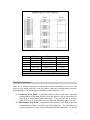
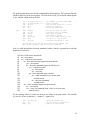
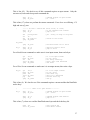
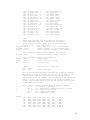
Figure 15.1 – DataFlash Memory Array Architecture
Sector
0
1
2
3
4
5
Block(s)
Pages
Bytes
0
0–7
2,112
1 – 31
8 – 255
65,472
32 – 63
256 – 511
67,584
64 – 127
512 – 1023
135,168
128 – 191
1024 – 1535
135,168
192 – 255
1536 – 2047
135,168
Each page is 264 bytes long
Each block is 8 pages long (2,112 bytes)
Figure 15.2 – Allocation of the DataFlash Memory
DataFlash Commands
There are 21 different operations we can perform with the DataFlash. For now we will
gloss over the details and look at the big picture, using the command names from the
Atmel datasheet. The pound sign (#) designates a buffer number, 1 or 2.
A) Continuous Array Read – a sequential stream of data is read from a specified
starting address in the main memory. Once the address is set up, any number of
bytes may be read without further addressing. If we reach the end of memory
(page 2047, byte 263), the address wraps back to the beginning (page 0, byte 0).
B) Main Memory Page Read – a sequential stream of data is read from a specified
starting address within a specified page of main memory. Once the address is
set up, any number of bytes may be read without further addressing. At the end
2