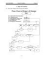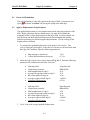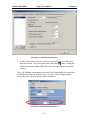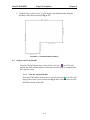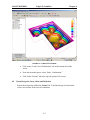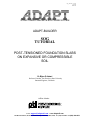
1
Sog_tutorial_cover10
041505
MNL422
STRUCTURAL CONCRETE SOFTWARE SYSTEM
ADAPT-BUILDER
SOG
TUTORIAL
POST-TENSIONED FOUNDATION SLABS
ON EXPANSIVE OR COMPRESSIBLE
SOIL
Dr Bijan O Aalami
Professor Emeritus, San Francisco State University
Structural Engineer, California
Affiliate Member
E-Mail [email protected]
www.adaptsoft.com
1733 Woodside Road, Suite 220, Redwood City, California, 94061, USA, Tel: (650) 306-2400 Fax (650) 364-4678
ADAPT - SOG
TUTORIAL
Sog_tutorial_toc10
070103
MNL422
LIST OF CONTENTS
1 - OVERVIEW.............................................................................................................. 1-1
2 – SOG MODEL GENERATION ............................................................................... 2-1
2.1
CREATE AND EDIT STRUCTURAL MODEL................................................................................2-1
2.1.1 Geometry.........................................................................................................................................2-1
2.1.2 Generate the Slab Region.............................................................................................................2-2
2.1.3 Generate the Stiffening Beams ....................................................................................................2-4
2.2
GENERATE BEAM AND SLAB TENDONS....................................................................................2-8
2.2.1 Beam Tendons................................................................................................................................2-9
2.2.2 Slab Tendons................................................................................................................................2-12
2.3
GENERATE BEAM AND SLAB TENDONS..................................................................................2-12
2.3.1 Concrete Material Properties .....................................................................................................2-12
2.4
APPLY LOADING.................................................................................................................................2-13
2.4.1 Uniform Live Load......................................................................................................................2-13
2.4.2 Perimeter Load.............................................................................................................................2-14
2.4.3 Load Combination.......................................................................................................................2-14
2.5
GENERATE MESH ...............................................................................................................................2-15
2.6
SAVE MODEL AS A TEMPLATE FOR BOTH SOIL CONDITIONS......................................2-16
3 – CENTER LIFT CONDITION ................................................................................ 3-1
3.1
FLOW CHART OF DESIGN OF SOG FOR CENTER LIFT CONDITION................................3-1
3.2
CREATE SOIL FOUNDATION............................................................................................................3-2
3.3
ANALYZE AND VERIFY RESULTS.................................................................................................3-3
3.4
CHECK DESIGN FOR STRESS, SHEAR AND DEFLECTION...................................................3-4
4 – EDGE LIFT CONDITION ...................................................................................... 4-1
4.1
FLOW CHART OF DESIGN OF SOG FOR EDGE LIFT CONDITION......................................4-1
4.2
CREATE SOIL FOUNDATION............................................................................................................4-2
4.3
APPLY A DISPLACEMENT ALONG PERIMETER ......................................................................4-2
4.4
ANALYZE AND VERIFY RESULTS.................................................................................................4-4
4.5
CHECK DESIGN FOR STRESS, SHEAR AND DEFLECTION...................................................4-5
i
ADAPT - SOG
TUTORIAL
Sog_tutorial_toc10
070103
MNL422
ii
ADAPT-BUILDER
OVERVIEW
Chapter 1
1 OVERVIEW
The following tutorial illustrates how to create, analyze and design the example in
Appendix A.7 of reference [PTI, 1996]. The tutorial is organized as follows:
•
•
•
Model Generation
o Geometry
o Material
o Post-tensioning
o Loading
o Mesh Generation
Center Lift Condition
o Soil Foundation
o Analysis
o Validation of Solution
o Design
Edge Lift Condition
o Soil Foundation
o Applied Displacement
o Analysis
o Validation of Solution
o Design
For a more comprehensive explanation of the solution for each swell mode, refer to
SOG User Manual.
1-1
ADAPT-BUILDER
SOG Model Generation
Chapter 2
2 SOG Model Generation
2.1
Create and Edit Structural Model
2.1.1
Geometry
The PTI Example A.7 consists of a Slab Region with a 4-inch thickness.
Stiffening Beams of dimensions 12”x 24” are placed in both directions with
the spacing shown in Figs.2.1-1(a) and (b).
(a) Slab and Beam Dimensions
(b) Beam Spacing
FIGURE 2.1-1 FOUNDATION GEOMETRY
2-1
ADAPT-BUILDER
2.1.2
SOG Model Generation
Chapter 2
Generate the Slab Region
To manually create the Slab Region, a three-foot grid can be used as a guide
to snap to. To setup a grid, use the following procedure.
1. From the Snap toolbar, click on the Grid Settings button. The Grid
Settings dialog box will appear as shown below.
Figure 2.1.2-1 Grid Settings Dialog Box
2. Change the X-spacing and Y-spacing to 3 ft, check mark the “Display
grid when active” setting and click OK.
3. From the Snap toolbar, click on the Snap to Grid button. A 3’x 3’
grid will appear.
4. In the View menu, click on the Display WCS . When manually
creating a model, you will want to make the project origin and the WCS
(World Coordinate System) coincide.
5. From the Camera and Viewports toolbar, click on the Top View
button.
6. From the Build menu, select Display Modeling toolbar, click on the
Create Slab Region button. Although two of the Slab vertices (16,0
ft and 16,12 ft) do not snap directly to the preset grid, you can snap
these two vertices to near the intended location (18,0 ft and 18,12 ft)
during the Slab creation mode. After the Slab has been created, the Xcoordinate can be manually input (16 ft) in the Slab Properties dialog
box.
7. The Slab Region is generated by snapping to the coordinates shown in
the following figure. Press “C” key to close the Slab Region.
2-2
ADAPT-BUILDER
SOG Model Generation
Chapter 2
(42,36)
(0,36)
(42,12)
(18,12)
(0,0)
(18,0)
Figure 2.1.2-2 Grid Coordinates For Snapping
Double click on the Slab Region to open its properties box or select the Slab
Region and open the properties box by clicking on the Item’s Properties
button.
8. Change the following parameters (Fig. 2.1.2-3), then click on the
button to accept the changes:
•
•
Thickness
Coordinates
#
2
3
4 inch
X
16
16
2-3
ADAPT-BUILDER
SOG Model Generation
Chapter 2
Figure 2.1.2-3 Modifications to Slab Region
2.1.3
Generate the Stiffening Beams
Stiffening Beams of dimensions 12”x20” will be used and offset 4” below
the Slab soffit, giving a total height of 24”.
1. From the Build toolbar, click on the Create Beam
tool. Next click on
the Item’s Properties button. Change the following parameters (Fig.
2.1.3-1), then click on the
button to accept the changes:
•
•
Cross-section
Width:
Depth:
Vertical Offset
12 in
20 in
4 in
Note: By changing the parameters before the Beam is created, the
modifications become the default values. Therefore, all Beams created
hereafter will have these specified dimensions and offset.
2-4
ADAPT-BUILDER
SOG Model Generation
Chapter 2
Figure 2.1.3-1 Modifications to Slab Region
2. Set Modeler’s object snapping properties so that Snap to Intersection
button is active (the icon will be highlighted after clicking the mouse).
Turn off all other snapping tools.
3. Create the perimeter Beams by snapping to the Slab edge as shown in
Fig. 2.1.3-2. Only create the Beams shown; the rest of the Beams will
be generated using the All Transformations tool in the Copy/Move
Toolbar.
2-5
ADAPT-BUILDER
SOG Model Generation
Chapter 2
Figure 2.1.3-1 Create Perimeter Beams by Snapping to Edge of Slab
4. To copy a Beam, select a Beam of similar length and click the All
Transformations tool. The Copy-Move dialog box will appear. Enter
the appropriate X and Y offset and press copy. Repeat this step for the
remaining Beams.
Figure 2.1.3-2 Copy-Move Dialog Box
5. To align the Beams flush with the Slab edge, click on the Align
tool located in the Modeling toolbar. Select
Structural Components
2-6
ADAPT-BUILDER
SOG Model Generation
Chapter 2
the Beam to be aligned by clicking on it. The following dialog box will
appear (Fig. 2.1.3-3).
Figure 2.1.3-3 LineUp Dialog Box
Choose the side that you believe is the correct shifting direction
according to the direction that the Beam was created and click OK.
The program will shift the Beam in that direction and then ask you if
the direction is correct. If you click yes, the Beam is placed at the
shown location. If you click no, the program automatically shifts
the Beam to the opposite side as shown below.
Proposed shifting
direction
Final Position
Figure 2.1.3-4 Beam Shift
6. Align the remaining Beams, according to the previous step.
2-7
ADAPT-BUILDER
2.2
SOG Model Generation
Chapter 2
Generate Beam and Slab Tendons
The Slab is reinforced with unbonded single strand (monostrand) post-tensioning
Tendons. There are eight Tendons in the longitudinal direction and thirteen
Tendons in the transverse direction (Fig. 2.2-1 and 2.2-2). The Tendons are
straight (no profile) and are located at the mid-depth of Slab, 2 in. down from the
top of Slab. The beam Tendons are draped and are located 3.25 in. from the bottom
of the Beams; both the beam Tendons and the slab Tendons are eccentric with
respect to the centroid of the ribbed Slab. The average precompression is 114 psi.
The profile of beam Tendons is shown in Fig. 2.2-3.
FIGURE 2.2-1
2-8
ADAPT-BUILDER
SOG Model Generation
(a) Layout of Tendons in plan
FIGURE 2.2-2 TENDON LAYOUT
Chapter 2
(b) 3D-view of Tendon layout
FIGURE 2.2-3
2.2.1 Beam Tendons
1. The beam Tendon profile is generated by creating three spans. The first
and last spans are reversed curves 3ft from the Slab edge. The second
span is straight. To create snapping guides for the first and last span,
draw lines along the Slab edge and offset them inward (using the
Manual Transformation ) from the Slab edge by 3ft as shown in the
diagram below (Fig. 2.2.1-1).
2-9
ADAPT-BUILDER
SOG Model Generation
Chapter 2
Snapping guides
(lines offset 3ft from
Slab edge)
FIGURE 2.2.1-1 SNAPPING GUIDES FOR BEAM TENDONS
2. Set Modeler’s object snapping properties so that Snap to Endpoint is
active. Turn off all other snapping tools.
3. To create a beam Tendon, click on the Create Tendon tool.
4. Snap to the endpoint of the Beam as shown in Fig 2.2.1-2.
5. Next activate the Snap to Perpendicular tool and snap to the
guideline located 3ft to the right of the Beam endpoint, as well as the
guideline 3ft left of the Beam endpoint.
6. Reactivate the Snap to Endpoint tool and snap to the Beam endpoint.
Press the “C” key to terminate the Tendon.
2-10
ADAPT-BUILDER
1
SOG Model Generation
Chapter 2
Beam Endpoint
2
Line offset 3ft from
Slab edge
3
Line offset 3ft from
Slab edge
Beam Endpoint
4
FIGURE 2.2.1-2 SNAPPING SEQUENCE FOR BEAM TENDONS
7. To generate the Tendon profile shown in Fig. 2.2-3, open the Tendon
properties box by either double clicking on the Tendon or selecting the
Tendon and then clicking the Item’s Properties tool.
8. Select the Shape/System/Friction tab as shown in Fig. 2.2.1-3. Enter the
button to
following parameters for each span, then click on the
accept the changes:
Span #
X1, X2, X3
Shape
Span1
0.49,0.50,0.49
Span2
0.10,0.50,0.10
Span3
0.49,0.50,0.49
Reversed 2, 11.37, 20.75
Parabola
Reversed 20.75, 3.25, 20.75
Parabola
Reversed 20.75, 11.37, 2
Parabola
2-11
CGS
Friction and System
Unbonded
Unbonded
Unbonded
ADAPT-BUILDER
SOG Model Generation
Chapter 2
FIGURE 2.2.1-3 SNAPPING SEQUENCE FOR BEAM TENDONS
2.2.2
Slab Tendons
Slab Tendons are single span Tendons that have a CGS of 2” from top and
bottom.
1. To quickly generate the slab Tendons, a master Tendon is created first
with the correct profile.
2. Now Tendons can replicated from the master using the All
Transformation tool as demonstrated in Section 2.1.3 for Beam
generation.
2.3
Set Material Properties for Concrete and Prestressing
2.3.1
Concrete Material Properties
1. To set the material properties for concrete, go to the Material menu and
select Concrete. The following dialog box will appear.
2-12
ADAPT-BUILDER
SOG Model Generation
Chapter 2
FIGURE 2.3.1-1 CONCRETE MATERIAL DIALOG BOX
2. Change the following parameters, then click OK.
• f’c:
2500 psi
• Ec:
1500 ksi
2.4
Apply Loading
2.4.1
Uniform Live Load
1. From the menu bar, click on Loading and select Display Loading
Toolbars from the pull down menu.
2. Click on the Slab. A change in color indicates that this Slab was
selected by the program.
3. Select Patch Load Wizard .
4. The dialog box shown in Fig. 2.4.1-1 opens. Change the “Load case” to
live load and the value to 0.04ksf. Note that the selfweight of the
structure is calculated automatically by the program, using the geometry
of the structural model and the unit weight defined by the user. The
program has the conventional unit weight value of concrete as its default
value.
2-13
ADAPT-BUILDER
SOG Model Generation
Chapter 2
FIGURE 2.4.1-1 PATCH LOAD WIZARD DIALOG BOX
2.4.2
Perimeter Load
1. To apply the perimeter loading, click on the Slab. A change in
color indicates that this Slab was selected by the program.
2. Select the Line Load Wizard tool.
3. The dialog box shown in Fig. 2.4.2-1 opens. Change the value to
1.04 k/ft and click on Create.
FIGURE 2.4.2-1 LINE LOAD WIZARD DIALOG BOX
2.4.3
Load Combination
1. From the menu bar, click on Loading and select Load
Combination from the pull down menu. The Combinations
dialog box appears.
2. By default the program automatically creates a load combination
called Basic Case, which includes Selfweight. To add the dead
load case to the combination, choose Dead load from the Load
cases combo box. Leave the Load factor value as 1. Click Add
under the Combination parts. Dead load will appear as part of
the combination. Repeat this step for live load and prestressing
(Fig. 2.4.3-1).
3. After all the load cases have been added in the Combination list,
click Save, then OK to close the dialog box.
2-14
ADAPT-BUILDER
SOG Model Generation
Chapter 2
FIGURE 2.4.3-1 LINE LOAD WIZARD DIALOG BOX
2.5
Generate Mesh
From the menu bar, select FEM and click on Display FEM Toolbars, a pull down
menu item. From the toolbars displayed, click on the button for Automatic Mesh
to open the dialog box shown in Fig. 2.5-1, and accept the default
Generation
values. After the completion of meshing, a message box shown in Fig. 2.5-2 will
open. Click Yes to view the meshing. This will show the automatic mesh generated
by the program, Fig. 2.5-3.
2-15
ADAPT-BUILDER
SOG Model Generation
Chapter 2
FIGURE 2.5-1 AUTOMATIC MESH GENERATION
FIGURE 2.5-2 MESHING VIEW MESSAGE BOX
FIGURE 2.5-3 PLAN VIEW OF THE SLAB MESHING
2.6
Save Model as a Template for Both Soil Conditions
This general model will be used as a template for both center lift and edge lift
condition. The model should be saved two times as:
•
PTI_Example_Center_Lift_EX7.adm
2-16
ADAPT-BUILDER
•
SOG Model Generation
PTI_Example_Edge_Lift_EX7.adm.
Note: The program does not allow spaces in file names.
2-17
Chapter 2
ADAPT-BUILDER
Center Lift Condition
Chapter 3
3 Center Lift Condition
3.1
Flow Chart of Design of SOG for Center Lift Condition
Flow Chart of Center Lift Design
Start
fb = representative bending stress
Fb = allowable stress
fv = representative shear stress
Fv = allowable shear stress
d = max deflection
fa = average precompression
a = em
Analyze Foundation
d <or = ym/3
Reduce a by 20%
d=?
Yes
d > ym/3
fb = ?
No
fb > Fb
fb < or = Fb
Modify Geometry
and/or PT
fv = ?
fv < or = Fv
fa = ?
Improve
analysis/design?
fv > Fv
fa > 75
Reduce PT for more
economical design?
Yes
No
50 < or = fa < 75
Exit
3-1
ADAPT-BUILDER
3.2
Center Lift Condition
Chapter 3
Create Soil Foundation
The soil foundation for the first iteration of center lift condition is placed at a
distance equal to em from edge of Slab.
1. To generate the soil foundation, click the Area Spring tool. Using the Snap
to Intersection tool, snap the Area Spring to the Slab vertices and press the
“C” key to close the spring.
2. Double click on the Area Spring to open its properties box or select the Area
Spring and open the properties box by clicking on the Item’s Properties
button (Fig. 3.2-1). Change the following parameters, then click on the
button to accept the changes:
•
•
kza (Bulk modulus of soil)
Coordinates
#
X
1
4.5
2
4.5
3
37.5
4
37.5
5
11.5
6
11.5
3-2
71 pci
Y
4.5
31.5
31.5
16.5
16.5
4.5
ADAPT-BUILDER
Center Lift Condition
Chapter 3
FIGURE 3.2-1 SOIL SUPPORT PROPERTIES BOX
3.3
Analyze and Verify Results
3.3.1
Convert Mesh into Elements and then Solve the Structure
From the pull down menu of FEM, select Analyze Structure
icon. This
will perform the finite element analysis of the structure and report its
completion on the computer screen.
3.3.2
View the Analysis Results
From the FEM toolbar, click on the View Analysis Result icon. This will
bring up the viewer screen, as shown in Fig. 3.3.2-1. Next, we will view the
deflection contour of the Slab.
•
Click on the “Load Cases/Combinations” tab on the bottom left of the
screen.
•
From the menu that opens, select “Basic Case”.
•
Click on the “Results” tab in the top left region of the screen.
3-3
ADAPT-BUILDER
•
Center Lift Condition
Chapter 3
Check that d < ym/3. Use the flow chart in Section 3.1 to help facilitate
any modifications if d > ym/3.
FIGURE 3.3.2-1 RESULTS VIEWER
3.4
Check Design for Stress, Shear and Deflection
Before checking the design stresses, shear and deflection, the analysis should be
validated as laid out in the flowchart of Section 3.1. When a valid solution is
obtained, the Slab is broken into design strips and design sections. The program
then performs a stress check on each design section. Shears and deflection for each
design section are also calculated. The following steps show you how to obtain the
results of the design.
1. In order to obtain design strips, you must first create Support Lines and design
strips in two orthogonal directions. Section 1.2 of the Modeler Tutorial can be
used as a guide in Support Line and design strip generation.
2. Click on the Generate Design Sections Automatically
tool from the FEM
pull down menu.
3-4
ADAPT-BUILDER
Center Lift Condition
Chapter 3
3. Design sections will be created automatically. Fig. 3.4-1 shows an example of
the Support Lines and the associated design strips for both X- and Y-direction.
If the image does not appear, click on Display Design Sections
button.
FIGURE 3.4-1 SUPPORT LINES AND DESIGN SECTIONS IN X-AND Y-DIRECTION
4. Click on the Design the Design Section(s)
button to execute a stress check for each
of the design sections shown, as well as to calculate the shears and deformations.
Figure 3.4-2(b) shows all the design strips of the X-direction in green, indicating that
the stresses do not exceed allowable values.
(b) Design section stress check results
(a) Design strip designation in X-direction
FIGURE 3. 4-2 DESIGN STRIPS AND STRESS CHECK RESULTS IN THE X-DIRECTION FOR
CENTER LIFT CONDITION
3-5
ADAPT-BUILDER
Center Lift Condition
Chapter 3
5. The actions of each Support Line are shown separately. To see the design actions of a
Support Line:
•
Click on one of the design sections of the design strip. A change in color of
the Support Line indicates that this design strip was selected. Go to the
results summary screen by clicking on the Show Design Summary
option from the FEM pull down menu. The result summary window will
open.
•
From the combo box at the top of the screen select Basic Case. Then click
on the Stress Diagram button on the left of it. A distribution, such as shown
in Fig. 3.4-3, appears. This distribution shows the magnitude of the stress
for the Support Line selected.
•
A similar graph for shear can be generated by clicking on the Shear
Diagram button.
FIGURE 3.4-3 DISTRIBUTION OF DESIGN STRESS IN “RESULTS SUMMARY”
3-6
ADAPT-BUILDER
Edge Lift Condition
Chapter 4
4 Edge Lift Condition
4.1
Flow Chart of Design of SOG for Edge Lift Condition
Flow Chart of Edge Lift Design
Start
fb = representative bending stress
Fb = allowable stress
fv = representative shear stress
Fv = allowable shear stress
d = max deflection
fa = average precompression
Calculate
using PTI formula
Analyze Foundation
<d
a=?
d=?
> or = d
Reduce a by 20%
a > 3em
a < or = 3em
fb = ?
fb > Fb
Modify Geometry
and/or PT
fb < or = Fb
fv = ?
fv > Fv
fv < or = Fv
fa = ?
Yes
Reduce PT for more
economical design?
fa > 75
No
50 < or = fa < 75
Exit
4-1
ADAPT-BUILDER
4.2
Edge Lift Condition
Chapter 4
Create Soil Foundation
The soil foundation for edge lift is placed at the edge of Slab. Generate an Area
Spring as shown in Section 3.2, leaving the spring at the Slab edge.
4.3
Apply a Displacement Along Perimeter
The applied displacement is a line displacement placed along the perimeter of the
Slab. Before generating the line displacement, you must first calculate the
magnitude of the average displacement for the entire Slab. For this example, the
long direction and short direction Beams have different lengths and spacing;
therefore producing two different applied displacements. Use the average of the
displacements calculated.
1. To calculate the applied displacement, click on the Criteria menu. The
Criteria dialog box will appear. Select the Soil Parameters tab and check mark
the Edge Lift Condition. Input the following parameters:
•
•
Edge moisture variation em:
Vertical differential movement ym:
5.5 ft
0.71 in
2. Select the Edge Displacements tab as shown in Fig. 4.3-1. Enter the following
parameters for each direction and click Calculate.
•
•
•
•
•
•
•
Slab edge label:
Construction geometry:
Slab length normal to edge L:
Average rib spacing normal to edge S:
Rib’s total depth (average h):
Average weight on Slab edge P:
Calculated Displacement
Long direction
Ribbed Slab
42 ft
12 ft
24 in
1.04 k/ft
0.35 in
•
•
•
•
•
•
•
Slab edge label:
Construction geometry:
Slab length normal to edge L:
Average rib spacing normal to edge S:
Rib’s total depth (average h):
Average weight on Slab edge P:
Calculated Displacement
Short direction
Ribbed Slab
24 ft
14 ft
24 in
1.04 k/ft
0.33 in
3. Use 0.34 in as the average applied displacement.
4-2
ADAPT-BUILDER
Edge Lift Condition
Chapter 4
FIGURE 4.3-1 CRITERIA DIALOG BOX
4. In the Loading menu, select Line Displacement for the Apply Displacement
drop down menu. Next click on the Item’s Properties button. Change the
following parameters (Fig. 4.3-2), then click on the
button to accept the
changes:
Note: By changing the parameters before the Line Displacement is created, these
modifications become the default values. Therefore, all Line Displacements
created hereafter will have this specified Z translation.
FIGURE 4.3-2 CRITERIA DIALOG BOX
4-3
ADAPT-BUILDER
Edge Lift Condition
Chapter 4
5. Using the Snap to Intersection tool, snap the line displacements along the
perimeter of the Slab as shown in Fig. 4.3-3.
FIGURE 4.3-3 APPLIED DISPLACEMENT
4.4
Analyze and Verify Results
From the FEM pull down menu, select Analyze Structure
icon. This will
perform the finite element analysis of the structure and report its completion on
the computer screen.
4.4.1
View the Analysis Results
From the FEM toolbar, click on the View Analysis Results icon. This will
bring up the viewer screen, as shown in Fig. 4.4.1-1. Next, we will view the
deflection contour of the Slab.
4-4
ADAPT-BUILDER
Edge Lift Condition
Chapter 4
FIGURE 4.4.1-1 RESULTS VIEWER
4.5
•
Click on the “Load Cases/Combinations” tab on the bottom left of the
screen
•
From the menu that opens, select “Basic_Combination.”
•
Click on the “Results” tab in the top left region of the screen.
Check Design for Stress, Shear and Deflection
Repeat the design step outlined in Section 3.4. Your final design is based on the
worst-case scenario of the two soil conditions.
4-5