1
ADAPT-BUILDER
Center Lift Condition
Chapter 3
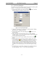
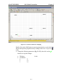
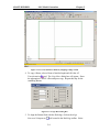
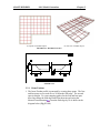
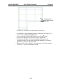
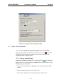
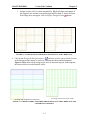
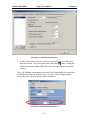
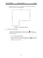
3. Design sections will be created automatically. Fig. 3.4-1 shows an example of
the Support Lines and the associated design strips for both X- and Y-direction.
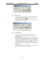
If the image does not appear, click on Display Design Sections
button.
FIGURE 3.4-1 SUPPORT LINES AND DESIGN SECTIONS IN X-AND Y-DIRECTION
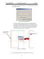
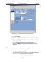
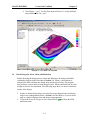
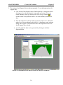
4. Click on the Design the Design Section(s)
button to execute a stress check for each
of the design sections shown, as well as to calculate the shears and deformations.
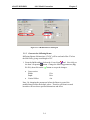
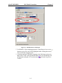
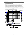
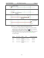
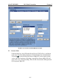
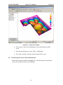
Figure 3.4-2(b) shows all the design strips of the X-direction in green, indicating that
the stresses do not exceed allowable values.
(b) Design section stress check results
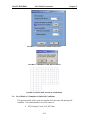
(a) Design strip designation in X-direction
FIGURE 3. 4-2 DESIGN STRIPS AND STRESS CHECK RESULTS IN THE X-DIRECTION FOR
CENTER LIFT CONDITION
3-5