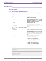
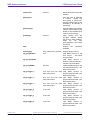
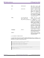
1
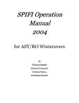
LPCScrypt User Guide
Rev. 1.5.2 — 23 June, 2015
User Guide
NXP Semiconductors
LPCScrypt User Guide
23 June, 2015
Copyright © 2014-2015 NXP Semiconductors
All rights reserved.
LPCScrypt User Guide -
User Guide
All information provided in this document is subject to legal disclaimers
Rev. 1.5.2 — 23 June, 2015
© 2014-2015 NXP Semiconductors. All rights reserved.
ii
NXP Semiconductors
LPCScrypt User Guide
1. Revision History .................................................................................................. 1
1.1. v1.5.2 ....................................................................................................... 1
1.2. v1.5 ......................................................................................................... 1
1.3. v1.3 ......................................................................................................... 1
1.4. v1.2 ......................................................................................................... 1
2. Introduction ......................................................................................................... 2
2.1. LPCScrypt overview .................................................................................. 2
2.2. Installation contents .................................................................................. 2
2.3. Creating binary files .................................................................................. 3
2.3.1. Image (vector) checksum ................................................................ 3
3. Host and Target Setup ........................................................................................ 4
3.1. Target configuration .................................................................................. 4
3.1.1. Keil MCB1857/4357 configuration .................................................... 4
3.1.2. LPC-Link2 configuration .................................................................. 4
3.2. Linux install notes ..................................................................................... 5
3.2.1. Ubuntu (13.04 and earlier) .............................................................. 5
3.2.2. Ubuntu (13.10 and later) ................................................................. 5
3.2.3. Fedora ........................................................................................... 5
3.3. Installing host drivers ................................................................................ 5
3.3.1. Windows: Installing DFU and VCOM drivers .................................... 5
3.3.2. Linux: Installing udev rules ............................................................. 6
3.3.3. Mac OS X ..................................................................................... 6
3.4. Booting LPCScrypt firmware ...................................................................... 6
3.5. LPCScrypt serial ports .............................................................................. 6
4. Simple Tutorial .................................................................................................... 7
4.1. Basic LPCScrypt usage ............................................................................. 7
4.1.1. Booting LPCScrypt ......................................................................... 7
4.1.2. Obtaining information about the target MCU ..................................... 7
4.1.3. Programming internal flash ............................................................. 9
4.1.4. Using a script ............................................................................... 10
4.1.5. Programming internal flash bank B ................................................ 10
4.1.6. Programming SPIFI ...................................................................... 10
4.1.7. Erasing SPIFI ............................................................................... 10
4.2. Image_manager utility and secure booting ................................................ 11
4.2.1. Creating an image to run from RAM .............................................. 12
4.2.2. Programming an AES encrypted image to SPIFI flash for secure
boot ...................................................................................................... 12
4.2.3. Basic scripting .............................................................................. 13
4.2.4. Advanced scripting ....................................................................... 13
4.2.5. Testing secure boot images .......................................................... 13
5. Reference ......................................................................................................... 14
5.1. LPCScrypt .............................................................................................. 14
5.1.1. The LPCScrypt command-line tool ................................................ 14
5.1.2. LPCScrypt commands .................................................................. 15
5.2. Image manager ...................................................................................... 19
5.2.1. Image manager command-line tool options .................................... 19
5.3. LPCScrypt example images ..................................................................... 19
6. Appendix A: LPCScrypt serial ports in depth ....................................................... 21
6.1. Multiple serial ports ................................................................................. 21
6.2. Host OS serial ports ............................................................................... 21
6.2.1. Windows ...................................................................................... 21
6.2.2. Linux ........................................................................................... 21
6.2.3. Mac OS X ................................................................................... 22
7. Legal Information ............................................................................................... 23
7.1. Definitions ............................................................................................... 23
7.2. Disclaimers ............................................................................................. 23
7.3. Trademarks ............................................................................................ 24
LPCScrypt User Guide -
User Guide
All information provided in this document is subject to legal disclaimers
Rev. 1.5.2 — 23 June, 2015
© 2014-2015 NXP Semiconductors. All rights reserved.
iii
NXP Semiconductors
LPCScrypt User Guide
1. Revision History
1.1 v1.5.2
• Windows only: added Start menu shortcuts for scripts to boot LPCScrypt and to program
debug probe firmware.
• Windows only: added CMSIS-DAP drivers to drivers directory.
• Improved scripts to program debug probe firmware.
• Various minor bug fixes, including:
• host app now correctly handles [memory_name + offset] calculation
• SPIFI size corrected for W25Q128FV
1.2 v1.5
• Added binaries for CMSIS-DAP and Segger J-Link debug probe firmware.
• Added scripts to enable easy programming of CMSIS-DAP and J-Link firmware.
• Added LPC-Link2 Debug Probe Firmware Programming guide.
• Added support for new SPIFI devices – W25Q128FV and MX25L1606.
• Improved reporting of partID information.
1.3 v1.3
• Added support for connections via USB1 as well as USB0.
• Added support for new SPIFI devices – W25Q40CV and PM25LQ032C.
• Fixed issue with download of binaries which are not a multiple of 4 bytes in size.
• Improved error handling when host could not gain control of target device.
• Updated documentation to reflect maximum image size for secure boot.
1.4 v1.2
• First public release.
LPCScrypt User Guide -
User Guide
All information provided in this document is subject to legal disclaimers
Rev. 1.5.2 — 23 June, 2015
© 2014-2015 NXP Semiconductors. All rights reserved.
1
NXP Semiconductors
LPCScrypt User Guide
2. Introduction
2.1 LPCScrypt overview
LPCScrypt is a fast flash and security programming tool for the LPC18/43 family of
microcontrollers. Key features include:
• Multi-Platform Support (Windows, Mac, Linux)
• Scriptable interface
• Programming of internal and SPIFI flash
• Support for a wide range of SPIFI devices
• Optimised for high speed operation – typically 100-200KB/sec, depending upon flash
device, host OS and host computer.
• Programming EEPROM (internal flash parts only)
• Programming One-Time Programmable (OTP) memory
• Generating and programming 128 bit AES keys (S parts only)
• Encrypting and programming secure images (S parts only)
Important Note
Due to export control regulations, support for creating AES keys and secure
images is not included in some versions of LPCScrypt. Please contact your
supplier for details on obtaining a version of LPCScrypt that supports these
features.
LPCScrypt consists of two parts, a multi-platform command line tool and an MCU firmware
monitor. In use, the firmware monitor is downloaded to the target MCU using USB DFU
support built into the on-chip ROM (using the target MCU USB0 or USB1 port). The firmware
creates a virtual serial port (VCOM) over USB to communicate with the host.
The LPCScrypt host tool provides a command-line interface to the firmware, giving access
to the programmable features of the MCU. It can be invoked with a single command or a
script file containing a sequence of commands.
Standard host tools, such as Windows batch files or Linux/Mac shell scripts, can be used
with the LPCScrypt host tool to automate multiple operations, such as binary file encryption,
programming binary files to flash devices, setting boot options, configuring VID/PID, and
finally simulating MCU reset.
LPCScrypt is flexible and fast, and is suitable for one off programming and testing or semiautomated production programming.
2.2 Installation contents
An LPCScrypt installation contains these directories:
• bin — containing the host and target executables
• docs — containing LPCScrypt documentation
• images — a set of pre-built binaries for testing and experimenting with LPCScrypt
features on Keil MCB1857/4357 or LPC-Link2 boards
LPCScrypt User Guide -
User Guide
All information provided in this document is subject to legal disclaimers
Rev. 1.5.2 — 23 June, 2015
© 2014-2015 NXP Semiconductors. All rights reserved.
2
NXP Semiconductors
LPCScrypt User Guide
• scripts — script for booting LPCScrypt firmware, programming debug probes and
various example scripts described later in this document
• probe_firmware — contains debug probe firmware images for programming LPC-Link2
and LPCXpressoV2/V3 debug probes. For more information, please see the ‘LPC-Link2
Debug Probe Firmware Programming’ manual.
• Drivers (Windows only) — Windows drivers for the booted and unbooted LPCScrypt
target.
2.3 Creating binary files
LPCScrypt can be used to download either plain binary files or binary files wrapped with a
header (as described later). This means that you will need to configure your development
tools to generate plain binary files.
If you are using the LPCXpresso IDE, then to create a binary file suitable for downloading
via LPCScrypt you will need to enable post-build steps for your project. For more details,
please see:
http://www.lpcware.com/content/faq/lpcxpresso/generating-srec-binaryand-ihex-files
For creating binary files with other toolchains, please check their documentation.
2.3.1 Image (vector) checksum
When booting from internal flash. the LPC18/LPC43 ROM bootloader uses a simple
checksum of the flash image to check for a valid boot image. This (vector) checksum is
stored in the 8th vector (offset 0x1c) and is calculated as the 1’s complement of the sum
of the first 7 32-bit values (vectors) in the image. If the checksum is not valid, the ROM
bootloader will not start the image. This checksum only applies when booting from internal
flash and is not applicable to external (i.e. SPIFI) flash.
By default, the LPCScrypt program command does not calculate the checksum, and
programs the binary image directly into the target memory, unchanged. An option is
provided to allow the checksum to be generated and programmed while flash programming
the device:
•
+c — Use this option to calculate the checksum and place it into the correct flash location.
This option is useful if your toolchain does not support the creation of the checksum, or
if the system used to build the binary image has not calculated the checksum.
Similarly, the LPCScrypt verify command does not calculate the checksum but performs
a word-for-word comparison of the binary image against the target memory. However, two
options are provided to give additional control over verifying the checksum:
•
+c — Use this option to calculate the checksum on the image to be verified before starting
the verify operation.
•
LPCScrypt User Guide -
User Guide
— Use this option to ignore the checksum word during the verify operation. This may
be useful when verifying an image in a flash bank whose checksum has been zeroed
by the IAP setboot function.
+i
All information provided in this document is subject to legal disclaimers
Rev. 1.5.2 — 23 June, 2015
© 2014-2015 NXP Semiconductors. All rights reserved.
3
NXP Semiconductors
LPCScrypt User Guide
3. Host and Target Setup
3.1 Target configuration
To use the LPCScrypt tool, the target MCU (i.e. the device to be programmed) must be
configured to boot from either its USB0 or USB1 port and reset. If your board has both USB
ports available, use of USB0 is prefered since this usually supports faster operation.
Note: This boot mode requires that a 12 MHz external crystal is connected to the XTAL1/2
pins. Please see the LPC18/43 user manual for more information.
LPC18/43 parts can be configured to boot from several different sources. The boot mode
is normally determined by the states of the boot pins P2_9, P2_8, P1_2, and P1_1. These
are typically brought onto a development board as DIP switches or jumpers.
Warning
The OTP memory can be programmed to override these boot pin settings. If
this is done, it may no longer be possible to boot the LPCScrypt firmware.
In the tutorial section of this manual we shall make use of the following boot sources:
• boot from USB0 – to DFU boot the LPCScrypt firmware
• boot from SPIFI flash – to run an image from SPIFI flash
• boot from internal flash – to run an image from internal flash.
Note
If a valid image is programmed into parts with internal flash, on reset the
LPC18/43 will boot this image unless the ISP input is held during reset. This
behavior overrides the settings of the OTP and boot pins.
The following subsections describe the target configuration of specific boards. For other
boards, please see their documention.
3.1.1 Keil MCB1857/4357 configuration
• To boot from USB0: boot jumpers P2_9 and P1_2 set to L, P2_8 and P1_1 set to H.
• To boot from SPIFI: boot jumpers P2_9, P1_2 and P2_8 set to L, P1_1 set to H.
Figure 3.1. MCB1857/4357 Boot Pins
3.1.2 LPC-Link2 configuration
LPC-Link2 can operate as both a debug probe and an development board for the LPC4370
MCU. For exploring the LPC4370 with LPCScrypt:
• To boot from USB0: JP1 not fitted.
LPCScrypt User Guide -
User Guide
All information provided in this document is subject to legal disclaimers
Rev. 1.5.2 — 23 June, 2015
© 2014-2015 NXP Semiconductors. All rights reserved.
4
NXP Semiconductors
LPCScrypt User Guide
• To boot from SPIFI: JP1 fitted.
Figure 3.2. LPC-Link2 JP1 Boot Pin
Note The MCU on the LPC-Link2 has no internal flash.
3.2 Linux install notes
The lpcscrypt installer and the tool itself are 32-bit applications and requires 32-bit libraries
to run.
To install the required 32-bit libraries on a 64-bit installation, run the command appropriate
to your system:
3.2.1 Ubuntu (13.04 and earlier)
sudo apt-get update
sudo apt-get install linux32 ia32-libs
3.2.2 Ubuntu (13.10 and later)
sudo apt-get update
sudo apt-get install libc6:i386 libusb-dev:i386 uuid-dev:i386 \
libgtk2.0-0:i386 gtk2-engines-murrine:i386
3.2.3 Fedora
sudo yum install glibc.i686 libgcc.i686 libstdc++.i686 libusb.i686 \
libuuid.i686 gtk2.i686
3.3 Installing host drivers
Depending on the chosen host, device drivers may be required as detailed below.
3.3.1 Windows: Installing DFU and VCOM drivers
If LPCXpresso v7 or later has been installed on your PC, all necessary drivers will have
been installed. However, to use LPCScrypt on a ‘clean’ machine, two device drivers need
to be installed:
• LpcDevice – the Windows device driver for an unbooted LPC18/43 MCU in DFU mode
• LPC-LinkII UCom – the Windows device for the LPCScrypt firmware USB serial port.
LPCScrypt User Guide -
User Guide
All information provided in this document is subject to legal disclaimers
Rev. 1.5.2 — 23 June, 2015
© 2014-2015 NXP Semiconductors. All rights reserved.
5
NXP Semiconductors
LPCScrypt User Guide
To install the drivers, a script called InstallDrivers is provided in the scripts directory. This
script must be run as an Administrator to enable the drivers to be installed.
3.3.2 Linux: Installing udev rules
Linux does not require a driver for VCOM. However, by default, the tty device (i.e. /dev/
ttyACM*) is not writable by regular users. To correct this a ‘udev rules’ file must be installed.
A udev rules file is provided in the scripts directory and can be installed by running the
following command:
sudo scripts/install_udev_rules
3.3.3 Mac OS X
Mac OS X does not require any special procedure for working with the USB serial port.
3.4 Booting LPCScrypt firmware
Before using the LPCScrypt host tool, the LPCScrypt firmware image must be downloaded
into the RAM of the target MCU. This is done by connecting the target’s configured boot
USB port to the host and using the boot_lpcscrypt script, located in the scripts directory
of the installation.
Note
Due to restrictions with the dfu-util utility used by boot_lpcscrypt, only one
unbooted MCU may be connected. However, they may be connected and
booted one at a time. After that, any number of MCUs with the LPCScrypt
firmware may be connected and programmed by the LPCScrypt host tool, each
of them communicating over a different USB serial (VCOM) port.
3.5 LPCScrypt serial ports
Once booted, the LPCScrypt firmware enumerates as a USB serial (VCOM) device on the
host. In most circumstances this will be detected automatically when LPCScrypt is launched
on the host.
If more than one MCU running LPCScrypt firmware is connected to a host, or other VCOM
connections exist, then you will be prompted to select the appropriate serial port, as below:
Multiple serial ports found:
COM5
COM7
Use -d serial_port to select
For more details regarding serial ports selection and potential problems, see Chapter 6.
LPCScrypt User Guide -
User Guide
All information provided in this document is subject to legal disclaimers
Rev. 1.5.2 — 23 June, 2015
© 2014-2015 NXP Semiconductors. All rights reserved.
6
NXP Semiconductors
LPCScrypt User Guide
4. Simple Tutorial
4.1 Basic LPCScrypt usage
In this tutorial we are going to use LPCScrypt to program some applications into the internal
flash and SPIFI flash of a Keil MCB1857 or MCB4357 board. Ensure this board is configured
to boot from USB0 and has been reset (this may require ISP to be held during reset/power
on). See Section 3.4 on booting LPCScrypt firmware for more details.
4.1.1 Booting LPCScrypt
Open a command prompt on your host machine, navigate to the scripts subdirectory and
execute the command to download the LPCScrypt firmware to the target MCU.
For Windows this is:
boot_lpcscrypt.cmd
Alternatively, this script may be called directly from the LPCScrypt entry in the Windows
Start menu.
On non-Windows hosts, use:
./boot_lpcscrypt
A message similar to this should now be displayed, confirming that the LPCScrypt firmware
has been downloaded:
Booting LPCScrypt target with "LPCScrypt_48.bin.hdr"
LPCScrypt target booted
4.1.2 Obtaining information about the target MCU
Now we use LPCScrypt to tell us something about the target MCU. Navigate to the bin
subdirectory and enter a command such as the following.
lpcscrypt querypart
This displays details of the part and how much internal flash it has:
partID = 0xa001c830 0x0
decode = LPC4357: BankA 512 KB, BankB 512 KB
Core Clock = 180000000
We can also get more information about the flash — both internal flash and any connected
SPIFI flash devices:
lpcscrypt queryflash
In this example we have details of two banks of internal flash, one block of EEPROM and
external SPIFI flash:
Number of Flash Devices = 4
LPCScrypt User Guide -
User Guide
All information provided in this document is subject to legal disclaimers
Rev. 1.5.2 — 23 June, 2015
© 2014-2015 NXP Semiconductors. All rights reserved.
7
NXP Semiconductors
LPCScrypt User Guide
Name = SPIFI
Base = 0x14000000
Size = 0x400000
Page = 0x100
Sector = 0x10000
Blank = 0xff
Buffer = 0x8000
Name = BankA
Base = 0x1a000000
Size = 0x80000
Page = 0x1000
Sector = 8-64KB
Blank = 0xff
Buffer = 0x8000
Name = BankB
Base = 0x1b000000
Size = 0x80000
Page = 0x1000
Sector = 8-64KB
Blank = 0xff
Buffer = 0x8000
Name = EEPROM
Base = 0x20040000
Size = 0x3f80
Page = 0x80
Sector = NA
Blank = 0x0
Buffer = 0x8000
We can also obtain more details on the SPIFI flash:
lpcscrypt queryspifi
which in this case is a 4MB Spansion part:
Device family = S25FL032P
Device size = 0x400000
Erase Sector size = 0x10000
Write page size = 0x100
SPIFI final rate = 60000000
Devices supported by firmware:
- PM25LQ032C
- MX25L1606E
- MX25L1635E
- MX25L3235E
- MX25L6435E
- MX25L8035E
- S25FL016K
- S25FL032P
- S25FL064P
- S25FL129P 64kSec
- S25FL129P 256kSec
- S25FL164K
LPCScrypt User Guide -
User Guide
All information provided in this document is subject to legal disclaimers
Rev. 1.5.2 — 23 June, 2015
© 2014-2015 NXP Semiconductors. All rights reserved.
8
NXP Semiconductors
LPCScrypt User Guide
- S25FL256S 64kSec
- S25FL256S 256kSec
-
S25FL512S
W25Q40CV
W25Q32FV
W25Q64FV
W25Q128FV
W25Q80BV
The output also lists the SPIFI devices supported by this version of LPCScrypt.
Support for SPIFI flash within LPCScrypt is provided by the LPCOpen SPIFI library.
Note
Certain SPIFI devices share common internal identifiers – for example a
W25Q16DV is a ‘clone’ of S25FL016K. As a result, some parts that are not
listed above may still work without issue.
4.1.3 Programming internal flash
Having obtained some information on the target MCU, we will now program an image into
the internal flash:
lpcscrypt program ..\images\MCB1800_blinky_BankA.bin BankA
Once programming is completed it will return a confirmation message, for example:
..
Programmed 5456 bytes to 0x1a000000 in 0.021s (258.923KB/sec)
Note
The flash address to program can either be specified as a numeric hex address
or (if programming from the base address of the flash) as the name returned
from a queryflash command. Images can be programmed at an offset from
the flash base address, but care must be taken to link and align such images
to a flash sector base address.
We can also run a verify operation to confirm that the image has programmed correctly:
lpcscrypt verify ..\images\MCB1800_blinky_BankA.bin BankA
which, once completed, will return a confirmation message like this:
.
Verified 5456 bytes to 0x1a000000 in 0.004s (1370.402KB/sec)
If you now reset the board, you should see the image you programmed running on the
target MCU.
Tip
Alternatively, you can run the image using the LPCScrypt command
gotoImage BankA.
LPCScrypt User Guide -
User Guide
All information provided in this document is subject to legal disclaimers
Rev. 1.5.2 — 23 June, 2015
© 2014-2015 NXP Semiconductors. All rights reserved.
9
NXP Semiconductors
LPCScrypt User Guide
4.1.4 Using a script
Rather than passing single commands to LPCScrypt, you can use the -s argument to pass
a file of commands. Thus we could combine the above sequence to program and verify
into a single script file called (for example) ‘bankAprog.txt’ and containing:
program
verify
..\images\MCB1800_blinky_BankA.bin BankA
..\images\MCB1800_blinky_BankA.bin BankA
We could then execute this script using:
lpcscrypt -s bankAprog.txt
4.1.5 Programming internal flash bank B
The commands for programming and running an image from bank B are similar to those
for bank A. However, an additional command is required to force booting from bank B,
because bank A is the default.
program ..\images\MCB1800_blinky_BankB.bin BankB
verify
..\images\MCB1800_blinky_BankB.bin BankB
setboot BankB
The following command can then be used to switch back to booting the bank A image.
lpcscrypt setboot BankA
4.1.6 Programming SPIFI
Firstly, for a part with internal flash, you may need to erase the internal flash in order for
code in SPIFI to boot from reset. To do this use:
lpcscrypt erase BankA
lpcscrypt erase BankB
Then program the image into SPIFI flash using:
lpcscrypt program
lpcscrypt verify
..\images\MCB1800_blinky_SPIFI.bin SPIFI
..\images\MCB1800_blinky_SPIFI.bin SPIFI
Remember that you will need to change the boot jumpers in order to boot from SPIFIflash
at reset.
4.1.7 Erasing SPIFI
SPIFI flash can be erased in the same way as internal flash.
lpcscrypt erase SPIFI
Warning
Erasing some SPIFI devices can take many seconds so it may appear that the
process has hung. This is not the case – be patient!
LPCScrypt User Guide -
User Guide
All information provided in this document is subject to legal disclaimers
Rev. 1.5.2 — 23 June, 2015
© 2014-2015 NXP Semiconductors. All rights reserved.
10
NXP Semiconductors
LPCScrypt User Guide
You can also erase a portion of a flash device, as below:
lpcscrypt erasesector SPIFI
This will erase one sector of the SPIFI flash starting from the SPIFI flash base address.
Note: The size of one sector of a flash device is reported by the queryflash command.
Multiple sequential sectors can also be erased using a single command:
lpcscrypt erasesector SPIFI 4
Tip
Some SPIFI flash support optimised whole device erase, so for programming
large images, faster overall performance may be seen by performing an erase
before a programming operation.
4.2 Image_manager utility and secure booting
Note
Support for encrypting images is not available in all versions of LPCScrypt.
Supplied as part of the LPCScrypt package is a utility called image_manager, which provides
two main functions. It can:
• add standard header information to a binary file required for either a DFU or a Secure
boot operation from SPIFI Flash (LPC18S/43S parts only)
• encrypt a binary file using a supplied AES key.
Full details on secure boot are given in the User Manual for the MCU. However, there are
some key points to note about secure booting from SPIFI flash.
• Any binary image designed for secure booting must be linked to run from RAM at
0x10000000 and be no larger than the size of the local SRAM block starting at
0x10000000. This is essential since the image will be decoded and copied into this SRAM
block before being executed.
Note
Check the User Manual for your MCU to determine the size of this SRAM block
The AES key used to encrypt the image must be programmed into the MCU OTP memory.
Important Warning
Programming an AESkey into the MCU is a one-time-only operation. The
programming of a key sets its value permanently in one-time-programmable
memory, and future debug connections are disabled.
Therefore under most circumstances this is the last operation to be performed before the
MCU enters service.
In operation, LPCScrypt is designed to be fully script driven. However, the examples in this
section explain some key points as separate operations.
LPCScrypt User Guide -
User Guide
All information provided in this document is subject to legal disclaimers
Rev. 1.5.2 — 23 June, 2015
© 2014-2015 NXP Semiconductors. All rights reserved.
11
NXP Semiconductors
LPCScrypt User Guide
4.2.1 Creating an image to run from RAM
Sometimes it can be useful to download an image (built to run at 0x10000000) into RAM
and execute it – for example, in order to test an image that you will later encrypt for secure
booting (which is covered in more detail in the next subsection).
To do this we first need to generate a version of the binary containing a header. Navigate
to the images subdirectory and enter:
..\bin\image_manager -i MCB1800_blinky_RAM.bin \
-o MCB1800_blinky_RAM.bin.hdr --bin
which will generate the required file with a header. The output should look like this:
image_manager v2.0.4 (Build 18) (Oct 7 2014 13:48:27)
Writing out file: MCB1800_blinky_RAM.bin.hdr, size - 4624 bytes
Now, to download to RAM, you can use the boot_lpcscrypt script. First reset your board
with the boot pins set to boot from USB0, and then enter:
..\scripts\boot_lpcscrypt MCB1800_blinky_RAM.bin.hdr
This will download your executable image (instead of the default LPCScrypt firmware) to
RAM, and then execute it.
4.2.2 Programming an AES encrypted image to SPIFI flash for secure
boot
Develop and test an application using your favourite toolchain – such as LPCXpresso.
Ensure it is linked and tested to run from RAM at 0x10000000 and is less than the size of
the local SRAM bank at 0x10000000. Extract a binary image from the generated .axf file.
• DFU boot the LPCScrypt firmware onto the MCU.
• Call LPCScrypt with a single command to generate a 128-bit key from the MCU random
generator.
• Call Image Manager to encrypt the binary image with the 128-bit key and add the required
header.
• Call LPCScrypt and pass a single command to flash the encrypted image.
• Call LPCScrypt and pass a single command to verify the flash operation.
• Call LPCScrypt and pass a single command to program the AES 128-bit key into OTP
memory on the MCU.
Important Warning
Once an AES key is programmed into the MCU, no further debug operations
will be possible with that device.
boot_lpcscrypt
lpcscrypt genkeytarget
--->>> 977e4c70dd602705570b82f2c4333989
image_manager -key 977e4c70dd602705570b82f2c4333989 \
--i <path to binary> -o <path to binary.hdr> --bin
LPCScrypt User Guide -
User Guide
All information provided in this document is subject to legal disclaimers
Rev. 1.5.2 — 23 June, 2015
© 2014-2015 NXP Semiconductors. All rights reserved.
12
NXP Semiconductors
LPCScrypt User Guide
lpcscrypt program <path to binary.hdr> SPIFI
lpcscrypt verify <path to binary.hdr> SPIFI
If there are no errors and you no longer need to perform debug operations on this device,
do:
lpcscrypt aesProgramKey1 977e4c70dd602705570b82f2c4333989
4.2.3 Basic scripting
As described in Section 4.1.4, you can use the -s argument to pass a file of commands
to LPCScrypt in one operation. The following example script combines three of the steps
described above:
# commands to flash, verify and program an AES key
program <path to binary.hdr> SPIFI
verify <path to binary.hdr> SPIFI
aesProgramKey1 977e4c70dd602705570b82f2c4333989
You would run it like this:
lpcscrypt -s <path to script file>
4.2.4 Advanced scripting
It is also possible to combine the scripting ability of LPCScrypt with the facilities provided
by the host system’s command line (shell scripts or batch files). The scripts subdirectory
of the LPCScrypt bundle contains example scripts.
For example, the ‘encrypt_and_program’ script creates a (random) AES key, encrypts a
binary image, programs it into SPIFI flash, and then sets the AESkey on the target MCU.
Its usage is:
encrypt_and_program <path to binary>
4.2.5 Testing secure boot images
Make sure the image works when DFU booted directly into RAM before you try to encrypt it.
When testing secure booting, you can encrypt a binary file with a ‘0’ key and test it on the
MCU without having programmed any AESkey into the MCU.
Warning
Do not program the MCU AESkey with 0. Doing this will have the same effect as
any other AESkey programming – no further debug operations will be possible
with this MCU. You can boot from a file that is encrypted with a ‘0’ key without
programming the AESkey.
LPCScrypt User Guide -
User Guide
All information provided in this document is subject to legal disclaimers
Rev. 1.5.2 — 23 June, 2015
© 2014-2015 NXP Semiconductors. All rights reserved.
13
NXP Semiconductors
LPCScrypt User Guide
5. Reference
5.1 LPCScrypt
5.1.1 The LPCScrypt command-line tool
The command-line tool lpcscrypt reads commands, executes them on the target and
displays the results. The tool takes the following options.
Option
Description
-h
Display this help message.
-d
devicename
Use devicename for the USB serial port
connected to the target. Using ‘?’ as the
devicename will cause lpcscrypt to display
available usb serial ports and exit.
-s
script
Read a script from a file.
-t
Read scripts from the terminal (stdin).
[ -x] command
Execute ‘command’ only. Use of
optional.
The -x, -s and
exclusive.
-v
-t
-x
is
options are mutually
name=value
Define a variable name with the value value.
In script commands, surround variables with
square brackets (e.g. [myvariablename]) to
reference the variable in the script. Simple
text replacement is performed on each script
line.
-p
Pause before each script command.
-e dnqst
Set command echo options:
q
(quiet) - echo nothing (default)
d
(debug) - echo additional information
n
(noisy) - echo everything
s
(script) - echo script commands
t
(target) - echo target commands
e
(exit) - display a message on exit
Example invocations:
# Display help.
lpcscrypt -h
# Display information about the connected target
lpcscrypt targetinfo
# the '-x' is optional...
lpcscrypt targetinfo
LPCScrypt User Guide -
User Guide
All information provided in this document is subject to legal disclaimers
Rev. 1.5.2 — 23 June, 2015
© 2014-2015 NXP Semiconductors. All rights reserved.
14
NXP Semiconductors
LPCScrypt User Guide
# explicitly select a serial device and read commands from the file 'script'.
lpcscrypt -d COM15 -s script
# Use /dev/ttyACM0 as the serial device and execute the command 'queryflash'.
lpcscrypt -d /dev/ttyACM0 queryflash
5.1.2 LPCScrypt commands
This table lists the commands that LPCScrypt supports. All of them are case insensitive.
The commands can be used in scripts (which are executed using lpcscrypt -s) or
individually with lpcscrypt -x.
LPCScrypt User Guide -
User Guide
Command
Parameters
Description
aes_programkey1
32_hex_digits
takes an AES key of 32
hex digits and permanently
programs it as key1
aes_programkey2
32_hex_digits
takes an AES key of 32
hex digits and permanently
programs it as key2
batchmode
0/1
sets ‘batch mode’ to reduce
command echo from the
target (issued automatically
by the command-line tool)
blankcheck
flash_device (**)
verifies that the flash device
has been set to its blank
value
call
address
starts executing code at
address
datapacket
offset data
provides up to 32 words of
data to the data buffer (used
by the program and verify
commands)
databurst
size offset checksum
provides binary data to
the data buffer (used by
the program and verify
commands)
dataset
num_words data
clears the data buffer to the
byte value in data (used
by the program and verify
commands)
echo
parameters
echoes the parameters
(useful
for
displaying
messages to a user)
EEPROMSet
offset word
programs a word of data into
EEPROM at offset from base
address
erase
flash_device (**)
erases the whole flash at the
base_address
All information provided in this document is subject to legal disclaimers
Rev. 1.5.2 — 23 June, 2015
© 2014-2015 NXP Semiconductors. All rights reserved.
15
NXP Semiconductors
LPCScrypt User Guide
erasesector
address
genkeyhost
uses the host to generate
a random 128-bit key
and display it (uses hostspecific UUID functions). Not
available in all versions of
LPCScrypt
genkeytarget
uses the target to generate a
random 128-bit AES key and
display it. Not available in all
versions of LPCScrypt
gotoimage
address
help
User Guide
fakes booting from the
provided address (loads
the SP from base_address,
loads
the
PC
from
base_address+4 and starts
executing)
displays
available
the
commands
memdisplay
start_address end_address
displays target memory
otp_progBootSrc
num
calls ROM function to set
boot source – see MCU
documentation
otp_progJTAGDis
LPCScrypt User Guide -
erases the flash sector at the
address
calls ROM function to
disable JTAG permanently –
see MCU documentation
otp_progUSBID
PID VID
otp_proggp0 (*)
num num num num mask calls ROM function to
mask mask mask
program OTP GP bank – see
MCU documention
otp_proggp1 (*)
num num num num mask calls ROM function to
mask mask mask
program OTP GP bank – see
MCU documention
otp_proggp2 (*)
num num num num mask calls ROM function to
mask mask mask
program OTP GP bank – see
MCU documention
otp_proggp2_0
num mask
calls ROM function to
program OTP GP word – see
MCU documention
otp_proggp2_1
num mask
calls ROM function to
program OTP GP word – see
MCU documention
otp_proggp2_2
num mask
calls ROM function to
program OTP GP word – see
MCU documention
All information provided in this document is subject to legal disclaimers
Rev. 1.5.2 — 23 June, 2015
calls the ROM function to set
the USB PID and VID – see
MCU documention
© 2014-2015 NXP Semiconductors. All rights reserved.
16
NXP Semiconductors
LPCScrypt User Guide
otp_genrand
calls ROM function to
generate random 128-bit
AES key
pause
on/off/message
pauses, waiting for user
input (setting pause mode
‘on’ asks the user to confirm
execution of each command)
print
string
prints the string
program
[+c/+w1/+w2/+w4]
binary_file/fill_value)
flash_device (**)
programpage
address
User Guide
programs a page from the
data buffer into the page
starting at address
resetCore
calls out to the Reset
Generation Unit to perform a
core reset
queryflash
displays information about
the connected internal and
external flash devices
queryID
displays the 4-word unique
part identifier as: Word1
Word2 Word3 Word4
queryOTPMem
displays OTP memory block
querypart
displays information about
the target
queryspifi
displays information about
connected SPIFI devices
(uses the LPCOpen SPIFI
Library)
setboot
BankA/BankB
for parts with two internal
flash banks, sets the
appropriate bank to boot
setVidPid
VID PID
sets the USB VID and PID
into the OTP memory
targetInfo
LPCScrypt User Guide -
( programs the binary_file into
the flash device starting
at flash_device. If +c
is specified, the vector
checksum is calculated
and inserted into the
image in memory before
programming. +w1, +w2 or
+w4 are used to program
memory with a 1-byte, 2-byte
or 4-byte fill_value with an
optional length of fill_length.
displays information about
the target, including partID,
flash
configuration
and
unique ID
All information provided in this document is subject to legal disclaimers
Rev. 1.5.2 — 23 June, 2015
© 2014-2015 NXP Semiconductors. All rights reserved.
17
NXP Semiconductors
LPCScrypt User Guide
timer
start/stop/print
start starts a timer; stop
stops a timer; print displays
the current value of the timer
var
name=value
defines a variable called
name to have the value
value (most useful when
defined on invocation of
the lpcscrypt tool to pass
environment variables to the
script; reference a variable
in a script by surrounding
it with square brackets, e.g.
[myvariablename])
verify
[+c/+i/+w1/+w2/+w4]
( verifies that the flash
binary_file/fill_value)
contents match the contents
flash_device ( fill_length) (**) of
binary_file.
If
+c
is specified the vector
checksum is calculated and
inserted into the image in
memory before verifying. If
+i is specified, the vector
checksum is ignored during
the verify. +w1, +w2 or +w4
are used to verify memory
against a 1-byte, 2-byte
or 4-byte fill_value with an
optional length of fill_length
verifypage
address
version
verifies memory at address
against the data buffer (used
by the verify command)
displays version information
for the host application and
the target firmware
(*) not available in all ROM versions
(**) where flash_device can be: BankA, BankB, EEPROM, SPIFI, an address, or an
expression such as SPIFI+0x10000. The alias ‘all’ can also be used on the erase and
blankcheck commands to specify all memories.
# Use different ways to specify
lpcscrypt program <path_to_bin>
lpcscrypt program <path_to_bin>
lpcscrypt program <path_to_bin>
lpcscrypt program <path_to_bin>
a target address.
SPIFI
SPIFI+0x10000
0x14000000
0x14010000
# Alias 'all' can be used on erase and blankcheck commands
lpcscrypt erase all
lpcscrypt blankcheck all
LPCScrypt User Guide -
User Guide
All information provided in this document is subject to legal disclaimers
Rev. 1.5.2 — 23 June, 2015
© 2014-2015 NXP Semiconductors. All rights reserved.
18
NXP Semiconductors
LPCScrypt User Guide
5.2 Image manager
The command-line tool image_manager adds a header to an executable binary file to create
a valid boot image for SPI boot or other use. It can also be used for encrypting a boot image
with an AES key. Note that boot headers are not needed for memory that can execute-inplace, such as SPIFI or EMC.
5.2.1 Image manager command-line tool options
The image_manager tool takes the following options.
Option
Description
-i
input_binary_file_name
name of the binary file to be processed
-o
output_file_name
name of the output binary file
--cde
sets output file type to cde
--bin
sets output file type to binary
--key
aeskey
uses this AES key, provided as 32 hex
digits, to encrypt the image. Not available in
all versions of LPCScrypt
adds CRC to the image header
--crc
--size
bytes
image size in bytes (given in decimal)
--magic
number
Magic number for a header as two hex digits
(default is 1A); only valid for plain image
--ibase
base
image base offset in bytes in decimal
--frame
size
image frame size in bytes in decimal (default
is 512); only valid for plain image
displays help text
--help
Note: In all cases, options may be prefixed with single - or double -- dashes.
5.3 LPCScrypt example images
The images subdirectory of an LPCScrypt installation contains example binary files for the
Keil MCB18xx/43xx and LPC-Link2. These examples will flash the available LEDs to signify
what code is running and whether any errors have been detected by the self check code
within the binaries.
These binary files have a common name format:
[_board _][_examplename _][_MemoryDevice _].bin
An example is:
Link2_Small_SPIFI.bin
The LED flash patterns for the various example binaries are listed in the tables below.
+-----------+---------+----------------------+
|
Board
| Example |
SPIFI
|
+-----------+---------+----------------------+
| LPC-Link2 | Small
| Blink 3 times, pause |
LPCScrypt User Guide -
User Guide
All information provided in this document is subject to legal disclaimers
Rev. 1.5.2 — 23 June, 2015
© 2014-2015 NXP Semiconductors. All rights reserved.
19
NXP Semiconductors
LPCScrypt User Guide
| LPC-Link2 | Medium
| LPC-Link2 | Fill
| Blink 4 times, pause |
| Blink 5 times, pause |
+-----------+---------+----------------------+
+----------+---------+----------+----------+----------+-----------+
| Board
| Example | BankA
| BankB
| SPIFI
|
RAM
|
+----------+---------+----------+----------+----------+-----------+
| MCB18/43 | Blinky | x......o | xx.....o | xxx....o | xxxx....o |
| MCB18/43 | Large
| x.....oo | xx....oo | xxx...oo | xxxx...oo |
| MCB18/43 | Fill
| x....ooo | xx...ooo | xxx..ooo | xxxx..ooo |
+----------+---------+----------+----------+----------+-----------+
x - flash
o - on
. - off
If an error is detected in the self-check code of the binary, the left and right LEDs will both
flash rapidly.
LPCScrypt User Guide -
User Guide
All information provided in this document is subject to legal disclaimers
Rev. 1.5.2 — 23 June, 2015
© 2014-2015 NXP Semiconductors. All rights reserved.
20
NXP Semiconductors
LPCScrypt User Guide
6. Appendix A: LPCScrypt serial ports in depth
6.1 Multiple serial ports
When LPCScrypt firware is booted, it will enumerate on the host as a USB serial (VCOM)
port. In normal operation LPCScrypt (host) will be able to detect and use the correct
serial port automatically. However this automatic detection cannot identify the port to use
if multiple USB serial ports are found. The solution is to manually identify the correct serial
port and specify it to LPCScrypt using the -d switch.
lpcscrypt -d <serial port> ...
Identifying USB serial ports on the supported host operating systems is discussed below.
Note If you try to run lpcscrypt and pass it the wrong serial port information, or run it
without booting the LPCScrypt firmware, then you will get an error similar to the following
(the details depend on the port and the host operating system):
Error com71: The system cannot find the file specified.
6.2 Host OS serial ports
6.2.1 Windows
The device will appear as a COM port (e.g. COM5). The COM port number will vary,
depending on the configuration of the PC, and whether other serial devices have been
installed. A number of methods are provided to list available serial ports.
• The LPCScrypt application can be run to display serial ports. Open a Windows Command
Prompt and run lpcscrypt -d ?, noting the COM port displayed.
• A script called ListLPCComPorts is provided in the scripts directory to list suitable ports.
To run this script, open a Windows Command Prompt, run the script, and note the COM
port displayed.
• The COM port number can also be found by looking in the Device Manager for “LPC
USB VCom Port” and noting the device name displayed.
6.2.2 Linux
With no other VCOM devices attached, the device will normally be /dev/ttyACM0.
• The LPCScrypt application can be run to display serial ports. Open a terminal and run
lpcscrypt -d ?, noting the device port displayed.
• Alternatively, open a terminal and type ls /dev/ttyACM* — the device will typically appear
with a name of the form /dev/ttyACM*, with the actual name depending on other serial
devices that are attached.
Common issues
After booting the LPCScrypt firmware, you may experience two issues when trying to use
the lpcscrypt command line tool
•
LPCScrypt User Guide -
User Guide
/dev/ttyACM0: Permission denied.
This error will be displayed if you have not installed
the udev drivers. To resolve this issue follow the instructions to Linux: Installing udev
rules, earlier in this document.
All information provided in this document is subject to legal disclaimers
Rev. 1.5.2 — 23 June, 2015
© 2014-2015 NXP Semiconductors. All rights reserved.
21
NXP Semiconductors
•
LPCScrypt User Guide
/dev/ttyACM0: Device or resource busy. On some computers, it can take 20-30 seconds
for Linux to load the correct device drivers and make them available. The only solution
is to wait for the drivers to be loaded.
6.2.3 Mac OS X
With no other VCOM devices attached, the device will normally be
tty.usbmodemNXP-71.
/dev/
• The LPCScrypt application can be run to display serial ports. Open a terminal and run
lpcscrypt -d ?, noting the device port displayed.
• Alternatively, open a terminal and type ls /dev/tty.* — the device will appear as /dev/
tty.usbmodem*, with the actual name depending on other serial devices that are attached.
LPCScrypt User Guide -
User Guide
All information provided in this document is subject to legal disclaimers
Rev. 1.5.2 — 23 June, 2015
© 2014-2015 NXP Semiconductors. All rights reserved.
22
NXP Semiconductors
LPCScrypt User Guide
7. Legal Information
7.1 Definitions
Draft — The document is a draft version only. The content is still under internal review
and subject to formal approval, which may result in modifications or additions. NXP
Semiconductors does not give any representations or warranties as to the accuracy
or completeness of information included herein and shall have no liability for the
consequences of use of such information.
7.2 Disclaimers
Limited warranty and liability — Information in this document is believed to be accurate
and reliable. However, NXP Semiconductors does not give any representations or
warranties, expressed or implied, as to the accuracy or completeness of such information
and shall have no liability for the consequences of use of such information. NXP
Semiconductors takes no responsibility for the content in this document if provided by an
information source outside of NXP Semiconductors.
In no event shall NXP Semiconductors be liable for any indirect, incidental, punitive,
special or consequential damages (including – without limitation – lost profits, lost savings,
business interruption, costs related to the removal or replacement of any products or rework
charges) whether or not such damages are based on tort (including negligence), warranty,
breach of contract or any other legal theory.
Notwithstanding any damages that customer might incur for any reason whatsoever, NXP
Semiconductors' aggregate and cumulative liability towards customer for the products
described herein shall be limited in accordance with the Terms and conditions of
commercial sale of NXP Semiconductors.
Right to make changes — NXP Semiconductors reserves the right to make changes
to information published in this document, including without limitation specifications and
product descriptions, at any time and without notice. This document supersedes and
replaces all information supplied prior to the publication hereof.
Suitability for use — NXP Semiconductors products are not designed, authorized or
warranted to be suitable for use in life support, life-critical or safety-critical systems or
equipment, nor in applications where failure or malfunction of an NXP Semiconductors
product can reasonably be expected to result in personal injury, death or severe property
or environmental damage. NXP Semiconductors and its suppliers accept no liability for
inclusion and/or use of NXP Semiconductors products in such equipment or applications
and therefore such inclusion and/or use is at the customer’s own risk.
Applications — Applications that are described herein for any of these products are for
illustrative purposes only. NXP Semiconductors makes no representation or warranty that
such applications will be suitable for the specified use without further testing or modification.
Customers are responsible for the design and operation of their applications and products
using NXP Semiconductors products, and NXP Semiconductors accepts no liability for any
assistance with applications or customer product design. It is customer’s sole responsibility
to determine whether the NXP Semiconductors product is suitable and fit for the customer’s
applications and products planned, as well as for the planned application and use of
customer’s third party customer(s). Customers should provide appropriate design and
operating safeguards to minimize the risks associated with their applications and products.
NXP Semiconductors does not accept any liability related to any default, damage, costs
or problem which is based on any weakness or default in the customer’s applications or
LPCScrypt User Guide -
User Guide
All information provided in this document is subject to legal disclaimers
Rev. 1.5.2 — 23 June, 2015
© 2014-2015 NXP Semiconductors. All rights reserved.
23
NXP Semiconductors
LPCScrypt User Guide
products, or the application or use by customer’s third party customer(s). Customer is
responsible for doing all necessary testing for the customer’s applications and products
using NXP Semiconductors products in order to avoid a default of the applications and the
products or of the application or use by customer’s third party customer(s). NXP does not
accept any liability in this respect.
Export control — This document as well as the item(s) described herein may be subject
to export control regulations. Export might require a prior authorization from competent
authorities.
Evaluation products — This product is provided on an "as is" and "with all faults"
basis for evaluation purposes only. NXP Semiconductors, its affiliates and their suppliers
expressly disclaim all warranties, whether express, implied or statutory, including but not
limited to the implied warranties of non- infringement, merchantability and fitness for a
particular purpose. The entire risk as to the quality, or arising out of the use or performance,
of this product remains with customer.
In no event shall NXP Semiconductors, its affiliates or their suppliers be liable to customer
for any special, indirect, consequential, punitive or incidental damages (including without
limitation damages for loss of business, business interruption, loss of use, loss of data or
information, and the like) arising out the use of or inability to use the product, whether or not
based on tort (including negligence), strict liability, breach of contract, breach of warranty
or any other theory, even if advised of the possibility of such damages.
Notwithstanding any damages that customer might incur for any reason whatsoever
(including without limitation, all damages referenced above and all direct or general
damages), the entire liability of NXP Semiconductors, its affiliates and their suppliers and
customer’s exclusive remedy for all of the foregoing shall be limited to actual damages
incurred by customer based on reasonable reliance up to the greater of the amount actually
paid by customer for the product or five dollars (US$5.00). The foregoing limitations,
exclusions and disclaimers shall apply to the maximum extent permitted by applicable law,
even if any remedy fails of its essential purpose.
7.3 Trademarks
Notice: All referenced brands, product names, service names and trademarks are property
of their respective owners.
LPCScrypt User Guide -
User Guide
All information provided in this document is subject to legal disclaimers
Rev. 1.5.2 — 23 June, 2015
© 2014-2015 NXP Semiconductors. All rights reserved.
24