1
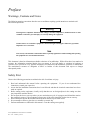
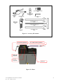
Axiom
Ophthalmic Lens Generator
February 2, 2010
Rev. 1.00
Table of Contents
Preface
Chapter 1: Unpacking Installation and Startup
Chapter 2: User Interface and Controls
Chapter 3: Generating Lenses and Laps
Chapter 4: Setup
Chapter 5: Advanced Setup
Chapter 6: Maintenance
Appendix A: General Specifications
Appendix B: Certifications and Standards
Appendix C: Electrical Diagram
Appendix D: Certificate of Compliance
Preface
Warnings, Cautions and Notes
The following notation conventions alert the user to conditions requiring special attention to maximize safe
and efficient operations.
Warning
Warning notices emphasize that hazardous voltages, currents, temperatures, machine motions or other
conditions could cause personal injury or seriously damage the equipment.
Caution
Caution notices are used where equipment or materials might be damaged or laboratory operations
impaired if care is not taken.
Note
Notes merely call attention to information that is especially significant to understanding and operating
the equipment in a safe and efficient manner.
This document is based on information available at the time of its publication. While efforts have been made to be
accurate, the information contained herein does not purport to cover all details or variations in hardware or
software, nor to provide for every possible contingency in connection with installation, operation, or maintenance.
The manufacturer assumes no obligation of notice to holders of this document with respect to changes
subsequently made.
Safety First
Observe the following precautions to minimize the risk of accidents or injury:
1. Read and understand this manual before operating the equipment. If you do not understand the
instructions, consult your supervisor.
2. Assure that the installation instructions have been followed and that the electrical connections have been
made as required.
3. Before turning on the equipment, visually verify that there are no foreign objects in the cutting area that
may impede the machine motion.
4. Do not open the door or case top unless you are certain that no cycle is in progress and all machine motion
has completely stopped. Do not attempt to bypass any of the safety interlocks for the door or case top.
5. Do not attempt to operate the machine unless the door and case top are both closed.
6. Never attempt to surface a glass lens or a metallic or ceramic lap.
7. Perform maintenance as indicated in this manual. Clean the cutting area regularly.
Axiom Ophthalmic Lens Generator User Manual
Rev. 1.00 - February 2, 2010
5
Axiom Ophthalmic Lens Generator User Manual
Rev. 1.00 - February 2, 2010
6
Chapter 1:
Unpacking, Installation and
Startup
Identifying Components
The following figures identify components and sub-systems of the Axiom Generator referred to in this manual.
Compressed air valve, gage and filter
Touch screen display
Power switch
Door
Emergency Stop button
Start button
Air supply (to mister)
Chuck button
AC power input
Vacuum power outlet
Figure 1.1: Front-left view of case
Axiom Ophthalmic Lens Generator User Manual
Rev. 1.00 - February 2, 2010
7
Display adjustment
handle
Air and water inputs (from mister)
COMM and USB ports
Figure 1.2: Front-right view of case
RS-232 serial
USB (x2)
Ethernet
Video output
Figure 1.3: Ports – detail
Axiom Ophthalmic Lens Generator User Manual
Rev. 1.00 - February 2, 2010
8
Figure 1.4: Accessory Kit contents
Air inlet from generator
Air + water outlet to generator
Water flow
adjustment
Air flow
adjustment
Water fill
Figure 1.5: Mister
Axiom Ophthalmic Lens Generator User Manual
Rev. 1.00 - February 2, 2010
9
Unpacking the Axiom Generator and Vacuum Unit
Caution
The Axiom Generator should be lifted by two people, one on each side of the unit, grasping the base plate
along the sides of the unit. The Axiom is precisely adjusted at the factory prior to shipment. Do not drop it or
subject it to unnecessary shock or jarring.
1. Remove the generator from its wooden shipping pallet by removing the two bolts found on the pallet’s
underside. Use a 13/16” box wrench.
2. Remove the vacuum unit from its carton. Remove accessories from the inside of the canister and install the
large vacuum bag.
Custom Cabinet Assembly (optional)
Perform the following 3 steps if the Axiom custom cabinet was ordered:
1. Remove cabinet and cabinet top from shipping box. Place cabinet top white side down on the floor.
2. Place cabinet upside-down on cabinet top with doors on the same side as the cut-out in the top.
3. Attach cabinet to top with the screws provided. Turn assembled cabinet upright.
Counter-top Preparation
Note
The location selected for the installation of the Axiom Generator should take into account that it requires its own
separate 20A circuit for 115 VAC units, or 10A circuit for 230 VAC units. No other device or equipment should
be powered from this circuit (i.e., from the circuit breaker protecting this circuit.) It also requires compressed air
of at least 80 PSI with a flow rate of up to 1 CF/M.
The mister may be positioned to either side of or behind the generator. It may also be wall mounted. In all cases,
the mister’s base should be at the same level as the base of the generator.
For counter-top installation, prepare the counter-top as follows:
1. Verify that the counter top is at least 30” deep (front to back) and 32” wide and that it has under-clearance
for the vacuum unit and electrical supply lines. Additional space behind or to the side of the Axiom should
be provided if the mister is on the counter. See Figure 1.6.
2. Referring to Figure 1.7, mark a rectangular cutout area positioned and dimensioned as shown in the figure.
The vacuum hose and power cord will pass through this cutout to connect the vacuum unit below to the
generator, thus the supporting structure of the counter must provide clearance for the vacuum unit and its
hoses.
3. Cut out the rectangular area marked in the previous step. Remove any ragged edges with a file or
sandpaper.
Axiom Ophthalmic Lens Generator User Manual
Rev. 1.00 - February 2, 2010
10
Figure 1.6: Generator and mister footprints
Figure 1.7: Counter top layout with cut-out
Axiom Ophthalmic Lens Generator User Manual
Rev. 1.00 - February 2, 2010
11
Generator Installation
Warning
Do not operate the generator unless all shipping restraints have been removed as described below.
Positioning the vacuum unit and generator
The term “bench” in the following refers to either the cabinet top or counter top.
1. Place the vacuum unit under the counter or inside the cabinet aligning its inlet with the bench cut-out.
2. Feed the vacuum power cord up through the cut-out, draping it to the rear of the bench.
3. Turn the vacuum power switch to the ON position. The generator will control the actual cycling of
vacuum power.
4. Place the generator on the bench, aligning the vacuum coupler on its underside with the right side of the
bench cut-out. Lift the generator by grasping the lower edge of the side panels inboard of the feet.
Removing shipping restraints
5. See Figure 1.8 at the end of this chapter. Open the Axiom upper case by grasping beneath the lip in the
front and lifting. Shipping restraints are marked with yellow tags. Remove these tags as the following
steps are performed.
6. Release the lens drive carriage by removing the shipping bracket that is bolted to the base and the carriage
plate.
7. Release the cutter motor carriage by removing the bolt in the block on the right side of the carriage. After
removing the bolt, remove the spacer between the block and cutter motor carriage. Leave the block in
place, as it acts as a carriage stop during operation.
Connecting vacuum hoses and power cord
8. See Figure 1.8. Insert the end of the 2½" flex vacuum hose into the coupler on the bottom of the generator
from below the bench. This connects the hose to the chip chute. Maintaining a gentle curve between the
chip chute and vacuum, connect the other end of the 2½" hose to the vacuum inlet. The vacuum inlet is
the lower hole in the vacuum canister.
9. For optimum suction, cut the 2½" hose to the shortest length possible with a utility knife. The excess hose
may be used to direct the heated exhaust of the vacuum away from the machine. For cabinet installations,
connect the additional large hose from the outlet of the vacuum canister to the boot on the lower left side
of the rear of the cabinet. This hose exhausts the hot air from the cabinet.
10. Plug the vacuum power cord into the socket on the left side of the generator towards the rear.
Attaching compressed air lines
11. The compressed air connection is on the left side of the generator towards the rear. Install the
regulator/filter assembly, found in the accessory kit, by inserting it into the quick-connect bulkhead fitting.
The assembly will snap in place.
12. Attach the quick disconnect onto the end of the air line to be used. The air line can then be pushed on the
male fitting of the regulator/filter assembly.
13. Verify that the regulated line pressure is 80 psi, If the pressure is not 80 psi, adjust the knob on the top of
the regulator/filter assembly.
Attaching the mister
The base of the mister should be level with the mounting bench.
Axiom Ophthalmic Lens Generator User Manual
Rev. 1.00 - February 2, 2010
12
14. Attach the mister’s compressed air feed line. It originates below the pressure regulator on the lower left
side plate of the generator
15. Attach the hose containing air and water feed lines to the connections on the right side of the generator.
16. Fill the reservoir.
Initial power on
Do not turn the Axiom power on until becoming familiar with Chapeter 2:User Interface and Controls
17. Close the case top if it is open. Plug the generator into its dedicated circuit outlet.
18. Toggle the main power switch on the left side of the unit towards the rear. (Position 1)
19. After a few seconds, the processor power-on sequence will be displayed. The door will open and close
and the axes will move to their home positions, and the cutter motor will run briefly.
Figure 1.8: Locations of shipping restraints
Axiom Ophthalmic Lens Generator User Manual
Rev. 1.00 - February 2, 2010
13
Axiom Ophthalmic Lens Generator User Manual
Rev. 1.00 - February 2, 2010
14
Chapter 2: User Interface and Controls
Using the touch-screen display
Caution
Sharp objects (pencil point, paper clip, etc.) may damage or tear the surface of the touch-screen display.
The screen is designed to activate with a light finger tap. A stylus as found in office supply stores may also
be used if desired.
Note
If necessary, the display screen may be cleaned with a micro-fiber cloth such as is used to clean eyeglasses.
A soft cloth slightly dampened with water may be used to remove excess spots. Do not clean the display unless
the generator has been turned off.
Screen Objects
The Axiom screen displays objects of the following types:
• Data entry field: screen location where numeric or text data may be entered or changed. The currently
selected field is shown in yellow.
• Data display-only field: location where numeric or text data is displayed, but not modifiable.
• Binary status indicator: location where status is displayed (such as door open vs. door closed).
• Selection field: location where a choice may be made among several possibilities.
• Control button: location where an action is initiated (e.g., screen change, machine start/stop, etc.).
• Keypad: simulated numeric or alphanumeric keypad.
• Graphic: a picture providing helpful user information (i.e., representation of generated shape.)
• Scroll bar: means to select viewing location within a large file (such as a log file).
Selecting a screen object
A data entry field must be selected prior to entering or changing data. To select a field, tap it once and observe
its color change. For screens with multiple data entry fields, they may be selected in sequence by tapping the
UP or DOWN arrow keys in the keypad. (The sequence is fixed and is not changeable by the user.)
Entering numeric data
1. Select the desired data entry field.
2. Optionally tap the CLEAR key to erase any prior entry. (This operation may not be undone.)
3. Press numeric keys to enter the desired value. Numeric values have a pre-set number of decimal fraction
digits. Observe how a numeric value fills in from the right as each digit is tapped. (Example: An entry
with two decimal places whose desired value is 5 must be entered as 5 0 0).
4. Use the CLEAR key to start over in case of error.
5. Use the +/- key to change the sign. It may be tapped prior to, during, or after entering the digits.
Complete the data entry by tapping the ENTER key, or by selecting a different screen
object.
Axiom Ophthalmic Lens Generator User Manual
Rev. 1.00 - February 2, 2010
15
Selecting Alternatives
There are several types of data selection fields:
• Check box: turns a selection on or off. Tap the check box to toggle its status.
• Radio button: selects one from among several choices. Tap the desired choice. Radio buttons that are
grouped together are mutually exclusive; only one may be selected at a time.
• Toggle: selects one from among several choices. Each tap of the field will display the next selection.
• Scroll bar: Tap either the up-arrow or down-arrow to move the view window one line, or lightly press and
hold the square slider and move it up or down for larger movements. (The view window will not change
until the slider is released.)
Navigating among screens
• From the Job Screen (displayed at startup), tap within the logo area in the upper left to access the screen
selection control buttons. These buttons are usually arrayed across the top or down the left side of a
screen.
• Tap the control button labeled with the desired screen, e.g., SETUP. The screen menu is a hierarchy, thus
selection of a screen will generally expose additional controls buttons for accessing other screens.
• Tap the EXIT button to return to the Job Screen.
• When a selection requires choosing among several options, a new screen showing the available options
may be displayed.
Using Mechanical Buttons and Switches
The Axiom generator has a number of mechanical buttons and switches affecting machine operation. These
are described in the following table.
Control
Description and Location
Function
E-Stop
•
Large bright red button
with yellow surround.
Case top, lower right.
Emergency stop. Causes current cycle and all motion to stop
immediately. The display shows the red E-Stop screen. Cancel
the E-Stop by turning the red button clockwise until it pops
outward. At this time, the air pressure is removed from the door
mechanism so it can be manually opened if desired. Cancelling the
E-Stop causes the RESUME button to appear on the screen. Tap
RESUME to cause the carriages to return to their home position.
Green illuminated
round button.
Case top, lower left.
Initiates a cycle. Duplicates function of the START control button
on the touch screen. Pressing the button has no effect unless it is
illuminated. While a generating cycle is in progress, the Start
button flashes on/off.
•
Blue illuminated round
button.
Case top, lower left.
With each press, causes the pneumatic chuck to cycle between
closed (clamping) or open (not clamping). The button is
illuminated when it is safe to open or close the chuck. Pressing the
Chuck button has no effect if it is not illuminated.
•
•
Black rocker switch.
Left side rear.
Turns ON or OFF the main AC power to the generator and
vacuum.
•
Start
•
•
Chuck
Power
ON/OFF
•
Axiom Ophthalmic Lens Generator User Manual
Rev. 1.00 - February 2, 2010
16
Cutter
Motor
ON/OFF
•
•
Black rocker switch.
Inside case right front
atop black motor
controller chassis.
Enables the cutter motor when ON. Disables the cutter motor
when OFF. This switch is used primarily by maintenance staff.
Vacuum
power
control
•
•
3-way rocker switch
Underside of case top
adjacent to left casetop hinge
Turns vacuum ON (up position),
Turns vacuum OFF (center position) or
AUTOMATIC operation within cycle (down position).
Select the AUTOMATIC position for normal operations.
Axiom Ophthalmic Lens Generator User Manual
Rev. 1.00 - February 2, 2010
17
Axiom Ophthalmic Lens Generator User Manual
Rev. 1.00 - February 2, 2010
18
Chapter 3:
Generating Lenses and Laps
Process Overview
The process steps in generating a lens or lap are essentially similar, with a few minor exceptions. They are:
• Enter or download data for the job.
• Visually verify key values to minimize risk of scrap or equipment damage.
• Chuck lens or lap.
• Execute generating cycle.
• Unchuck lens or lap.
The Job Screen
The Job Screen is the primary user interface during the lens and lap generation process. Use the Job Screen to
enter, download and display data for the current lens or lap being generated, and to display status during the
generating process. On the lower-left of the Job Screen are two control buttons labeled Lens and Lap.
Tapping the Lens or Lap control button will configure the information on the Job Screen for generating the
selected object. Figure 3.1 shows the lens-generation Job Screen. Figure 3.2 shows the lap-generation Job
Screen. A table follows each figure that describes the screen’s graphic elements.
When either Job Screen is displayed, it includes the Axiom logo along the left edge. Tap anywhere within the
logo to reveal the control buttons for accessing the Setup and Statistics screens.
Figure 3.1: Lens-generating Job Screen
Axiom Ophthalmic Lens Generator User Manual
Rev. 1.00 - February 2, 2010
19
Graphic Elements on the Lens-generating Job Screen
Screen Graphic Item
Logo
Remarks
•
Tap to display screen navigation controls.
•
When returning to the Job Screen from another screen, the logo will again be displayed.
•
The logo is not displayed in figure 3.1.
•
Tap to navigate to main Setup Screen. See Chapter 4: Setup.
•
Tap to navigate to the Statistics Screen described later in this chapter.
•
Tap to display the lens-generating Job Screen configuration.
•
Tap to display the lap-generating Job Screen configuration.
Setup button
Statistics
Lens
Lap
Generator Data
Note: data shown in the figure is not necessarily representative of actual generator data.
Base Curve
•
Tap to enter/change base curve to be generated on rear surface.
•
Max: +6.00D Min: -30.00D
Cross Curve
•
Tap to enter/change cross curve to be generated on rear surface.
•
Max: +6.00D Min: -30.00D
Center Thickness
•
Tap to enter/change center thickness to be generated (in mm).
•
Does not include any takeoff from fining and polishing.
Layout Axis
•
Tap to enter/change the angle from the seg line to the cylinder line (in degrees)
•
Max: 180
Min: 0
Prism
•
Tap the field to enter/change the actual (uncompensated) prism value to be generated (in Diopters).
•
Max: +20.00D Min: +0.00D
Prism Axis
•
Tap the field to enter/change the orientation of the prism power (in degrees) relative to the layout
line.
•
Max: 180
Min: 0
Crib Diameter
•
Tap the field to enter/change the Crib diameter (in mm).
•
Max: 80 mm
Min: 50 mm
•
Enter 0 to suppress cribbing.
•
Crib diameter should exceed block diameter by at least 2 mm
Pin Bevel
•
Tap the field to enable or disable pin (safety) bevel.
•
Bevel depth established via setup value. See Chapter 4: Setup.
Blank Data
Material
•
Tap the field to display the Material Selection screen. Tap desired material to select.
•
Available materials are specified via setup values. See Chapter 4: Setup.
•
Material will default to value from previous job.
•
Never attempt to cut a glass lens blank.
Front Curve
•
Tap the field to enter/change the lens blank’s true front curve (in Diopters).
•
Max: +30.00D Min: -6.00D
Back Curve
•
Tap the field to enter/change the lens blank’s true back curve (in Diopters).
•
Max: +30.00D Min: -6.00D
Edge Thickness
•
Tap the field to enter/change the thickness of blank edge before generating (in mm).
•
Max: 30 mm
Min: 1 mm
Diameter
•
Tap the field to enter/change the diameter of lens blank prior to cribbing or generating (in mm)
•
Max: 90 mm
Min: 35 mm
•
Max if the blank is to be cribbed: 85 mm
Block Name
•
Tap the field to display Block Selection screen.
•
Tap desired block to select. available block types specified via setup values. See Chapter 4: Setup.
•
Geometric Center blocking is recommended.
•
Visually verify lens is blocked with specified type block before chucking.
Cycle Information
Cutter Load
•
Bar graph indicates approximate loading on cutter motor.
•
If a gradually increasing load is observed, this may indicate a dull cutter.
•
Display only graphic.
Cycle Status
•
Bar graph indicates approximate progress through cycle.
•
Timer displays estimated time remaining in cycle.
•
Display only fields.
Message area
•
Displays informational and error messages.
Axiom Ophthalmic Lens Generator User Manual
Rev. 1.00 - February 2, 2010
20
Figure 3.2: Job Screen – lap generation configuration
Graphic Elements on the Lap-generating Job Screen
Screen Graphic Item
Logo
Setup button
Statistics
Lens
Lap
Generator Data
Base Curve
Cross Curve
Pad Thickness
Blank Data
Lap Manufacturer
Lap Type
Base Curve
Cross Curve
Diameter
Center Thickness
Operation
•
Tap to display screen navigation controls.
•
When returning to the Job Screen from another screen, the logo will again be displayed.
•
The logo is shown in Figure 3.2. Tap it to cause Setup and Statistics controls to be displayed.
•
Tap to navigate to main Setup Screen. See Chapter 4: Setup.
•
Tap to navigate to the Statistics Screen described later in this chapter.
•
Tap to display the lens-generating Job Screen configuration.
•
Tap to display the lens-generating Job Screen configuration.
•
•
•
•
•
•
•
•
•
Tap to enter/change the base curve to be generated.
Max: +30.000D Min: -6.000D
Note 3 decimal fraction digits.
Tap to enter/change the cross curve to be generated .
Max: +30.000D Min: -6.000D
Note 3 decimal fraction digits.
Tap to enter/change the pad thickness (in mm).
Use compensated value if pad is compensated.
Max: 3.00 mm
Min: 0.00mm
Usual default is 0.46 mm
•
•
•
•
•
•
•
•
•
•
•
•
•
•
Tap the field to display Lap Manufacturer Selection Screen.
Tap desired manufacturer to select.
Available manufacturers specified via setup values. See Chapter 4: Setup.
Lap cycle data is specified via Lap Screen.
Axiom choses optimum lap from specified manufacturer to achieve required curves.
Displays optimum lap selected by Axiom. A different lap type may be entered.
Displays true base curve of lap prior to cutting (in Diopters).
Max: +30.00D Min: -30.00D
Displays true cross curve of lap prior to cutting (in Diopters).
Max: +30.00D Min: -30.00D
Diameter of lap (in mm)
Max: 90 mm
Min: 40 mm
Tap to enter/change center thickness of uncut lap (in mm).
See figure 3.3 for measurement methodology.
Axiom Ophthalmic Lens Generator User Manual
Rev. 1.00 - February 2, 2010
21
Center Cuttable
Cycle Information
Cutter Load
Cycle Status
Get Best Lap
Message Area
•
•
•
Tap to enter/change desired material removal. Usually computed by Axiom.
Typically 1-3 mm when the lap blank base curve is shallower than the generated curve, and 4-8
mm when the lap blank base curve is steeper than the generated curve.
Should always be at least 1 mm.
•
•
•
•
•
•
•
•
Bar graph indicates approximate loading on cutter motor.
Gradually increasing load may indicate dull cutter.
Display only
Bar graph indicates progress through cycle.
Timer displays time remaining in cycle.
Display only
Selects available lap requiring the least amount of material removal.
Displays informational and error messages
Figure 3.3: Measuring lap center thickness
Informational Job Screen Icons
A number of informational icons are displayed along the lower edge of the Job Screen. These are shown and
described in the following table.
Icon
Description
Icon
Description
The network is enabled and operating
properly.
System time
A network error has occurred.
A USB memory drive is installed.
The network is not connected.
The installed USB memory drive may be
used to update software
More than 90% of expected cutter life
remains. (Black icon)
Maintenance action is required.
10 % of cutter life remains. (Orange icon)
A system error has occurred.
Cutter should be replaced. (Red icon)
A message is available.
Axiom Ophthalmic Lens Generator User Manual
Rev. 1.00 - February 2, 2010
22
Downloading Job Data
To download job data from a host computer, the Axiom generator must be configured for data communication
(See Chapter 4: Setup).
1. Enter the job number (sometimes called the tray number) into the Job Number field on the Job Screen.
Tap Enter to initiate the data transfer. Alternatively, if the Axiom is equipped with a barcode reader, the
job number may be scanned in. (Pressing Enter is not required if the job number is entered via barcode
scan.)
2. After several seconds, the job data will appear on the Job Screen. A “contour map” image of the generated
lens will be displayed in the upper right of the screen.
3. Visually verify that the downloaded data contains no errors.
4. Manually change any values as needed.
Manually Entering Job Data
Job data may be entered manually by selecting each of the fields in the Job Screen, in turn, and entering the
data for each field.
Generating a Lens
Warning
Under no circumstances should an attempt be made to generate a glass lens blank. Doing so may result in
serious damage to the cutter and other parts of the Axiom mechanism. Only resin lenses may be generated.
Caution
Prior to generating a lens, be sure that the block affixed to the lens is correctly identified on the Job Screen.
If the diameter of the affixed block is larger than the block shown on the Job Screen, the cutter may collide
with the block, potentially damaging the cutter, the block and the workpiece.
Caution
Do not attempt to open the case top or the door while the cycle is in progress. If the cycle must be interrupted,
press the red E-stop button which causes an immediate yet controlled cycle stop. Opening the case top or the door
will also cause the cutter and all carriage motion to stop, however a controlled restart may not be possible.
Axiom Ophthalmic Lens Generator User Manual
Rev. 1.00 - February 2, 2010
23
1. Hold the blocked lens in the right hand with the segment (if any) down. The chuck will have rotated to
accept the lens in this orientation.
2. Place the block into the chuck and rotate it slightly until the pins in the chuck engage the block.
3. Press the Chuck button on the lower left of the case front.
4. Tap the large green Start control button on the Job Screen to initiate the generating cycle. Alternatively,
the Start button on the lower-left case front may be pressed.
5. The status information displayed at the top-center of the Job Screen provides an indication of cycle
progress.
6. At the end of the cycle, all motors stop and the door opens automatically.
7. Press the Chuck button to remove the generated lens from the chuck.
Generating a Lap
Warning
Under no circumstances should an attempt be made to generate a metallic or ceramic lap. Doing so may result in
serious damage to the cutter and other parts of the Axiom mechanism.
Caution
Do not attempt to open the case top or the door while the cycle is in progress. If the cycle must be interrupted,
press the red E-stop button which causes an immediate yet controlled cycle stop. Opening the case top or the door
will also cause the cutter and all carriage motion to stop, however a controlled restart may not be possible.
Note
If lens data has been entered prior to entering the Job Screen for cutting laps, the data displayed for the lap
will allow a lap to be generated which matches the lens data.
1. Hold the lap in the right hand and place the lap holder into the chuck. Rotate it until the pins in the chuck
engage the lap holder.
2. Press the Chuck button on the lower left of the case front.
3. Tap the large green Start control button on the Job Screen to initiate the generating cycle. Alternatively,
the Start button on the lower left case front may be pressed.
4. The status information displayed at the top-center of the Job Screen provides an indication of cycle
progress.
5. At the end of the cycle, all motors stop and the door opens automatically.
6. Press the Chuck button to remove the generated lap from the chuck.
The Statistics Screen
The Statistics Screen is accessed from the Job Screen. First tap the Axiom logo on the left side of the screen if
it is displayed. This will reveal buttons for accessing the Setup Screen and the Statistics Screen. The Statistics
Screen shows the number of times specific elements of the generation cycle have occurred. The totals
displayed may be reset by service personnel, but not by the end user.
Axiom Ophthalmic Lens Generator User Manual
Rev. 1.00 - February 2, 2010
24
Chapter 4: Setup
Setup Overview
The Axiom generator maintains a large amount of data to optimize its performance and to customize it for the
specific lab in which it is installed. For example, setup data defines the material removal rates for the various
lens and lap materials, geometric properties of blocks and cutting tools, and a variety of user preferences. It
defines the parameters for data communications if the Axiom is connected to a host computer. Service
personnel may access highly technical data, such as values to fine tune the motion control of the motors.
The Axiom Setup Screens also provide access to the generator’s Advanced Setup Screen, which is used during
Calibration, Maintenance and Diagnostics. The Advanced Setup facilities are treated separately in the
following chapter.
The Main Setup Screen
Figure 4.1 shows the main setup screen. The table following the figure describes the graphic elements
displayed on the Setup Screen.
Figure 4.1: Main Setup Screen (showing “About” information)
Axiom Ophthalmic Lens Generator User Manual
Rev. 1.00 - February 2, 2010
25
Graphic Elements on the Main Setup Screen
Graphic Item Name
Remarks
Logo
•
Left side. Display only.
Screen Navigation Buttons (across top of Setup Screen)
Preferences
•
Tap to navigate to the Preferences Screen.
Materials/Tools
•
Tap to navigate to the Materials/Tools Screens (to specify lenses, laps, blocks and cutters).
Maintenance
•
Tap to navigate to Maintenance Screen (see Chapter 6: Maintenance and Data).
Communications
•
Tap to navigate to Communication Screen (to specify communication parameters).
Advanced
•
Tap to navigate to the Advanced Setup Screen (for diagnostics, event logging, other functions)
•
Advanced Setup is discussed in Chapter 5.
About
•
Tap to show hardware and software identifying numbers. The data on the About Screen is
displayed when first entering the Setup Screen.
Exit
•
Tap to return to Job Screen
Read-only Machine Identification Data
(This data is also shown on the About Screen)
Product Serial Number
•
Value entered by service personnel.
Company Name
•
Value entered by service personnel.
Current User
•
See “Login” below.
Software Version
•
Value established when software is loaded or updated.
Motion Card Firmware
•
Value entered by service personnel.
Version
Motion Card
•
Value entered by service personnel.
Hardware Version
Motion Card Frequency
•
Value entered by service personnel.
User Login
Login
•
Tap the field to display the user Login Screen
•
Enter administrator password to gain access to certain screens as specified by the Permissions
Screen.
•
Non-administrators may operate the Axiom, but have restricted access to setup values.
Preferences Screen
Figure 4.2 shows the Preferences Screen. The table following the figure describes the graphic elements
displayed on the Preferences Screen.
Figure 4.2: Preferences Screen
Axiom Ophthalmic Lens Generator User Manual
Rev. 1.00 - February 2, 2010
26
Graphic Elements on the Preferences Screen
Field Name
Tool Index
Ring Index
Installed Cutter
Communications
Advanced
About
Exit
Remarks
•
Index of refraction to which curves on tools (laps) are generated.
•
Typically 1.53.
•
Index of refraction used in computation of prism.
•
Value should match rings used in the lab, if any. Default value is 1.53.
•
Prism rings are neither recommended nor necessary when using the Axiom generator.
•
Identifies cutter installed in machine.
•
Select cutters via Material/Tools Screen.
•
Tap to navigate to Communication Screen (to specify communication parameters).
•
Tap to navigate to the Advanced Setup Screen (for diagnostics, event logging, other functions). See
Chapter 4: Advanced Setup.
•
Tap to display machine and software identifying numbers.
•
Same data as displayed on Main Setup Screen.
•
Tap to return to Job Screen
Material/Tools Screens
There are four screens available for recording data about materials and tools: A Lens Material Screen, a Lap
Material Screen, a Blocks Tool Screen and a Cutter Tool Screen.
Lens Material Screen
Figure 4.3 shows the Lens Materials Screen. The table following the figure describes the graphic elements
displayed on the Material/Tools Screen.
Figure 4.3: Lens Material Screen
Axiom Ophthalmic Lens Generator User Manual
Rev. 1.00 - February 2, 2010
27
Graphic Elements on the Lens Material Screen
Graphic Element
Remarks
Name
Screen Navigation Buttons (across top of Setup Screen)
Preferences
•
Tap to navigate to the User Preferences Screen.
Materials/Tools
•
Tap to navigate to the Materials/Tools Screens (to specify lenses, laps, blocks and
cutters).
Maintenance
•
Tap to navigate to Maintenance Screen (for software update, calibration, system
backup, time).
Communications
•
Tap to navigate to Communication Screen (to specify communication parameters).
Advanced
•
Tap to navigate to the Advanced Setup Screen (for diagnostics, event logging, other
functions)
About
•
Tap to display machine and software identifying numbers
Exit
•
Tap to return to Job Screen
Lens, Lap, Block and Tool Selection Buttons (left edge of Screen)
Lens
•
Tap to display lens material properties grid. The upper left of the grid shows the
currently-selected material.
•
To select a different existing material, tap the upper-right of lens material properties
grid. A materials matrix of available materials is displayed. Tap the desired
material.
•
To change the name of an existing material, tap the current material name in the
upper-left of the lens material properties grid, press CLEAR, enter the new name.
[The prior name will no longer be a valid material and numeric data associated with
the old name will now be associated with the new name].
•
To add a new material, select an empty element of the materials matrix. When the
Lens Material Screen re-appears, enter the name of the new material in the upper-left
of the material properties grid.
•
In the material properties grid, enter values for Takeoff, Speed and Spiral
Separation:
- Takeoff: amount of material removal in one pass (i.e., depth of cut, in mm).
- Speed: linear speed of tool relative to lens surface (mm/sec).
- Spiral Separation: radial distance between neighboring spiral ridges (mm).
•
The Takeoff, Speed and Spiral Separation may be specified for each generation
phase:
- Rough: first pass affecting maximum material removal.
- Finish: final pass affecting smooth finish.
- Cribbing: pre-generation reduction in diameter of lens blank.
- Pin Bevel: bevel cut along edge of lens for safer handling, reduced chipping, and
improved fining and polishing.
Lap
•
Tap to display the Lap Material Screen (on following page).
Block
•
Tap to display the Blocks Tool Screen (on following page).
Cutter
•
Tap to display the Cutter Properties Screen (on following page).
Axiom Ophthalmic Lens Generator User Manual
Rev. 1.00 - February 2, 2010
28
Lap Material Screen
Data describing laps in the Axiom generator are maintained in a lap library and are organized first by
manufacturer, then, and for each manufacture, by type. The lap type defines the geometry (curves, thickness,
diameter, etc.) of a specific lap. When job data is entered for generating a lens, the Axiom automatically
selects the lap which can be generated with a minimum amount of material removal.
Figure 4.4 shows the Lap Materials Screen. The table following the figure describes the graphic elements
displayed on the screen.
Figure 4.4: Lap Material Screen
Graphic Elements on the Lap Material Screen
Graphic Element Name Remarks
Screen Navigation Buttons (across top of Setup Screen)
Preferences
•
Tap to navigate to the User Preferences Screen.
Materials/Tools
•
Tap to navigate to the Materials/Tools Screens (to specify lenses, laps, blocks and cutters).
Maintenance
•
Tap to navigate to Maintenance Screen (for software update, calibration, system backup, time).
Communications
•
Tap to navigate to Communication Screen (to specify communication parameters).
Advanced
•
Tap to navigate to the Advanced Setup Screen (for diagnostics, event logging, other functions)
About
•
Tap to display machine and software identifying numbers
Exit
•
Tap to return to Job Screen
Lens, Lap, Block and Tool Selection Buttons (left edge of Screen)
Lens
•
Tap to display lens material properties grid (described above).
Lap
•
Tap to display laps properties grid. The upper left of the grid shows the currently-selected lap
manufacturer. The center-left of the grid shows the currently-selected lap type.
•
To select a different existing manufacturer, tap the upper-right of laps properties grid. A
manufacturer matrix of existing lap manufacturers is displayed. Tap the desired manufacturer.
•
To change the name of an existing manufacturer, tap the current manufacturer name in the upperleft of the laps properties grid, press CLEAR, enter the new name. [The prior name will no longer
be a valid manufacturer, and numeric data associated with the old name will now be associated
with the new name].
•
To add a new manufacturer, tap the upper-right of laps properties grid and then select an empty
element of the manufactureer matrix. When the Lap Material Screen re-appears, enter the name of
Axiom Ophthalmic Lens Generator User Manual
Rev. 1.00 - February 2, 2010
29
•
•
•
•
•
•
•
Block
Cutter
•
•
the new manufacturer in the upper-left of the laps properties grid.
To select a different existing lap type, tap the center-right of laps properties grid. A type matrix of
existing laps from the selected manufacturer is displayed. Tap the desired type.
To change the name of an existing type, tap the current type name in the center-left of the laps
properties grid, press CLEAR, enter the new type name. [The prior name will no longer be a valid
type and numeric data associated with the old name will now be associated with the new name].
To add a new type, tap the center-right of laps properties grid. select an empty element of the type
matrix. When the Lap Material Screen re-appears, enter the name of the new type in the center-left
of the laps properties grid.
In the upper half of the laps properties grid, enter values for Takeoff, Speed, Spiral Separation and
Skim Cut:
- Takeoff: amount of material removal in one pass (i.e., depth of cut, in mm).
- Speed: linear speed of tool relative to lap surface (mm/sec).
- Spiral Separation: radial distance between neighboring spiral ridges (mm).
- Skim Cut: Smoothing pass in finish cutting phase.
The Takeoff, Speed and Spiral Separation may be specified for each generation phase:
- Rough: first pass affecting maximum material removal.
- Finish: final pass affecting smooth finish.
In the lower half of the laps properties grid, enter geometric values defining the lap type. The user
should know the meaning of all the fields with the following possible exceptions;
- Center Cuttable: maximum amount of material which may be removed at the center of the lap.
- Identifier (LAPM): A downloaded identifier for the lap.
If the user has created one or more custom laps, these may be added to library either by choosing a
manufacturer with the desired material removal properties, or by selecting “(others)” as the
manufacturer. The lap type may be “user-defined.”
Tap to display the Blocks Tool Screen (described below)
Tap to display the Cutter Properties Screen: (described below).
Blocks Tool Screen
Figure 4.5 shows the Blocks Tool Screen. The table following the figure describes the graphic elements
displayed on the screen.
Figure 4.5: Blocks Tool Screen
Axiom Ophthalmic Lens Generator User Manual
Rev. 1.00 - February 2, 2010
30
Graphic Elements on the Blocks Tool Screen
Graphic Element Name Remarks
Screen Navigation Buttons (across top of Setup Screen)
Preferences
•
Tap to navigate to the User Preferences Screen.
Materials/Tools
•
Tap to navigate to the Materials/Tools Screens (to specify lenses, laps, blocks and cutters).
Maintenance
•
Tap to navigate to Maintenance Screen (for software update, calibration, system backup, time).
Communications
•
Tap to navigate to Communication Screen (to specify communication parameters).
Advanced
•
Tap to navigate to the Advanced Setup Screen (for diagnostics, event logging, other functions)
About
•
Tap to display machine and software identifying numbers
Exit
•
Tap to return to Job Screen
Lens, Lap, Block and Tool Selection Buttons (left edge of Screen)
Lens
•
Tap to display lens material properties grid (described above).
Lap
•
Tap to display lap material properties grid (described above).
Block
•
Tap to display block properties grid. The upper left of the grid shows the currently-selected block
manufacturer. The center-left of the grid shows the currently-selected block type.
•
To select a different existing manufacturer, tap the upper-right of block properties grid. A
manufacturer matrix of existing lap manufacturers is displayed. Tap the desired manufacturer.
•
To change the name of an existing manufacturer, tap the current manufacturer name in the upperleft of the block properties grid, press CLEAR, enter the new name. [The prior name will no
longer be a valid manufacturer, and numeric data associated with the old name will now be
associated with the new name].
•
To add a new manufacturer, tap the upper-right of block properties grid and then select an empty
element of the manufacturer matrix. When the Blocks Tool Screen reappears, enter the name of the
new manufacturer in the upper-left of the block properties grid.
•
To select a different existing block type, tap the center-right of block properties grid. A type matrix
of existing blocks from the selected manufacturer is displayed. Tap the desired type.
•
To change the name of an existing type, tap the current type name in the center-left of the block
properties grid, press CLEAR, enter the new type name. [The prior name will no longer be a valid
type and numeric data associated with the old name will now be associated with the new name].
•
To add a new type, tap the center-right of block properties grid. Select an empty element of the
type matrix. When the Blocks Tool Screen re-appears, enter the name of the new type in the centerleft of the block properties grid.
•
In the upper half of the block properties grid, enter a values for Axis correction. This is the
number of degrees by which the zero position of the block differs from the horizontal.
•
In the lower half of the block properties grid, enter geometric values defining the block type.
NOTE: these values are generally specified by the block manufacturer.
- Block Diameter: maximum diameter, including wax or alloy
- Block Diameter for SAG: dependent on manufacturer.”
- Block Thickness: distance from face of block contacting lens to the face contacting the chuck.
Cutter
•
Tap to display the Cutter Properties Screen: (described below).
Axiom Ophthalmic Lens Generator User Manual
Rev. 1.00 - February 2, 2010
31
Cutters Tool Screen
Figure 4.6 shows the Cutters Tool Screen. The table following the figure describes the graphic elements
displayed on the screen.
Figure 4.6: Cutter Tool Screen
Graphic Elements on the Cutters Tool Screen
Graphic Element Name Remarks
Screen Navigation Buttons (across top of Setup Screen)
Preferences
•
Tap to navigate to the User Preferences Screen.
Materials/Tools
•
Tap to navigate to the Materials/Tools Screens (to specify lenses, laps, blocks and cutter).
Maintenance
•
Tap to navigate to Maintenance Screen (for software update, calibration, system backup, time).
Communications
•
Tap to navigate to Communication Screen (to specify communication parameters).
Advanced
•
Tap to navigate to the Advanced Setup Screen (for diagnostics, event logging, other functions).
About
•
Tap to display machine and software identifying numbers.
Exit
•
Tap to return to Job Screen.
Lens, Lap, Block and Tool Selection Buttons (left edge of Screen)
Lens
•
Tap to display lens material properties grid (described above).
Lap
•
Tap to display laps material properties grid (described above).
Block
•
Tap to display the blocks properties grid (described above).
Cutter
•
Tap to display cutter properties grid. The upper left of the grid shows the currently-selected block
cutter. The upper-left of the grid shows the currently-selected cutter name.
•
To select a different existing cutter, tap the upper-right of cutter properties grid. A cutter matrix of
existing cutter is displayed. Tap the desired cutter.
•
To change the name of an existing cutter, tap the current cutter name in the upper-left of the cutter
properties grid, press CLEAR, enter the new name. [The prior name will no longer be a valid
manufacturer, and numeric data associated with the old name will now be associated with the new
name].
•
To add a new cutter, tap the upper-right of cutter properties grid and then select an empty element
of the cutter matrix. When the Cutters Tool Screen re-appears, enter the name of the new cutter in
the upper-left of the cutters properties grid.
•
In the cutters properties grid, enter geometric data for the cutter: Radius and length.
NOTE: These values are generally specified by the cutter manufacturer.
Axiom Ophthalmic Lens Generator User Manual
Rev. 1.00 - February 2, 2010
32
Communications Setup Screen
There are three communications setup screens shown in Figures 4.7 – 4.9. These are used to set up serial
communications, Ethernet communications, and to set DCS options. The tables following the figures describe
the graphic elements displayed on the screens.
Serial Communications Setup Screen
Figure 4.7 shows the Serial Communications Setup Screen. The table following the figure describes the
graphic elements displayed on the screen.
Figure 4.7: Serial Communications Setup Screen
Graphic Elements on the Serial Communications Setup Screen
Graphic Screen Element
Remarks
Screen Navigation Buttons (upper-left of screen)
Ethernet
•
Tap to display Ethernet setup.
Serial Port
•
Tap button to display Serial Port Setup
DCS Options
•
Tap to display DCS Setup Data
Serial Communication Parameters
Note: except for bits-per-second (baud rate) all values must be specified as shown in Figure 4.7. The host computer port must be
configured to match the Axiom’s serial port
Bits per second
•
Communication data rate
•
19,200 is recommended. Higher rates may be used for short runs (<50’) of high quality cable.
Data bits
•
8
Parity
•
None
Stop Bits
•
1
Flow control
•
None
Axiom Ophthalmic Lens Generator User Manual
Rev. 1.00 - February 2, 2010
33
Ethernet Communications Setup Screen
Figure 4.8 shows the Ethernet Communications Setup Screen. The table following the figure describes the
graphic elements displayed on the screen.
Figure 4.8: Ethernet Communications Setup Screen
Graphic Elements on the Ethernet Communications Setup Screen
Graphic Screen Element
Remarks
Screen Navigation Buttons (upper-left of screen)
Ethernet
•
Tap to display Ethernet setup.
Serial Port
•
Tap button to display Serial Port Setup
DCS Options
•
Tap to display DCS Setup Data
Ethernet Communication Parameters
Note: These values should be established by someone familiar with the networking requirements in the facility where the Axiom is
deployed.
Axiom Ophthalmic Lens Generator User Manual
Rev. 1.00 - February 2, 2010
34
DCS Services Setup Screen
Figure 4.9 shows the DCS Services Setup Screen.
Figure 4.9: DCS Services Setup Screen
The Axiom generator communicates with host computers and other optical devices using the Data
Communications Standard (DCS) promulgated by the Vision Council. This standard allows the use of both
Ethernet and serial communications. Use this screen to select one or both of these modalities, or to disable
communications entirely. The preferred modality is Ethernet. If this modality is not supported by a device
with which the Axiom must communicate, the serial modality may be used.
About Screen
This screen is automatically displayed when first entering the Main Setup Screen. (See Figure 4.1)
Axiom Ophthalmic Lens Generator User Manual
Rev. 1.00 - February 2, 2010
35
Axiom Ophthalmic Lens Generator User Manual
Rev. 1.00 - February 2, 2010
36
Chapter 5:
Advanced Setup
Advanced Setup Overview
Caution
Data accessed via the Advanced Setup facility is intended for users with a high degree of familiarity
with the Axiom Generator, or users under the supervision of service personnel.
Like the Main Setup functions described in Chapter 4, the Advanced Setup functions provide access to data
used to optimize the Axiom’s performance and to customize it for the specific lab in which it is installed.
However, Advanced Setup data is less frequently viewed or modified. The Advanced Setup items discussed
in this chapter are:
• Advanced Setup Screen (Figure 5.1)
• Diagnostics Screen (Figure 5.2)
• Calibration Screen (figure 5.3)
• Servo Screen (Figure 5.4)
• Mechanical Test Screen (Figure 5.5)
• Touchscreen Calibration Screen
The Advanced Setup Screen
Figure 5.1 shows the Advanced Setup screen. The table following the figure describes the graphic elements
displayed on the Setup Screen.
Figure 5.1: Advanced Setup Screen
Axiom Ophthalmic Lens Generator User Manual
Rev. 1.00 - February 2, 2010
37
Graphic Elements on the Advanced Setup Screen
Button Name
Remarks
Screen Navigation Buttons (across top of Setup Screen)
Preferences
•
Tap to navigate to the User Preferences Screen.
Materials/Tools
•
Tap to navigate to the Materials/Tools Screens (see Chapter 4: Setup).
Maintenance
•
Tap to navigate to Maintenance Screen (described in Chapter 6: Maintenance and Data).
Communications
•
Tap to navigate to Communication Screen (see Chapter 4: Setup).
Advanced
•
Described in this chapter.
About
•
Tap to display machine and software identifying numbers (see Chapter 4: Setup).
Exit
•
Tap to return to Job Screen
Function Selection Buttons (vertical array at upper-left of screen)
Log Viewer
•
System event log is displayed when initially entering Advanced Calibration Screen.
•
Use scroll bar at right of display to scroll through log.
•
Log information is largely for use of service personnel.
Diagnostics
•
Tap to view Diagnostic Screen (described in following section).
Calibration
•
Tap to view Calibration Screen (described later in this chapter.)
Servos
•
Tap to view Servo Screen (described later in this chapter).
Mechanical Test
•
Touch Screen Calibration •
Tap to view Touch Screen Calibration Screen.
•
Tap indicated button to begin calibration.
•
Tap calibration points displayed on screen.
Diagnostics Screen
The Diagnostics Screen allows the user to manually exercise the axis servo motors, to display the encoder
counts and position of each axis, to view the status of the input/output points and to actuate mechanisms such
as the chuck, door, and mister. The features available on the Diagnostic Screen are generally used under
guidance from service personnel. Figure 5.2 shows the Diagnostics Screen. The table following the figure
describes the graphic elements displayed on the Diagnostics Screen.
Figure 5.2: Diagnostics Screen
Axiom Ophthalmic Lens Generator User Manual
Rev. 1.00 - February 2, 2010
38
Graphic Elements on the Diagnostics Screen
Element Name
Remarks
Screen Navigation Buttons (across top of the screen)
Preferences
•
Tap to navigate to the User Preferences Screen.
Materials/Tools
•
Tap to navigate to the Materials/Tools Screens (see Chapter 4: Setup).
Maintenance
•
Tap to navigate to Maintenance Screen. (see Chapter 6: Maintenance and Data)
Communications
•
Tap to navigate to Communication Screen (to specify communication parameters).
Advanced
•
Described in this chapter.
About
•
Tap to display machine and software identifying numbers
Exit
•
Tap to return to Job Screen
Function Selection Buttons (vertical array at upper-left of screen)
Log Viewer
•
Tap to view system event log (shown in Figure 5.1).
Diagnostics
•
Tap to view this screen.
Calibration
•
Tap to view Calibration Screen (described in the following section).
Servos
•
Tap to view Servo Screen (described later in this chapter).
Touch Screen Calibration •
Tap to calibrate touch screen (described in Chapter 4: Setup)
Servo Motor Status Display and Control
Axis
•
The “axis” refers to the rotation of the lens or lap
•
Displays axis encoder reading, position relative to home (in degrees), and home switch status
(GREEN = HOME).
Depth
•
The “depth” carriage refers to the left/right movement of the cutter.
•
Displays depth encoder reading, position relative to home (in mm), and home switch status
(GREEN = HOME).
Radius
•
The “radius” carriage refers to the front/back movement of the lens or lap.
•
Displays radius encoder reading, position relative to home (in mm), and home switch status
(GREEN = HOME).
Cutter
•
Status indicates if cutter motor is ON or OFF.
•
Cutter speed is indicated as percentage of full speed (approximately 20,000 RPM).
CW and CCW
•
Tap the CW button to jog the axis in the clockwise direction (looking from left side of machine.)
•
Tap the CCW button to jog the axis in the counter-clockwise direction.
Front and Back
•
Tap the Front button to jog the radius carriage towards the front of the machine.
•
Tap the Back button to jog the radius carriage towards the back of the machine.
Left and Right
•
Tap the Left button to jog the depth carriage toward the left.
•
Tap the Right button to jog the depth carriage towards the right.
Slower and Faster
•
Tap the Slower button to reduce the speed of the cutter motor.
•
Tap the Faster button to increase the speed of the cutter motor.
Input/Output (I/O) status and control
Ports
•
Display contents of system I/O registers (for service personnel).
Chuck button
•
GREEN if chuck button is depressed, GRAY if button is not depressed.
Start button
•
GREEN if start button is depressed, GRAY if button is not depressed.
Lid Closed
•
GREEN if lid sensor indicates lid is closed, GRAY if sensor indicates lid is not closed.
Master Inhibit
•
GREEN if motion electronics are inhibited, GRAY if electronics are not inhibited.
•
Master Inhibit occurs during machine startup and in the emergency stop state.
Door Open
•
GREEN if door sensor indicates door is open, GRAY if sensor indicates door is not open.
Door Closed
•
GREEN if door sensor indicates door is closed, GRAY if sensor indicates door is not closed.
Vacuum Fault
•
RED if vacuum sensor indicates vacuum is not running during cycle, GRAY otherwise.
Emergency Stop
•
RED if emergency stop button has been pressed (E-stop state), GRAY otherwise.
Chuck Solenoid
•
Tap to open or close the chuck solenoid.
Open/Close Door
•
Tap to open or close the door.
•
When door is neither open nor closed, control becomes GRAY (disabled).
Mister Solenoid
•
Tap to turn mister on or off.
Axiom Ophthalmic Lens Generator User Manual
Rev. 1.00 - February 2, 2010
39
Calibration Screen
Figure 5.3 shows the Calibration Screen. The table following the figure describes the graphic elements
displayed on the Setup Screen.
Figure 5.3: Calibration Screen
Graphic Elements on the Calibration Screen
Button Name
Remarks
Screen Navigation Buttons (across top of Setup Screen)
Preferences
•
Tap to navigate to the User Preferences Screen.
Materials/Tools
•
Tap to navigate to the Materials/Tools Screens (see Chapter 4: Setup).
Maintenance
•
Tap to navigate to Maintenance Screen (see Chapter 6: Maintenance and Data).
Communications
•
Tap to navigate to Communication Screen (see Chapter 4: Setup).
Advanced
•
Described in this chapter.
About
•
Tap to display machine and software identifying numbers (see Chapter 4: Setup).
Exit
•
Tap to return to Job Screen
Function Selection Buttons (vertical array at upper-left of screen)
Log Viewer
•
System event log is displayed when initially entering Advanced Calibration Screen.
•
Use scroll bar at right of display to scroll through log.
•
Log information is largely for use of service personnel.
Diagnostics
•
Tap to view Diagnostic Screen (described in the preceding section).
Calibration
•
Tap to view Calibration Screen (this screen)
Servos
•
Tap to view Servo Screen (described in the following section).
Mechanical Test
•
Tap to view the Mechanical Test Screen (described later in this chapter)
Touch Screen Calibration •
Tap to view Touch Screen Calibration Screen (described later in this chapter).
•
Tab indicated button to begin calibration.
•
Tap calibration points displayed on screen.
Calibration Operations (central area of Calibration Screen)
Note: Although the numeric values displayed on this screen can be manually changed by the user, they are normally computed
during the calibration process
Basic calibrations
•
Tap to begin basic calibrations of the generator.
•
A series of screens is displayed instructing the user how to perform the calibrations.
Find limits
•
Tap to cause the generator to move the carriages to find the absolute limits of motion.
Home
•
Tap to cause the axes to move to their home position.
Axiom Ophthalmic Lens Generator User Manual
Rev. 1.00 - February 2, 2010
40
Servos Screen
The Servo Screen is shown in Figure 5.4. The servo motors on the Axiom are controlled by a series of
equations that determine how the motors will respond to changes in drive current and changes in load. These
equations are solved using several constants that are displayed or set on the Servo Screen. In addition, the
maximum velocity and acceleration for each axis may be set or viewed on the Servo Screen. These values are
set when a machine leaves the factory or during installation, and do not generally require user modification.
Caution
Users unfamiliar with the Axiom motion control algorithms are strongly advised against changing
any of the data on the Servo Screen except under the supervision of service personnel. Improper
values may result in erratic motion, or completely disable the machine.
Figure 5.4: Servo Screen
Axiom Ophthalmic Lens Generator User Manual
Rev. 1.00 - February 2, 2010
41
Mechanical Test Screen
Figure 5.5 shows the Mechanical Test Screen. The table following the figure describes the graphic elements
displayed on the Setup Screen.
Figure 5.5: Mechanical Test Screen
Graphic Elements on the Mechanical Test Screen
Button Name
Remarks
Screen Navigation Buttons (across top of Setup Screen)
Preferences
•
Tap to navigate to the User Preferences Screen.
Materials/Tools
•
Tap to navigate to the Materials/Tools Screens (see Chapter 4: Setup).
Maintenance
•
Tap to navigate to Maintenance Screen (see Chapter 6: Maintenance and Data).
Communications
•
Tap to navigate to Communication Screen (see Chapter 4: Setup).
Advanced
•
Described in this chapter.
About
•
Tap to display machine and software identifying numbers (see Chapter 4: Setup).
Exit
•
Tap to return to Job Screen
Function Selection Buttons (vertical array at upper-left of screen)
Log Viewer
•
System event log is displayed when initially entering Advanced Calibration Screen.
•
Use scroll bar at right of display to scroll through log.
•
Log information is largely for use of service personnel.
Diagnostics
•
Tap to view Diagnostic Screen (described in the preceding section).
Calibration
•
Tap to view Calibration Screen (described previously in this chapter)
Servos
•
Tap to view Servo Screen (described in the following section).
Mechanical Test
•
Tap to view the Mechanical Test Screen (this screen)
Touch Screen Calibration •
Tap to view Touch Screen Calibration Screen (described later in this chapter).
•
Tap indicated button to begin calibration.
•
Tap calibration points displayed on screen.
Mechanical Test Operations
AXIS, DEPTH and
•
These graphs show the drive current for the axes, number of cycles, and the home-switch error.
RADIUS graphs
Door closing time
•
Use the slider control to change the speed at which the door closes.
Door opening time
•
Use the slider control to change the speed at which the door opens.
Servo burnin
•
Tap to cause the axes to continually traverse between their limits of motion. Tap again to quit.
•
Drive current is displayed on graph.
Cutter brake test
•
Tap to test that the brake on the cutter motor stops rotation. Tap again to quit.
Door test
•
Tap to cause the door to cycle open/closed to verify correct operation. Tap again to quit.
Axiom Ophthalmic Lens Generator User Manual
Rev. 1.00 - February 2, 2010
42
Touch Screen Calibration Screen
The touch screen calibration causes a number of rectangles to be displayed. The user should tap in the center
of each rectangle as instructed.
Axiom Ophthalmic Lens Generator User Manual
Rev. 1.00 - February 2, 2010
43
Axiom Ophthalmic Lens Generator User Manual
Rev. 1.00 - February 2, 2010
44
Chapter 6: Maintenance
The Maintenance Screen
Figure 6.1 shows the Maintenance screen. The table following the figure describes the graphic elements
displayed on the Maintenance Screen.
Figure 6.1: Maintenance Screen
Graphic Elements on the Maintenance Screen
Button Name
Remarks
Screen Navigation Buttons (across top of Setup Screen)
Preferences
•
Tap to navigate to the User Preferences Screen.
Materials/Tools
•
Tap to navigate to the Materials/Tools Screens (see Chapter 4: Setup).
Maintenance
•
Tap to navigate to Maintenance Screen. Described in this section
Communications
•
Tap to navigate to Communication Screen (to specify communication parameters).
Advanced
•
Described in this chapter.
About
•
Tap to display machine and software identifying numbers.
Exit
•
Tap to return to Job Screen.
Function Selection Buttons (vertical array at upper-left of screen)
Update Software
•
Update Software controls are dispayed when first entering Maintenance Screen.
•
Insert USB key as instructed and tap Update Software button.
•
Observe progress bar and follow screen instructions.
•
Updating the software will not change any stored setup values.
Cutter Installation
•
Tap to view the Cutter Installation Screen.
Counters
•
Tap to view the Counters Screen showing statistics of the generator’s operation.
Save/Restore
•
Tap to view Save/Restore Screen.
Time
•
Tap to view screen for changing the system calendar/clock.
Axiom Ophthalmic Lens Generator User Manual
Rev. 1.00 - February 2, 2010
45
Cutter Installation Screen
Figure 6.2 shows the Cutter Installation Screen. The cutter installation process should be performed whenever
a new cutter is installed in the Axiom generator. The complete installation process uses six screens of which
Figure 6.2 is the first. The process consists of entering nominal cutter geometry data (diameter and length),
generating a lens, measuring the generated lens, and entering the measured values. The process is fully
described by prompts on the screens.
Figure 6.2: Cutter Installation Screen (first of six screens)
Counters Screen
Figure 6.3 shows the Counters Screen. Internal counters maintain an absolute count over the life of the
machine which cannot be reset. (The abrupt brake counter does get reset if the brake is replaced.) User
counters may be reset by tapping the appropriate Reset control. The useful life of the cutter and vacuum bag
are displayed via bar graphs. These should be reset whenever these items are changed.
Figure 6.3: Counters Screen
Axiom Ophthalmic Lens Generator User Manual
Rev. 1.00 - February 2, 2010
46
Save/Restore Screen
Figure 6.4 shows the Save/Rstore Screen. Data are saved to, or restored from a USB thumb drive. Factory
defaults are stored in a protected area of internal memory, so the generator may be restored to these defaults if
desired.
Six categories of data may be saved or restored: Lens, Lap, Blocks, Cutter, Setup and Statistics. The Lens,
Lap, Blocks and Cutter data includes the values entered via the Material and Tools Screens (Chapter 5). Setup
data includes all setup values. Statistics data includes all data shown on the Statistics Screen. If the thumb
drive already contains data of a given category, the Restore control for that category will be active. Tapping a
Backup control will cause any corresponding data on the thumb drive to be overwritten.
The Save/Restore facility provides a way to share Lens, Lap, Block and Cutter data among several generators
in a facility.
Figure 6.4: Save/Restore Screen
Time Screen
Figure 6.5 shows the Time Screen. To enter a date or time, tap the appropriate field and then enter the desired
numerical value.
Figure 6.5: Time Screen
Axiom Ophthalmic Lens Generator User Manual
Rev. 1.00 - February 2, 2010
47
Routine Maintenance
Daily
Clean the Interior
The interior of the Axiom should be cleaned on a daily basis using the vacuum to remove debris that
escapes the chip chute during normal operation. A 1½” x 6’ flexible hose and crevice tool are
provided with the vacuum for this purpose.
To clean the interior:
1. Enter the Diagnostics Screen (from Advanced Setup) and move the depth carriage to its right-most
limit.
2. Turn the switch on the top of the cutter motor controller to the OFF position.
3. Remove the 2½-inch hose from the vacuum canister's inlet and install the 1½-inch hose fitted with the
crevice tool.
4. Move the toggle switch on the back left corner of the Axiom to the down position. This will turn on
the vacuum, independent of the generator’s operation.
5. Vacuum the debris from the inside of the Axiom with the crevice tool, being careful not to disturb the
control wiring.
6. Restore hoses and switches to their normal operating positions
The exterior may be cleaned with a mild, non-abrasive detergent.
Drain the Air Filter
The filter/regulator assembly is located on the left outside of the Axiom towards the rear of the machine.
Any moisture that has accumulated should be drained by pressing up on the valve stem located at
the bottom of the bowl. Hold a container or cloth under the valve to capture the drained water so that it does
not create a slip hazard on the floor.
Check the Air Pressure
The Axiom depends on air pressure to open the chuck. Maintain the gauge on the regulator at 80 psi for proper
operation.
Check Mister Fluid Level
Check and top off the fluid in the mister if the canister is less than 1/4 full. Use a mixture of water with a capfull of Tri-Cool lubricant (available from our parts department.)
Axiom Ophthalmic Lens Generator User Manual
Rev. 1.00 - February 2, 2010
48
Every 200 to 300 Cycles
Change the Vacuum Bags
Both the large collection bag and the small filter bag should be changed together. To insure proper
operation, the bags should be changed when the large collection bag has reached two-thirds of its
capacity. While the white filter bag is removed, inspect the foam filter sleeve located beneath the
white bag. Clean or replace if necessary.
To change the bags:
1. Remove the head (top) of the vacuum unit by releasing the three restraining clips.
2. Slide the old collection bag from the inlet fitting and dispose of properly.
3. Slide the fresh collection bag’s rubber hole guard over the inlet fitting inside the canister.
4. Expand the bag around the inside of the canister.
5. Squeeze the ends of the spring clamp securing the white filter bag to the inlet cage on the underside of
the vacuum head and slide it off the inlet cage.
6. Remove the white filter bag from the inlet cage and dispose of properly.
7. Inspect the foam filter sleeve for tears or holes. Clean or replace as necessary.
8. Place a fresh filter bag completely over the foam filter on the inlet cage to the vacuum motor.
9. Slip the spring clamp over the inlet cage completely to secure the filter bag in place.
10. Place the head of the vacuum back on the canister, aligning the exhaust port on the head with the inlet
of the canister. Secure the three clamps to attach the head to the base.
Every Two Weeks
Clean the Collet Assembly and Cutter Motor
Using the safety air gun supplied in the accessory kit, thoroughly blow out the vents in the collet drive and
cutter motor.
Clean the Electronics Enclosure Fan Filter
The Electronics Enclosure fan pulls fresh air into the Electronics Enclosure to help protect the components
from over heating. The filter prevents dirt from being pulled in with the fresh air. Failure to clean the filter
will affect the fan’s performance. The filter is located in the right rear corner of the unit. Remove the rear case
top by removing the two screws behind the touch screen support, and lifting the case top up and back. The
filter snaps off of the fan. Cleaning can be accomplished using the safety air gun provided in the accessory kit
shipped with the machine. Replace the filter and rear case top.
Axiom Ophthalmic Lens Generator User Manual
Rev. 1.00 - February 2, 2010
49
As Needed
Change the Cutting Tool
Caution
Extreme care should be exercised when changing the cutting tool. Turn the cutter motor “OFF”
before proceeding. Read the directions completely before proceeding and follow them step by step.
The carbide cutter is sharp and may cause hand and finger lacerations if not handled carefully. The
diamond cutter's edge is fragile; handle with great care.
The need to change the cutting tool will be indicated by a deterioration in the surface quality of the
lens. The tool should be changed when surface finish requires extended fining times.
To change the cutting tool:
1. Open the lid and switch the cutter motor controller's toggle switch to the “OFF” position.
2. Using the wrenches provided, loosen the collet nut and carefully remove the cutter.
3. Remove the collet nut and collet and clean thoroughly with alchohol or acetone and dry using the
safety air gun. Reinstall the collet and collet nut.
4. Insert the exposed cutter shank into the cutter motor until the collar “bottoms out” against the collet
nut.
5. Tighten the nut with the wrenches provided in the accessory kit. Make sure that the cutter nose is still
projecting 38 mm from the collet nut for a carbide end mill cutter, and at 43 mm for a diamond twofluted or carbide cutter.
6. The cutter position should be close to the old cutter position. It is advised, however, to recalibrate.
Safety Inspection
TBS
Extraordinary Maintenance
Extraordinary maintenance refers to those cases in which parts must be replaced due to breakage or wear, or
the electronic/computer subsystems are not working properly. Such maintenance requires specialized training
not normally available at the end user's site. Consult the factory when extraordinary maintenance appears to
be required.
Axiom Ophthalmic Lens Generator User Manual
Rev. 1.00 - February 2, 2010
50
Appendix A: General Specifications
Machine Identification
Axiom Ophthalmic Lens Generator
Model AG
Name and Address of Manufacturer
National Optronics
100 Avon Street
Charlottesville, VA 22902 USA
Name and Address of Manufacturer’s Representative for Service
National Optronics
100 Avon Street
Charlottesville, VA 22902 USA
434-295-9126
External Connections
Electric power supply
Pneumatic air supply
Air and fluid input from, and output to, mister
USB data connectors (2: data backup/restore and USB barcode reader)
9-pin subminiature D-connector (DCS serial communications)
RJ-45 Ethernet connector (DCS Ethernet communications)
Manufacturer’s Serial Number Plate Information
A facsimile of the Manufactuer’s Serial Number Plate for a 115V generator appears below. The characters
“XXXX” will be replaced by four digits on an actual plate. In a 230V generator, the characters “115V” will be
replaced by “230V” with the amperage and frequency adjusted accordingly.
Axiom Ophthalmic Lens Generator User Manual
Rev. 1.00 - February 2, 2010
51
General Specifications
GENERAL DATA
940mm x 737mm x 584mm
37in x 29in x 23in.
(Minimum ceiling height 32in, 813mm)
Clearance dimensions (WxDxH)
Total weight
67 kg 147 lbs
115 VAC model: 103.5-126.5 VAC, 60 Hz, 15 A
230 VAC model:
207-253 VAC, 50 Hz, 7.5 A
Power cord determined by country of use
Power supply voltage, current, frequency
Electric connection
Airborne noise emissions
Operating temperature range
Vacuum
Chuck
10 – 40 ºC 50 – 104 ºF
2.5 HP, 109 CFM.
Pneumatic
Axis Movement Limits
Radius axis
Depth axis
Rotational axis
Mm
Mm
Continuous rotation in both directions
Cutter Motor
Motor/controller current
Max motor speed
Motor type
Brake
6.5A/15A
20,000 RPM
Brushless DC 0.75 HP
Spring loaded magnetic friction brake
Maximum Axis Speeds
Radius axis
Depth axis
Rotational axis
mm/sec
mm/sec
80 RPM
Application Data
N ote: Performance information is approximate and dependent on many factors, including Rx, material, blank geometry, lap geometry, cutter wear,
lab procedures, and operator skill and training. The manufacturer makes no performance guarantee based on the numbers shown below
CR-39, Polycarbonate, All High Index, Trivex, NO
GLASS
Surface curvature limits - lenses
-30D - +6D
Surface curvature limits - laps
+30D - -6D
Maximum Blank Diameter
90 mm
Approximate surfacing time: CR39 or Polycarbonate lens
45 sec
Approximate surfacing time: lap
120 sec
Aggregate job throughput rate (2 lenses/job)
35 jobs/hour
Pneumatic Power Supply
Pneumatic pressure and capacity
80 PSI, 0.4 SCFM continuous with mister
1 SCFM interrmittanjt
6 BAR, 11.3 l/min continuous with mister
28.3 l/min intermittant
Pneumatic supply fitting (generator fitting is male, hose fitting
US Industrial Interchange
must be female)
ISO 6150 Series B
Central Vacuum System (if applicable)
Air flow
100 SCFM
2800 l/min
Lift
90 inches water
229 cm water
PC Connection
Type of connection with remote PC
File transfer: USB 1.0/2.0
DCS communications: Ethernet
DCS communications: RS-232
Lens materials
Axiom Ophthalmic Lens Generator User Manual
Rev. 1.00 - February 2, 2010
52
Appendix B: Certifications & Standards
FCC Class A Device Compliance
NOTE: This equipment has been tested and found to comply with the limits for a Class A digital device,
pursuant to Part 15 of the FCC Rules. These limits are designed to provide reasonable protection against
harmful interference when the equipment is operated in a commercial environment. This equipment
generates, uses, and can radiate radio frequency energy and, if not installed and used in accordance with the
instruction manual, may cause harmful interference to radio communications. Operation of this equipment in a
residential area is likely to cause harmful interference in which case the user will be required to correct the
interference at his own expense.
Safety Devices
•
Mechanical Stops have been mounted to prevent damage caused by excess movement along the
Radius and Depth axes.
•
The cutter motor is equipped with a brake to stop the motor within 1 second when power is removed.
•
The cutter motor controller is equipped with a separate power switch to minimize the chance that the
motor will be activated during service operations.
•
In order to prevent accidental contact with moving parts, interlocked mobile protections for door
and case top have been designed and implemented in shock-resistant materials that also act as
protection against the risk of projection of materials.
•
If obstruction of the door while closing is detected, the door motion automatically reverses to the
open position.
•
An emergency stop button has been installed on the lower-front-right of the case top.
The emergency stop button intervenes by isolating all energy sources with immediate shutdown of movement.
Warning
Safety devices and interlocks must not be bypassed or defeated except by authorized service personnel.
Operation of this machine with safety devices and interlocks bypassed or defeated (e.g., with the door or
case-top open) may cause serious personal injury.
The removing or defeating any of the safety devices or interlocks can only be allowed for maintenance
operations by staff trained especially regarding maintenance and who have explicit authorization and training.
Any maintenance or repair which involves removing or disabling safety devices should only be performed
after this instruction manual has been read thoroughly.
Axiom Ophthalmic Lens Generator User Manual
Rev. 1.00 - February 2, 2010
53
Signs
The Axiom generator has the following sign for the operators:
Hand crush hazard
Residual Risks
The Axiom Generator has been designed and constructed to provide safe and dependable service, thanks to the
constant study and application of the applicable standards. However, some residual risks must be highlighted
that depend upon the installation environment, training of the staff in charge, and the materials to be machined.
Use of the machine will produce dust and residue. The user must keep the machine suitably clean in order to
prevent the accumulation of chips and debris causing, for example, a greater effort in machining or difficult
mechanical movement. Excessive effort of the cutter due to the particular hardness of the material or incorrect
programming of the work parameters (axes speed, rotation speed of the cutter, etc.) can cause the tool to break,
possibly causing fragments of the tool or work piece to be ejected at high speed. The case surrounding the
machining area is designed to resist the projection of chips.
Any fluid spills or leaks should be cleaned promptly to prevent slippery conditions around the machine.
The machine has been designed to work resin materials only. Other material could cause excessive effort,
quick wear of the tool, or tool breakage with expulsion of tool and work piece fragments.
Axiom Ophthalmic Lens Generator User Manual
Rev. 1.00 - February 2, 2010
54
Appendix C: Electrical Diagram
[To be supplied.]
Axiom Ophthalmic Lens Generator User Manual
Rev. 1.00 - February 2, 2010
55
Axiom Ophthalmic Lens Generator User Manual
Rev. 1.00 - February 2, 2010
56
Appendix D: Certificate of Compliance
Note
The following Declaration of Conformity shall not be regarded as operative unless it is included
in a released (non-draft) version of this manual. In draft versions, it is included for planning
purposes only.
DECLARATION OF CONFORMITY
National Optronics, a manufacturer of precision lens processing equipment used in the ophthalmic industry, declares that the
product(s) described hereafter:
Axiom, V35 : Lens Generator
is in conformity with the following requirements and provisions of Directives:
2004/108/EC: Relating EMC Directive
2006/95/EC:
Relating to Low Voltage Directive
2006/42/EC:
Relating to Machinery Safety
The standards listed have been used as references in order to gain the CE marking:
EN 61326-1: 2006 (EN 55011:2007) Radiated Emissions
EN 61326-1: 2006 (EN 55011: 2007) Conducted Emissions
EN 61326-1: 2006 (EN 61000-3-2: 2006) Harmonic Current Emissions
EN 61326-1: 2006 (EN 61000-3-3: 1995 +A1: 2001, +A2: 2005) Voltage Fluctuations and Flicker
EN 61326-1: 2006 (EN 61000-4-2: 1995,+A1:1998,+A2:2001) Electrostatic Discharge
EN 61326-1: 2006 (EN 61000-4-3: 2006 +A1: 2008) Radiated Immunity
EN 61326-1: 2006 (EN 61000-4-4: 2004) Electrical Fast Transients
EN 61326-1: 2006 (EN 61000-4-5: 2006) Surge
EN 61326-1:2006 (EN 61000-4-6:2007) Conducted Immunity
EN 61326: 2006 (EN 61000-4-11:2004) Voltage Dips and Short Interruptions
EN 61010-1 :2001 Safety Requirements for Electrical Equipment for Measurement, Control and Laboratory Use
Part 1: General Requirements
This declaration is issued under the sole responsibility of National Optronics.
SIGNED: ______________________________
Andreas Huthoefer
CEO, National Optronics
Axiom Ophthalmic Lens Generator User Manual
Rev. 1.00 - February 2, 2010
DATE:
57