1
Right choice for ultimate yield
LSIS strives to maximize customers' profit in gratitude of choosing us for your partner.
Programmable Logic Controller
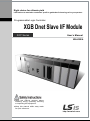
XGB Dnet Slave I/F Module
XGT Series
User’s Manual
XBL-DSEA
Read
this manual carefully before
installing, wiring, operating, servicing
or inspecting this equipment.
Keep
this manual within easy reach
for quick reference.
http://www.lsis.com
Safety Instruction
Before using the product …
For your safety and effective operation, please read the safety instructions thoroughly before using the
product.
► Safety Instructions should always be observed in order to prevent accident or risk with the safe and
proper use the product.
► Instructions are divided into “Warning” and “Caution”, and the meaning of the terms is as follows.
Warning
This symbol indicates the possibility of serious injury or death if some
applicable instruction is violated
Caution
This symbol indicates the possibility of severe or slight injury, and property
damages if some applicable instruction is violated
Moreover, even classified events under its caution category may develop into serious accidents relying
on situations. Therefore we strongly advise users to observe all precautions properly just like warnings.
► The marks displayed on the product and in the user’s manual have the following meanings.
Be careful! Danger may be expected.
Be careful! Electric shock may occur.
►
The user’s manual even after read shall be kept available and accessible to any user of
the product.
Safety Instruction
Safety Instructions for design process
Warning
Please install a protection circuit on the exterior of PLC so that the whole system may
operate safely regardless of failures from external power or PLC. Any abnormal output or
operation from PLC may cause serious problems to safety in whole system.
-
Install protection units on the exterior of PLC like an interlock circuit that deals with opposite
operations such as emergency stop, protection circuit, and forward/reverse rotation or install an
interlock circuit that deals with high/low limit under its position controls.
-
If any system error (watch-dog timer error, module installation error, etc.) is detected during
CPU operation in PLC, all output signals are designed to be turned off and stopped for safety.
However, there are cases when output signals remain active due to device failures in Relay
and TR which can’t be detected. Thus, you are recommended to install an addition circuit to
monitor the output status for those critical outputs which may cause significant problems.
Never overload more than rated current of output module nor allow to have a short circuit.
Over current for a long period time maycause a fire .
Never let the external power of the output circuit to be on earlier than PLC power, which may
cause accidents from abnormal output oroperation.
Please install interlock circuits in the sequence program for safe operations in the system
when exchange data with PLC or modify operation modes using a computer or other
external equipments Read specific instructions thoroughly when conducting control operations
with PLC.
Safety Instruction
Safety Instructions for design process
Caution
I/O signal or communication
line shall be wired at least 100mm away from a high-voltage
cable or power line. Fail to follow this
Safety Instructions on installation process
Caution
Use PLC only in the environment specified in PLC manual or general standard of data
sheet. If not, electric shock, fire, abnormal operation of the product may be caused.
Before install or remove the module, be sure PLC power is off. If not, electric shock or damage
on the product may be caused.
Be sure that every module is securely attached after adding a module or an extension
connector. If the product is installed loosely or incorrectly, abnormal operation, error or dropping
may be caused. In addition, contact failures under poor cable installation will be causing
malfunctions as well.
Be sure that screws get tighten securely under vibrating environments. Fail to do so will put
the product under direct vibrations which will cause electric shock, fire and abnormal operation.
Do not come in contact with conducting parts in each module, which may cause electric
shock, malfunctions or abnormal operation.
Safety Instruction
Safety Instructions for wiring process
Warning
Prior to wiring works, make sure that every power is turned off. If not, electric shock or
damage on the product may be caused.
After wiring process is done, make sure that terminal covers are installed properly
before its use. Fail to install the cover may cause electric shocks.
Caution
Check rated voltages and terminal arrangements in each product prior to its wiring
process. Applying incorrect voltages other than rated voltages and misarrangement among
terminals may cause fire or malfunctions.
Secure terminal screws tightly applying with specified torque. If the screws get loose, short
circuit, fire or abnormal operation may be caused. Securing screws too tightly will cause
damages to the module or malfunctions, short circuit, and dropping.
Be sure to earth to the ground using Class 3 wires for FG terminals which is exclusively
used for PLC. If the terminals not grounded correctly, abnormal operation or electric shock
may be caused.
Don’t let any foreign materials such as wiring waste inside the module while wiring,
which may cause fire, damage on the product or abnormal operation.
Make sure that pressed terminals get tighten following the specified torque. External
connector type shall be pressed or soldered using proper equipments.
Safety Instruction
Safety Instructions for test-operation and maintenance
Warning
Don’t touch the terminal when powered. Electric shock or abnormal operation may occur.
Prior to cleaning or tightening the terminal screws, let all the external power off including
PLC power. If not, electric shock or abnormal operation may occur.
Don’t let the battery recharged, disassembled, heated, short or soldered. Heat, explosion
or ignition may cause injuries or fire.
Caution
Do not make modifications or disassemble each module. Fire, electric shock or abnormal
operation may occur.
Prior to installing or disassembling the module, let all the external power off including
PLC power. If not, electric shock or abnormal operation may occur.
Keep any wireless equipment such as walkie-talkie or cell phones at least 30cm away
from PLC. If not, abnormal operation may be caused.
When making a modification on programs or using run to modify functions under PLC
operations, read and comprehend all contents in the manual fully. Mismanagement will
cause damages to products and accidents.
Avoid any physical impact to the battery and prevent it from dropping as well. Damages
to battery may cause leakage from its fluid. When battery was dropped or exposed under strong
impact, never reuse the battery again. Moreover skilled workers are needed when exchanging
batteries.
Safety Instruction
Safety Instructions for waste disposal
Caution
Product or battery waste shall be processed as industrial waste. The
toxic materials or explode itself.
waste may discharge
Revision History
Version
Date
Contents
Chapter
V 1.0
’15.3
First edition
-
※ The number of User’s manual is indicated right part of the back cover.
ⓒ 2015 LSIS Co., Ltd All Rights Reserved.
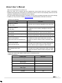
About User’s Manual
Thank you for purchasing PLC of LSIS Co.,Ltd.
Before use, make sure to carefully read and understand the User’s Manual about the functions, performances,
installation and programming of the product you purchased in order for correct use and importantly, let the end user and
maintenance administrator to be provided with the User’s Manual.
The User’s Manual describes the product. If necessary, you may refer to the following description and order accordingly.
In addition, you may connect our website (http://www.lsis.com/) and download the information as a PDF file.
Relevant User’s Manuals
Title
Description
XG5000 User’s Manual
(for XGK, XGB)
XG5000 User’s Manual
(for XGI, XGR)
XGK/XGB Instructions & Programming
User’s Manual
XGI/XGR/XEC Instructions & Programming
User’s Manual
XGK CPU User’s Manual
(XGK-CPUA/CPUE/CPUH/CPUS/CPUU)
XGI CPU User’s Manual
(XGI-CPUU/CPUH/CPUS)
XG5000 software user manual describing online function such as
programming, print, monitoring, debugging by using XGK, XGB
CPU
XG5000 software user manual describing online function such
as programming, print, monitoring, debugging by using XGI,
XGR CPU
User’s manual for programming to explain how to use
instructions that are used PLC system with XGK, XGB CPU.
User’s manual for programming to explain how to use
instructions that are used PLC system with XGI, XGR,XEC CPU.
XGK-CPUA/CPUE/CPUH/CPUS/CPUU user manual describing
about XGK CPU module, power module, base, IO module,
specification of extension cable and system configuration, EMC
standard
XGI-CPUU/CPUH/CPUS user manual describing about XGI
CPU module, power module, base, IO module, specification of
extension cable and system configuration, EMC standard
XGR- CPUH/F, CPUH/T user manual describing about XGR
CPU module, power module, extension drive, base, IO module,
specification of extension cable and system configuration, EMC
standard
XGR redundant series User’s
Manual
Current user manual of XBL-DSEA is written based on the following version.
Related OS version list
Product name
XBC H Type
OS version
V2.40
XBC SU Type
V1.50
XEC SU Type
V1.40
XEC H Type
V1.80
XBM Type
V3.50
XBC U Type
V1.10
XEC U Type
V1.10
XG5000
V4.0
1
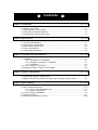
◎ Contents ◎
Chapter 1 Introduction……………………………………………………………………………… 1-1 ~ 1-4
1.1 What is DeviceNet…………………………………………………………………………
1.2 Characteristics of the Module ……………………………………………………………
1.3 Information for Module Operation …………………………………………………………
1.4 Configuration of Smart I/O for Dnet ………………………………………………………
1-1
1-2
1-3
1-4
Chapter 2 Specifications …………………………………………………………………………… 2-1 ~ 2-6
2.1
2.2
2.3
2.4
2.5
General Specifications ……………………………………………………………………
Performance Specifications ………………………………………………………………
Part names and Structure …………………………………………………………………
Cable Specifications ………………………………………………………………………
Terminating Resistances……………………………………………………………………
2-1
2-2
2-4
2-5
2-6
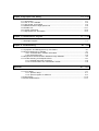
Chapter 3 Installation and Test Operation……………………………………………………… 3-1 ~ 3-8
3.1 Installation …………………………………………………………………………………… 3-1
3.1.1 Precautions for installation……………………………………………………… 3-1
3.1.2 Materials necessary for installation…………………………………………… 3-1
3.1.3 Installation………………………………………………………………………… 3-2
3.2 From Setting to Operation………………………………………………………… 3-7
3.3 Setting Procedure of SyCon and XG5000……………………………………………… 3-8
Chapter 4 System Configuration………………………………………………………………… 4-1 ~ 4-2
4.1 System with Dnet I/F module used ……………………………………………………… 4-1
4.2 System with Dnet I/F module and LSIS or other company’s slaves mixed…………… 4-2
Chapter 5 SyCon Settings………………………………………………………………………… 5-1 ~ 5-27
5.1 SyCon S/W Environment…………………………………………………………………… 5-1
5.1.1 SyCon S/W configuration file…………………………………………………… 5-1
5.1.2 System requirement……………………………………………………………… 5-1
5.2 SyCon Program Installations……………………………………………………………… 5-2
5.3 SyCon Execution…………………………………………………………………………… 5-7
5.4 Monitoring Information in SyCon………………………………………………………… 5-26
Chapter 6 High-speed Link Setting……………………………………………………………… 6-1 ~ 6-16
6.1
6.2
6.3
6.4
6.5
6.6
6.7
Introduction………………………………………………………………………………
How to use XG5000……………………………………………………………………
High-speed Link Editing…………………………………………………………………
Read and Write of High-speed Link……………………………………………………
Enable Link…………………………………………………………………………………
System Diagnosis………………………………………………………………………
High-speed Link Information……………………………………………………………
6-1
6-2
6-3
6-9
6-11
6-12
6-14
Chapter 7 Communication Program…………………………………………………………… 7-1 ~ 7-19
7.1 Example Program…………………………………………………………………………… 7-1
Chapter 8 Troubleshooting…………………………………………………………………………8-1 ~ 8-6
8.1 Symptoms and Management by LED Status…………………………………………… 8-1
8.2 System Diagnosis in XG5000……………………………………………………………… 8-1
8.2.1 Communication module information…………………………………………… 8-2
8.2.2 High-speed link…………………………………………………………………… 8-2
8.3 Diagnosis of Communication Module through XG5000………………………………… 8-4
8.4 Trouble shooting for Respective Error…………………………………………………… 8-5
8.4.1 XG5000 abnormal connection ………………………………………………… 8-5
8.4.2 Communication error with Master module……………………………………… 8-6
Appendix …………………………………………………………………………………………… A-1 ~ A-17
A.1 List of Flags ………………………………………………………………………………… A-1
A.1.1 Special relays …………………………………………………………………… A-1
A.1.2 Special register for data link …………………………………………………… A-9
A.2 Terminology………………………………………………………………………………… A-10
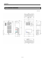
A.3 External Dimensions……………………………………………………………………… A-17
Chapter 1 Introduction
Chapter 1 Introduction
1.1 What is DeviceNet?
This user guide is made out to describe DevicsNet Slave I/F module (Referred to as “XBL-DSEA
Module”) among XGB PLC network modules. It is composed of Physical Layer and Data Link Layer
only. As of now, it is proposed as ISO 11898 and 11591-1 standards.
DeviceNet is an application layer developed by Rockwell / Allen-Bradley, it has been widely used in
the present industrial automation field.
Since DeviceNet uses CAN communication protocol, low-priced CAN micro chip applied will reduce
the cost. In addition, flexible counteractions against errors are also available by access to important
diagnosis information of device level which was impossible to use via the I/O interface.
.
1-1
Chapter 1 Introduction
1.2 Characteristics of the Module
DeviceNet (hereinafter referred to as Dnet) I/F module have features as follows;
▶ 1 master module can control 63 slave modules with the max. 28,000 points of I/O control
available.
▶ Multi-drop and T-diverged connection is available allowing the system to be extended and
changed easily with flexible system operation function provided.
▶ Open network available to connect with other company’s various slave modules.
▶ Master and slave can be set through Configuration Tool (SyCon), and communication control is
available through XG5000.
▶ Configuration Tool (XG5000)
1) Station number (MAC ID) can be specified (0 ~ 63) through Configuration Tool.
2) Communication speed can be specified (125/250/500 kbps) through Configuration Tool.
▶ Setup time and installation cost of the system will be saved from reduced connections and
wiring works by using a single cable for communication power(24V) and communication signal
line.
1-2
Chapter 1 Introduction
1.3 Information for Module Operation
1) It describes required components to operate the product.
Classification
Type
Description
Reference
Series
XBL-DSEA
DeviceNet I/F module.
Software for Station number, Speed,
Communication methods, configuration of
network setting.
Including module information (Product
code/Type, Maker name/Maker number)
- It is used to configure the network in SyCon.
Software for PLC programming
Slave
SyCon
Software
EDS
XG 5000
Setup for master
-
Remark
XG 5000 program can be downloaded at our company website. If you do not have an access to
the internet, contact the nearest agency for CD-ROM about XG 5000. EDS file related to our
slave module (Smart Link) can be downloaded at http://www.lsis.com
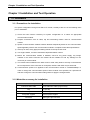
2) It describes about the number of module and position that can be installed in a single CPU module.
Dnet slave I / F module can be mounted up to two modules, regardless of main unit type.
Seven kinds of main units (XBC-U, XBC-H, XBC-SU, XEC-U, XEC-H, XEC-SU, XBM-S) can use
Dnet slave I / F module. Please consider the supported number of communication modules per
main unit when PLC sytem is organized. In addition, high-speed link function is only used and P2P
function is not used in XG5000.
Classification
Attachable
Number
High-speed link
number
Description
A maximum of 2
A maximum of 2
3) Please refer to below User Manuals to write communication program with Dnet I/F module.
• XGB Instruction Manual / XEC Instruction Manual
• XG 5000 User Manual
• LSIS Dnet master User Manual
• Other company’s User Manual which is related to Dnet master
• XGB Main Unit User Manual
1-3
Chapter 1 Introduction
1.4 Configuration of Smart I/O for Dnet
1) Dnet I/F modules of XGT series
Products
Details
Classification
Code
Designations
Master
47200005
XGL-DMEA
XGK Dnet Master I/F
Slave
47230166
XBL-DSEA
XGB Dnet Slave I/F
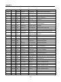
2) Slave Products List of Stand-alone type
Classification
Changeable
type
Product
Code
47060053
47060106
47060052
47060107
47060054
47060108
47060087
47060115
47060055
47060109
47060081
47060116
47060056
47060110
47060083
47060117
47060057
47060111
Designations
GDL-D22C
GDL-D22C(Q)
GDL-D24C
GDL-D24C(Q)
GDL-TR2C
GDL-TR2C(Q)
GDL-TR2C1
GDL-TR2C1(Q)
GDL-TR4C
GDL-TR4C(Q)
GDL-TR4C1
GDL-TR4C1(Q)
GDL-DT4C
GDL-DT4C(Q)
GDL-DT4C1
GDL-DT4C1(Q)
GDL-RY2C
GDL-RY2C(Q)
Details
DC input 16 points
DC input 16 points, Quick mode
DC input 32 points
DC input 32 points, Quick mode
TR output 16 points (0.5A, Source)
TR output 16 points (0.5A, Source), Quick mode
TR output 16 points (0.5A, Sink)
TR output 16 points (0.5A, Sink), Quick mode
TR output 32 points (0.5A, Source)
TR output 32 points (0.5A, Source), Quick mode
TR output 32 points (0.5A, Sink)
TR output 32 points (0.5A, Sink), Quick mode
DC input 16 points/TR output 16 points (0.5A,Source)
DC input 16 points/TR output 16 points (0.5A,Source), Quick mode
DC input 16 points/TR output 16 points (0.5A, Sink)
DC input 16 points/TR output 16 points (0.5A, Sink), Quick mode
Relay output 16 points
Relay output 16 points, Quick mode
3) Slave Products List of Extendable type
Classification
Communication
Adapter
Products
Code
47060131
Details
Designations
XDL-BSSA
Dnet I/F Adapter
Remark
1) Changeable type: C type of product whose I/O terminal block can be installed or removed.
2) Quick mode: Q type of product whose initializing time is 1.5 sec. after the communication power is On.
1-4
Chapter 2 Specifications
Chapter 2 Specifications
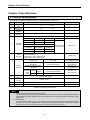
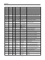
2.1 General Specifications
General specifications of XGB series are as specified below in Table 2.1.
No.
Item
Operating
temp.
Storage temp.
Operating
humidity
Storage
humidity
1
2
3
4
Specification
℃∼+55℃
0
-
℃∼+70℃
-25
5
Related specifications
-
5%RH, no dew allowed
∼9
∼95%RH, no dew
5
For discontinuous vibration
Frequency
Vibration
immunity
5
Impact
immunity
6
Noise
immunity
7
Acceleration
Amplitude
5≤f< 8.4 ㎐
-
3.5mm
8.4≤f≤150 ㎐
9.8 ㎨ (1G)
-
For continuous vibration
Frequency
Acceleration
Amplitude
5≤f< 8.4 ㎐
-
1.75mm
8.4≤f≤150 ㎐
4.9 ㎨ (0.5G)
-
Ambient
conditions
Operating
height
8
9
Number
Each 10 times in
X,Y,Z directions
* Max. impact acceleration: 147 ㎨ (15G)
* Authorized time: 11 ㎳
* Pulse wave : Sign half-wave pulse
(Each 3 times in X,Y,Z directions)
Square wave
AC: ±1,500V
impulse noise
DC: ±900V
Static electric
Voltage : 4kV
discharging
(contact discharging)
Radiation electromagnetic
80 ~ 1000MHz, 10 V/m
field noise
Fast
Transient Class
/burst
noise
Voltage
-
Power
module
Digital/Analog I/O
communication interface
2kV
1kV
IEC61131-2
IEC61131-2
Test specification of
LS Industrial Systems
IEC 61131-2,
IEC 61000-4-2
IEC 61131-2,
IEC 61000-4-3
IEC 61131-2,
IEC 61000-4-4
No corrosive gas or dust
2,000m or less
10
Pollution level
2 or less
11
Cooling type
Natural air cooling
Table 2.1 General Specifications
Notes
1)
2)
IEC (International Electrotechnical Commission):
An international nongovernmental organization which promotes internationally cooperated standardization
in electric/electronic field, publishes international standards and manages applicable estimation system
related with.
Pollution level:
An index indicating pollution level of the operating environment which decides insulation performance of
the devices. For instance, Pollution level 2 indicates the state generally that only non-conductive pollution
occurs. However, this state contains temporary conduction due to dew produced.
2-1
Chapter 2 Specifications
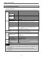
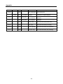
2.2 Performance Specifications
1) Performance specifications
Performance specifications of DeviceNet (hereinafter referred to as Dnet) I/F module are as described below.
Item
Transmission Speed (kbps)
Transmission Type
Communication Thick Cable
distance(m)
Thin Cable
Terminal resistance ()
125 kbps
Max.drop
250 kbps
length(m)
500 kbps
Data Packet
Message Access Control
125/250/500
Poll, Bit strobe, COS, Cyclic
500 (125kbps)/250 (250kbps)/100 (500kbps)
100 (125/250/500kbps)
121 (1%, 1/4W)
6 (Max. extended length 156)
6 (Max. extended length 78)
6 (Max. extended length 39)
0~8 Bytes
CSMA/NBA
Trunk/drop line
Power/Signal cable inside the identical network cable
Bus Type
Poll type
Transmission
Specification Network Structure
Max. number of nods
Up to 64 (including master) MAC IDs (MAC Identifier)
System Features
Operation Voltage
Insertion and removal of nod available in voltage On status
DC 24V
Module: Checks duplicated station/ Checks CRC error
SyCon: Detects defective station/Checks BusOff/Auto-scan
function
XG5000: Monitors High-speed link
Diagnosis Function
Master/Slave Operation
Parameter setting
Data process unit
XG5000
(Highspeed
link)
Performance Specifications
Available only in slave
1) Setting to High-speed link of XG5000
(RS-232C of CPU module or USB port)
Word
Select among 10ms, 20ms, 50ms, 100ms, 200ms, 500ms, 1s, 5s
Send/Receive period
and 10s
Max. communication point
Send 2048points, Receive 2048 points, 256 bytes respectively
Max. block number
64 (Setting range: 0~63)
- Default : 20ms
Max. point number per block
2048 points (256 bytes)
Max. modules installed
Up to 2
Internal-consumed current
Basic
Specification (mA)
Weight (g)
Module: 100mA, 5pin Connetor: 50mA
110g
Remark
1) Transmission distance of Dnet I/F module is inversely proportional to data transmission rate.
If thin cable is used, the transmission distance will be limited to 100m regardless of data
transmission rate.
2) CSMA/NBA (Carrier Sense Multiple Access with Non-destructive Bitwise Arbitration)
3) If the station No. of Dnet I/F module (master module) is specified, surely reset the applicable
slave module.
2-2
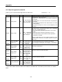
Chapter 2 Specifications
2) Communication methods
Communication methods can be set Poll, Bit-Strobe, COS(Change of State), Cyclic.
Communication method’s features are as shown below.
Communication
method
Poll
Bit-Strobe
Feature
Master and slave module Send/Receive the data by one on one.
It is used only in input module.
The way to transmit data simultaneously for master module from its input
type slave modules when the master module’s data transmission request
is received.
If input data status of slave module is changed, slave module transmits
changed data to master module. But output type slave module,
COS
(Change of State)
Settings Device Configuration Menu selection Connection Object
Instance Attributes Setting window Expected Packet Rate Category, transmits
every time according to its setting rates.
Slave module attempts to Send/Receive periodically.
Communication period setting, Settings
Cyclic
Device Configuration Menu
selection Connection Object Instance Attributes Setting window Expected
Packet Rate Category, sent/receives data periodically between master and
slave module according to its setting periods.
So, Communication method should be used with cautions along with data process of
Input/Output module in the system.
3) EDS (Electronic Data Sheet) file
▶ It is to allow other vendors to use restricted information of product through EDS file format.
Restricted information of product: Maker name and unique number (ODVA Certification)
Module information (Master and slave module)
Input/Output module information (Input point, Output point)
Information on communication support method
▶ EDS file addition: It can be executed by File Copy EDS.
Copied EDS file can be used only when located under EDS folder of SyCon execution directory
2-3
Chapter 2 Specifications
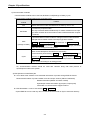
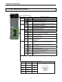
2.3 Part names and Structure
(1) LED display parts
LED
On
RUN
Off
Flickering
I/F
On
Off
On
HS
MS
Status
Normal
Error
Normal
LED display description
Completion of initializing.
Error is occurred.
Normal status of interface in Main unit.
Error
Error status of interface in Main unit .
Normal
Normal status of downloaded parameters from XG5000 and
High-speed link is normally enabled.
Flickering Error
I/O Connection is not accepted.
Off
Error
Abnormal status of downloaded parameters from XG5000 or
High-speed link is not enabled.
Off
Power Off
Power of main unit is off.
Green
Waiting
Flickering
Green
Normal
On
RED
Warning
Flickering
Critical
RED On
error
Green
/RED Initialization
Flickering
Off
Power Off
Green
Waiting
Flickering
NS
Green
On
Normal
Configuration is not complete or incorrect.
Normal communication status with Master.
Recoverable error status. (disconnected communication cable,
DC24V is not supplied)
unrecoverable error status
Initialization status
Offline status
- Non-completed status of checking duplicated MAC ID on
network.
- It is not supplied external power supply. (DC24V)
Communication waiting status with Master. (Stop
Communication)
Normal communication status with Master.
(Explicit Connection is on.)
Master module is separated network while communicating.
(Communication lines are short-circuited)
RED
Warning
Flickering
Network access failure
Critical
Red On
(Duplicated MAC ID, Bus-Off event)
error
Green
/RED Initialization Initialization status
Flickering
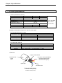
(2) 5pin connector (for external connection)
Color
Signal
Service
5 pin connector
Red
DC 24V(+)
Vcc
White
CAN_H
Bare
Drain
Blue
CAN_L
Signal
wire
Shielded
wire
Signal
wire
Black
DC 24V(-)
2-4
GND
121
Blue White
Black Bare Red
Chapter 2 Specifications
2.4 Cable Specifications
1) Cable specifications (Belden)
Classification
Thick (class1) Thick (class2)
Type
7897A
3082A
Cable Type
Round
Impedance (Ω)
120
Temperature range (℃)
-20 ~ 75
Max. allowable current(A)
8
Min. radius of curvature (in.)
4.4
4.6
Core wire number
5 wires
Thin (class2)
3084A
2.4
2.75
Trunk and Drop
line is used
concurrently
2) Maximum trasmission distance for repective cable types
(1) If one type of trunk line is used
Maximum distance
Transmission speed
Thick cable
500m
250m
100m
125kbps
250kbps
500kbps
Thin cable
100m
100m
100m
(2) If mixed with trunk line
Transmission speed
Max. distance if Thin and Thick cables are used as mixed
125kbps
Thick cable length + 5 x Thin cable length ≤ 500m
250kbps
Thick cable length + 2.5 x Thin cable length ≤ 250m
500kbps
Thick cable length + Thin cable length ≤ 100m
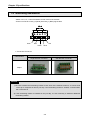
3) Structure
Copper-coated shield
Insulated coat
- Thick
- Thin
DC power cable (Red/Black)
- 15AWG 19X28 (Thick)
- 22AWG 19X34 (Thin)
Mylar Tape
Shielded cable
Signal cable (Blue/White)
- 18AWG 19X30 (Thick)
- 24AWG 19X36 (Thin)
2-5
Chapter 2 Specifications
2.5 Terminating Resistances
- Attach 121Ω, 1%, 1/4W of resistance to both ends of the network.
- Connect connector’s CAN_H (White) with CAN_L (Blue) signal cable.
121 Ω
Black
Red
Blue
Shield
White
• Connection Connector
Cable connection method
Classification
single direction connector
dual direction connector
Shape
Remark
1) Be sure to attach the terminating resistor to both ends of the network trunk line, or to both ends
of the tap if composed of device port tap. If the terminating resistor is omitted, communication
will not be normal.
2) If the terminating resistor is installed on the port tap, it is not necessary to install an additional
terminating resistor.
2-6
Chapter 3 Installation and Test Operation
Chapter 3 Installation and Test Operation
3.1 Installation
3.1.1 Precautions for installation
For system configuration through Dnet Slave I/F module, carefully make sure of the following items
prior to installation.
1) Check the basic factors necessary for system configuration so to select an appropriate
communication module.
2) Prepare accessories such as cable, tap and terminating resistor used for communication
module.
3) Speed of communication modules shall be identical respectively based on the communication
speed applicably used for the communication module in compliance with cable specifications.
4) If the tap is used, surely apply terminating resistor to the tap of both ends.
5) In a single network, it must be set without duplicated station number.
6) Before the communication module is installed, check for any power supply, any foreign
material on the base connector the module will be installed on and any damage on the
connector pin of the module.
7) The module when installed on the base board or used solely shall be securely connected with
the correspondent. If the connection is incomplete, interface with CPU may be abnormal.
8) Communication speed to be applied to this communication module is 125/250/500kbps. In
order to change the communication speed of slave module once specified, let it powered off
and then change the communication setting switch to apply the changed mode.
3.1.2 Materials necessary for installation
Materials necessary
Communication cable
Tap
Dnet I/F module
Thick cable/Thin cable (only for Dnet)
4,8-port tap
Terminating resistor
Terminating resistor : 121Ω, 1%, 1/4W
24V power supplier
General power supplier
Connector
Open type 5-pin connector
3-1
Chapter 3 Installation and Test Operation
3.1.3 Installation
1) Precautions for installation of the connector
Prior to installation of the connector, please pay attention to the following.
(1) Installation shall be performed when no signal and power supply is carried by cable.
(2) If the module installed on the system operates, stop the operation prior to installation.
After the installation is complete, secure the applicable cable tightly so to keep from being vibrated or
escaped.
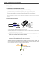
2) How to install the connector
5-pin
connecter
4cm
Red
White
Shield
Blue
Insulated round cable
7cm
Screw
Black
(1) First, slip off the coat of the cable about 7cm to connect.
(2) Cut the packing cover contracted about 4cm to cover on the cable and wrap up the exposed
conductor and insulated coat of the cable.
(3) Slip off the coat of the cable about 8mm at the both ends respectively and apply heat to the
packing cover contracted to adhere closely to the cable.
(4) Insert the slipped coat into the connector’s clamp screw with a proper distance and tighten
the screw (DC power supply and signal line is in identical cable, so ,be sure to make
designation of the signal identical between cable and connector).
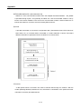
Tap-applied method and drop-applied method are available for the cable connection. And DC 24V
power is recommended to be installed on the position necessary to keep the voltage when lots of
Dnet I/F modules are expected or the cable is expected to get long.
Cable
Tap
Drop cable (Max. 6m)
(Thin cable)
Nod
3-2
Chapter 3 Installation and Test Operation
3) How to install the tap (8-port tap)
Connect to device port tap’s trunk line where up to 8 connections and disconnections are
available.
J1
J2
J3
J4
J5
J6
J7
J8
(1) The drop line composed of Thick or Thin cable can be connected with the device through the
tap. And if it is a Open-Style tap, 3 types of connectors can be used.
- Pluggable screw type
- Hard-wired screw type
- Soldered type
(2) The cable is most desirable to connect with drop line when the system does not
operate. If
the cable is to be connected when the system operates, check the connection status with
other devices and let it connected with the trunk line so to avoid the influence on
communication.
(3) When connected with the trunk line, don’t let the max. allowable length exceeded.
4) How to connect with network
(1) Max. network distance: stands for the distance between nodes most far away or between
terminating resistors.
Power
Max. network distance
Trunk
Trunk
Trunk
Node
Terminating
Resistor
Branch
Branch
Node
Node
Node
Branch line length
3-3
Trunk
Trunk
Terminating
Resistor
Chapter 3 Installation and Test Operation
(2) Branch line length: stands for the length (max. 6m) from the first branched position of the trunk
line to the last of the branch line.
Trunk
Trunk
Trunk
Trunk
4m
Branch line
(Max. 6m)
2m
1m
1m
Node
Node
Node
Node
2m
Node
(3) Communication distance compared with communication speed
Max. network length
Communication
speed
Thick
500kbps
100m or less
250kbps
250m or less
125kbps
500m or less
Branch line
Branch line
length
length in total
Thin
39m or less
100m or less
6m or less
78m or less
156m or less
5) Branch line length in total
- Distance of accumulated branch line length (length of each branch line shall be within the max. 6m)
Max. 3m from tap to communication power
Power
Trunk
Trunk
Trunk
Trunk
Trunk
Trunk
Terminating resistor
Terminating resistor
2m
6m
2m
1m
Node
3m
Node
Node
2m
1m
Node
2m
6m
Node
3-4
6m
Node
Node
Node
6m
Node
1m
Node
Node
2m
Chapter 3 Installation and Test Operation
As for the configuration example above, since the branch line length is within 6m, there is no problem
in the branch line length. However since the total length of the branch line is 40m which does not
comply with the max. branch line length of 39m with communication speed of 500kbps, 250 and
125kpbs are only available for communication.
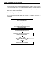
6) Network configuration and Checklist
Prior to the first network configuration, please check the system to be installed in the sequence as
specified below;
Consider characteristics of the system to configure.
(Select communication type)
Decide communication speed after due consideration of
response speed of the whole system.
Limit the length of trunk/branch/total branch line.
(Select Thick/Thin cable)
Decide communication speed, node arrangement,
communication cable standard and length.
Decide supply method of communication power.
(Consider power arrangement)
As specified
in DeviceNet standard?
Yes
Network configuration is completed.
3-5
No
Chapter 3 Installation and Test Operation
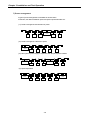
7) Power arrangement
4 types of power arrangement are available as shown below.
At this time, the distance between power and power tap shall be within 3m.
(1) If node is arranged in both directions of power
Communication
power
(2) If node is arranged in a direction of power
Communication
power
(3) If the system of power supply is separated, with the plural power installed
Communication
power
Communication
power
(4) If power duplicated
Communication
power
Communication
power
3-6
Chapter 3 Installation and Test Operation
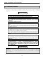
3.2 From Setting to Operation
The sequence of the product from installation to operation will be described below. After the product
installation is complete, install and configure the system to be operated as specified in the following
sequence.
Operation Sequence
Install Dnet Slave module.
Check the number of communication modules. (Max 2ea per main unit)
Configure the system with module.
Use DeviceNet cable specified, terminating resistor, tap, communication power to configure
the system.
Set the station number of slave module.
With power (master and slave module) On, check the LED status of the communication
module.
Check if the interface of the communication module is normal (I/F: Flickering, Run: On,
NMS: Green On) with CPU.
Execute SyCon
After Master is selected, Station number and Communication speed is specified then Auto
Scan function scan the configured information of network.
→ Check up the communication way of slave module whether the setting is correct and the
module which is different from system configuration is corrected then Auto Scan function is
operated.
Using XG5000
1) Execute [Read] 2) “High-speed link” 3) [Online]- [Communication module setting][Config.Upload (Dnet,Pnet) 4) Set the address of Read area/Save area for uploaded
slave module 5) [Online] – [Write] 6) [Online]–[Communication module setting][Enable Link].
XG5000
1) [Online]-[Connection] 2) [Online] – [Communication module setting] – [System
Diagnosis] 3) Select the Master module in System diagnosis window and Check the
system’s operation status at “High-speed link” and “Auto scan” (It appeared by right button
click of selected area).
Start Run
Remark
1) When the first station No. is initialized, the value read from the communication module will be kept
continuously. Thus, the details changed (station No., etc.) during communication will not be applied
during operation.
3-7
Chapter 3 Installation and Test Operation
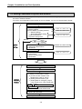
3.3 Setting Procedure of SyCon and XG5000
After setting the network configuration in SyCon software, then set the high speed link parameter
and data in XG5000 software.
If you don’t set configuration of the network in SyCon software, you can not communicate normally.
SyCon Execution
1. Master setting
1) Select Fieldbus
2) Insert Master (In editing window)
(1) Master Settings
- DeviceNet Master Setting
(2) Bus Parameters
(3) Device Assignment
Manual
SyCon
Setting
Automatic
2. Auto. Slave Setting
1) Automatic Network Scan
2) Download
XG5000 Execution
1) Reading information
Setting
Refer an item 5.3 4
Refer an item 5.3 5
Slave connection
2. Manu. Slave Setting(In editing window)
1) Insert Slave
2) Device Configuration
3) Download
XG5000
Refer an item 5.3 3
2) Setting the high speed link
(1) Setting communication module
a) Communication module: Dnet
- Module type, base no, slot no
b) Setting communication cycle
c) Setting data for emergency output
- CPU module error, CPU module stop
(2) Block setting
- Online Communication module setting
Config.Upload
-Address setting of Receive/Send area
3) Writing the parameter
4) Setting the Link Enable
3-8
Refer an item 5.3 5
Refer an item 5.3 6
Chapter 4 System Configuration
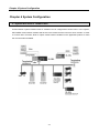
Chapter 4 System Configuration
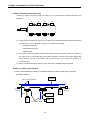
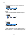
4.1 System with Dnet I/F module used
Communication system between Dnet I/F modules can be configured as shown below. In the system,
XGL-DMEA communication module shall be set to the master and the rest set to slave modules. In order
to connect with LS inverter, Dnet I/F option module shall be installed on the applicable product to make
the communication available.
4-1
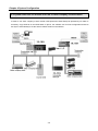
Chapter 4 System Configuration
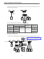
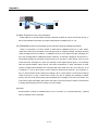
4.2 System with Dnet I/F module and LSIS or other company’s slaves mixed
In order to use other company’s slave module, EDS (Electronic Data Sheet) file provided by its maker is
necessary. Copy EDS file on the EDS folder of SyCon, the software tool for Dnet configuration and then
use SyCon automatically to set the slave modules existent in the network.
4-2
Chapter 5 SyCon Settings
Chapter 5 SyCon Settings
5.1 SyCon S/W Environment
5.1.1 SyCon S/W configuration file
5.1.2 System requirement
▪ Pentium 486 MHz above
▪ Windows 95/98/ME/NT/2000/XP
- Windows 95: Service Pack 1 above
- Windows NT: Service Pack 3 above
▪ 80Mbytes minimum free space
▪ CD ROM Drive required
▪ RAM memory minimum 16Mbytes required
▪ Graphic Resolution: 800 x 600 pixel minimum
▪ Windows 95: Service Pack 1 above
▪ Windows NT: Service Pack 3 above
5-1
Chapter 5 SyCon Settings
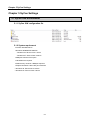
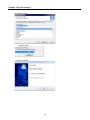
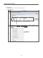
5.2 SyCon Program Installations
1) Executes ‘Autorun.exe’.
Select
‘System Installation’.
Selects ‘System Installation’.
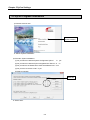
2) Executes ‘System Installation’.
(1) Do you want to install the System Configurator SyCon?
(2) Do you want to install the SyCon Integrated OPC Server?
yes
no
(3) Do you want to the Stand-Alone OPC Server/Busserver? no
(4) Do you have a License code? yes
(5) Select Language.
Select here
Select ‘Next’.
5-2
Chapter 5 SyCon Settings
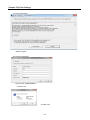
3) License Agreement
Select ‘I agree’.
4) Program Registration
License Code: F90BF4B3E874
Select ‘OK’.
Select ‘Yes’.
5-3
Chapter 5 SyCon Settings
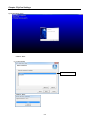
5) Configuration setup
Select ‘Next’.
(1) Components
Select the network to install.
Select ‘Next’.
5-4
Chapter 5 SyCon Settings
(2) Program Folder
Select ‘Next’.
(3) Setup complete
5-5
Chapter 5 SyCon Settings
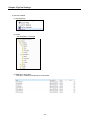
6) Content installed
(1) Execution file
(2) Folder
- File destination: C:\Program Files\LS Industrial Systems\SyCon
(3) EDS file for DeviceNet
EDS file is created automatically as shown below.
5-6
Chapter 5 SyCon Settings
5.3 SyCon Execution
Set the basic parameter for Dnet communication between master and slave. Master and slave
configuration has 2 methods as shown below.
(1) Configuration with EDS file
Advantages: It can be set the slave which is not connected actually.
Disadvantages: If setting is wrong, the communication is operated abnormally.
(2) Auto Scan
Advantages: It can be set the parameter easily and speedy.
Disadvantages: It can be set only connected slave.
So, Use the methods properly by situation.
1) Initial screen execution
Menu bar
Icon bar
[Network]
Menu bar
Icon bar
[Editing screen]
5-7
Status bar
Chapter 5 SyCon Settings
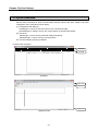
2) Configuration menu
Main menu
File
Editor
Submenu
Description
New
Make New File.
M/S
Open
Open existed File.
M/S
Close
Close activated file.
M/S
Save
Save activated file.
M/S
Save As
Save activated file as another name.
M/S
Export
Export Project file.
M/S
Copy
DBM Copy DBM extension file.
M/S
CSV Copy CSV extension file.
M/S
Print…
Print.
M/S
Print Preview
Preview print.
M/S
Print Setup…
Print setup.
M/S
Recent File
Display file list recently used.
M/S
Exit
Exit SyCon.
M/S
Cut
Cut.
S
Copy
Copy.
S
Paste
Paste.
S
Delete
Delete.
S
Replace
Replace.
Device Table
Address Table
View
Remark
Display of Network setting status.
(MAC ID, Master/Slave)
Display Input/Output size and slave module
address.
Logical Network
Change into initial Logical Network View from
View
editing screen.
Toolbars
M/S
M/S
M/S
M/S
Standard To activate standard menu bar.
M/S
Fieldbus To activate Insert Icon menu bar.
M/S
Status Bar
To display Status Bar in basic SyCon screen.
M/S
Master
It selects to insert master module.
M/S
Device
It selects to insert slave module.
M/S
Insert
* Remark
M: It means Master. It activates when master is selected in editing screen.
S: It means Slave. It activates when slave is selected in editing screen.
5-8
Chapter 5 SyCon Settings
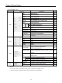
Main menu
Submenu
Description
Download
To download SyCon setting file.
M
Start Debug Mode
It displays present connection status.
M
Device Diagnostic
It displays saved diagnostic information.
M
Firmware Download
It is used for downloading Firmware.
M
Firmware/Reset
Reset Firmware.
M
Extended Device Diagnostic Extended diagnostic function of Device.
Global State Field
I/O Monitor
To display I/O data.
M
Message Monitor
Data analysis between Master and Slave
M
Automatic Network Scan
Set Network automatically.
M
Change of slave attribute.
S
Start Communication
Start communication.
M
Stop Communication
Stop communication.
M
Device Info
Display of Device’s manufacture data
and Serial number.
M
Activate Driver
Register unregistered device.
M
Read project Information
Display Project information.
M
Device Assignment
Bus Parameters
Master Settings
Help
M
M
Set Device Attribute
Window
and module status.
M
status per station number.
Get Device Attribute/
Settings
It displays present communication status
It displays module’s information and
Live List
Online
Remark
Set the method to communicate with
Host.
It is used for setting of communication
M
speed and parameter.
M
Master module setting.
M
Device Settings
-
-
Device Configuration
Set Slave parameter.
S
Auto Addressing
Assign the address automatically.
M/S
Project Information
Project information.
M/S
Path
GSD setting file and project path.
M/S
Language
Select language.
M/S
Cascade
Window array is Cascade mode.
M/S
Tile
Window array is Tile mode.
M/S
Help Topics
View Help Topics.
M/S
About
SyCon program information.
M/S
* Remark
M: It means Master. It activates when Master is selected in editing screen.
S: It means Slave. It activates when Slave is selected in editing screen.
5-9
Chapter 5 SyCon Settings
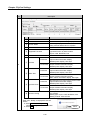
3) New File
Master must be set by New file, It can be set the slave automatically in Auto-scan.
Classification
Configuration screen
Fieldbus
Screen
Configuration
Select Master
Master type
XGT
XGL-DMEA
5-10
EDS File Name
Master name
COMCDNM
COM-C-DNM
Chapter 5 SyCon Settings
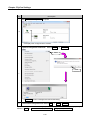
4) Master/Slave selection
(1) Master
A) Selection
Method
Selection sequence
Insert
Menu bar
→
Master
Icon
B) Insertion
Classification
DeviceNet
Master
Insertion
Master
Selection
Master type
XGT
XGL-DMEA
EDS File Name
Master name
COMCDNM
COM-C-DNM
C) Editing
After editing
Master editing
Previous editing
5-11
Chapter 5 SyCon Settings
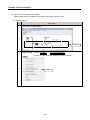
(2) Slave
It can be executed after master is inserted.
A) Selection
Method
Menu bar
Selection Sequence
→
Insert
Execution Icon
Slave
Icon
B) Insertion
Slave selection
Slave Insertion
DeviceNet
PLC
Slave type
DC input 16 point
DC input 32 point
DC input 16point,
Tr output 16 point
Relay output 16 point
Tr output 16 point
Tr output 32 point
Extendable Smart IO
XGB Dnet Slave I/F
Inverter
EDS File Name
Slave name
GDL-D22A
GDL-D22A/D22C
GDL-D24A
GDL-D24A/D24C
GDL-DT4A
GDL-DT4A/DT4A1/DT4B/DT4C/D54C1
GDL-RY2A
GDL-TR2A
GDL-TR4A
XDL-BSSA
XBL-DSEA
IS5V2_1
GDL-RY2A/RY2C
GDL-TR2A/TR2A1/TR2B/TR2C/TR2C1
GDL- TR4A/TR4A1/TR4B/TR4C/TR4C1
XDL-BSSA
XBL-DSEA
IS5
C) Editing
After editing
Slave editing
Previous editing
5-12
Chapter 5 SyCon Settings
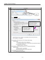
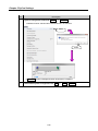
5) Master setting
To set Master, Master must be selected in editing screen.
(1) Setting sequence
Step
Description
Master selection in editing screen
1
Selected
Master
Master Setting:
Settings
Master Settings
Select
2
5-13
Chapter 5 SyCon Settings
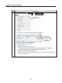
Step
Description
1) To change or set MAC ID and Master name
After
settings
Then
Select
2) Select Settings
DeviceNet Master Setting
[초기설정]
[설정변경]
3
☞ Select ‘Buffered, host controlled’ in ‘Handshake of the process data’ from
‘No consistence, uncontrolled’
(1) Parameter to user interface: Do not change default setting.
Default setting:
A) Start behavior after system Initialization.
Controlled release of the communication by the application program
B) User program monitoring.
Watch dog time : 1000 (ms)
(2) Parameter to process data interface: Do not change default setting.
Default setting:
A) Address Mode : Byte address
B) Storage Format (Word Module): Big Endian
(3) Handshake of the process data
- Select ‘Buffered, host controlled’
5-14
Chapter 5 SyCon Settings
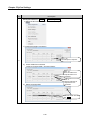
Step
Description
Bus parameter setting:
Settings
Bus Parameters
Select
▶ To change Communication Speed and MAC ID Master
4
After setting
and then select
‘OK’
Baudrate: Among 125, 250, 500 KBits/s
1) MAC ID Master: Among 0 ~ 63
2) Auto clear mode
(1) When Auto clear mode is selected
If the error is occurred in slave module, All communication is stopped.
Dnet I/F module’s HS LED flickering, MNS LED Red ON
(2) When Auto clear mode is not selected
If the error is occurred in slave module, the communication of normal slave
module is continued.
5-15
Chapter 5 SyCon Settings
Step
Description
Serial port selection: Settings Device Assignment
Select the disconnected Port in COM Port of computer.
1) Initial screen before connection
Error: -20
No COM port in computer.
5
2) Check COM Port connection
Check ‘Connect COM 1, Connect COM 4’
Error: -51
There is COM Port in
computer but it is not
connected.
Error: 0
There is COM Port in
computer and it is
connected.
3) Select connected Port
Select the check box and
click OK
5-16
Chapter 5 SyCon Settings
Step
Description
Automatic Network setting: Online Automatic Network Scan
Configured slave system information is automatically scanned.
Select
1) Initial screen before Scan
6
2) Screen after Scan
If scan is finished, ‘Ready’ is displayed in
Then
Current Status.
Then, Select Automatic Configuration.
5-17
Select OK
Chapter 5 SyCon Settings
Step
Description
It displays configured Slave information in Network.
①
②
③
⑤
④
No.
⑦
⑥
⑧
Item
⑩
⑨
Description
① MAC ID Master: 0
Master station number display
② Baudrate: 125KBits/s
Communication speed setting display
③ Current Status
Processing display
Ready: Automatic Network Scan is completed
④ Address: MAC ID 0 ~ MAC ID 63
Max. connectible station with network
⑤ Supported Functions
Communication configuration which is
supported function by slave module
- Cyclic, COS, Bit-Strobe, Poll
⑥ Device Name
Connected slave Device name
Produced
⑦ Poll Size
6
- Data transmission from master module to slave module
Consumed - Output module information display
- Module points display, Unit: Byte
Produced
⑧ BitStr. Size
- Data transmission from slave module to master module
- Input module information display
- Module points display, Unit: Byte
- Data transmission from master module to slave module
Consumed - Output module information display
- Max. station information display, Unit: Byte
Produced
⑨ Cyc/COS. Size
- Data transmission from slave module to master module
- Input module information display
- Module points display, Unit: Byte
- Data transmission from slave module to master module
- Input module information display
- Module points display, Unit: Byte
- Data transmission from master module to slave module
Consumed - Output module information display
- Module points display, Unit: Byte
User specifies the communication method of
slave module.
- Setting type: Cyclic, COS, Bit-Strobe, Poll
- Setting method: Click the Cell
⑩ Choosen Config
After scan, ‘Ready’ is displayed at Current
Status.
Select Automatic Configuration,
Check the using of scanned information.
Select OK.
5-18
Select
Chapter 5 SyCon Settings
Step
Description
After Automatic Configuration completed
6
It displays the configured slave module.
System configuration download:
Select Online
Download
Select
Select
7
Download window is disappeared after downloading.
8
Save edited configuration file: Select File
Save or Save As
If the above 8 phases is finished, High-speed link setting is available after [Config.Upload] at
XG5000. (Online Communication module setting Config.Upload(Dnet, Pnet)
5-19
Chapter 5 SyCon Settings
6) Slave module setting (Manual setting)
Slave module setting is available on the editor. Select slave module to edit.
(1) Setting sequence
Step
Description
Select Slave in editor window
1
Select slave
Slave setting:
1) Select Settings
Device Configuration
2) Select the slave in editor window and Click the mouse
2
Select
5-20
Chapter 5 SyCon Settings
Step
Description
Editing of Slave setting parameter
①
⑧
③
②
⑤
④
⑥
⑦
No.
Item
①
MAC ID & Description
②
Actual chosen IO
connection
③
Actual device
④
Connection Object
Instance Attributes
⑤
Parameter Data
⑥
Available predefined
connection data types
⑦
Configured
I/O Connection data
and offset address
⑧
OK
3
Description
- Slave station number setting: 0~63
- Slave description setting (in English)
- Activate device in actual configuration
1) If it is selected: It is existed in network.
2) If it is not selected: It is not existed in network.
- Communication method which slave module supports:
Cyclic, COS, Bit-Strobe, Poll
- UCMM Check: It is applicable to slave module which
supports the function.
It displays the configured slave in network.
-Expected packet rate:
1) COS: Reception period of output module.
2) Cyclic: Transmission/Reception period of input/output
module.
-Production Inhibit Time: Delayed time between the data
(Transmission or reception data)
-Watchdog Timeout Action: No response from slave module.
1) Transition to timeout: Maintenance of error status.
2) Auto delete: It makes to delete in network automatically.
3) Auto reset: It makes to recover automatically.
-Fragmented Timeout: Maximum response time when data is
transmitted to slave module (more
than 8 byte)
-Produced connection size: Slave input data size
-Consumed connection size: Slave output data size
Module parameter data in EDS file
Data type: Standard data type
Description: Input or output data display
Data length: Data length
Data type: Standard data type
Description: Module name
I Type: Standard input data type
I Len: Input data length
I Address: Input data start address
O Type: Standard output data type
O Len: Output data length
O Address: Output data start start address
Save the configured data value
5-21
Chapter 5 SyCon Settings
Step
Description
System configuration download: Online
Download
Master must be selected when Download menu is executed.
Select
Select
4
Download window is disappeard when download is completed.
5
Save edited system configuration file: File
5-22
Save or Save As
Chapter 5 SyCon Settings
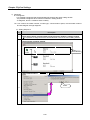
7) Diagnosis
▶ To diagnose
- It is possible to diagnose that the downloaded file exists at the same editing window.
- It is possible to diagnose when master is selected in editing window.
- To diagnose, above 2 conditions have to satisfy.
▶ It can confirm the station number, module type, communication speed, communication method
and wire diagram through diagnosis.
(1) Setting Sequence
Step
1
Description
Open the file which is downloaded in Dnet I/F master module in editing window
It is possible to diagnose that the downloaded file exists at the same editing window.
Select master in editing window
Select Master
2
Start communication:
Online
Start Communication
Select
3
5-23
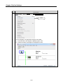
Chapter 5 SyCon Settings
Step
Description
Debug Mode : Select Online
Start Debug Mode
Select
4
The wire diagram is changed after debug mode started.
1) If normal status, wire diagram is displayed green color.
2) If abnormal status, wire diagram is displayed red color.
5-24
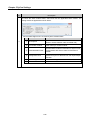
Chapter 5 SyCon Settings
Step
Description
To check the slave module status, select and click the applicable slave module. The
setting window is appeared as shown below.
①
②
③
④
⑤
⑥
Device status flags menu is checked by slave module status.
No.
Item
Description
4
① No response
Specified slave module is not existed in network.
(Solution: Check Network cable and Baud rate)
② Error buffer overflow
Error data’s information is overflowed the limited
buffer memory in master module.
③ Parameterization fault
Specified slave module’s information in SyCon is not
correspondent with slave module’s information in
network.
④ Configuration fault
Input/Output data size of slave module which is
specified in SyCon is different from real Input/Output
data size.
⑤ UCMM support
Slave module supports the UCMM.
⑥ Deactivated
Slave module status is abnormal.
5-25
Chapter 5 SyCon Settings
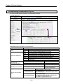
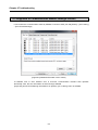
5.4 Monitoring Information in SyCon
It monitors variable status information of communicating network.
1) Global State Field
Menu
Sequence
Description
Online
Global State Field…
Select
Global State Field’s description is as shown below.
Classification
Online master main
state
Collective status bits
Collective online error
location and
corresponding error
Description
OPERATE Master module is operating.
STOP
Communication part of Master module is not operation.
PDUP
Device executes the duplicated MAC ID checking.
DMAC
Duplicated MAC ID module is existed.
NRDY
The communication of main program is not ready.
EVE
Transmission error
FAT
Communication can not available because of fatal error.
NEXC
The at least 1 device can not reach Data Exchange State.
ACLR
All devices stop the communication and are cleared
automatically.
CTRL
Master parameter error
Error at remote address
Error address displayed
corresponding error event
Counter of detected bus off report
Error event displayed
Counting the number of Bus
off
Statistic bus information Counter of rejected telegram transmissions Counting the rejected
telegram transmissions
Parameterized Devices Display of parameterized slave module (Blue)
Display of activating slave module
(Yellowish green)
Activated Devices
-The yellowish green is disappeared when slave
Device specific status
module has the error.
bits
Display of activating slave module (Red)
Devices with Diagnostic -The diagnosis window is appeared when red
color station is double-clicked.
Refer to 7) Diagnosis’s 4 step.
5-26
Chapter 5 SyCon Settings
2) Live List
Menu
Sequence
Description
Online
Live List
Be activated
Be inactivated
Devices: It displays slave station number.
1) Activation: It displays normal communicating slave module.
Select 2) Inactivation: It displays abnormal communicating slave module.
5-27
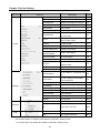
Chapter 6 High-speed Link Setting
Chapter 6 High-speed Link Setting
6.1 Introduction
High-speed link specifies the Send/Receive device area and data size between CPU module and the
communication module by XG5000.
High-speed link can be set the function as shown below.
Description
Communication
module setting
Communication
period setting
(Period type)
High-speed Link
Module type
Base no.
Dnet
Base number is only set 0.
Select among 10ms, 20ms, 50ms, 100ms, 200ms, 500ms, 1s, 5s, 10s.
- Default setting: 20 ms
Latch
Keep the previous output status.
Output data setup CPU error Clear
Clear the output.
in case of
Latch
Keep the previous output status.
emergency
CPU stop
Clear
Clear the output.
Communication
Send
:
the
data
transfer
from master module to slave module
module
note1
Mode
Receive : the data transfer from slave module to master module
setting
note1
Station No.
Slave station number (Range: 0 ~ 63)
Communication
The communication method between master and slave(Poll, Bit-Strobe, COS, Cyclic)
note1
Method
Address
Head address of the sending device
Read area
(From Master to Sizenote1
Input/Output point of slave module is displayed Byte.
Slave module) (Byte)
- If input /Output module is less than 8 bit, it is processed 1 Byte.
Address
Head address of the receiving device
Save area
(From Slave to Sizenote1
Input/Output point of slave module is displayed in Byte.
Master module) (Byte)
- If input/Output module is less than 8 bit, it is dealt with 1 Byte.
PLC connection
RS-232C or USB Port of CPU module
Control condition
It can control regardless of position of Run mode switch (Run, Stop) of CPU module.
Max. communication point
Send 2048points, Receive 2048 points, 256 bytes respectively
Max. block number
64 (Setting Range : 0~63)
Max. point per block
1024 points (64 Words)
Number of High-speed link
Up to 2
setting
Note
Note1 : It must be set equal to the slave setting of ‘Configuration Tool’.
▶ When High-speed link is edited, parameter has to download again.
▶ High-speed link is used per a communication module.
▶ CPU module saves the written parameter (Standard, High-speed link, P2P).
▶ When CPU module is exchanged, parameter in XG5000 has to back-up and then the parameter has to
write in CPU module again.
6-1
Chapter 6 High-speed Link Setting
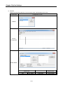
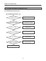
6.2 How to use XG5000
XG5000 usage for Dnet I/F module is as shown below.
XG5000 execution
1) Read I/O information
Read Dnet I/F module information
2) Station number, Communication
speed setting.
a) Station number: 0~63
b) Communication speed: 125kbps,
250kbps, 500kbps
or
3) High-speed link setting
(1) Communication module setting
a) Communication module setting:
Dnet
- Module type, Base, Slot
b) Communication period setting
c) Data setup in case of emergency
-CPU module error, CPU module stop
(2) Block setting
- Online SyCon Upload
- Read area/Save area address
setting
1) Connects High-speed link and Dnet I/F module.
2) PLC’s program synchronizes with slave module’s
input/output point setting in SyCon. It is to
synchronize the using device and address.
Write of High-speed link parameter value of installed
Dnet I/F module.
4) Write Parameter
or
5) Enable Link
Communication permission of installed Dnet I/F
module.
or
6-2
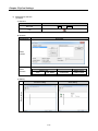
Chapter 6 High-speed Link Setting
6.3 High-speed Link Editing
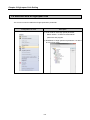
XG5000 is executed as shown below.
[Standard window]
The parameter in XG5000 is as shown below.
Basic setting
High-speed link
P2P
[Parameter window]
Dnet I/F module is set in High-speed link window. It can use the High-speed link up to maximum 2.
A High-speed link is available per a Dnet I/F module.
6-3
Chapter 6 High-speed Link Setting
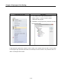
How to use High-speed link window
Parameter is specified at High-speed link window as shown below. There are 2 kinds of
parameter setting, Communication module setting and High-speed link block setting.
High-speed link
Parameter setting
Communication module setting
Select
and
Click
High-speed link block setting
Select
and
Click
Remark
High-speed link1 [B0S1 XBL-DSEA] is as shown below.
1) High-speed link 01: It is a serial number of High-speed link.
2) B0: It means Base number.
3) S0: It means Slot number. (Example: Slot number 1 – S1, Slot number 3 – S3)
6-4
Chapter 6 High-speed Link Setting
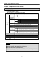
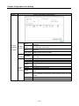
1) Communication module setting parameter
Communication module parameter setting is as shown below.
Parameter
Setting item
Description
Module type Dnet
Communi- Base Nonote1.
cation
note1
module
Slot No
setting
High-speed
Setting range: 0
Setting range: 1 ~ 10
It is different from type of main unit.
Setting range: 1 ~ 2
(in case of XBCU, XECU: 1~3)
XGB can use 2 of High-speed link.
link index
Select among the 10ms, 20ms, 50ms,
100ms, 200ms, 500ms, 1s, 5s, 10s.
Communication period
- Default: 20ms
setting
- It is only for transmission data.
(Period type)
- Received data is processed every end of
program.
Keep the output status.
CPU Latch (But, P device’s data is cleared.)
error
Clear Clear all of the output.
Output
Keep the output status.
data setup CPU Latch (But, P device’s data is cleared.)
in case of stop
Clear Clear all of the output.
emergency
Keep the output status.
Comm Latch (But, P device’s data is cleared.)
error
Clear Clear all of the output.
Remark
Note1: It can be set just once when high-speed link is created.
Cautions of communication period setting
1) Setting value of communication period is applicable to transmission data (CPU module’s data
Dnet I/F module). If communication period is longer than the time of changing data at scan
program, It might be different from the data which is transmitted to slave module.
6-5
Chapter 6 High-speed Link Setting
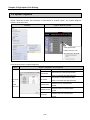
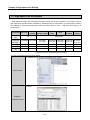
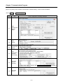
2) Parameter of High-speed link block setting
High-speed link block setting parameter is as shown below.
(1) High-speed link editing window.
Classification
High-speed link block setting window
Block
editing
Each entry of speed link setting windows is as follows.
Classification Contents
Index
Read area
Read area
Word size
Save area
Save area
Word size
Number of high-speed link block
Starting address of the device to be transmitted from the slave module to the master
module.
Indicate the size of a send data
Starting address of the device to be received by the master module.
Indicate the size of a receive data
6-6
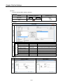
Chapter 6 High-speed Link Setting
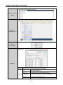
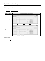
(2) High-speed link block editing
Head address of Send/Receive address can be edited in High-speed block.
Select index to edit and please set Read area & Save area.
Classification
Description
Screen
After
If you complete setting
about Read area and Save
area, the color of character
will be changed from red to
black.
uploaded
the data
Classification
Station type
Block type
High-
*1
*1
*1
Station No.
speed link Block No. *1
Read area
block
(Master module
editing
Slave
module)
window
Save area
(Slave module
Master module)
Description
Select slave.
Transmission: Data is transmitted from master module to slave module.
Reception: Data is transmitted from slave module to master module.
Slave station number (range: 0 ~ 63)
Not used in Dnet I/F module.
Address Head address of transmitting device.
*1
Size
(Byte)
Input/Output point of slave module is displayed in Word.
- If input module point is less than 8 bit, it is dealt with 1 Byte.
Address Head address of receiving device.
*1
Size
(Byte)
Input/Output point of slave module is displayed in Word.
- If input module point is less than 8 bit, it is dealt with 1 Byte.
The priority order of data is the slave module which has lowest index number.
Remark
Less than 8 point module is processed by 1 Word when address is specified.
6-7
Chapter 6 High-speed Link Setting
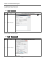
(3) How to use High-speed link block editing tool
The editing tool and usage of High-speed link block is as shown below.
Screen 1: Right
mouse (right click)
button of a selected
area
[Screen 1]
Undo
Undo edited index block.
Redo
Redo edited index block.
Cut
Cut the edited index block.
Copy
Copy the edited index block.
Paste
Paste the copied index block.
Delete
Delete the edited index block.
Display by Tree structure.
View
Tree by
Transmission/
Reception
6-8
Chapter 6 High-speed Link Setting
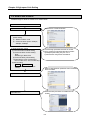
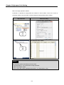
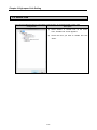
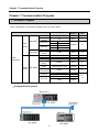
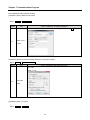
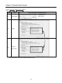
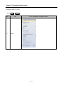
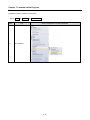
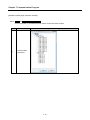
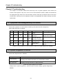
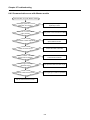
6.4 Read and Write of High-speed Link
The screen is used for read/write of High-speed link’s parameter.
Configuration of menu
Description
1) It can read for each High-speed parameter.
Select “Online” “Read” to read network
-
parameter and program.
2) Read/Write of High-speed link parameter not affect
to CPU’s Run mode.
6-9
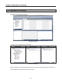
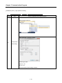
Chapter 6 High-speed Link Setting
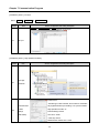
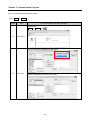
Configuration of menu
Description
1) It can read for each High-speed parameter.
Select “Online” “Write” to Write network
-
parameter and program.
2)
Read/Write of High-speed link parameter not affect
to CPU’s Run mode.
If High-speed link parameter is written to CPU module, CPU module saves the data. If CPU module
is exchanged, High-speed link parameter has to backup from CPU module. The parameter has to rewrite in exchanged CPU module.
6-10
Chapter 6 High-speed Link Setting
6.5 Enable Link
You need to enable the link for actual data communication of the downloaded HS link data.
Configuration
Description
1) Select “Online” “Enable Link” on the menu.
Then, “Enable Link” screen appears.
2) Check the item you want to enable and click
“Write”.
6-11
Chapter 6 High-speed Link Setting
6.6 System Diagnosis
System diagnosis provides the information of Dnet Slave I/F module system. The System diagnosis
screen is as shown below.
Menubar
System diagnosis window
Click right mouse
button, then you can
see the menu as below.
It describes the menu of system diagnosis.
Menu
Screen configuration and description
Module Kind
Base number
Communic-
Slot number
Communication module type.
Base number of communication module
which is connected with High-speed link.
Slot number of communication module
which is connected with High-speed link.
ation
module
Hardware Error
Hardware error of communication
module.
information
Hardware version
OS Version
6-12
Hardware version of communication
module.
Software version of communication
module.
Chapter 6 High-speed Link Setting
Menu
Screen configuration and description
Base number of communication module which is connected with Highspeed link.
HS (HighCommunication Display communication setting among the communication methods
Standard method
(Poll, Bit-Strobe, Cyclic, COS).
speed) link
information
Slot number of communication module which is connected with HighSlot no.
information
speed link.
Master station Station number of Dnet I/F module.
Status of link enable. (Enable: 1. Disable: 0)
Total HS Run link
link
Error: Error is occurred in slave station after Run link becomes normal
Link trouble
information
status.
Index
Arrange starting from the lowest station number in SyCon.
Block number
Block number of High-speed link
Block type
Block type of High-speed link
Data size of transmitting/receiving data from master module to slave
Data size
module.
Read area
Read device area for transmitting
Individual
Save area
Save device area for receiving
HS link
Display of error occurring Transmission/Reception status or Error
information HS state
status.
RUN: Normal communication status between master and slave module.
HS mode
STOP: Abnormal communication status between master and slave
module.
HS trx
Display of communication status between master and slave module.
HS error
Error is displayed while High-speed link data is processed.
Base no.
6-13
Chapter 6 High-speed Link Setting
6.7 High-speed Link Information
High-speed link swaps the data between master module and all slave modules. It provides the flag of
High-speed link operation status classified by individual station or total station. It is useful when checking
the reliability of Transmission/Reception data and finding cause of error. Flag kinds and usage is as
shown below.
Classification Run-Link
LinkTrouble
Transmission/ Operation
Reception status
mode
Information
All
type
Flag name
(x=High-speed _HSxRLINK _HSxLTRBL
link number)
Data type
Bit
Bit
Monitoring Available
Available
Program
Available Availability
use
Error
High-speed
link status
Block
setting
Respectively
_HSxTRX[n]
(n=0..63)
Bit Array
Availability
Availability
_HSxSET
_HSxMOD[n] _HSxERR[n] _HSxSTATE
BLOCK[n]
(n=0..63)
(n=0..63) [n] (n=0..63)
(n=0..63)
Bit Array
Bit Array
Bit Array
Bit Array
Availability Availability Availability Availability
Availability
Availability
Availability
[Table] Function of High-speed link information
The way of selecting flag is as shown below.
1-1 XG5000 Edit Tools Normally Open contact
Select Contact
1-2 Flags
Register in
Variable/Comment
6-14
Availability
Chapter 6 High-speed Link Setting
1-3 Use flag by Normally Open Contact
Use flag in ladder
program
2-1 XG-5000 Monitor window Right Click Register in Variable/Comment
Register in
Variable/Comment
Select
PLC, Program
Select Flags
Select flag
Flag type
Select list
Select among the System/High-speed link/P2P/PID.
List
Select High-speed link
All
It is showed the list of all High-speed links.
Parameter
It means High-speed link number. The selected
number
number is only displayed in List.
Block index
It is index number of High-speed link block.
6-15
Chapter 6 High-speed Link Setting
Monitoring of flag and device’s value is as shown below.
Flag monitor
- Select variable in Variable/Comment screen and then Drag/Drop the variable to
Variable Monitoring Window. The value is appeared in variable Monitoring Window.
6-16
Chapter 7 Communication Program
Chapter 7 Communication Program
7.1 Example Program
Basic configuration of example and setting value is as shown below.
Classification
1
Setting
program
XG5000
Setting
phase
5-3
Poll
SyCon
5-1
XG5000
6-1
2
SyCon
4-3
COS
SyCon
5-3
0
0
0
XG5000
XG5000
SyCon
5-1
5-1
1-5, 3-1
125kbps
SyCon
3-1
High-speed link 2 area
XG5000
5-1
200ms
XG5000
5-1
M000
2Word
M010
XG5000
XG5000
XG5000
1Word
XG5000
Description
Station No.
Communication
method
XBL-DSEA
Slave
Module
System
configuration
Device
Size
Device
Size
Read area
Save area
Station No.
XDL-BSSA
Communication
(DO 16Point)
method
Base No.
Slot No.
Station No.
Communication
Speed
High-speed link
setting
Master
XGL-DMEA
Communication
Module
period setting
Read area
Save area
• Configuration of system
7-1
M100
1Word
M110
1Word
6-1
7-1
Chapter 7 Communication Program
XBL-DSEA(Dnet Slave Module) Setting
[ XG5000 1 phase ] Make a new project
Menu : Project New Project
Phase
Item
Screen configuration and setting description
After typing Project name, select CPU series, CPU type. And then click OK
1-1
Make a new
project
[ XG5000 2 phase] Connection setting between PC with CPU module
Menu : Online Connection setting
phase
Item
Screen configuration and setting description
Tye: USB
Depth : Local
2-1
Connection
setting
[ XG5000 3 phase ] Connect
Menu : Online Connect
7-2
Chapter 7 Communication Program
[ XG5000 4 phase ] I/O Sync
Menu : Online Diagnosis I/O Information
Phase
Item
Screen configuration and setting description
Online Change Mode Stop and then do I/O Sync
4-1
I/O Sync
[ XG5000 5 phase ] High-speed link setting
Phase
5-1
Item
Screen configuration and setting description
Project window Add Item High-speed Link Communication
Add Highspeed link
Initial screen
- Module type, base number, slot number is automatic
5-2
Communication
ally registered when proceeding I / O synchronization.
module
High-speed link index: 01
settings
Period settings: 20ms
(XBL-DSEA)
CPU error: Clear
CPU stop: Clear
Network with master error: Clear
7-3
Chapter 7 Communication Program
Communication
module
5-3
settings
(XBL-DSEA)
Station Number : 1
Network Speed : 125kbps
[ XG5000 6 phase ] Read area/Save area setting
Phase
Item
Screen configuration and setting description
Select send, receive mode
Communication
6-1
module setting
High-speed link block after Read area/Save area setting
[ XG5000 7 phase ] Write Network parameter
Menu : Online Write
Phase
Item
Screen configuration and setting description
Initial screen
7-1
Write
parameter
Written parameter is saved CPU module
- If CPU module is exchanged, High-speed link parameter has to backup from used CPU
module
[XG5000 8 phase ] High-speed link enabling
Menu : Online Communication module setting Enable Link (HS Link, P2P)
7-4
Chapter 7 Communication Program
[SyCon 1 phase] Master and MAC ID setting
Menu: File New
Phase
1-1
Item
Screen configuration and setting description
Make a new file
- Make a new file.
1-2
Select fieldbus
- Select DeviceNet.
Master setting
Insert Master or
1-3
Master setting
Master type
: COM-C-DNM
1-4
Select masters
MAC ID: 0
1-5
Description: Master
MAC ID setting
(Input only English and figure)
1-6
Master setting
completion
7-5
Chapter 7 Communication Program
[SyCon 2 phase] Change of Basic setting
Menu: Settings Master Settings
Phase
Item
Screen configuration and setting description
Master MAC ID: 0
2-1
Master Settings
2-2
Settings
2-3
Name: Master
Change of
setting value
*Only ‘Handshake of the process data’ setting can be set.
7-6
Chapter 7 Communication Program
[SyCon 3 Phase] Baudrate
Menu: Settings Bus Parameter
Phase
Item
Screen configuration and setting description
Baudrate: 125KBits/s
3-1
Bus
MAC ID Master: 0
Parameter
Auto clear mode: Refer to 5-3-4.
* Auto clear mode
(1) If Auto clear mode is selected
If error is occurred in slave module, the communication stops for the whole system.
Dnet I/F module’s HS LED is flickering, MNS LED red light flickering.
(2) If Auto clear mode is not selected
If error is occurred in slave module, the communication keeps for normal slave module.
7-7
Chapter 7 Communication Program
[SyCon 4 phase] Slave and MAC ID setting
Menu: Insert Master
Phase
Item
Screen configuration and setting description
Master setting
Insert Master
4-1
or
Slave setting
1 phase: Device filter (Classified by product maker)
4-2
Select slave
2 phase: Available Devices (Select slave module)
7-8
Chapter 7 Communication Program
Phase
Item
Screen configuration and setting description
MAC ID (Slave module MAC ID setting)
4-3
MAC ID setting
Description: Device1/ Device2/ Device3
4-4
Slave setting
completion
7-9
Chapter 7 Communication Program
[SyCon 5-1 phase] Slave module communication methods setting – Slave module: XBL-DSEA
Menu: Settings Device Configuration
Phase
Item
Screen configuration and setting description
Slave module setting
5-1
Slave
communicati
on methods
setting
5-2
Slave
MAC ID
Communication method: Poll
5-3
Slave
communicati
on method
Transmission/Reception data period and response condition setting
Poll is default communication method.
5-4
Slave
Transmissio
n/
Reception
period
setting
MAC ID setting: 1
Information of EDS File (Data type, Input/Output characteristic, Data length).
5-5
Slave data
structure
(EDS File)
Select ‘BYTE ARRAY’ and then click Append to configured I/O data. The data is
displayed as next 5-6 phase.
Slave structure (Data type, Input/Output characteristic, Data length) is transmitted to
master module.
5-6
Slave data
structure
7-10
Chapter 7 Communication Program
[SyCon 5-2 phase] Slave module communication methods setting – Slave module: XDL-BSSA
Menu: Settings Device Configuration
Phase
Item
Screen configuration and setting description
Slave module setting
5-1
Slave
communication
methods
setting
5-2
Slave
MAC ID
5-3
Slave
Communication method: COS
communication
method
5-4
Slave
Transmission/
Reception
period setting
MAC ID setting: 2
Transmission/Reception data period and response condition setting
Poll is default communication method.
In case of COS: Expected packet rate : 200(ms) setting
(Expected packet rate > Production Inhibit time)
Information of EDS File (Data type, Input/Output characteristic, Data length).
5-5
Slave data
structure
(EDS File)
Select ‘BYTE ARRAY’ and then click Append to configured I/O data. The data is
displayed as next 5-6 phase.
Slave structure (Data type, Input/Output characteristic, Data length) is transmitted to
master module.
5-6
Slave data
structure
7-11
Chapter 7 Communication Program
[SyCon 6 phase] Serial port selection
The cable diagram is same as RS-232C cable diagram using in CPU module. Use same kind cable.
Menu: Settings Device Assignment
Phase
Item
Screen configuration and setting description
Serial port
6-1
Serial port
setting
Connect COM1 Connect COM2 Connect COM3 Connect COM4
Activated port’s error value displayed ‘0’.
6-2
Port search
Check COM 1 (
) and Select OK.
[SyCon 7 phase]
Menu: Online Download
7-12
Chapter 7 Communication Program
XGL-DMEA(Dnet Master Module) Setting
[ XG5000 1 phase ] Make a new project
Menu: Project New Project
phase
Item
Screen configuration and setting description
After typing Project name, select CPU series, CPU type. And then click OK
1-1
Make a new project
[XG5000 2 phase ] Connection settings
Menu: Online Connection settings
phase
2-1
Item
Screen configuration and setting description
Connection settings
Connection settings: USB
Depth : Local
7-13
Chapter 7 Communication Program
[ XG5000 3 phase ] Connect
Menu: Online Connect
phase
3-1
Item
Screen configuration and setting description
Connect
7-14
Chapter 7 Communication Program
[ XG5000 4 phase ] Read I/O Information
Menu: Online Diagnosis I/O Information
phase
4-1
Item
Screen configuration and setting description
I/O Information
7-15
Chapter 7 Communication Program
[ XG5000 5 phase ] High-speed link setting
Menu : View High-speed link Add Item High-speed link communication
phase
Item
Screen configuration and setting description
Make a High-speed link
High-speed link 2: Dnet I/F module
5-1
Communication
module setting
Module type: Dnet
Base no.: 00
Slot no.: 00
Communication period settings: 200ms
7-16
Chapter 7 Communication Program
[ XG5000 6 phase ] SyCon Upload
Menu: Online Communication module setting Config.upload (Dnet, Pnet)
phase
Item
Screen configuration and setting description
Select index
Communica
6-1
tion module
settings
SyCon Upload
[ XG5000 7 phase ] Read area/Save area setting
phase
Item
Screen configuration and setting description
Initial screen
Communicatio
7-1
n
module
setting
Read area/Save area after setting High-speed link block
(XGL-DMEA)
7-17
Chapter 7 Communication Program
[ XG5000 8 phase ] Write High-speed link parameter
Menu : Online Write
phase
Item
Screen configuration and setting description
Select High-speed link and then write
Write
8-1
Parameter
Parameter is downloaded after click ‘OK’.
Written parameter is saved CPU module.
- If CPU module is exchanged, High-speed link parameter has to backup from used CPU
module.
7-18
Chapter 7 Communication Program
[XG5000 9 phase] High-speed link enabling
Menu: Online Enable Link (HS Link, P2P)
Communication is permitted between master module and slave module.
phase
9-1
Item
Screen configuration and setting description
Communication
is permitted
7-19
Chapter 8 Troubleshooting
Chapter 8 Troubleshooting
This chapter is to describe various errors that may occur in system operation, their causes and
actions to take against. If any error occurs on the communications module, related error details will
be displayed through LED of the communication module. Follow the procedures below to shoot the
troubles after checking for errors displayed, based on the applicable LED status referring to product
specification.
8.1 Symptoms and Management by LED Status
It shows the symptoms of communication module by LED status and the management.
(When High-speed link is enabled)
RUN
I/F
HS
D-RUN
MNS
Green
ON
Red
ON
ON
Flickering
OFF
Flickering
ON
Flickering
ON
ON
ON
Flickering
Flickering
Flickering
Green
ON
ON
Flickering
Flickering
Flickering
Red
ON
OFF
OFF
OFF
-
-
Symptoms
High-speed link
disable
Slave connection
abnormal
SyCon setting
changed while Highspeed link is executed
Whole slave
connection error
Critical defect
Management
Slave connection check
Check slave setting
Check slave connection
Check slave setting
Ask customer service
center
[Table 8.1] The symptoms of communication module error (High-speed link is enabled)
8.2 System Diagnosis in XG5000
It shows the diagnosis item in XG5000.
Diagnosis item
Communication
module information
High-speed link
Description
It displays the standard information of communication module.
It displays the flag information of High-speed link.
[Table 8.2] System diagnosis in XG5000
It diagnoses the system by [Online] – [Communication module setting] – [System Diagnosis] in
XG5000.
8-1
Chapter 8 Troubleshooting
8.2.1 Communication module information
It displays the information of Dnet I/F module.
[Figure 8.1] Communication module information
8.2.2 High-speed link
[Figure 8.2] High-speed link
8-2
Chapter 8 Troubleshooting
High-speed link diagnosis
Classification
Classification
(Main item)
(Sub item)
Description
Base no.
Base number of attached module
Standard
Slot no.
Slot number of attached module
information
Master station
Master station number
Communication method
Slave’s communication method
Normal: All station is a normal communication.
Total High-speed
Run link
Error: If only one station can not to communicate,
it is an error.
link information
Individual High-
Link trouble
Communication line’s status
Index
High-speed link parameter index
Block number
High-speed link block number
Block type
Show the type of transmission
Data size
Transmission/Reception data size (Byte)
Read area
Head of read area
Save area
Head of save area
HS state
Present HS state
HS mode
Present operation state
HS trx
Transmission/reception state
HS error
Error state
speed link
information
[Table 8.3] High-speed link diagnosis
8-3
Chapter 8 Troubleshooting
8.3 Diagnosis of Communication Module through XG5000
It can monitor the communication status by XG5000. Connect to CPU port and [Online] – [PLC History]
– [PLC Errors/Warnings].
[Figure 8.5] Detailed information of PLC history
If hardware error or CPU interface error is occurred, communication module’s LED operates
abnormally. Also, the error information is shown through XG5000.
[Figure 8.5] shows Error/Warning information from [Online] - [PLC History] menu in XG5000.
8-4
Chapter 8 Troubleshooting
8.4 Trouble shooting for Respective Error
8.4.1 XG5000 abnormal connection
XG-5000 abnormal connection
Communication serial port
set correct?
No
Correct the serial cable’s port
applicable to communication module.
Yes
Close another program’s serial port.
Try again SyCon connection.
Yes
Another program using
the communication serial port?
No
Powered normally?
No
Supply the power.
Yes
CPU module abnormally?
No
Check CPU module status.
Yes
Serial cable problem?
No
Check serial cable.
Yes
Operating environment proper
general specification?
No
Operate the communication module
Proper environment.
Yes
Ask to customer service center.
8-5
Chapter 8 Troubleshooting
8.4.2 Communication error with Master module
Communication error with Master module
High-speed link’s
parameter set correctly?
No
Correct High-speed link’s parameters
applicably to slave.
Yes
Any errors in communication
supply module?
Yes
Check power of communication modules.
No
Slave station number duplicated?
Yes
Correct slave and
SyCon station number.
No
Cable connection error?
Yes
Correct the cable connection
No
Terminal resistor connected
to both ends of network?
No
Connect terminal resistor (121 Ω)
to both ends of network.
Yes
Cable length exceeding
specified range?
Yes
Use specified cable and cable length.
No
Network cable used as mixed?
Yes
Use single type of cable as specified.
No
Ask to customer service center.
8-6
Appendix
A.1 List of Flags
A.1.1 Special relays
Device 1
Device 2
F0000
Type
Variable
DWORD _SYS_STATE
Function
Description
Mode & Status
PLC mode & run status displayed.
F00000
BIT
_RUN
RUN
RUN status.
F00001
BIT
_STOP
STOP
STOP status.
F00002
BIT
_ERROR
ERROR
ERROR status.
F00003
BIT
_DEBUG
DEBUG
DEBUG status.
F00004
BIT
_LOCAL_CON
Local control
Local control mode.
Modbus mode
Modbus control mode.
Remote mode
Remote control mode.
_MODBUS_CO
N
_REMOTE_CO
N
F00005
BIT
F00006
BIT
F00008
BIT
_RUN_EDIT_ST
F00009
BIT
_RUN_EDIT_C
HK
F0000A
BIT
_RUN_EDIT_D
ONE
F0000B
BIT
_RUN_EDIT_E
ND
F0000C
BIT
_CMOD_KEY
F0000D
BIT
_CMOD_LPADT Run Mode
Run Mode changed by local PADT.
F0000E
BIT
_CMOD_RPAD
T
Run Mode changed by remote PADT.
F0000F
BIT
_CMOD_RLINK Run Mode
F00010
BIT
_FORCE_IN
Compulsory input Compulsory input status.
F00011
BIT
_FORCE_OUT
Compulsory
output
Compulsory output status.
F00012
BIT
_SKIP_ON
I/O SKIP
I/O SKIP being executed.
F00013
BIT
_EMASK_ON
Error mask
Error mask being executed.
F00014
BIT
_MON_ON
Monitor
Monitor being executed.
F00015
BIT
_USTOP_ON
STOP
Stopped by STOP function
F00016
BIT
_ESTOP_ON
ESTOP
Stopped by ESTOP function.
F00017
BIT
_CONPILE_MO
Compiling
DE
Compile being performed.
F00018
BIT
_INIT_RUN
Initializing
Initialization task being performed.
F0001C
BIT
_PB1
Program code 1
Program code 1 selected.
F0001D
BIT
_PB2
Program code 2
Program code 2 selected.
F0001E
BIT
_CB1
Compile code 1
Compile code 1 selected.
F0001F
BIT
_CB2
Compile code 2
Compile code 2 selected.
Modification
during run
Modification
during run
Modification
complete during
run
Modification
complete during
run
Run Mode
Run Mode
A-1
Program being downloaded during run.
Modification in progress during run.
Modification complete during run.
Modification complete during run.
Run Mode changed by key.
Run Mode changed by remote communication
module.
Appendix
Device 1
Device 2
Type
Variable
DWORD _CNF_ER
F0002
Function
Description
System error
Serious error in system reported.
F00020
BIT
_CPU_ER
CPU error
CPU configuration error found.
F00021
BIT
_IO_TYER
Module type error
Module type is not identical.
F00022
BIT
_IO_DEER90
Module installation
Module is displaced.
error
F00023
BIT
_FUSE_ER
Fuse error
Fuse blown.
F00024
BIT
_IO_RWER
Module I/O error
Module I/O error found.
F00025
BIT
_IP_IFER
F00026
BIT
_ANNUM_ER
Module interface
error
External
equipment Error
Error found in Special/communication
module interface.
Serious error detected in external
equipment.
F00028
BIT
_BPRM_ER
Basic parameter
Basic parameter is abnormal.
F00029
BIT
_IOPRM_ER
IO configuration parameter abnormal.
F0002A
BIT
_SPPRM_ER
Special module parameter abnormal.
F0002B
BIT
_CPPRM_ER
IO parameter
Special module
parameter
Communication
module parameter
F0002C
BIT
_PGM_ER
Program error
Program error found.
F0002D
BIT
_CODE_ER
Code error
Program code error found.
F0002E
BIT
_SWDT_ER
System watch-dog System watch-dog active.
F0002F
BIT
_BASE_POWER_
Power error
ER
Base power abnormal.
F00030
BIT
_WDT_ER
Scan watch-dog
Scan watch-dog active.
System warning
Slight error in system reported.
DWORD _CNF_WAR
F0004
Communication
abnormal.
module
F00040
BIT
_RTC_ER
RTC error
RTC data abnormal.
F00041
BIT
_DBCK_ER
Back-up error
Data back-up error found.
F00042
BIT
_HBCK_ER
Restart error
Hot restart unavailable.
F00043
BIT
_ABSD_ER
Run error stop
Stopped due to abnormal run.
F00044
BIT
_TASK_ER
Task impact
Task being impacted.
F00045
BIT
_BAT_ER
Battery status abnormal.
F00046
BIT
_ANNUM_WAR
Battery error
External
equipment error
F00047
BIT
_LOG_FULL
Memory full
Log memory full
F00048
BIT
_HS_WAR1
HS link 1
HS link – parameter 1 error
F00049
BIT
_HS_WAR2
HS link 2
HS link – parameter 2 error
F0004A
BIT
_HS_WAR3
HS link 3
HS link – parameter 3 error
F0004B
BIT
_HS_WAR4
HS link 4
HS link – parameter 4 error
F0004C
BIT
_HS_WAR5
HS link 5
HS link – parameter 5 error
F0004D
BIT
_HS_WAR6
HS link 6
HS link – parameter 6 error
F0004E
BIT
_HS_WAR7
HS link 7
HS link – parameter 7 error
F0004F
BIT
_HS_WAR8
HS link 8
HS link – parameter 8 error
F00050
BIT
_HS_WAR9
HS link 9
HS link – parameter 9 error
A-2
parameter
Slight error detected in external equipment.
Appendix
Device 1
Device 2
Type
F00051
BIT
_HS_WAR10
HS link 10
HS link – parameter 10 error
F00052
BIT
_HS_WAR11
HS link 11
HS link - parameter11 error
F00053
BIT
_HS_WAR12
HS link 12
HS link - parameter12 error
F00054
BIT
_P2P_WAR1
P2P parameter 1
P2P - parameter1 error
F00055
BIT
_P2P_WAR2
P2P parameter 2
P2P – parameter2 error
F00056
BIT
_P2P_WAR3
P2P parameter 3
P2P – parameter3 error
F00057
BIT
_P2P_WAR4
P2P parameter 4
P2P – parameter4 error
F00058
BIT
_P2P_WAR5
P2P parameter 5
P2P – parameter5 error
F00059
BIT
_P2P_WAR6
P2P parameter 6
P2P – parameter6 error
F0005A
BIT
_P2P_WAR7
P2P parameter 7
P2P – parameter7 error
F0005B
BIT
_P2P_WAR8
P2P parameter 8
P2P – parameter8 error
F0005C
BIT
_CONSTANT_ER
Fixed cycle error
Fixed cycle error
_USER_F
User contact point Timer available for user.
F0009
WORD
Variable
Function
Description
F00090
BIT
_T20MS
20ms
CLOCK of 20ms cycle.
F00091
BIT
_T100MS
100ms
CLOCK of 100ms cycle.
F00092
BIT
_T200MS
200ms
CLOCK of 200ms cycle.
F00093
BIT
_T1S
1s
CLOCK of 1s cycle.
F00094
BIT
_T2S
2s
CLOCK of 2s cycle.
F00095
BIT
_T10S
10s
CLOCK of 10s cycle.
F00096
BIT
_T20S
20s
CLOCK of 20s cycle.
F00097
BIT
_T60S
60s
CLOCK of 60s cycle.
F00099
BIT
_ON
Always ON
Bit always ON.
F0009A
BIT
_OFF
Always OFF
Bit always OFF
F0009B
BIT
_1ON
1 scan ON
Bit only ON for the first scan.
F0009C
BIT
_1OFF
1 scan OFF
Bit only OFF for the first scan.
F0009D
BIT
_STOG
Reverse
Every scan reversed.
_USER_CLK
User CLOCK
CLOCK available to set by user.
F0010
WORD
F00100
BIT
_USR_CLK0
F00101
BIT
_USR_CLK1
F00102
BIT
_USR_CLK2
F00103
BIT
_USR_CLK3
F00104
BIT
_USR_CLK4
F00105
BIT
_USR_CLK5
F00106
BIT
_USR_CLK6
F00107
BIT
_USR_CLK7
Repeat specific
scan
Repeat specific
scan
Repeat specific
scan
Repeat specific
scan
Repeat specific
scan
Repeat specific
scan
Repeat specific
scan
Repeat specific
scan
A-3
ON/OFF CLOCK 0 for specific scan
ON/OFF CLOCK 1 for specific scan
ON/OFF CLOCK 2 for specific scan
ON/OFF CLOCK 3 for specific scan
ON/OFF CLOCK 4 for specific scan
ON/OFF CLOCK 5 for specific scan
ON/OFF CLOCK 6 for specific scan
ON/OFF CLOCK 7 for specific scan
Appendix
Device 1
Device 2
F0011
Type
WORD
Variable
Function
Description
_LOGIC_RESULT Logic result
Logic result displayed.
F00110
BIT
_LER
Calculation error
ON for 1 scan if calculation in error.
F00111
BIT
_ZERO
Zero flag
ON if calculation result is 0.
F00112
BIT
_CARRY
Carry flag
ON if Carry found during calculation.
F00113
BIT
_ALL_OFF
Whole output OFF
ON if all output OFF
_LER_LATCH
Calculation error
latch
ON kept if calculation in error.
_CMP_RESULT
Compared result
Compared result displayed.
F00115
F0012
BIT
WORD
F00120
BIT
_LT
LT flag
ON if “less than”
F00121
BIT
_LTE
LTE flag
ON if “less than or equal”
F00122
BIT
_EQU
EQU flag
ON if “equal”
F00123
BIT
_GT
GT flag
ON if “greater than”
F00124
BIT
_GTE
GTE flag
ON if “greater than or equal”
F00125
BIT
_NEQ
NEQ flag
ON if “not equal”
F0013
WORD
_AC_F_CNT
Inspected power cut
Number of inspected power-cuts
displayed.
F0014
WORD
_FALS_NUM
FALS No.
FALS No. displayed.
F0015
WORD
_PUTGET_ERR0 PUT/GET error 0
Main base PUT / GET error
F0016
WORD
_PUTGET_ERR1 PUT/GET error 1
Added base step 1 PUT / GET error
F0017
WORD
_PUTGET_ERR2 PUT/GET error 2
Added base step 2 PUT / GET error
F0018
WORD
_PUTGET_ERR3 PUT/GET error 3
Added base step 3 PUT / GET error
F0019
WORD
_PUTGET_ERR4 PUT/GET error 4
Added base step 4 PUT / GET error
F0020
WORD
_PUTGET_ERR5 PUT/GET error 5
Added base step 5 PUT / GET error
F0021
WORD
_PUTGET_ERR6 PUT/GET error 6
Added base step 6 PUT / GET error
F0022
WORD
_PUTGET_ERR7 PUT/GET error 7
Added base step 7 PUT / GET error
F0023
WORD
_PUTGET_NDR0 PUT/GET complete 0
Main base PUT / GET complete
F0024
WORD
_PUTGET_NDR1 PUT/GET complete 1
Added base step 1 PUT / GET complete
F0025
WORD
_PUTGET_NDR2 PUT/GET complete 2
Added base step 2 PUT / GET complete
F0026
WORD
_PUTGET_NDR3 PUT/GET complete 3
Added base step 3 PUT / GET complete
F0027
WORD
_PUTGET_NDR4 PUT/GET complete 4
Added base step 4 PUT / GET complete
F0028
WORD
_PUTGET_NDR5 PUT/GET complete 5
Added base step 5 PUT / GET complete
F0029
WORD
_PUTGET_NDR6 PUT/GET complete 6
Added base step 6 PUT / GET complete
F0030
WORD
_PUTGET_NDR7 PUT/GET complete 7
Added base step 7 PUT / GET complete
F0044
WORD
_CPU_TYPE
CPU type
Information on CPU type displayed.
F0045
WORD
_CPU_VER
CPU version
CPU version displayed.
F0046
DWORD _OS_VER
OS version
OS version displayed.
F0048
DWORD _OS_DATE
OS date
OS released date displayed.
A-4
Appendix
Device 1
Device 2
Type
Variable
Function
Description
F0050
WORD
_SCAN_MAX
Max. scan time
Max. scan time displayed
F0051
WORD
_SCAN_MIN
Min. scan time
Min. scan time displayed
F0052
WORD
_SCAN_CUR
Present scan time Present scan time displayed.
F0053
WORD
_MON_YEAR
Month / Year
PLC’s time information (Month/Year)
F0054
WORD
_TIME_DAY
Hour / Date
PLC’s time information (Hour/Date)
F0055
WORD
_SEC_MIN
Second / Minute
PLC’s time information (Second/Minute)
F0056
WORD
_HUND_WK
100 years / Day
PLC’s time information (100 years/Day)
F0057
WORD
_FPU_INFO
FPU calculation
result
Floating decimal calculation result
displayed.
F00570
BIT
_FPU_LFLAG_I
Incorrect error latch Latched if in incorrect error.
F00571
BIT
_FPU_LFLAG_U
Underflow latch
Latched if underflow found.
F00572
BIT
_FPU_LFLAG_O
Overflow latch
Latched if overflow found.
F00573
BIT
_FPU_LFLAG_Z
Latch divided by 0 Latched if divided by 0.
F00574
BIT
_FPU_LFLAG_V
Invalid calculation
Latched if invalid calculation.
latch
F0057A
BIT
_FPU_FLAG_I
Incorrect error
Reported if incorrect error found.
F0057B
BIT
_FPU_FLAG_U
Underflow
Reported if underflow found.
F0057C
BIT
_FPU_FLAG_O
Overflow
Reported if overflow found.
F0057D
BIT
_FPU_FLAG_Z
Division by 0
Reported if divided by 0.
F0057E
BIT
_FPU_FLAG_V
Invalid calculation Reported if calculation invalid.
F0057F
BIT
_FPU_FLAG_E
Irregular value input Reported if irregular value input.
F0058
DWORD _ERR_STEP
Error step
Error step saved.
F0060
DWORD _REF_COUNT
Refresh
Increased when module refresh executed.
F0062
DWORD _REF_OK_CNT
Refresh OK
Increased if module refresh normal
F0064
DWORD _REF_NG_CNT
Refresh NG
Increased if module refresh abnormal.
F0066
DWORD _REF_LIM_CNT
Refresh LIMIT
Increased if module refresh abnormal
(TIME OUT).
F0068
DWORD _REF_ERR_CNT
Refresh ERROR
Increased if module refresh abnormal.
F0070
DWORD
_MOD_RD_ERR_
CNT
_MOD_WR_ERR_
DWORD
CNT
Module READ
ERROR
Module WRITE
ERROR
Increased if module reads 1 word
abnormally.
Increased if module writes 1 word
abnormally.
F0074
DWORD _CA_CNT
Block service
Increased if module’s block data serviced
F0076
DWORD _CA_LIM_CNT
F0078
DWORD _CA_ERR_CNT
Block service
LIMIT
Block service
ERROR
Increased if module’s block data service
abnormal.
Increased if module’s block data service
abnormal.
F0080
DWORD _BUF_FULL_CNT Buffer FULL
Increased if CPU’s internal buffer is FULL.
F0082
DWORD _PUT_CNT
PUT count
Increased if PUT executed.
F0084
DWORD _GET_CNT
GET count
Increased if GET executed.
F0086
DWORD _KEY
Present key
Local key’s present status displayed.
F0088
DWORD _KEY_PREV
Previous key
Local key’s previous status displayed.
F0072
A-5
Appendix
Device 1
Device 2
Type
Variable
Function
Description
Slot number with discordant module type
displayed.
Slot number with displaced module
displayed.
F0090
WORD
_IO_TYER_N
Discordant slot
F0091
WORD
_IO_DEER_N
Displaced slot
F0092
WORD
_FUSE_ER_N
Fuse blown slot
F0093
WORD
_IO_RWER_N
F0094
WORD
_IP_IFER_N
F0096
WORD
_IO_TYER0
Slot number with fuse blown displayed.
Slot number with module Read/Write
RW error slot
error displayed.
Slot number with module interface error
IF error slot
displayed.
Module type 0 error Main base module type error.
F0097
WORD
_IO_TYER1
Module type 1 error Added base step 1 module type error.
F0098
WORD
_IO_TYER2
Module type 2 error Added base step 2 module type error.
F0099
WORD
_IO_TYER3
Module type 3 error Added base step 3 module type error.
F0100
WORD
_IO_TYER4
Module type 4 error Added base step 4 module type error.
F0101
WORD
_IO_TYER5
Module type 5 error Added base step 5 module type error
F0102
WORD
_IO_TYER6
Module type 6 error Added base step 6 module type error
F0103
WORD
_IO_TYER7
Added base step 7 module type error
F0104
WORD
_IO_DEER0
F0105
WORD
_IO_DEER1
F0106
WORD
_IO_DEER2
F0107
WORD
_IO_DEER3
F0108
WORD
_IO_DEER4
F0109
WORD
_IO_DEER5
F0110
WORD
_IO_DEER6
F0111
WORD
_IO_DEER7
Module type 7 error
Module installation
0 error
Module installation
1 error
Module installation
2 error
Module installation
3 error
Module installation
4 error
Module installation
5 error
Module installation
6 error
Module installation
7 error
F0112
WORD
_FUSE_ER0
Fuse blown 0 error
Main base Fuse blown error
F0113
WORD
_FUSE_ER1
Fuse blown 1 error
Added base step 1 Fuse blown error
F0114
WORD
_FUSE_ER2
Fuse blown 2 error
Added base step 2 Fuse blown error
F0115
WORD
_FUSE_ER3
Fuse blown 3 error
Added base step 3 Fuse blown error
F0116
WORD
_FUSE_ER4
Fuse blown 4 error
Added base step 4 Fuse blown error
F0117
WORD
_FUSE_ER5
Fuse blown 5 error
Added base step 5 Fuse blown error
F0118
WORD
_FUSE_ER6
Fuse blown 6 error
Added base step 6 Fuse blown error
F0119
WORD
_FUSE_ER7
Fuse blown 7 error
Added base step 7 Fuse blown error
F0120
WORD
_IO_RWER0
F0121
WORD
_IO_RWER1
F0122
WORD
_IO_RWER2
F0123
WORD
_IO_RWER3
F0124
WORD
_IO_RWER4
F0125
WORD
_IO_RWER5
F0126
WORD
_IO_RWER6
Module RW 0 error Main base module Read/Write error
Added base step 1 module Read/Write
Module RW 1 error error
Added base step 2 module Read/Write
Module RW 2 error error
Added base step 3 module Read/Write
Module RW 3 error error
Added base step 4 module Read/Write
Module RW 4 error error
Added base step 5 module Read/Write
Module RW 5 error error
Added base step 6 module Read/Write
Module RW 6 error error
A-6
Main base module installation error
Added
error
Added
error
Added
error
Added
error
Added
error
Added
error
Added
error
base step 1 module installation
base step 2 module installation
base step 3 module installation
base step 4 module installation
base step 5 module installation
base step 6 module installation
base step 7 module installation
Appendix
Device 1
Device 2
Type
Variable
Function
Description
F0127
WORD _IO_RWER7
F0128
WORD _IO_IFER_0
Module IF 0 error
Main base module interface error
F0129
WORD _IO_IFER_1
Module IF 1 error
Added base step 1 module interface error
F0130
WORD _IO_IFER_2
Module IF 2 error
Added base step 2 module interface error
F0131
WORD _IO_IFER_3
Module IF 3 error
Added base step 3 module interface error
F0132
WORD _IO_IFER_4
Module IF 4 error
Added base step 4 module interface error
F0133
WORD _IO_IFER_5
Module IF 5 error
Added base step 5 module interface error
F0134
WORD _IO_IFER_6
Module IF 6 error
Added base step 6 module interface error
F0135
WORD _IO_IFER_7
Module IF 7 error
Added base step 7 module interface error
F0136
WORD _RTC_DATE
RTC date
RTC’s present date
F0137
_RTC_WEEK
RTC day
RTC’s present day of the week
_RTC_TOD
RTC time
RTC’s present time (ms unit)
Power-cut times
Power-cut times saved.
Errors found
Number of found errors saved.
F0148
WORD
DWOR
D
DWOR
D
DWOR
D
DWOR
D
DWOR
D
DWOR
D
F0150
WORD _BASE_INFO0 Slot information 0
Main base slot information
F0151
WORD _BASE_INFO1 Slot information 1
Added base step 1 slot information
F0152
WORD _BASE_INFO2 Slot information 2
Added base step 2 slot information
F0153
WORD _BASE_INFO3 Slot information 3
Added base step 3 slot information
F0154
WORD _BASE_INFO4 Slot information 4
Added base step 4 slot information
F0155
WORD _BASE_INFO5 Slot information 5
Added base step 5 slot information
F0156
WORD _BASE_INFO6 Slot information 6
Added base step 6 slot information
F0157
WORD _BASE_INFO7 Slot information 7
Added base step 7 slot information
F0158
WORD _RBANK_NUM Used block number Presently used block number
F0159
WORD
F0138
F0140
F0142
F0144
F0146
DWOR
D
DWOR
D
DWOR
D
F0160
F0162
F0164
F1024
WORD
_AC_FAIL_CN
T
_ERR_HIS_C
NT
_MOD_HIS_C
NT
_SYS_HIS_C
NT
_LOG_ROTAT
E
_RBLOCK_ST
ATE
_RBLOCK_RD
_FLAG
_RBLOCK_W
R_FLAG
_RBLOCK_ER
_FLAG
_USER_WRIT
E_F
Module RW 7 error Added base step 7 module Read/Write error
Mode conversion
times
History updated
times
Log rotate
Mode conversion times saved.
System’s history updated times saved.
Log rotate information saved.
Flash status
Flash block status
Flash Read
ON when reading Flash N block data.
Flash Write
ON when writing Flash N block data.
Flash error
Error found during Flash N block service.
Available contact
Contact point available in program
F10240
BIT
_RTC_WR
RTC RW
Data Write & Read in RTC
F10241
BIT
_SCAN_WR
Scan WR
Scan value initialization
F10242
BIT
F10243
BIT
_CHK_ANC_E
RR
_CHK_ANC_
WAR
Detect external
serious error
Detect external
slight error
Detection of serious error in external equipment
requested.
Detection of slight error in external equipment
requested.
A-7
Appendix
Device 1
Device 2
F1025
Type
WORD
F10250
BIT
F1026
WORD
F1027
WORD
F1034
WORD
F1035
WORD
F1036
WORD
F1037
WORD
Variable
Function
_USER_STAU
User contact point
S_F
Initialization
_INIT_DONE
complete
External serious
_ANC_ERR
error information
External slight
_ANC_WAR
error information
_MON_YEAR
Month / Year
_DT
_TIME_DAY_
Hour / Date
DT
_SEC_MIN_D
Second / Minute
T
_HUND_WK_
100 years / Day
DT
A-8
Description
User contact point
Initialization complete displayed.
Serious error information in external equipment
displayed.
Slight error information in external equipment
displayed.
Time information data (Month/Year)
Time information data (Hour/Date)
Time information data (Second/Minute)
Time information data (100 years/Day)
Appendix
A.1.2 Special register for data link
[Table 1] List of communication flags based on HS link No.
No.
L000000
L000001
Keyword
_HS1_RLINK
_HS1_LTRBL
Type
Detail
Bit
HS link parameter
No.1’s all stations
normally operated
Bit
L000020
~
L00009F
_HS1_STATE[k]
(k=000~127)
Bit
Array
L000100
~
L00017F
_HS1_MOD[k]
(k=000~127)
Bit
Array
L000180
~
L00025F
_HS1_TRX[k]
(k=000~127)
Bit
Array
L000260
~
L00033F
_HS1_ERR[k]
(k=000~127)
Bit
Array
L000340
~
L00041F
_HS1_SETBLOCK
[k]
Bit
Array
After _HS1RLINK
is ON, abnormal
status displayed
HS link parameter
No.1, Block No.k’s
general status
displayed
HS link parameter
No.1, Block No.k
station’s Run
operation mode
Normal
communication
displayed with HS
link parameter
No.1, Block No.k
station
HS link parameter
No.1, Block No.k
station’s Run error
mode
HS link parameter
No.1, Block No.k
setting displayed
HS link No. 1 ~ 12
Description
Displays all stations normally operated as specified in HS
link parameter, which will be On if
1.There is no RUN mode error in all stations specified in
parameter
2.All data block is in normal communication as specified in
parameter.
3.The parameter specified in each station itself is in normal
communication.
Run_link will be kept On if once On until stopped by link
disenable.
This flag will be On if the station specified in parameter and
the data block’s communication status are as described
below with _HSmRLINK flag On,.
1. When the station specified in parameter is not in RUN
mode,
2. When the station specified in parameter is in error,
3. When data block’s communication status specified in
parameter is unstable,
The link trouble will be On if one of those conditions 1,2 and
3 Above occurs. And if such a condition is back to normal, it
will be Off.
Displays the general status of the communication information
for the specified parameter’s respective data blocks.
HS1STATE[k]=HS1MOD[k]&_HS1TRX[k]&(~_HSmERR[k])
Displays the operation mode of the station specified in
parameter’s data block k.
Displays the communication status of parameter’s data
block k to check if normal as specified.
Displays the communication status of parameter’s data
block k to check for any error.
Displays the setting status of parameter’s data block k.
* In the case of Dnet and Pnet, Block No.k stands for the station No. of the slave (in other words, it is station
No.k).
A-9
Appendix
Remark
HS link No.
L area address
2
L000500~L00099F
3
L001000~L00149F
4
L001500~L00199F
5
L002000~L00249F
6
L002500~L00299F
7
L003000~L00349F
8
L003500~L00399F
9
L004000~L00449F
10
L004500~L00499F
11
L005000~L00549F
Remarks
Compared with HS link of 1 in [Table 1], other HS link station number’s
flag address will be simply calculated as follows;
∗ Calculation formula:
L area address = L000000 + 500 x (HS link No. – 1)
In order to use HS link flag for program and monitoring, use the flag
map registered in XG5000 for convenient application..
K as a block number is displayed through 8 words by 16 for 1 word for the information of 128 blocks from 000 to
127.
For example, block information of 16~31, 32~47, 48~63, 64~79, 80~95, 96~111, 112~127 will be displayed in
L00011, L00012, L00013, L00014, L00015, L00016, L00017 from block 0 to block 15 for mode information
(_HS1MOD). Thus, the mode information of the block No. 55 will be displayed in L000137.
A-10
Appendix
A.2 Terminology
General terms of DeviceNet I/F module are as described below for the suitable application of the
product. Refer to DeviceNet specification for more details.
1) Fieldbus
Electric system to transmit small quantity of data between automatic devices fast and reliably so
to execute a given task thoroughly.
2) Master Module
A module to send/receive and control data.
3) Slave Module
A module to respond to the data sent from the master module.
4) CAN (Controller Area Network) Protocol
Communication protocol designed compatible with dedicated automobile communication. CAN
technology has been adopted in the device network. CAN is divided into 11-bit Identifier Field and
Data Field which can transmit up to 8 bytes.
Identifier Field
RTR
Data Length
Data
- Identifier Field : Area to set address (composed of 11 bits)
- Data : Field composed of actual data (up to 8 bytes can be transmitted)
5) Bus-Off
It produces an applicable error to abnormal network power.
6) ODVA (Open DeviceNet Vendor Association)
An association established to propagate DeviceNet communication widely.
7) Connection
As logic connection between master and slave which are connected through DeviceNet, it is
used to keep and control all kinds of communication.
A-11
Appendix
8) DeviceNet station No. (DeviceNet MAC ID)
Station No. of the communication module which has adopted DeviceNet standard. XGL_DMEA
is specified through SyCon, and generally the station No. used for DeviceNet module is set by
means of the switch installed on the front of the communication module. And this station No. is
used as the station No. for all the services including HS link service.
9) Profile
It provides information on the device configuration data. (Printed data sheet, EDS; Electronic
Data Sheet, etc.) It is named EDS in DeviceNet. It contains attributes of device and object
address information of parameter. EDS’s constitution is as shown below.
10) Packet
A data packet which is the basic unit used to transmit data through the network. With the
header (Message identifier) attached in front, information on destination of the packet and other
information necessary are added thereto.
A-12
Appendix
11) CRC (Cyclic Redundancy Check)
As one of the error detection methods mostly used for synchronous transmission, it is also
called as patrol signed type. CRC field of CAN protocol is displayed in 15- bit CRC and 'r' bit,
composed of 1-bit CRC delimiter. If Rx node receives data frame, it deletes stuffing bits first and
then checks for errors from SOF to data field through CRC. Since 15-bits CRC is suitable for the
frame with bit counts less than 127 bits and CAN is of the max. 108-bit frame, it is appropriate to
check for errors. If CRC divides transmitted value by multinomial expression created when
transmitting and sends the value together attached to the back of message, the Rx side will
divide the received data by the identical multinomial expression. And if the remainder is 'zero', it
is regarded as No Error identified in this method.
12) Terminating resistance
Resistance used to adjust mutual impedance between Tx and Rx sides on the Physical Layer.
Terminating resistance of DeviceNet is 121Ω,1/4 W,1% .
13) High-speed Link
A communication type used only between DeviceNet communication modules for the user to
send/receive data at high speed, which execute communication with HS link parameters setting
of XG5000.
14) XG5000 (PLC Programming And Debugging Tool)
Software used for programming, downloading, run, stop, debugging applicably to PLC CPU
module, where a diagnosis function is included to check the status of respective communication
modules.
15) SyCon (System Configuration Tool)
Software used for system configuration through DeviceNet, where basic DeviceNet parameters
can be set for master module and slave module, and setting details can be monitored through
XG5000 as well.
16) Communication Type
4 types of DeviceNet communication are available (Poll, Bit-Strobe, COS and Cyclic). The
communication types provided by respective slaves (remote I/O) may be different as such.
DeviceNet can use the 4 communication types as mixed in a single network.
A-13
Appendix
17) Poll
Master executes monitoring and data Tx/Rx for the respective slaves whenever scanned.
Terminator
Terminator
18) Bit Strobe
Master sends 1-bit output signal to respective slaves. Each slave which receives the output
sign operates as specified. With data Tx/Rx minimized between master and slaves, the speed of
the whole scan can be increased.
Terminator
Terminator
19) Cyclic
The slave set to cyclic sends the data of one time to the master for every cycle (max.
65535mS) specified.
Terminator
Terminator
Every
25ms
Every
2000ms
Every
500ms
20) COS (Change of State)
If any change occurs in the status of respective slaves, communication will be executed with
the master. It is effective only for the slave monitoring the objects whose distance of status
change is long. Data will be also sent to the master even if there is no change in the status with
the max. COS distance of 65535ms specified in the slave.
A-14
Appendix
Terminator
Terminator
21) MAC ID (Media Access Control Identifier)
Node Address on the DeviceNet network is defined as MAC ID, which uses 6 bits among 11
bits of CAN Identifier Field. MAC ID range of DeviceNet is available up to 0 ~ 63.
22) CSMA/NBA (Carrier Sense Multiple Access with Non-destructive Bitwise Arbitration)
Data Tx mechanism of CAN is similar to IEEE 802.3 CSMA/CD protocol. In other words,
respective nodes check the status of the bus previously to sending the data, and then send the
ready message if the bus is inactive. In CSMA/CD if two or more nodes send the messages at a
time, the message will be collided and all lost. However, in CAN the message to be sent has 11bit identifier allowing the message of high priority to be sent first. In other words, if two or more
nodes send the messages at a time, the message of the highest priority (that is, the message
with the lowest identifier value) will be sent while transmission of other messages of lower
priority is stopped after identifiers are compared with each other bit by bit. As for the bus, '0' bit
is superior to '1' bit. In other words, '0' bit is called as 'dominant' ('d' bit) and '1' as 'recessive' ('r'
bit). Tx node monitors the bus whenever sending a bit. If a node sends 'r' bit and the monitoring
result of the bus is 'd' bit, it means other node in the bus is sending the message of higher
priority, thus the node will promptly stop transmitting the message to convert to Rx mode. The
node which stops transmitting will monitor the status of the bus and then restart to transmit the
message automatically if the bus is back to inactive status.
23) Reset
Communication module is initialized when error is occurred. It is executed [Online] – [Reset]
menu in XG5000. PLC is restarted.
A-15
Appendix
24) Expected Packet Rate
Transmission value from slave module for I/O data exchange of master module
a) Cyclic communication : Slave update the data by this setting value.
b) COS communication : Slave can set the time of Watchdog timeout through this setting value.
25) Production inhibit time
Minimum delay time for updating of new data. It is not updated during this production inhibit time.
26) Fragmented Timeout
If I/O data is 8 bytes more than, master module wait until slave module give response within
fragmented timeout setting.
A-16
Appendix
A.3 External Dimensions
Unit: mm
A-17
Warranty and Environmental Policy
Warranty
1. Warranty Period
The product you purchased will be guaranteed for 18 months from the date of manufacturing.
2. Scope of Warranty
Any trouble or defect occurring for the above-mentioned period will be partially replaced or repaired. However, please note the
following cases will be excluded from the scope of warranty.
(1)
(2)
(3)
(4)
(5)
(6)
Any trouble attributable to unreasonable condition, environment or handling otherwise specified in the manual,
Any trouble attributable to others’ products,
If the product is modified or repaired in any other place not designated by the company,
Due to unintended purposes
Owing to the reasons unexpected at the level of the contemporary science and technology when delivered.
Not attributable to the company; for instance, natural disasters or fire
3. Since the above warranty is limited to PLC unit only, make sure to use the product considering the safety for system configuration
or applications.
Environmental Policy
LSIS Co., Ltd supports and observes the environmental policy as below.
Environmental Management
LSIS considers the environmental preservation
as the preferential management subject and
every staff of LSIS use the reasonable
endeavors for the pleasurably environmental
preservation of the earth.
About Disposal
LSIS’ PLC unit is designed to protect the
environment. For the disposal, separate
aluminum, iron and synthetic resin (cover) from
the product as they are reusable.
LSIS values every single customers.
Quality and service come first at LSIS.
Always at your service, standing for our customers.
http://www.lsis.com
10310001414
■ HEAD OFFICE
LS Tower, 127, LS-ro, Dongan-gu, Anyang-si,Gyeonggi-do, 431-848, Korea
Korea http://www.lsis.com/
Tel : (82-2)2034-4870/Fax : 82-2-2034-4648 e-mail : [email protected]
■ LSIS Tokyo Office _ Tokyo, Japan
Address: 16FL. Higashi-Kan. Akasaka Twin Tower 17-22,
Akasaka.Monato-ku Tokyo 107-8470. Japan
Tel : 81-3-3582-9128/Fax : 81-3-3582-2667 e-mail : [email protected]
■ LSIS (ME) FZE _ Dubai, U.A.E.
Address : Jafza View Tower Lob 19, Room 205 Along Sheikh Zayed
Road Jebel Aali Free Zone Dubai, United Arab Emirates
Tel : 971-4-886-5360/Fax : 971-4-886-5361 e-mail : [email protected]
■ LSIS Shanghai Office _ Shanghai, China
Address : Room E-G. 12FL Hiamin Empire Plaza. No.726. West.
Yan'an Road Shanghai 200050. P.R. China e-mail : [email protected]
Tel : 86-21-5237-9977(609)/Fax : 89-21-5237-7189
■ LSIS Beijing Office _ Beijing, China
Address : B-Tower 17FL. Beijing Global Trade Center B/D. No. 36.
East BeisanHuan-Road. DongCheng-District. Beijing 100013. P.R. China
Tel : 86-10-5825-6027(666)/Fax : 86-10-5825-6028 e-mail : [email protected]
■ LSIS Guangzhou Office _ Guangzhou, China
Address : Room 1403.14FL. New Poly Tower.
2 Zhongshan Liu Road.Guangzhou.P.R China
Tel : 86-20-8328-6754/Fax : 86-20-8326-6287 e-mail : [email protected]
■ LSIS Chengdu Office _ Chengdu, China
Address : 12FL. Guodong Buiding. No.52 Jindun
Road Chengdu.610041. P.R. China
Tel : 86-28-8612-9151(9226)/Fax : 86-28-8612-9236 e-mail : [email protected]
■ LSIS Qingdao Office _ Qingdao, China
Address : YinHe Bldg. 402 Room No. 2P Shandong Road,
Qingdao-City,Shandong-province 266071, P.R. China
Tel : 86-532-8501-6068/Fax : 86-532-8501-6057 e-mail : [email protected]
■ LSIS Europe B.V. , Netherlands
Address : 1st. Floor, Tupolevlaan 48, 1119NZ, Schiphol-Rijk, The Netherlands
Tel : +31 (0)20 654 1420/Fax : +31 (0)20 654 1429 e-mail : [email protected]
■ Wuxi LSIS Co., Ltd _ Wuxi, China
Address : 102-A. National High & New Tech Industrial Development Area.
Wuxi. Jiangsu. 214028. P.R. China
Tel : 86-510-8534-6666/Fax : 86-510-8534-4078 e-mail : [email protected]
■ Dalian LSIS Co., Ltd. _ Dalian, China
Address : No. 15. Liaohexi 3-Road. Economic and Technical Development zone.
Dalian 116600. China
Tel : 86-411-273-7777/Fax : 86-411-8730-7560 e-mail : [email protected]
※ LSIS constantly endeavors to improve its product so that
information in this manual is subject to change without notice.
ⓒ LSIS Co., Ltd 2015 All Rights Reserved.
2015. 3