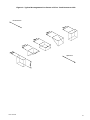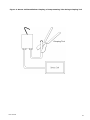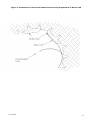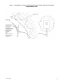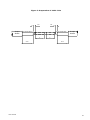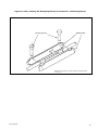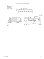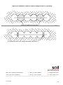
1
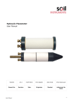
Vibrating Wire Pressure Cell Users Manual Man 034 3.0.2. 04/07/2014 Phillip Day Chris Rasmussen Chris Rasmussen Manual No. Revision Date Originator Checked Authorised for Issue User Manual 1 Contents Section 1 : 1.01 1.02 1.03 Section 2 : 2.01 2.02 2.03 General Information ................................................................................................................. 3 Description ...................................................................................................................................... 3 Operating Principle ........................................................................................................................ 3 Performance .................................................................................................................................... 3 Installation of Pressure Cell .................................................................................................. 4 Test during Installation ................................................................................................................ 4 Cable Connection and Potting ..................................................................................................... 4 Installation in Fill ........................................................................................................................... 4 Section 3 : Installation at Interface between Concrete and Soil .................................................. 6 Section 4 : Installation in Concrete Lined Tunnel................................................................................ 7 4.01 4.02 Section 5 : 5.01 5.02 5.03 Section 6 : 6.01 Preparation of Mortar Pad ............................................................................................................ 7 Installation of Cell ......................................................................................................................... 7 Installation in Rock ................................................................................................................... 8 Preparation of Slot ........................................................................................................................ 8 Installation of Cell and Grouting Down Hole Installations .................................................... 8 Installation of Cell and Grouting Up Hole Installations ......................................................... 8 Compensating Cells for Concrete or Grout Shrinkage ................................................. 9 Compensating the Cell ................................................................................................................. 9 Section 7 : Installation and Termination of Cables ........................................................................... 10 7.01 7.02 7.03 7.03.1.1 7.03.1.2 7.03.1.3 7.03.1.4 General .......................................................................................................................................... 10 Installation in Trenches .............................................................................................................. 10 Cable Jointing ............................................................................................................................... 10 Preparation of the Cable ............................................................................................................ 10 Conductor Connections .............................................................................................................. 10 Fitting Mould ................................................................................................................................. 10 Filling with Resin ......................................................................................................................... 11 Section 8 : Termination of Cables ............................................................................................................ 12 Section 9 : Vibrating Wire Pressure Cell Data Reduction ............................................................... 13 9.01 9.02 Appendix A. The Calibration Certificate ......................................................................................................... 13 Data Reduction............................................................................................................................. 13 Example of Calibration Sheet ........................................................................................... 16 Section 10 : Conversion Factor Chart ........................................................................................................ 17 Section 11 : Troubleshooting ....................................................................................................................... 18 Appendix A. Trouble Shooting Flowchart .............................................................................................. 19 Figure 1: Typical Arrangement for Cluster of Five. Total Pressure Cells ............................................................ 21 Figure 2: Stress Cell Installation Crimping of Compensating Tube Using Crimping Tool ................................... 22 Figure 3: Installation of Stress Cell behind Tunnel Lining Preparation of Mortar Pad ......................................... 23 Figure 4: Installation of Stress Cell behind Tunnel Fixing Cell and Positioned Compensation Tube .................. 24 Figure 5: Preparation of Cable Joint .................................................................................................................... 25 Figure 6: Cable Jointing Kit Wrapping Electrical Connectors and Fitting Mould .................................................. 26 Figure 7: Stress Cell Slot Drilling ......................................................................................................................... 27 Figure 8: Installation of Stress Cells and Supports Prior to Grouting .................................................................. 28 User Manual 2 Section 1 : General Information 1.01 Description The cell consists of a circular or rectangular flat jack formed from two sheets of steel welded around their periphery. The narrow gap between plates is filled with hydraulic oil. The cell is connected to a vibrating wire transducer by a short length of stainless steel tubing, forming a closed hydraulic system. The transducer body is constructed throughout from stainless steel. The sensing wire diaphragm and anchoring tube form a totally sealed independent unit. The coil assembly is coaxially mounted and sealed by epoxy potting. Separation of the above components and transducer outer case are by flexible "O" rings thus preventing case stresses from affecting transducer readings. An armoured cable connects the transducer to a terminal unit or direct to the readout unit. Pressure (stress) cells for installation in concrete or Shotcrete are fitted with a compensating tube, which allows adjustment of initial cell volume to offset concrete shrinkage. 1.02 Operating Principle Pressure applied to the diaphragm causes it to deflect thus changing the wire's tension and resonant frequency. The readout box supplies an electrical pulse to the coil/magnet assembly, which in effect plucks the wire and causes it to vibrate at its resonant frequency. The coil/magnet assembly then acts as a pickup as the oscillations of the wire through the magnetic field induce an alternating current in the coil, which is detected by the readout. The readout converts the sinusoidal alternating voltage to a square wave from which may easily be timed using a frequency oscillator. In this way the period of oscillation may accurately be measured. The relationship between a change in the period of oscillation and the strain of the wire is nonlinear, so to facilitate the reading procedure the MK III Readout converts the period of oscillation to frequency-squared which has a linear relationship to strain. 1.03 Performance The cells have very good long-term stability but they are sensitive to temperature, and allowance for temperature variations may be necessary when incorporating the results. The cells can accommodate a thermistor to monitor temperature if such variations are anticipated. User Manual 3 Section 2 : Installation of Pressure Cell 2.01 Test during Installation Before installation the pressure cell should be subjected to an operational test with the portable readout connected as follows:Lay cell flat on the ground and take zero reading, which should be of a constant raw data value. 2.02 Cable Connection and Potting Pressure cells are usually supplied with 1 metre of armoured cable already connected to the transducer. Additional cable lengths may be added on site using jointing kit. 2.03 Installation in Fill Proper installation of a pressure cell is most important if correct readings are to be obtained. Ideally the material immediately adjacent to the cell should be identical to and at the same density as the machine compacted fill in the general area under investigation. The degree of success experienced in achieving this ideal will depend on the type of soil (e.g., clay, sand, rockfill) and on the care taken in preparing the site, placing the cell and backfilling. Placement in sand is easily carried out but calibrations are relatively unreliable and non-reproductable. Placement in clay is easier and if properly carried out calibrations are fairly reliable. Placement in rockfill introduces two particular problems. Large particles (i.e. greater than approx 5mm) must not be in direct contact with the cell and some compromise in the local grading of the rockfill is necessary. Secondly, hand placing rockfill above and around the cell at the same density and structural arrangement of the particles on the surrounding machine placed fill is difficult and must be done with some care. Horizontally placed cells will be easier to install than those placed in a vertical attitude to measure total horizontal stress. Inclined cells may also be awkward to install. When preparing the site for the installation whether singly or in clusters, it is important to form an excavation 0.5 to 0.75m deep. (The excavation should be backfilled and thoroughly compacted by hand or with light hand-held mechanical plant before any large vehicles pass over this area). It is very important to make the excavation with low angled side slopes so as not to cause large stress concentrations and arching, which occurs with a steep sided pit. The side slopes should not be steeper than 45°. A trench will be required for the cables and should enter the excavation approximately half way along its length. The base of the excavated area, which will have been disturbed by the digging, should be carefully compacted and levelled. This levelling is important as a comparison between each of the cells for the stress analysis will assume all cells at the same level. User Manual 4 The procedure for setting out and placing a typical cluster of five cells is as follows:The area is marked out for each of the five cells with centres at not less than one metre. It is important to align the cells on or parallel to the embankment centre line. At each cell position a hole is carefully excavated by hand and trimmed to shape as shown in figure 1. All protruding stones are removed and the void they leave filled with a graded material smaller than 5mm and carefully re-compacted. To obtain reliable zero readings before, during and just after installation it is preferable to rig up some form of shade to try and keep the temperature constant. Alternatively, the cells can be placed in water filled container and shade temperature adjacent to the cell should be monitored during installation. Ensure that there is enough space for the cell and the transducer in the base of each excavation. Place a little graded material at the position of the underside of the cell and compact thoroughly. Place Cell 1 into its hole, add a further thin layer of graded material over its surface and compact thoroughly. Continue in this manner stopping at intervals to take readings and check the alignment. It is very important that the material is properly compacted around the cell. (In a hot climate, shade the excavation and try to keep the material at its natural moisture content.) Place cell 2 on a 45° surface filled locally with graded material and with a 45° square and level check that the angle is correct. It will be necessary to 'wriggle' the cell to bed the slightly domed face into the fill. Now compact with graded material on top of cell in horizontal layers. Ensure during this part of the work that the cell is kept against the 45° face. The cell may have a tendency to move towards an upright direction due to the wedge shape of the fill - push the top back against the face. For cell 3 place materials around the cell and compact as previously. During this compaction the cell should be kept hard against the prepared face. Continue compacting material around the cell, which will gradually squeeze inwards and over the top of the cell. Do not use too much force in compacting at the centre until 30 to 40mm of fill have been added. Then compact very thoroughly Installation of cells 4 and 5 is exactly as for 2 and 1 respectively but with the cells turned through 90°. Make sure the usual checks on levels, orientation and reading are continually made during their placing. All the above cell holes will require a shallow lead in channel at least 100mm deep for the steel tube, the pressure transducer and the armoured cable. Fill must be carefully compacted by hand around these, in particular where the steel tube is welded to the cell. Backfilling of the excavated area back to formation level must be carried outpneumatic or petrol driven hand operated compactor. Large machines, bulldozers and rollers must not be used until the area is back to formation level. User Manual 5 Section 3 : Installation at Interface between Concrete and Soil Install the cell so that the exposed face is flush with the interface between concrete and soil, either by securing the cell to the formwork, or by fixing a wooden disc to form a recess in which the cell is subsequently embedded. Where cells are to be installed between a cohesive material and a tunnel lining, the location is carefully prepared to provide a smooth bed for the cell. The cell is then pinned to the surface prior to concreting. Diaphragm wall installations may incorporate cells located in the reinforcing cage along with small expendable hydraulic jacks and reaction plates. Lower the cage into the slurry trench. Jack the cells firmly against the trench walls. Pour the concrete. Cells at the base of concrete footings are tied to the soil or rock foundations. Care should be taken to avoid air pockets and retain the cell firmly in contact with the ground during concreting. User Manual 6 Section 4 : Installation in Concrete Lined Tunnel 4.01 Preparation of Mortar Pad Cells placed at concrete/rock interface should be bedded on to a pad of mortar. Where the installation is at the tunnel invert the cell may be bedded directly on to the wet mortar pad. At other positions around the tunnel it will be necessary to cast a concrete pad first using suitable formwork, the cell is later bedded onto the prepared pad. Where cells are to be installed within the tunnel lining, support bars are fitted to the lining reinforcement and the cells mounted on the bars. Care is taken to route the cable and compensation tube so that they will not be damaged. 4.02 Installation of Cell Refer to figures 3 & 4 Installation at positions around the tunnel is achieved by applying a thin layer of motor onto the prepared pad and fixing the cell on the pad with suitable masonry pins. The cell compensating tube is bent to the required position either beneath the formwork and covered with liberally greased paper or passed through the formwork and protected. Securing wires are cut before the shuttering is removed. The armoured cable is routed to a suitable termination point or passed through the reinforcing and shuttering to the inside of the tunnel lining to suit site requirements. On curing the concrete surrounding the cell is liable to shrinkage and therefore full contact with the cell may not be maintained. To restore full contact the cell is compensated as described in Section 6. User Manual 7 Section 5 : Installation in Rock 5.01 Preparation of Slot The slot should be line drilled with a 50mm diameter drill bit at 40mm centres to the required depth using a suitable drilling template rigidly fixed to the rockface to ensure accurate collaring Alternatively the slot may be machined using a diamond wheel saw. 5.02 Installation of Cell and Grouting Down Hole Installations The cell should be placed in the line, drilled slot supported at either side with suitable pre-cast mortar spacers to centralise the cell. Alternatively thin wooden centralising spacers may be used at the ends of the cell. (Refer to figure 8). The cell is fully embedded with grout using a small tremie pipe placed at the bottom of each line-drilled scallop on both sides of the cell. The tremie pipe is raised slowly to keep pace with the grout fill at each scallop position ensuring that no air is trapped. 5.03 Installation of Cell and Grouting Up Hole Installations The cell is positioned into the line-drilled slot with the mortar spacers as described for down hole installations and wooden wedges positioned behind the cell to secure it in the slot. A temporary grout retaining frame and pad is positioned over the slot with rawbolts, the transducer cable and compensating tube are passed through holes in the pad. Grout injection pipes are passed through the plate at each end of the slot such that they just protrude. Small nylon bleed tubes are pushed to the top of each drill hole scallop. All holes in the grout sealing plate are sealed with putty or papier mache prior to grouting. Grout must be mixed as near as possible to the same strength as the rock mass in which the stress cell is to be installed. A swelling agent may be added to the grout mix providing the required modulus is achieved, this will minimise the effect of shrinkage around the cell as the grout cures and maintain full cell contact with the grout. The grout is injected into both grout pipes simultaneously until grout is seen to flow from each air bleed tube. The air bleed tubes are then slowly removed in turn ensuring at the same time that the grout flow is maintained. As each tube is removed, a plug of putty or papier mache is fitted to seal off the grout. The grout-retaining pad is removed when the grout has cured. If a swelling additive is not used in the grout mix it may be found necessary to compensate the cell as described in section 6. User Manual 8 Section 6 : Compensating Cells for Concrete or Grout Shrinkage To restore full contact after concrete or grout cure the compensating tube should be crimped to inject additional oil into the cell to increase its volume. 6.01 Compensating the Cell Taking into account the anticipated stress conditions and strength of the concrete at the time of compensation, select an initial stress value for the cell to ensure an adequate range of measurement. While continually operating the readout, slowly crimp the tube by starting 30mm from the end of the compensating tube (i.e. farthest away from the cell) using the crimping tool, reposition the tool adjacent to the first crimp and re-crimp as needed. Repeat this process progressively towards to cell until the required stress condition is achieved User Manual 9 Section 7 : Installation and Termination of Cables 7.01 General The cable should be laid in a trench deep enough to provide protection from mechanical damage. Alternatively in certain situations the cables may be run in protective conduits or be cast into concrete. 7.02 Installation in Trenches When cables are to be laid in a trench they should be protected for 150mm above and below by compact stone-free material normally sand, silt or clay. Although sand is often most convenient to use, only silty clay or clay should be used where the creation of a drainage path would be undesirable. Where the trench passes through the impervious clay core of an embankment dam additional cut-offs across the trench may be necessary. If the trench is to be backfilled using rock fill or coarse granular material the thickness of the protective layer over the cables should be increased to 250mm. The cables should be laid loosely in the trench, snaked to prevent strain due to ground movements; in most cases a wavelength of 3m and an amplitude of 200mm should be sufficient. In certain cases it may be advisable to separate the cables from each other in the base of the trench. The cables should be looped on crossing an interface where differential ground movements might be anticipated. The cables should also be looped at cable joints. The cables should be identified using coloured P.V.C. tape applied at regular intervals. The correct functioning of the instrument should be checked before backfilling the trench. Compaction of backfill should be carried out using only hand-operated equipment. It may be advisable to clearly mark out or survey the position of the instrument trench, particularly if there is to be further excavation or borehole drilling in the vicinity. A record of the trench position and depth should be kept. 7.03 Cable Jointing It is desirable to minimise cable joints, but where they are unavoidable a special joint kit may be supplied. The effectiveness of this joint largely depends on the care with which the jointing operation is carried out. 7.03.1.1 Preparation of the Cable Thoroughly scrape all wax and dirt from each cable and for approximately 150mm. Prepare the cable ends exactly as shown in Figure 5. Stagger the individual conductor connections. 7.03.1.2 Conductor Connections Use the crimped connectors to join the conductors and use the electrical insulation tape to wrap the connectors. Stretch the tape to half its original width and apply one layer half lapped over connector area only (Figure 6). Do not warp the tape beyond the pencilled area. 7.03.1.3 Fitting Mould Trim the ends of the mould with a sharp knife to suit the diameter of the cable. Hold he mould halves in place centred over the splice. Snap both halves together and fit the pouring User Manual 10 spouts in the holes. Ensure that both seams are completely snapped together. Tape the ends of the mould body to form a seal. 7.03.1.4 Filling with Resin Mix the resin thoroughly and maintaining the mould in a level position, spouts uppermost, pour the resin through one spout until both spouts are completely filled. When the resin has solidified and cooled remove the spouts. NOTE: User Manual In cold weather (below 15°C) the resin becomes very viscous. It is therefore advisable to keep the resin in a warm place prior to mixing. Mix the compound until its temperature starts to rise, this decreases the viscosity. 11 Section 8 : Termination of Cables The cables are normally terminated in a 5-channel terminal box or 12 and 24 channel terminal units. The cables enter through waterproof glands. The terminal box has a cover secured by four screws whereas the terminal units have a hinged lid. The cables are terminated as follows:Unscrew the cover or open the lid as appropriate. Unscrew the four fixing screws holding the terminal panel and carefully remove it without straining the connecting leads. Prepare the cables by stripping and cutting back 20cm approximately of the outer insulation and armour. Remove the rubber packing and strip back 5cm of the conductor insulation. Slacken the entry glands and insert the cables. Make connections to the contact block (details of colour coding supplied with each instrument). Retighten the glands to grip the cables. Replace the terminal panel and secure. check connections. User Manual Connect the readout to each instrument in turn to 12 Section 9 : Vibrating Wire Pressure Cell Data Reduction 9.01 The Calibration Certificate The end of this section shows example of the Calibration Certificate as supplied with each vibrating wire pressure cell. 9.02 Data Reduction The pressures recorded by the cells are relative (i.e. the cells are measuring changes in pressure, not absolute pressure) since they have an internal pressure at zero load. The initial readings are recorded at the following stages:In Fill At Interface - in controlled conditions prior to placing the cell. - after the concrete has cured and its heat dissipated. In Tunnel Linings - after concrete has cured and after compensation (where necessary). In Rock - after the grout has cured and compensation has been carried out. Pressure changes are either calculated using the formula on the instrument's calibration sheet or calculated and recorded automatically by the data logger, both as changes from the base reading. Total pressure cells are usually installed with an associated piezometer. Effective pressure is determined by subtracting the pore pressure from the total pressure. An example of a calibration certificate can be found at the end of this section with a selection of Gauge Constants enabling the operator to read and log data directly in the ENGINEERING units desired. The mathematical relationship between the frequency of vibration of a tensioned wire and the force applying the tension, is an approximate straight line relationship between the square of the measured frequency and the applied force. Engineering units of measurement maybe derived from the frequency-based units measured by vibrating wire readouts, in 3 traditional ways:From ‘Period’ units and from ‘Linear’(f^2/1000) units using two methods: a simple Linear equation or a Polynomial equation. Calculation using ‘Period’ units. The following formula is used for readings in ‘Period’ units. E = K (10^7/P0^2 – 10^7/P1^2) Where, E is the Pressure in resultant Engineering units, K is the Period Gauge Factor for units of calibration (from the calibration sheet), P0 is the Period ‘base’ or ‘zero’ reading P1 is the current Period reading. User Manual 13 This method of calculation is used by the Soil Instruments Vibrating Wire loggers’ (models RO-1VW-1 or 2 and with serial numbers starting VL or TVL) internal processors’, for calculating and displaying directly on the loggers’ LCD screen, the required Engineering based units. The loggers’ require ‘Period’ base or zero reading units for entering into their channel tables, to calculate and display correctly the required engineering units. If an Engineering-based unit is required other than the units of calibration, then the correct K factor will have to be calculated using the standard relationship between Engineering units. For example, if the units of calculation required were in KGF/Cm2 and the calibration units were kPa, we can find out that 1kPa is equal to 0.01019 KGF/Cm2, so we would derive the K factor for KGF/Cm2 by multiplying the K factor for kPa by 0.01019 Please see conversion factors in Section 10. Calculation using Linear units. The following formula is used for readings in ‘Linear’ units. E = G (R0 – R1) Where, E is the resultant Engineering unit, G the linear Gauge factor for the units of calibration (from the calibration sheet), R0 is the Linear ‘base’ or ‘zero’ reading R1 is the current Linear reading. Again the Linear gauge factor for units other than the units of calibration would need to be calculated using the same principles as stated in the last paragraph of the ‘Period unit’ section. Linear unit calculation using a Polynomial equation. Linear units maybe applied to the following polynomial equation, for calculation of Engineering units to a higher order of accuracy. E = AR1^2 + BR1 + C Where, E is the resultant Engineering unit, A, B and C the Polynomial Gauge factors A, B and C, from the instrument’s calibration sheet, R1 is the current Linear reading. The value C is an offset value and relates to the atmospheric pressure experienced by the pressure cell at the time of calibration. This figure will have changed at the time of installation due to changes in altitude or barometric pressure, so C should be re-calculated at the installation time as follows: C = - (AR0^2 + BR0) Where, User Manual 14 A and B are as above, R0 is the Linear ‘base’ or ‘zero’ reading. Please note that the sign of the re-calculated value of C, should be the same as the original value of C, so if the original is negative then the recalculated value should also be negative. Conversion to engineering units other than the units of calibration, would best be done after conversion, using a factor calculated using the same principles as stated in the last paragraph of the ‘Period unit’ section. Please see conversion factors in Section 10. User Manual 15 Appendix A. Example of Calibration Sheet User Manual 16 Section 10 : Conversion Factor Chart Pressure, Stress & Modulus of Elasticity MN/m2 kp or kN/m2 or kgf/cm bar atm or kPa 2 MPa 1 1000 10.197 10.000 9.869 1.019 x 9.87 x 0.001 1 0.0100 -2 10 10-3 9.807 x 98.07 1 0.9807 0.9678 10-2 0.100 100.0 1.0197 1 0.9869 0.1013 101.33 1.0332 1.0132 1 9.788 x 9.983 x 9.789 x 9.661 x 9.7885 -3 10 10-2 10-2 10-2 2.983 x 3.043 x 2.984 x 2.945 x 2.9835 10-3 10-2 10-2 10-2 1.333 x 1.3595 1.333 x 1.315 x 0.1333 -4 10 x 10-3 10-3 10-3 0.1073 107.3 1.0942 1.0730 1.0589 6.895 x 7.031 x 6.895 x 6.805 x 6.895 -3 10 10-2 10-2 10-2 4.788 x 4.788 x 4.883 x 4.788 x 4.725 x 10-5 10-2 10-4 10-4 10-4 User Manual m H2O ft H2O mm Hg tonf/ft2 psi or lbf/in2 lbf/ft2 102.2 7500.6 9.320 145.04 20886 0.1022 0.3352 7.5006 0.0093 0.14504 20.886 10.017 32.866 735.56 0.9139 14.223 2048.1 10.215 33.515 10.351 33.959 750.06 760.02 14.504 14.696 2088.6 2116.2 1 73.424 0.9320 0.9444 9.124 x 10⁻² 2.781 x 10⁻² 1.243 x 10⁻³ 1 6.426 x 10⁻² 4.464 x 10⁻⁴ 1.4198 204.45 335.2 3.2808 0.3048 1 1.362 x 4.469 x 10-2 10-2 10.960 35.960 22.377 1 804.78 0.7043 2.3108 51.714 4.891 x 1.605 x 10-3 10-2 0.3591 0.43275 62.316 1.934 x 10⁻² 15.562 2.7846 2240.0 1 144.00 6.944 x 10⁻³ 1 17 Section 11 : Troubleshooting If a failure of any Vibrating Wire transducer or the electrical cable is suspected, the following steps can be followed. The transducers themselves are sealed and cannot be opened for inspection. The “Troubleshooting Flowchart” should also be followed if any instrument failures are suspected. The steps below and the Troubleshooting Flowchart are applicable generally to any vibrating wire instrument. STEP 1 Before any of the following steps are followed, the portable data logger should be used to verify the stability of the reading and the audio signal from the portable logger should be heard. An unstable (wildly fluctuating) reading from a transducer, or an unsteady audio signal are both indications of possible problems with instruments or their related electrical cables. If a portable data logger is giving faulty readings or audio signals from all transducers, a faulty readout unit must be suspected. Another readout unit should be used to check the readings from the transducers and Soil Instruments should be consulted about the faulty readout unit. STEP 2 The resistance across the two conductors of the electrical cable should be checked. This can be done using a multimeter device across the two exposed conductors if the cable has not been connected to a terminal cabinet, or can be done just as easily across the two conductors if the instrument has been connected to such a terminal (or datalogger). The resistance across the two conductors should be approximately of the order of 120 to 180. The majority of this resistance will come from the transducer (say approximately 130). Before proceeding to Steps 3 and 4, the continuity should be checked between conductors and earthing screen of the electrical cable. If continuity exists, a damaged cable is confirmed. STEP 3 If the resistance across the two conductors is much higher than the values quoted in “STEP 1” (or is infinite), a severed cable must be suspected. STEP 4 If the resistance across the two conductors is much lower than the values quoted in “STEP 1” (say 80 or less) it is likely that cable damage has occurred causing a short in the circuit. STEP 5 If the resistance is within the values quoted in “STEP 1” (i.e. 120 to 180), AND no continuity exists between conductor and earth screen and on checking the reading from the transducer, it proves to be still unstable or wildly fluctuating, it must be assumed that the integrity of the circuit is good. A faulty transducer could be suspected if neighbouring construction activities do not account for the anomaly, Soil Instruments should be consulted. If the point at which the cable is damaged is found, the cable can then be spliced in accordance with recommended procedures. User Manual 18 Appendix A. Trouble Shooting Flowchart R less than 80 User Manual 19 User Manual 20 Figure 1: Typical Arrangement for Cluster of Five. Total Pressure Cells Downstream Upstream User Manual 21 Figure 2: Stress Cell Installation Crimping of Compensating Tube Using Crimping Tool Crimping Tool User Manual 22 Figure 3: Installation of Stress Cell behind Tunnel Lining Preparation of Mortar Pad User Manual 23 Figure 4: Installation of Stress Cell behind Tunnel Fixing Cell and Positioned Compensation Tube User Manual 24 Figure 5: Preparation of Cable Joint 5.00 Scrape Sheath Cut Sheath Back Cut Sheath Back A 25.00 User Manual 5.00 Scrape Sheath A 25.00 25 Figure 6: Cable Jointing Kit Wrapping Electrical Connectors and Fitting Mould Pouring Spouts Mold Bodies IMPORTANT: Cables and Connector Must be Centerd in Mold. User Manual 26 Figure 7: Stress Cell Slot Drilling Note:Commence Drilling Of Slot With Template On 'CRS' 'A' For Whole Length Repeat Operation Template On 'B' 'CRS' 50mm Ø 40mm Ø Length To Suit Size Of Stress Cell 55mm ØHoles B Line Drilled Holes 500mm Deep Two Position Fixing Holes 55mm Ø Holes A A Rawlbolt Fixing For Template 80mm crs Drill Bit Location Holes 1 B 2" Fig 1 User Manual 27 Figure 8: Installation of Stress Cells and Supports Prior to Grouting PRECAST MORTAR SPACERS Fig 5 Fig 5a ALTERNATIVE METHOD USING WOODEN SPACERS Bell Lane, Uckfield, East Sussex t: +44 (0) 1825 765044 e: [email protected] TN22 1QL United Kingdom f: +44 (0) 1825 744398 w: www.itmsoil.com Soil Instruments Ltd. Registered in England. Number: 07960087. Registered Office: 5th Floor, 24 Old Bond Street, London, W1S 4AW User Manual 28