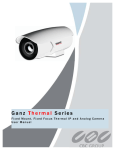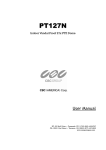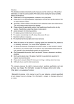
1
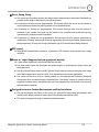
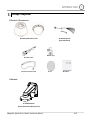
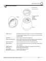
PT118XT-HD Outdoor Vandal Proof 18X IP HD PTZ Dome UUser Manual NY: 55 Mall Drive • Commack, NY 11725 (800) 422-6707 &$6:HVWHUQ$YH • Torrance, CA 9050 (877) 407-9555 www.computarganz.com CAUTION RISK OF ELECTRIC SHOCK DO NOT OPEN CAUTION: TO REDUCE THE RISK OF ELECTRICAL SHOCK, DO NOT OPEN THE COVERS. THERE ARE NO USER SERVICEABLE PARTS INSIDE. REFER SERVICING TO QUALIFIED SERVICE PERSONAL This symbol (lightning flash with arrowhead) is intended to alert the user to the presence of un-insulated "dangerous voltage" within the product's enclosure that may be of sufficient magnitude to constitute a risk of electric shock to persons. This symbol (exclamation point) is intended to alert the user about the presence of important operating and maintenance (servicing) instructions in the literature accompanying the appliance. Megapixel Speed Dome Camera Instruction Manual 2/37 NOTICE Important Safety Guide 1. Read, heed and follow all the Instructions Read all the safety and operating instructions before using the product. 2. Keep this manual Keep this manual for future reference. 3. Attachments / Accessories Use only the attachments or accessories specified by the manufacturer. 4. Installation Do not install near any heat resources such as radiators, heat registers, stoves, or other apparatus including amplifiers that product heat. Improperly installed product may fall, cause serious injury to a child or adult and damage the product. Do not block any ventilation holes or openings. Install in accordance with the manufacturer‟s instructions. Use only with the cart, stand, tripod, bracket, mounting devices, or table specified by the manufacturer. Installation should be done only by qualified personnel and conform to all the instructions by the manufacturer. Refer all servicing to qualified service personnel. 5. Power source This product should be operated with the same type power source as indicated on the marking label Caution 1. Operating 1. Before using, make sure that the power supply and associated parts are properly installed. 2. While operating, if any abnormal condition or malfunction is observed, stop using the product immediately and then contact your local dealer. 2. Handling 1. Do not disassemble or tamper with the parts inside the product. 2. Do not drop or subject the product to shock and vibration as this can damage the product. 3. Care must be taken when you clean the clear dome cover. Especially, scratches or dust on the cover will ruin the quality of the product. 3. Installation and Storage 1. Do not install the product in areas of extreme temperature, which exceed the allowable range. 2. Avoid installing in high humid or dusty environments. 3. Avoid installing in places where radiation is present. 4. Avoid installing in places where there are strong magnetic fields and electric signals. 5. Avoid installing in places where the product would be subject to strong vibrations. Megapixel Speed Dome Camera Instruction Manual 3/37 CONTENTS ① Introduction Features Package Components Main Part Description DIP Switch Setup 6 8 9 10 ② Installation Installation using Wall Mount Bracket Wiring and Cabling 13 14 ③ Configuration Web-View Main Screen 18 Video & Audio Configuration Codec ____ Video Audio Privacy zone 19 20 21 22 PTZ Configuration 1. Basic configuration 2. RS 485 configuration 3. Preset & Preset Sequence 4. Swing 5.Pattern 6.Group Tour Megapixel Speed Dome Camera Instruction Manual 23 23 24 25 26 27 4/37 CONTENTS Event Configuration 1. Sensor and Relay 2. Emergency Alarm 28 29 Network Configuration 1.IP Setup 2.Dynamic DNS 3. Live Protocol 4. IP Filtering 30 30 31 31 System Configuration 1.Upgrade 2.Time & Date 3. Event Mail 4. User Management 32 32 33 34 ④ Specifications Specifications Dimension Megapixel Speed Dome Camera Instruction Manual 35 37 5/37 INTRODUCTION 1 Feature This „IP-server‟ supports remote images, sound, setup and control of camera functions though IP Networks such as LAN, ADSL/VDSL, and Wireless LAN Camera Specifications Image Sensor : 1/3" Megapixel solid State Progressive Scan CCD. Zoom : 18 Optical Zoom WDR function (Wide Dynamic Range) SNR(Super Noise Reduction) function You can adjust focus to PTZ camera with 'Semi-Auto Focus function' included Auto-Focus, Manual Focus. Video Supports H.264, MPEG4,MJPEG (H.264 is the latest high efficiency compression format) Various Resolutions : 1280720 ~ 256144 Supports a wide range of bandwidth control : 50kbps ~ 8Mbps Supports HD-SDI(HDCCTV) video output Audio Supports various transmission modes : Simplex (IP-server → Client PC / Decoder, Client PC / Decoder → IP server) and full-duplex Network Supports static IP, dynamic IP (DHCP), and PPPoE Supports 1:1 and 1:N connection Supports Multicast transmission Supports various network protocol: TCP/IP, UDP, Multicast, DHCP, SMTP, HTTP, SNMP, RTP, RTSP Powerful Pan/Tilt function MAX. 360/sec High Speed Pan/Tilt movement. With the Vector Drive Technology, Pan/Tilt motions are accomplished along the shortest path. As a result, the time to view a target is remarkably short and the video output displayed feels very natural for monitoring. With the Micro-Stepping Control Technology, video movements still look very smooth at high zoom magnification. During operation via a controller the camera can be moved by as little as 0.05/sec. Hence it is very easy to make the camera focus on desired target even at high zoom magnification. Additionally it is easy to make the camera focus on desired positions with zoom-proportional pan/tilt movement. Megapixel Speed Dome Camera Instruction Manual 6/37 INTRODUCTION 1 Preset, Swing, Group You can set up to 99 preset positions, and assign camera image setting to each preset. Additional it is possible to also assign a label/name to each preset position. A maximum of 8 Swing sets are programmable. This function allows the user to set the camera to move repetitively between two preset positions at a programmed speed. A maximum of 4 Patterns are programmable. This function allows the user to set the camera to memorize a path (mostly curve path) by the joystick of the controller and record the trajectory operated by the joystick as closely as possible. A maximum of 8 Group sets are programmable. This function is that the camera memorizes the combination of Presets, Pattern and/or Swings sequentially and runs these Presets, Pattern and/or Swings repetitively. A Group can be any combination of up to 20 Preset/Pattern/Swing functions. PTZ control Using RS-485 communication connection, a maximum of 255 cameras can be connected to a single controller. Alarm in/ output (Supported only on appropriate models) 3 alarm sensor inputs and 1 alarm relay output are available. The alarm sensor inputs are decoupled with photo-couplers to avoid external electric noise and shock protection. Both N.O.(Normal Open) sensors and N.C.(Normal Close) sensors can be used and the signal range of the Alarm output can be from DC 5.0V to 12.0V depending on the various applications. The camera can be set to move to a Preset position or to run functions such as Pattern, Swing and Group when there are external sensor activations. Also “Post Alarm” function is possible, which is supposed to activate after a user-defined time period and sequentially in succession to the action by external sensor activations Designed for various Outdoor Environments and Easy Installation The fans and heaters are built-in to the camera for cold and hot temperature environments. Also idealistic case design protects the camera from wet and dusty environments. (IP67) The camera is designed for easy to installation and maintenance. Megapixel Speed Dome Camera Instruction Manual 7/37 INTRODUCTION Package Component Product & Accessories Default Accessories [Main Cable,Wrench] Main Body & Clear Dome Cover Audio Cable LAN Crossover Cable BNC (2ea) CD Manual Brackets Wall Mount Bracket [Screws :Machine M515,Hex Lag #1450] Megapixel Speed Dome Camera Instruction Manual 8/37 1 INTRODUCTION 1 Main Part Description Dome Cover Do not remove the protection vinyl from the dome cover before finishing all the installation processes. This is to protect the dome cover from scratches or dust. DIP Switch Drop Prevention Spring Used to set up the camera IDs and protocols. Used to protect the product from being dropped by connecting safety wire of bracket to hook of main body when being installed. Mount Screw Hole Used to assemble the main body with a bracket using screws. Main Connector Used for the power wire, the video cable and the RS-485 communication cable connection. LAN Connector Used for Ethernet cable connection. (Only supported on IP models) Audio Port Video (BNC) IP Module Reset Switch Used for Audio In/Out connection Used for HD-SDI cable connection. Used for system rebooting Megapixel Speed Dome Camera Instruction Manual 9/37 INTRODUCTION 1 DIP Switch Setup Before installing the camera, set up the DIP switches to configure the camera ID and the communication protocol. Camera ID Setup The ID number of camera is set using a binary number. Examples shown below. The range of ID is 1~255. UDo not use 0 as camera IDU. Factory default of Camera ID is 1. If you want to control a certain camera, you must match the camera ID with Cam ID setting of DVR or Controller. ON ON 1 2 3 4 5 6 7 8 Pin 1 2 3 4 5 6 7 8 Pin 1 2 3 4 5 6 7 8 ID 1 2 4 8 16 32 64 128 ID 1 2 4 8 16 32 64 128 1 on off off off off off off off 11 on on off on off off off off 2 off on off off off off off off 12 off off on on off off off off 3 on on off off off off off off 13 on off on on off off off off 4 off off on off off off off off 14 off on on on off off off off 5 on off on off off off off off 15 on on on on off off off Off 6 off on on off off off off off 16 off off off off on off off off 7 on on on off off off off off 17 on off off off on off off off 8 off off off on off off off off 18 off on off off on off off off 9 on off off on off off off off 19 on on off Off on off off off 10 off on off on off off off off 20 off off on off on off off off Megapixel Speed Dome Camera Instruction Manual 10/37 INTRODUCTION Pin 1 2 3 4 5 6 7 8 Pin 1 2 3 4 5 6 7 8 ID 1 2 4 8 16 32 64 128 ID 1 2 4 8 16 32 64 128 21 on off on off on off off off 31 on on on on on off off off 22 off on on off on off off off 32 off off off off off on off off 23 on on on off on off off off 33 on off off off off on off off 24 off off off on on off off off 34 off on off off off on off off 25 on off off on on off off off 35 on on off off off on off Off 26 off on off on on off off off 36 off off on off Off on off off 27 on on off on on off off off 37 on off on off Off on off off 28 off off on on on off off off 38 off on on off Off on off off 29 on off on on on off off off 39 on on on off Off on off off 30 off on on on on off off off 40 off off off on Off on off off 1 Communication Protocol Setup Select an appropriate Protocol using the below DIP switch combinations. ON ON 1 Switch Mode 2 3 4 Protocol P0 P1 P2 (Pin 1) (Pin 2) (Pin 3) OFF OFF OFF PELCO-D, 2400 bps ON OFF OFF PELCO-D, 9600 bps OFF ON OFF PELCO-P, 4800 bps ON ON OFF PELCO-P, 9600 bps Others Reserved Match the camera protocol with the camera protocol setting of your DVR or controller to control the camera. Adjust the DIP switch after turning off the camera. If you changed the camera protocol by changing the DIP S/W, the change will be effective after you reboot the camera. The factory default protocol is “Pelco-D, 2400 bps” Megapixel Speed Dome Camera Instruction Manual 11/37 INTRODUCTION 1 Terminal Resistor Setup The terminal resistor is used for the following cases. ON ON 1 2 3 4 In case that the control cable length between a camera and a controller is relatively very long (1:1 Connection) If the communication cable length is very long, the electrical signal will bound in the terminal point. This reflected signal causes distortion of original signal. Accordingly, the camera can then be out of control. In this case, the terminal resistor of both sides i.e. the camera and the controller must be set to „ON‟ state. In case that multiple cameras are connected to a controller Due to similar reasons with the case 1, the terminal resister of the controller and the last camera must be set to „ON‟ state. The last camera means the camera farthest in cable length from the controller. Do not turn on the terminal resistor of more than one camera on the same communication cable. Megapixel Speed Dome Camera Instruction Manual 12/37 INSTALLATION Installation using Wall Mount Bracket ①Make a hole diameter between 30~40mm on the mounting surface to pass the wire(s) and cable(s) through the mounting surface. (In case of the wiring and cabling through the mounting surface only) Then prepare the wall mount bracket. Pull the wire(s) and cable(s) for the system as below. Attach the wall mount bracket to the mounting surface. ② Pull the wire(s) and cable(s) for the system through. Before connecting cables, hook the safety wire inside the adaptor to the cameras main body. Wire the cable(s) to the camera connections. After assembly, attach the camera to the bracket with 3r screws. (Machine M515) (Hex Lag #1450) ③ Assemble the dome cover with safety wire of main body and screw the main body with dome cover. After assembly, remove protection vinyl from dome cover. Important Notice Before starting the installation,make sure that the Camera ID and Protocol are set up correctly. Megapixel Speed Dome Camera Instruction Manual 13/37 2 INSTALLATION Wiring and Cabling Port Description Main Cable Port Pin Number 1 2 3 4 5 6 7 8 9 10 Audio Cable Port Pin Number 1 2 3 Cable Color Black Brown Red Orange Yellow Green Blue Violet Gray White RS-485 + RS-485 DC 12V Ground OUT 2 (Relay Output 2) OUT 1 (Relay Output 1) IN COM (Sensor Input Common) IN 1 (Sensor Input 1) IN 2 (Sensor Input 2) IN 3 (Sensor Input 3) Cable Color Signal RCA(Yellow) Audio IN Audio GND Audio OUT RCA(White) Megapixel Speed Dome Camera Instruction Manual Signal 14/37 2 INSTALLATION 2 Power Description Carefully check the voltage and current for the power supply. The input power is indicated on the back of main unit. Rated Power DC12V Model IP Model InputVoltage Range Current Consumption DC 12V 3.0 A In cases where the length of the power wire is very long, there may be voltage drop and the system may not work properly. Make the length of the power wire as short as possible. RS-485 Communication For PTZ control, connect the cable(s) to your keyboard or DVR. To connect multiple cameras to a single controller, RS-485 communication should be connected in parallel as shown below. Megapixel Speed Dome Camera Instruction Manual 15/37 INSTALLATION 2 Sensor Input Before connecting sensors, check the sensor driver voltage and output signal type. Since sensor output signal types are divided into Open Collector and Voltage Output types in general, the cabling must be installed properly depending on the signal type. Signal Description IN COM (GND) Connect SENSOR COMs to this port(GND) as shown in the circuit above. IN1, IN2, IN3 Connect output of sensors for each port as shown in the circuit above. If you want to use Alarm Input, the type of sensor must be selected. The sensor types are Normal Open and Normal Close. If the sensor type is not selected properly, alarm activation will occur opposite of what is desired Normal Open Output Voltage is high state when sensor is activated Normal Close Output Voltage is high state when sensor is not activated Megapixel Speed Dome Camera Instruction Manual 16/37 INSTALLATION Relay Output The maximum loads are as follows. Power Type Maximum Load DC Power AC Power MAX. DC 24V, 1A MAX. AC 125V, 0.5A Megapixel Speed Dome Camera Instruction Manual 17/37 2 CONFIGURATION Web-View Main Screen Setup This menu contains the configurations for IP camera operation. Export Image This function saves the current image on the screen as a JPG file. Print This function prints out the current image on the screen. Pan/Tilt Opens the display for PTZ Control and allows access to the PTZ setup. Camera Indicates or selects the current video channels on the main screen. Alarm Indicates when sensor is active. Control Indicates or selects a Relay is active. Audio Select to use the audio data transmission from server. Megapixel Speed Dome Camera Instruction Manual 18/37 3 CONFIGURATION 3 Audio Out When button is activated, audio is transmitted from web-viewer to camera. Full Screen Full screen mode is available when you click button. If you want to return to general mode from full screen mode, you should press the ECS button on your keyboard. Video and Audio configuration 1. Codec - Use to setup the resolution, channel name, codec, quality and fps for encoding images Resolution Setup the resolution for the main and sub channels. It supports 8 different resolutions in 16:9 and 4:3 ratios for each channel. Channel name Setup the name for the main channel and sub channels. Codec Use to set the codec as H.264, MPEG4 or MJPEG. Bit rate Select the bit rate to encode with H.264 and MPEG4, the bit rate is related with quality. The units used for bit rate data is in Kbps. Frame rate Select the frame rate to encode this can be set up between 0 to 30fps. JPEG quality Select the JPEG image quality. This can be set between Low to Super Fine. Megapixel Speed Dome Camera Instruction Manual 19/37 CONFIGURATION 3 2. Video White Balance This controls the color balance for color temperature. It has two modes (Auto/Manual mode). The color balance is automatically controlled on Auto mode. You can manually set red and blue balance on Manual mode. Auto Exposure AE mode: This is the basic mode for Auto Exposure. AER1, AER2: The mode adds the 'IR Removal function' to the AE mode. The IR function works with high sensitively on AER1 and with medium sensitively on AER2. A E+ : This mode adds the 'DSS function' on to the AE mode. AER+1, AER+2, AER+3: These modes apply different levels of the 'IR Removal function' and 'DSS function' on to the AE mode. These functions work in High / Medium/ Low sensitively on AER+1 / +2/ +3 respectively. Focus The Auto mode, automatically controls the focus. The Manual mode, the user sets the focus manually by user. Megapixel Speed Dome Camera Instruction Manual 20/37 CONFIGURATION 3 3. Audio - Use to set the Audio In/Out and network transfer. Audio Input Gain Use to set the amount of gain required on the Audio Input. Audio Output Buffering time Use to set the buffering time when audio data is transfer between client and remote server. We recommend setting the buffering time longer if sound is bad or network is unstable. Volume Select the volume for the Audio Output. Network transfer. This function allows the transfer of audio data without considering video data transmission Megapixel Speed Dome Camera Instruction Manual 21/37 CONFIGURATION 3 4. Privacy zone - To protect others‟ privacy, 4 Privacy Masks can be created on the arbitrary position to hide objects such as windows, shops or private house. (Max. 8 Privacy Masks on a screen when you set the gap more 50° between each masks) Privacy Zone Mask Setup Select a Mask number to program. If the selected mask has already data, the screen displays what was programmed. Move your camera to the required position for masking using the PTZ Controller. Adjust the mask size required. Click the Set button. Then [Undefined] will disappear and the hidden selected areas will turn to gray Delete Privacy Zone Mask Select a Mask number to delete. Click the Delete button. Then [Undefined] will be displayed and recover normal images erasing hidden gray parts. Megapixel Speed Dome Camera Instruction Manual 22/37 CONFIGURATION 3 PTZ configuration 1. Basic configuration - Use to set the basic PTZ operation, such as to control the speed of Pan/Tilt/Zoom/Focus and Auto Flip function. 2. RS485 configuration - Setup to control PTZ with external Controller devices though RS485 port. You should set the speed, protocol and address to match the controller devices. Protocol mode Use to set the speed, protocol and address instead of using external DIP switch settings. On Software, the camera values can be set via Web browser. Speed/ Protocol/ Address You should set values to match Controller devices. Megapixel Speed Dome Camera Instruction Manual 23/37 CONFIGURATION 3 3. Preset and Preset Sequence Preset Preset setup ① Move camera to the display the area of interest using PTZ Controller. ② Select preset number and Dwell Time. ③ Click „Set button‟. Then preset setting is finished and the [Undefined] will disappear. Clear Preset ① Select preset number to delete. ② Click „Clear button‟. Then [Undefined] will be displayed again. Move Preset ① Select preset number to move. ② Click „Move button‟. Then the camera view will moved to the assigned area for the preset number. Preset Sequence Use to assign multiple presets in a regular sequence. The camera will move between assigned presets and hold as long as the Dwell time set, then the camera will move onto the next preset in the sequence. Megapixel Speed Dome Camera Instruction Manual 24/37 CONFIGURATION 3 4. Swing Swing setup ① ② ③ ④ Select the swing number Set the first position number to the 1st Position, the second position number to 2nd position. Set the Speed and Dwell Time for swing. Click „Apply button’. Then Swing setting is finished and [Undefined] will disappear. Delete Swing ① Select the swing number to delete. ② Set the value as “Not used” in 1st Position and 2nd Position and click “Apply button‟. Then Swing is deleted and [Undefined] will be displayed for assigned swing numbers. Run Swing ① Select swing number to run. ② Click „Run Swing button’. When the swing function is running, you can check the swing speed and Dwell time. Direction - Select the pan direction for swing. It supports 3 types of pan directions. (Shortest, Clockwise and Counter Clockwise) CGI preset commands from 41 to 48 are assigned to run swing. Megapixel Speed Dome Camera Instruction Manual 25/37 CONFIGURATION 3 5. Pattern Pattern setup ① ② ③ ④ Select the pattern number to set. Move to the field of view to the start position using PTZ Controller. Click „Set Pattern Start button‟ to begin Pattern recording. The when you move camera using PTZ Controller the function will memorized the speed and path. ⑤ Click „Set Pattern Stop‟ button. Then Pattern setting is finished and [Undefined] will disappear. . Delete Pattern ① Select the pattern number to delete.. ② Click „Delete Pattern button‟. Then selected Pattern is deleted and [Undefined] will be displayed again. Pattern action ① Select the pattern number to run. ② Click „Run Pattern button‟. Then the assigned pattern activate. CGI preset commands from 31 to 34 are assigned to run pattern. Megapixel Speed Dome Camera Instruction Manual 26/37 CONFIGURATION 6. Group Tour Group number 8 groups can be setup. (From 1 to 8) . Action Select which action to set from choice of Presets, Swings or Patterns. . Dwell Time Set the dwell time between the Preset, Swing or Pattern to the next action , Speed Select the camera speed for Preset or Swing. Repeat Set the repeat frequency for the action. CGI preset commands from 51 to 58 are assigned to run group tour. Megapixel Speed Dome Camera Instruction Manual 27/37 3 CONFIGURATION 3 Event setup 1. Sensor and Relay Sensor Use Select to activate/deactivate a sensor. Type Select the sensor type between NO/NC. Delay Set the delay time after sensor is working. During the delay time the Camera does not treat another sensor signal as the event and will ignore it. Camera Select the camera to connect. The selected camera stream will be used for Sensor Preset, Emergency Alarm. Preset Select the preset position for the camera to the move when sensor has been activated Relay Select the relay to work when sensor has been activated. Duration Set the duration that the Relay remains active. Relay activation Use Check the box to enable/disable the relay activation. Name Enter the name for the relay device. Activity Time Set the activity time. The relay can only work during the assigned time. Megapixel Speed Dome Camera Instruction Manual 28/37 CONFIGURATION 2. Emergency Alarm Emergency alarm transfers video data to an EA server when sensor event happens, Stream Select the priority of the EA stream when an event occurs. Site Code Input a site code/name for the camera, this is transmitted to EA server during an event. Transfer Time Select the duration that the video is streamed to the EA server. EA Server List Input the EA server IP address(s) and port number(s) to transfer emergency data and video. Megapixel Speed Dome Camera Instruction Manual 29/37 3 CONFIGURATION 3 Network Setup 1. IP Setup - Set the network values for the Camera. Select either DHCP, PPPoE or Static IP. Then enter the DNS server details and change port number if required. The settings will be applied to the new values after rebooting the system 2. Dynamic DNS - DDNS allows the use of a domain name for network connection instead of an assigned IP address. This function is very useful when you use a dynamic IP protocol such as DHCP or PPPoE. Megapixel Speed Dome Camera Instruction Manual 30/37 CONFIGURATION 3. Live Protocol - Select the method used to transfer video, audio data to remote clients, 4. IP filtering - Setup the network authority by allowing / restricting the incoming connections. All Allow This option allows all incoming connections. Allow Input the specific IP addresses allowed to connect. Deny Input specific IP addresses unauthorized to connect. Megapixel Speed Dome Camera Instruction Manual 31/37 3 CONFIGURATION 3 System configuration 1. Upgrade This menu allows the User to upgrade the camera with the latest firmware updates. The screen displays updating status on „Upgrade Status message window‟. The upgrade firmware version will be applied after rebooting system. 2. Date & Time Use this menu to set the date, time and local time zone for the camera. Megapixel Speed Dome Camera Instruction Manual 32/37 CONFIGURATION 3. Event mail The camera will sent event information by e-mail when an event occurs. Use Event Mail Use this option to enable/disable the function. Events Select which event types to be used for email notification. SMTP Server Input the SMTP server address to use. User name/Password Input the username and password for the SMTP Server log in. Sender E-Mail Input the sender (camera) e-mail address. E-Mail List Input receiver e-mail addresses that should receive the email alerts. Megapixel Speed Dome Camera Instruction Manual 33/37 3 CONFIGURATION 3 4. User management The User management setup windows allow the user to add/renew and delete the user accounts/permissions. The permissions can set to each user by the following authority levels Super/Operator/Viewer level. Super level: This is assigned for highest authority users that have access to all functions, controls and setup options. Operator level: This should be assigned for middle authority users that require control of Video, Audio, PTZ and Event features. Viewer level: This should be assigned for the low level authority users that only require the surveillance of image and video. Megapixel Speed Dome Camera Instruction Manual 34/37 SPECIFICATIONS Specification Camera Part Image Sensor 1/3", Solid State Progressive Scan CCD Total Pixels 1348(H) 976(V), 1.3M Effective Pixels 1296(H) 966(V), 1.25M F1.6(Wide) ~ F2.8(Tele), f=4.7 ~ 84.6mm Lens 18 Optical Zoom Angle of View H : 55.2(Wide) ~ 3.2(Tele) Focus Range ~ 0.01m(Wide), 1m(Tele) Minimum Object Distance 10mm (Wide), 1000mm(Tele) Zoom Speed 3.5 sec (Wide to Tele) AE Mode AE / AER / AE+ / AER+ / Shutter / Exposure / AGC Iris Control Auto / Manual (F1.6 ~ F34) Gain Control Auto / Manual (0 ~ 30dB) Shutter Speed Control Auto / Manual (1/4 ~ 1/10,000sec) White Balance Auto / Manual (Red, Blue Gain Adjustable) Auto DSS Limit 2, 4, 8 fields Day & Night (ICR) Min. Illumination Auto / Manual 0.5 Lux (Color) / 0.02 Lux (B/W) @ 50 IRE & F1.6 & 1/4s & 28dB BLC Auto / Manual, 256 Levels WDR On / Off Privacy Mask 8 Masks (Spherical Coordinate) Standards Main Stream : H.264HP/MPEG4SP/MJPEG, Secondary Stream : Output Video H.264HP / MPEG4SP 1 BNC (Composite or HD-SDI, Optional) Resolution 1280720/30fps ~ 256144/30fps Frame Rate 0 ~ 30 fps Bit Rate Algorithm Input Audio 50 Kbps ~ 8 Mbps G.711 1 Line - In Output 1 Line - Out Sample Rate G.711 : 8 KHz Megapixel Speed Dome Camera Instruction Manual 35/37 4 SPECIFICATIONS Mechanism Part Interface Ethernet 10/100 Base-T (RJ-45) Network TCP/IP, UDP, Multicast, DHCP, SMTP Protocol Software HTTP, SNMP, RTP, RTSP Web Viewer Live Monitoring, Recording, Search & Playback, Backup Travel Range Pan : 360(Endless), Tilt : 180 Preset Speed 360/sec Jog 0.05 ~ 360/sec (Proportional to Zoom) Swing 1.41 ~ 180/sec Pan/Tilt Preset 99 Presets Pattern 4 Patterns (760 command/Pattern) Swing 8 Swings Group 8 Groups (20 Actions/Group) Type RS-485 Communication Sensor / Alarm PTZ Protocol Pelco-D, Pelco-P Selectable Sensor 3 Inputs, Photo-Coupler Input Alarm 1 Relay Outputs, Max Load : DC24V 1A / AC125V 0.5A IP Reset Button Mount Accessory Dome Dimension Weight Material Yes Wall Mount or Ceiling Mount, Sun-shield (Optional) 150mm / 5.9 Wall 292.5279.8 mm / 11.511 Wall Approx 3.8 Kg Dome Polycarbonate Internal Polycarbonate, ABS External Aluminum Physical Rated Power Waterproof Fan Heater Operation Temperature Megapixel Speed Dome Camera Instruction Manual DC12V, 3A (36W) IP 67 Always ON Operation start from Internal Temperature 10C -30°C ~ 50°C (Recommended 0°C ~ 40°C) 36/37 4 SPECIFICATIONS 4 Dimension Main Body Wall Mount Type [Unit : mm] Megapixel Speed Dome Camera Instruction Manual 37/37