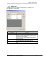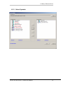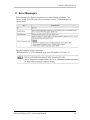
1
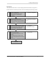
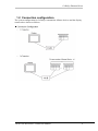
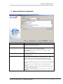
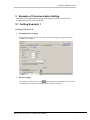
CoDeSys Ethernet Driver CoDeSys Automation Alliance CoDeSys Ethernet Driver 1 System Configuration ................................................................................................. 3 2 External Device Selection ........................................................................................... 6 3 Example of Communication Setting ........................................................................... 7 4 Setup Items................................................................................................................ 14 5 Supported Device Address ........................................................................................ 19 6 Symbol access settings .............................................................................................. 22 7 Device Code and Address Code ............................................................................... 33 8 Error Messages.......................................................................................................... 34 GP-Pro EX Device/PLC Connection Manual 1 CoDeSys Ethernet Driver Introduction This manual describes how to connect display and the External Device (target PLC). In this manual, the connection procedure will be described by the following sections: 1 System Configuration This section shows the types of external devices which can be connected ”1 System Configuration” 2 Selection of External Device Select a model (series) of external to be connected and connection method ”2 Selection of External Example of Communication Settings This section shows setting examples for communicating between the display and the external device ”3 Example of Setup Items This section describes communication setup items on the Display. Set communication settings of the Display with GP-Pro Ex or in off-line mode. ”4 Setup Items” 3 4 Device” communication settings” Operation GP-Pro EX Device/PLC Connection Manual 2 CoDeSys Ethernet Driver 1 System Configuration 1.1 Supported Device/PLC The following table lists system configurations for connecting some of CoDeSys Automation Alliance devices and the display. Series Name BOSCH Rexroth CPU Link I/F Indra Control L20 X7E Ethernet Port Indra Control L40 X7E Ethernet Port Communication I/F Comment Setting Example Level4 / Level2 (Route) Example 1 Example 2 Example 4 Indra Control PPC-R22 Ethernet Port WAGO I/O System 750841 Ethernet Port ELAU PACDrive C200 Ethernet Port Port 5000 Level4 Windows NT Ethernet Port Level4 / Level2 (Route) Example 1 Example 2 Example 4 CombiControl C5 Ethernet Port Level2 Example 3 MX213 ETH1 / ETH2 Level2 (Route) Example 5 Level4 Ethernet Port 3S SoftPLC KEB Bachmann MX200 Series GP-Pro EX Device/PLC Connection Manual Example 1 Example 2 3 CoDeSys Ethernet Driver 1.2 Connection configuration The system configuration for CoDeSys Automation Alliance devices and the display connected are shown as follows. GP-Pro EX Device/PLC Connection Manual 4 CoDeSys Ethernet Driver NOTE The number of connectable Displays depends on the External device. Please refer to the manual of External device for more details. GP-Pro EX Device/PLC Connection Manual 5 CoDeSys Ethernet Driver 2 External Device Selection Select the External Device to be connected to the Display. Setup Items Manufacturer Setup Description Select the maker of the External Device to be connected. Select "CoDeSys Automation Alliance" Series Select a model (series) of the External Device to be connected and connection method. Select "CoDeSys Ethernet". Check the External Device which can be connected in system configuration. “System Configuration” Select the Display port to be connected to the External Device. (Select Ethernet) Check this option when you synchronize the system data area of the Display and the device (memory) of the External Device. When synchronized, you can use the ladder program of the External Device to switch the display or display the window on the Display. Port Use System Area Cf. GP-Pro EX Reference Manual "LS Area (Direct Access Method Area)" This can be also set with GP-Pro EX or in off-line mode of the Display. Cf. GP-Pro EX Reference Manual "System Settings [Display Unit] [System Area] Settings Guide" Cf. Maintenance/Troubleshooting Guide "Main Unit - System Area Settings" GP-Pro EX Device/PLC Connection Manual 6 CoDeSys Ethernet Driver 3 Example of Communication Setting Examples of communication settings of the display and the external device recommended by Pro-face are shown. 3.1 Setting Example 1 Setting of GP-Pro EX Communication Settings To display the setting screen, select [Device/PLC Settings] from [System setting window] in workspace. Device Settings ([Setting]) of the External Device you want To display the setting screen, click to set from [Device-Specific Settings] of [Device/PLC Settings]. GP-Pro EX Device/PLC Connection Manual 7 CoDeSys Ethernet Driver Setting of External Device Please refer to CoDeSys software and/or external Device user manual for more details about how to setup IP Address and port of External Device. Notes - Check with a network administrator about IP address. Do not set the duplicate IP address. Set IP address on the external device for IP address in the Device-Specific settings. You need to set IP address on the display in the off-line mode of the display. GP-Pro EX Device/PLC Connection Manual 8 CoDeSys Ethernet Driver 3.2 Setting Example 2 Setting of GP-Pro EX Communication Settings Please refer to example 1. Device Settings To display the setting screen, click ([Setting]) of the External Device you want to set from [Device-Specific Settings] of [Device/PLC Settings]. Setting of External Device Please refer to CoDeSys software and/or external Device user manual for more details about how to setup IP Address and port of External Device. Please refer to chapter 6 for the details of symbol access settings. Notes - Check with a network administrator about IP address. Do not set the duplicate IP address. Set IP address on the external device for IP address in the Device-Specific settings. You need to set IP address on the display in the off-line mode of the display. GP-Pro EX Device/PLC Connection Manual 9 CoDeSys Ethernet Driver 3.3 Setting Example 3 Setting of GP-Pro EX Communication Settings Please refer to example 1. Device Settings To display the setting screen, click ([Setting]) of the External Device you want to set from [Device-Specific Settings] of [Device/PLC Settings]. Setting of External Device Please refer to CoDeSys software and/or external Device user manual for more details about how to setup IP Address and port of External Device. Please refer to chapter 6 for the details of symbol access settings. Please make sure that “Yes” is selected for [Motorola Byteorder]. Notes - Check with a network administrator about IP address. Do not set the duplicate IP address. Set IP address on the external device for IP address in the Device-Specific settings. You need to set IP address on the display in the off-line mode of the display. GP-Pro EX Device/PLC Connection Manual 10 CoDeSys Ethernet Driver 3.4 Setting Example 4 Setting of GP-Pro EX Communication Settings To display the setting screen, select [Device/PLC Settings] from [System setting window] in workspace. Please make sure that [Source ID] is set to a value which is not used by [Target ID] of any of connected PLCs. GP-Pro EX Device/PLC Connection Manual 11 CoDeSys Ethernet Driver Device Settings To display the setting screen, click ([Setting]) of the External Device you want to set from [Device-Specific Settings] of [Device/PLC Settings]. Setting of External Device Please refer to CoDeSys software and/or external Device user manual for more details about how to setup IP Address, port and target ID of External Device. Please refer to chapter 6 for the details of symbol access settings. Notes - Check with a network administrator about IP address. Do not set the duplicate IP address. Set IP address on the external device for IP address in the Device-Specific settings. You need to set IP address on the display in the off-line mode of the display. GP-Pro EX Device/PLC Connection Manual 12 CoDeSys Ethernet Driver 3.5 Setting Example 5 Setting of GP-Pro EX Communication Settings Please refer to example 4. Device Settings To display the setting screen, click ([Setting]) of the External Device you want to set from [Device-Specific Settings] of [Device/PLC Settings]. Setting of External Device Use Bachmann M-PLC and Solution Center for communication setting. Please refer to CoDeSys software and/or external Device user manual for more details about how to setup IP Address and port of External Device. 1. Use M-PLC to create a new project where symbol addresses and programs are defined and download it to the PLC 2. Use Solution Center to activate [ARTISrvPort] of the downloaded M-PLC project and a port number to it. [ModuleIndex] of the M-PLC project displayed in Solution Center must correspond with [Target ID]. 3. If there are multiple M-PLC projects downloaded to the PLC, each M-PLC project needs to have its own [ARTISrvPort] and [ModuleIndex]. GP-Pro EX can configure only one M-PLC project per node. Please add as many PLCs as the number of M-PLC projects in [Communication Settings] and set [Port] and [Target ID] in [Individual Device Settings] dialog respectively. Notes - Check with a network administrator about IP address. Do not set the duplicate IP address. Set IP address on the external device for IP address in the Device-Specific settings. You need to set IP address on the display in the off-line mode of the display. GP-Pro EX Device/PLC Connection Manual 13 CoDeSys Ethernet Driver 4 Setup Items 4.1 Setup Items in GP-Pro EX 4.1.1 Communication Settings To Display the setting screen, select [Device/PLC Settings] from [System setting window] in workspace. Setup Items Port No. Timeout Retry Wait to Send Source ID Setup Description Use an integer from 1024 to 65535 to enter the port number of the Display. When you check the option of [Auto Assign], the port number will be automatically set. Use an integer from 1 to 127 to enter the time (s) for which the Display waits for the response from the External Device. If there is no response from the External Device, use an integer from 0 to 255 to enter how many times the Display retransmits the command. Use an integer from 0 to 255 to enter the amount of standby time (ms) the Display counts from the time it receives a packet to the time it transmits the next packet. Use an integer from 0 to 4294967295. This setting parameter is used only with relation to PLCs with level 2 route protocol configured via [Individual Device Settings] GP-Pro EX Device/PLC Connection Manual 14 CoDeSys Ethernet Driver 4.1.2 Device Setting (Access = Direct Address) ([Setting]) of the External Device you To display the setting screen, click want to set from [Device-Specific Settings] of [Device/PLC Settings]. [DeviceWhen connecting multiple External Devices, you can click from Specific Settings] of [Device/PLC Settings] to add the External Device which is available to set. Setup Items Access IP Address Port Channel (Protocol) Target ID Motorola Byteorder GP-Pro EX Device/PLC Connection Manual Description Select either [Direct Address] or [Symbol Address] Set IP Address of the External Device Set Ethernet port of the External Device Select the communication protocol that the PLC supports among [Level4] [Level2] [Level2 Route] Set the target ID of the PLC or an application unit within the PLC. Only relevant if the PLC uses [Level2] protocol. Select Motorola Byteorder of the External Device 15 CoDeSys Ethernet Driver 4.1.3 Device Setting (Access = Symbol Address) When “3S CoDeSys Symbol” type is selected as Series, Symbol File, “New”, “Import” & “Edit” buttons are displayed. Setup Items Symbol File NOTE: No symbol file is available for a newly created project. Symbol files can be added via [New] or [Import]. Creates an empty symbol file and opens [Symbol List] dialog. (See 6.3.2 ) Opens [Select Symbols] dialog. (See 6.3.3 ) Opens [Symbol List] dialog with loading the currently selected symbol file (See 6.3.2 ) New Import Edit NOTE Description Select the symbol file to be used for the PLC. Please make sure the above settings match with “Online – Communication Parameters” of Device/PLC programming software, otherwise communication error will occur. GP-Pro EX Device/PLC Connection Manual 16 CoDeSys Ethernet Driver 4.2 Settings in Off-Line Mode Setup Items Port No Timeout(s) Retry Wait To Send (ms) Source ID Description Set the Port No. of the Display. Select either [Fixed] or [Auto]. When you select [Fixed], use an integer from 1024 to 65535 to enter the port No. of the Display. When you select [Auto], the port No. will be automatically assigned regardless of the entered value. Use an integer from 1 to 127 to enter the time (s) for which the Display waits for the response from the External Device. In case of no response from the External Device, use an integer from 0 to 255 to enter how many times the Display retransmits the command. Use an integer from 0 to 255 to enter standby time (ms) for the Display from receiving packets to transmitting next commands. Display the source ID. It is used only with relation to PLCs with level 2 route protocol configured via [Individual Device Settings] GP-Pro EX Device/PLC Connection Manual 17 CoDeSys Ethernet Driver Setup Items Access IP Address Port Channel (Protocol) Target ID Motorola Byteorder GP-Pro EX Device/PLC Connection Manual Description Display the selected access method. The value is either [Direct Address] or [Symbol Address]. Set IP Address of the External Device Set Ethernet port of the External Device Select the communication protocol that the PLC supports among [Level4] [Level2] [Level2 Route] Display the target ID of the PLC or an application unit within the PLC. Only relevant if the PLC uses [Level2] protocol. Select Motorola Byteorder of the External Device 18 CoDeSys Ethernet Driver 5 Supported Device Address 5.1 Direct Access The following table shows the range of supported device addresses in direct access. This address can be specified as system data area. Device Input Output Marker Bit Address %IX00000.00 ~ %IX65535.15 %QX00000.00 ~ %QX65535.15 %MX00000.00 ~ %MX65535.15 GP-Pro EX Device/PLC Connection Manual Word Address %IW00000 ~ %IW65535 %QW00000 ~ %QW65535 %MW00000 ~ %MW65535 32bits L/H 19 CoDeSys Ethernet Driver 5.2 Symbol Access The following table shows the range of supported device addresses in symbol access. This address can be specified as system data area. Device BOOL BYTE SINT USINT INT UINT WORD ENUM DINT DWORD UDINT DATE DT POINTER REAL TIME TOD LWORD LINT ULINT LREAL Bit Address Single 1D Array 2D Array 3D Array Single 1D Array 2D Array 3D Array Single 1D Array 2D Array 3D Array Single 1D Array 2D Array 3D Array Single 1D Array 2D Array 3D Array Single 1D Array 2D Array 3D Array Single 1D Array 2D Array 3D Array Single 1D Array 2D Array 3D Array <SYMNAME> <SYMNAME>[xl] ~ <SYMNAME>[xh] <SYMNAME>[xl,yl] ~ <SYMNAME>[xh,yh] <SYMNAME>[xl,yl,zl] ~ <SYMNAME>[xh,yh,zh] <SYMNAME>.00 ~ <SYMNAME>.07 <SYMNAME>[xl].00 ~ <SYMNAME>[xh].07 <SYMNAME>[xl,yl].00 ~ <SYMNAME>[xh,yh].07 <SYMNAME>[xl,yl,zl].00 ~ <SYMNAME>[xh,yh,zh].07 <SYMNAME>.00 ~ <SYMNAME>.15 <SYMNAME>[xl].00 ~ <SYMNAME>[xh].15 <SYMNAME>[xl,yl].00 ~ <SYMNAME>[xh,yh].15 <SYMNAME>[xl,yl,zl].00 ~ <SYMNAME>[xh,yh,zh].15 - <SYMNAME>.00 ~ <SYMNAME>.31 <SYMNAME>[xl].00 ~ <SYMNAME>[xh].31 <SYMNAME>[xl,yl].00 ~ <SYMNAME>[xh,yh].31 <SYMNAME>[xl,yl,zl].00 ~ <SYMNAME>[xh,yh,zh].31 - <SYMNAME>.00 ~ <SYMNAME>.31 <SYMNAME>[xl].00 ~ <SYMNAME>[xh].31 <SYMNAME>[xl,yl].00 ~ <SYMNAME>[xh,yh].31 <SYMNAME>[xl,yl,zl].00 ~ <SYMNAME>[xh,yh,zh].31 - Word Address 32 Bits Remarks - - *1 *6 L/H *1 *2 L/H *1*3 <SYMNAME> <SYMNAME>[xl] ~ <SYMNAME>[xh] <SYMNAME>[xl,yl] ~ <SYMNAME>[xh,yh] <SYMNAME>[xl,yl,zl] ~ <SYMNAME>[xh,yh,zh] <SYMNAME> <SYMNAME>[xl] ~ <SYMNAME>[xh] <SYMNAME>[xl,yl] ~ <SYMNAME>[xh,yh] <SYMNAME>[xl,yl,zl] ~ <SYMNAME>[xh,yh,zh] <SYMNAME> <SYMNAME>[xl] ~ <SYMNAME>[xh] <SYMNAME>[xl,yl] ~ <SYMNAME>[xh,yh] <SYMNAME>[xl,yl,zl] ~ <SYMNAME>[xh,yh,zh] <SYMNAME> <SYMNAME>[xl] ~ <SYMNAME>[xh] <SYMNAME>[xl,yl] ~ <SYMNAME>[xh,yh] <SYMNAME>[xl,yl,zl] ~ <SYMNAME>[xh,yh,zh] <SYMNAME> <SYMNAME>[xl] ~ <SYMNAME>[xh] <SYMNAME>[xl,yl] ~ <SYMNAME>[xh,yh] <SYMNAME>[xl,yl,zl] ~ <SYMNAME>[xh,yh,zh] <SYMNAME> <SYMNAME>[xl] ~ <SYMNAME>[xh] <SYMNAME>[xl,yl] ~ <SYMNAME>[xh,yh] <SYMNAME>[xl,yl,zl] ~ <SYMNAME>[xh,yh,zh] <SYMNAME> <SYMNAME>[xl] ~ <SYMNAME>[xh] <SYMNAME>[xl,yl] ~ <SYMNAME>[xh,yh] <SYMNAME>[xl,yl,zl] ~ <SYMNAME>[xh,yh,zh] GP-Pro EX Device/PLC Connection Manual *1 - *1 - *1 - *1*5 - *1*5 20 CoDeSys Ethernet Driver STRING Single 1D Array 2D Array 3D Array - <SYMNAME> <SYMNAME>[xl] ~ <SYMNAME>[xh] <SYMNAME>[xl,yl] ~ <SYMNAME>[xh,yh] <SYMNAME>[xl,yl,zl] ~ <SYMNAME>[xh,yh,zh] st “xl” 1 Dimension Lower Range “xh” 1 Dimension Upper Range ‘yl’ 2 Dimension Lower Range ‘yh’ 2 Dimension Upper Range ‘zl’ 3 Dimension Lower Range ‘zh’ 3 Dimension Upper Range - *1*4 Negative range not supported Lower range is ‘0’ or upper st nd Negative range not supported Lower range is ‘0’ or upper nd rd Negative range not supported Lower range is ‘0’ or upper rd *1 - <SYMNAME>: Symbol Name including structure name in case of structure. The maximum number of characters for Symbol Name is 255 including delimiters and element number. The maximum number of characters when using D-Script is limited to 54. Example: BOOL type single symbol “BOOLSYMBOL” BOOL type 1D Array “BOOL1D[10] WORD type 2D Array “WORD2D[10,10] UDINT type 3D Array “UDINT3D[0,1,2] STRING in User Defined Structure “STRUCT001.STRINGSYM” [STRUCT001] You cannot start names with any of the following text: LS, USER, SCR, PRT *2 – Handled as 8 bit devices in the External Device, but as 16-bit devices in GP-Pro EX. Upper byte is set to 0 in GP-Pro EX. *3 - By default, 16 words are used for the system data area. If you want to use less than 16 words, first you need to map an array tag greater than 16 words and define the items for the system data area. *4 - Parts for which a STRING device is set do not support the Duplicate - Automatically Increment Address feature. Specify the STRING length / 2 as offset to duplicate when ARRAY of STRING. Last character of a STRING can not be displayed / changed if STRING size is odd number of characters. *5 – Handled as 64 bit devices in the External Device, but as 32-bit devices in GP-Pro EX. Upper 32 bit information is discarded in GP-Pro EX. NOTE Please make sure at least one WORD type symbol exists in the project. GP-Pro EX Device/PLC Connection Manual 21 CoDeSys Ethernet Driver 6 Symbol access settings 6.1 Overview This chapter will first explain the steps to import symbols from PLC projects step by step, and the individual configuration dialogs for symbol access will be explained. 6.2 Step by step guide to use symbol addresses in GP-Pro EX 1) Scope This section explains the step by step procedure to import symbols from PLC Project. Note: “First Steps.pro” from sample project in CoDeSys Programming Software used here as PLC Project. 2) Prepare PLC Project a. From CoDeSys Programming environment, select menu [File] [Open] to open a PLC project. b. Select [Options] from [Project] to open [Options] dialog. c. In the dialog, select [Symbol configuration]. d. Check [Dump XML symbol table]. e. Select [Configure symbol file …] to open [Set object attributes] dialog. f. In the dialog, check [Export variables of object] for every variable list of which symbols need to be exported. g. From menu [Project] select [Rebuild All] and build the project. GP-Pro EX Device/PLC Connection Manual 22 CoDeSys Ethernet Driver 3) Prepare GP-Pro EX Project a) In GP-Pro EX, create a new project. In [Device/PLC] selection, select CoDeSys Ethernet Driver as shown below. b) From [Device-Specific Settings], select [Individual Device Settings]. c) Select [Symbolic Address] as access method. d) Click [Import] button and click again [Import] button in Symbol Selection Dialog. GP-Pro EX Device/PLC Connection Manual 23 CoDeSys Ethernet Driver 4) Import Symbols a) Select the symbol file (*.SYM_XML) saved in the PLC project by the PLC programming software. b) All the symbols are displayed in [Available Items]. GP-Pro EX Device/PLC Connection Manual 24 CoDeSys Ethernet Driver c) (copy all), or (copy checked) buttons, symbols can By clicking be copied to [Selected Items]. By clicking on the check box next to each symbol, individual symbols can be selected. Selected symbols are shown in red. d) After the selection of symbol, close the dialog with [OK] button. (Note: All symbols are selected to import in GP-Pro EX in this example.) e) If any warning or error has occurred during import, the following message will be shown so that the warning and/or error message can be saved into a log file. The log file can be viewed by a text editor such as NOTEPAD. GP-Pro EX Device/PLC Connection Manual 25 CoDeSys Ethernet Driver 5) Use Symbols in screen parts a. In Address dialog, these available symbols are displayed for use it in Screen data. Symbols irrelevant for the current screen part are grayed out. (For example, BOOL data type is not relevant for numeric displays. b. When a symbol of an array type is selected, indexes of each dimension need to be specified. GP-Pro EX Device/PLC Connection Manual 26 CoDeSys Ethernet Driver c. A user-defined data type is displayed with having its internal member elements folded. By selecting [+] sign, the member elements can be expanded. GP-Pro EX Device/PLC Connection Manual 27 CoDeSys Ethernet Driver 6.3 Description of setting dialogs 6.3.1 Individual Device Settings The symbol addresses to be used in GP-Pro EX need to be registered. Via [Individual Device Settings] a new symbol file can be created import symbols from PLC projects. Setup Items Symbol File New Import Edit Description Displays the name of the symbol file currently in use by the selected node. Creates an empty symbol list and opens it in [Symbol List] dialog. Opens [Select Symbols] dialog where more symbols can be imported into the current symbol file from another. Opens [Symbol List] dialog with the symbols currently loaded. GP-Pro EX Device/PLC Connection Manual 28 CoDeSys Ethernet Driver 6.3.2 Symbol List The following dialog can be opened via [Import] button on [Symbol List] or [Individual Device Settings] dialog. Setup Items Symbol List Name Show Import Delete Description Shows the name of the currently selected symbol file. Selects the data type of the symbol addresses to be displayed. All the symbol addresses of the type other than selected will be hidden. If “ALL” has been selected, all the symbol addresses will be displayed. Opens [Select Symbols] dialog to import additional symbol addresses into the current symbol list. Removes the selected symbol address from the symbol list. GP-Pro EX Device/PLC Connection Manual 29 CoDeSys Ethernet Driver 6.3.3 Select Symbols GP-Pro EX Device/PLC Connection Manual 30 CoDeSys Ethernet Driver Setup Items Symbol File Import Available Items Selected Items >> (Copy all) > (Copy checked items) < (Remove checked items) << (Remove all) Select All Unselect All Type Filter Option GP-Pro EX Device/PLC Connection Manual Description Displays the symbol file (*.SYM_SML) selected previously. Opens a dialog to select a symbol file (*.SYM_SML). Displays the symbols in the selected symbol file. Displays the selected symbols to be stored in GP-Pro EX. Adds all the displayed symbols to the list of selected items. Adds only the checked symbols to the list of selected items. Removes only the checked symbols from the list of selected items. Removes all the symbols from the list of selected items. Sets checks to all the displayed symbols. Removes the checks from all the displayed symbols. Opens [Type Filter] dialog to configure the symbol type filter. ( See 6.3.4 ) When large amount of symbols are used in PLC project, and only WORD symbols are needed in GPPPRO EX project, user can set the type filter to display only WORD type symbols. 31 CoDeSys Ethernet Driver 6.3.4 Type Filter Setup Items Select All Unselect All Type Show GP-Pro EX Device/PLC Connection Manual Description Sets checks to all the displayed data types. Removes the checks from all the displayed types. Data type Sets the visibility of the symbols of the data type in [Select Symbols] dialog ( see 6.3.3 ). 32 CoDeSys Ethernet Driver 7 Device Code and Address Code Use device code and address code when you select "Device Type & Address" for the address type in data displays. Device Input Output Marker NOTE Device Name %I %Q %M Device Code 0x0080 0x0081 0x0083 When [Symbol Address] is selected for [Access] the device code and address code must not be used. GP-Pro EX Device/PLC Connection Manual 33 CoDeSys Ethernet Driver 8 Error Messages Error messages are displayed on the screen of the Display as follows: "No. : Device Name: Error Message (Error Occurrence Area)". Each description is shown below. Display Examples of Error Messages “RHAA065:PLC1: TCP connection open error (IP Address: 192.168.1.1)” GP-Pro EX Device/PLC Connection Manual 34