1
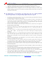
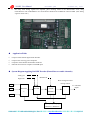
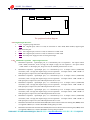
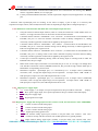
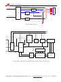
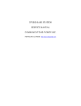
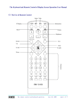
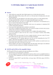
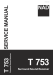
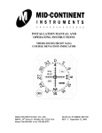
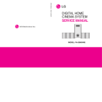
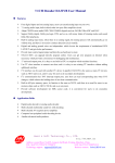
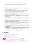
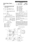
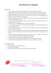
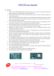
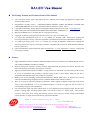
The Writing Formats and Technical Terms of This Manual ¾ ¾ ¾ ¾ ¾ ¾ ¾ ¾ ¾ User mainframe means single chip applied by user; DA32X means single chip applied by digital audio decoder of DA32 series. Requirements of Dolby means <<MULTICHANNEL DIGITAL AUDIO DECODING SYSTEM FOR CONSUMER PRODUCTS Licensee Information Manual Version 2.0 April, 1997>>. Copyrights of the Dolby, Dolby digital are belonged to Dolby Laboratories Inc. http:// www.dolby.com Dolby testing disk means DOLBY DVD DEMO AND TEST DISC VERSION 1.0 MP3 means MPEG layer 3, decoding has no a copyright restricting. Copyright of HDCK is belonged to Pacific Microsonics Inc. http://www.hdcd.com。 “n” means 4bit (hexadecimal, from “0” to “f”) variable, for example, 2nH / 0nnH means sending and receiving instructions, and any values that parameter is hexadecimal between the 20H/ 00H and 2fH/ ffH. “b” means byte (binary, from “0” to “1”) variable, for example, 0010b1bbB / 0nnH means sending and receiving instructions, and any values that parameter is hexadecimal between the 20H/ 00H and 2fH/ ffH, but C2 is fixed for 1. nnH / nnH means the general expression form of instructions (C7-C0)/parameters (P7-P0), sending and receiving are suitable. Features ¾ ¾ ¾ ¾ ¾ ¾ Apply CRYSTAL CS4926(CS49326)24bit audio DSP, CS8415 low time base error 96KHz digital receiver, and CS4228A 96K/24bit A/D & D/A CODEC. Internal analog mute function, matching CS4926 high-speed DSP processing can achieve the best mute effect automatically, and reduce noise down to minimum. Apply late-model bi-directional bus HSBⅡ of high speed, user mainframe can continuously send as many as 16 set of instructions and parameters, and then using of user is more nimble. Moreover, the bus is compatible with HSB bus of the first generation completely. Built-in main current decoding system DOLBY DIGITAL, HDCD, MP3 and so on, besides, have various surround sound decoding and playback such as DOLBY PRO-LOGIC and RO-LOGICⅡ. There is no need for upgrade to change any hardware, totally support all digital compression code stream such as AAC and MPEGⅡ so as to suit different markets. Users have to apply for the use license of corresponding company before production. One internal fiber input and three coaxial input, or seven digital input and a digital output. Provide many groups of analog input switching signals A/B/C, can switch as many as 8 analog input;6CH switches external 5.1CH input, when analog and listening mod are stereo ANA can switch analog signal without passing decoder, or output and control directly signal from M62446. Hard & Soft Technology Co., LTD. http://www.HSAV.com Address: second floor, No.199, Longyin 2nd Road, Xixiang, Shenzhen, China TEL: 86-0755-27951479 27950879 FAX: 86-0755-27950879-213 Business contact:[email protected] Technology support:[email protected] DA32HC User Manual ¾ ¾ hsavd201.pdf October 25, 2007 Matching DV37AB OSD board can realize Chinese/English OSD menu display, the instructions of user are completely compatible with vision having not OSD, can be upgraded nimbly and boundlessly. Adding only corresponding hardware, DA32HC can realize Dolby EX6.1 and others 6.1, 7.1 functions. ¾ Equipping M62446 and bass management circuit can finish complete decoding and volume control functions; requiring very short time can let products reach Dolby standard, which provides convenience for capturing the market quickly. The Requirements on The Hardware and Testing Steps That User Applying DA32HC Decoder Design Products According with Dolby Digital Attestation of Type B. 9 9 9 9 9 9 9 9 9 9 9 9 9 The following is general testing conditions: level of every channel and left-right channel balance inching are in normal position, and compression mode is closed. The setup of speaker is Config 2 (left and right channels are big speaker, the others are small speaker, and set extra bass), play Title 30, millivoltmeter is connected with left channel, modulating volume make volume reach the maximum, should can output full power (i.e. just appear distortion.), that is the minimal request of complete machine gain.(Test complete machine gain.) The same as above, modulating volume make output be 1W (about 2.83V), and this time, level is applied in the after statement as reference 0dB. Play Title 30, respectively test central output, right channel output, left back channel output, right back channel output, the output change relative to reference 0dB can not exceed + 0.5 dB range till 0.5 dB. (Test channel balance.) Play respectively Title 43、45, respectively test left channel output, right channel output, entire time inner in playing(20Hz - 20KHz), the output change can not exceed +0.5dB range till -1dB.(Test frequency responding.) Play respectively Title 44、46、47, about between the 30 seconds and 59 seconds, respectively test central output, left back output, right back output, the output change can not exceed +0.5dB range till -1dB. (Because setup is small speaker, in the first 30 seconds, output level is able to rise slowly). (Test frequency responding.) Play Title 80, using millivoltmeter with CCIR/ARM to test all channels should lower 65dB than reference 0dB at least. (Test digital signal-to-noise ratio.) If extra bass channel has not a power amplifier, when the first 2seconds in playing Title 48, testing extra bass output should lower 24dB +/-3dB than reference 0 dB. If extra bass channel has a power amplifier or pure decoding, extra bass output should higher 15dB than reference 0dB. (Test bass channel balance.) Play Title 48, in the first 2seconds, extra bass is closed, testing extra bass should lower 50dB reference 0dB. (Test bass muting switch.) Play Title 48, in the first 2seconds, testing left channel output should higher 5.5dB than reference 0dB. (Test bass management level balance.) Play Title 72, make tone bass reach the maximum, if using oscilloscope or distortion device test left channel output, the slight distortion is acceptable, but playing Title 73 shouldn’t distort. (Test bass surcharge.) Speakers are configured for Config 1 (all speakers are small, and have extra bass); left speaker and right speaker should lower 50dB than reference 0dB at least. (Test bass management switch.) Input 1KHz / 200mV analog signal from every analog port, under the BYPASS state, output of left channel and right channel relative to reference 0dB can not exceed +1dB range till –1dB. (Test analog input.) © 2002-2009 Hard & Soft Technology Co., LTD. http://www.HSAV.com Page 2 of 7 DA32HC User Manual 9 9 9 9 9 hsavd201.pdf October 25, 2007 Do away with analog signal have inputted, place listening mode in the PRO-LOGIC state, using millivoltmeter with CCIR/ARM to test all channels should lower 65dB than reference 0dB. (Test analog signal-to-noise ratio.) Application Fields Compose multi-format digital audio decoder. Compose AV receiving power amplifier. Computer multi-channel multimedia sound box. External sound card of computer with USB input. System Diagram Applying DA32HC Decoder (Dotted lines are audio channels) Analog IN Karaoke IN Digital IN VFD KEY Mainfram e DA32X Electronic volume (M62446) Bass management and muting control 5.1 CH audio output Remote EQ frequency sampling (BA3834、MSG05A) © 2002-2009 Hard & Soft Technology Co., LTD. http://www.HSAV.com Page 3 of 7 DA32HC User Manual DA32HC Connection Methods CN1 hsavd201.pdf CN2 October 25, 2007 CN3 C N 6 CN4 CN5 The peripheral sockets diagram CN1. Digital Input Interface: 1. GND Digital input ground wire. 2. RX1 Set 1 digital input, when it is used, its instruction is 34H / 80H; When default, digital signal inputs from this port. 3. RX2 Set 2 digital input, when it is used, its instruction is 34H / 81H. 4. RX3 Set 3 digital input, when it is used, its instruction is 34H / 82H. 5. +5V Provide power supply for fiber receiving head input. CN2。Mainframe expansion input/output interface: 1. Mainframe expansion input/output port, it is controlled by bit 0 of expansion I/O output control (57H / 0nnH) instruction, if bit 0 is high, the output is high; can use expansion I/O input control (58H / 0nnH)to find input port; If input is low, the callback parameter bit 0 is low. 2. Mainframe expansion input/output port, it is controlled by bit 7 of output control (57H/0nnH) instruction, if bit 7 is high, the output is high; can use expansion I/O input control(58H / 0nnH)to find input port; If input is low, the callback parameter bit 7 is low. 3. Mainframe expansion input/output port, it is controlled by bit 6 of output control (57H/0nnH) instruction, if bit 6 is high, the output is high; can use expansion I/O input control(58H / 0nnH)to find input port; If input is low, the callback parameter bit 6 is low. 4. Mainframe expansion input/output port, it is controlled by bit 5 of output control (57H/0nnH) instruction, if bit 5 is high, the output is high; can use expansion I/O input control(58H / 0nnH)to find input port; If input is low, the callback parameter bit 5 is low. 5. Mainframe expansion input/output port, it is controlled by bit 4 of output control (57H/0nnH) instruction, if bit 4 is high, the output is high; can use expansion I/O input control(58H / 0nnH)to find input port; If input is low, the callback parameter bit 4 is low. 6. Mainframe expansion input/output port, it is controlled by bit 3 of output control (57H/0nnH) instruction, if bit 3 is high, the output is high; can use expansion I/O input control(58H / 0nnH)to find input port; If input is low, the callback parameter bit 3 is low. 7. Mainframe and DA32X communication HSB (three lines bi-directional time-sharing bus) BCK, when it is applied as RS232, it is used as DA32HC sending data port TxD. 8. Mainframe and DA32X communication HSB (three lines bi-directional time-sharing bus) SDA, when it is applied as RS232, it is used as DA32HC receiving data port RxD. © 2002-2009 Hard & Soft Technology Co., LTD. http://www.HSAV.com Page 4 of 7 DA32HC User Manual hsavd201.pdf October 25, 2007 9. Mainframe and DA32X communication HSB (three lines bi-directional time-sharing bus) HOLD, when it is applied as RS232, it is an empty pin. 10. Used by mainframe RESET DA32EC, normal requirement is high level (usual application is an empty pin). * Attention: when input/output ports are working, if user wants to employ a port as input, it is necessary that expansion I/O input control (57H / 0nnH) instruction make corresponding bit high. (Have configured pull-ups.) CN3. Mainframe communication and Main unit control input/output interface: 1. 6CH_IN external 6-channel input selection, when it is used, the instruction is 34H / 0a0H, when it is effective, it is high; external circuit can be used to switch external 6-channel. 2. 6-channel volume control IC(M62446FP) P41(CLOCK), if software does not use M62446 in the DA32HC, this pin is a extra bass channel commixture switch of Dolby configuration 2 , adding necessarily a audion opposition of PNP can be applied by the original circuit. 3. 6-channel volume control IC(M62446FP) P41(DATA), if software does not use M62446 in the DA32HC, this pin is a extra bass channel muting switch, adding necessarily a audion opposition of PNP can be applied by the original circuit. 4. 6-channel volume control IC(M62446FP)P39(LATCH), if software does not use M62446 in the DA32HC, this pin is a muting switch of the others channels excepting extra bass channel, adding necessarily a audion opposition of PNP can be applied by the original circuit. 5. Control port of Decoder outputting directly, under the analog input or listening mode is under the BYPASS state, this pin is high. 6. Mike switch control input, when MIC is not inserted, this pin is low, or it is high; even though have sent “karaoke commixture switch (7eH/20H)”instruction, this pin must be high, and the fourth pin of M62446 has corresponding control action. 7. Mainframe expansion input/output port, it is controlled by bit 1 of output control (57H/0nnH) instruction, if bit 1 is high, the output is high; can use expansion I/O input control(58H / 0nnH)to find input port; If input is low, the callback parameter bit 1 is low. 8. Mainframe expansion input/output port, it is controlled by bit 0 of output control (57H/0nnH) instruction, if bit 0 is high, the output is high; can use expansion I/O input control(58H / 0nnH)to find input port; If input is low, the callback parameter bit 0 is low. CN4。Digital power supply input: 1. +3V Power supply +3.3V output, if no special requirement, this pin could be connected emptily. 2. VDD HCU power supply input, if no special requirement, this pin could be connected emptily. 3. +5V DSP power supply input. 4. GND Digital ground wire input. CN5. Digital power supply and analog input interface (when it is used, the instruction is 33H / 100bbb00B): 1. SC Control 3 used to extend analog input. 2. SB Control 2 used to extend analog input. 3. SA Control 1 used to extend analog input. 4. GND Signal input analog ground wire. 5. LIN Left channel analog signal input (contains a low-pass filter; first connects with 150Ω resistance serially, and then connects with 1500P capacitance to ground parallel). 6. RIN Right channel analog signal input (contains a low-pass filter; first connects with 150Ω © 2002-2009 Hard & Soft Technology Co., LTD. http://www.HSAV.com Page 5 of 7 DA32HC User Manual 7. 8. hsavd201.pdf October 25, 2007 resistance serially, and then connects with 1500P capacitance to ground parallel). –9V Analog signal power input. +9V Analog signal power input. CN6. Analog signal output interface: 1. SW Extra bass channel signal output. 2. C Central channel signal output. 3. RS Back right channel signal output. 4. GND Analog ground wire output. 5. LS Back left channel signal output. 6. R Right channel signal output. 7. L Left channel signal output. 8. –9V Analog signal power supply input. 9. +9V Analog signal power supply input. Electrical Specification Item Digital power supply +5V Digital operating current Analog circuit voltage analog input level(@-20dB) Analog input impedance analog output (L&R @ 0dB) analog output(LS&RS&C&ER&ELSW @ 0dB) Output noise level (digital input CCIR/ARM) output noise level (digital input,not weighted) Output noise level (analog input CCIR/ARM) output noise level (digital input,not weighted) Output impedance Digital input Minimum 4.75V 500mA +9V / -9V 200mV 2.0Vrms 2.8Vrms 50uV 560uV 70uV 600uV Normal +5V 600mA +12V / -12V 210mV 100 Ohm 2.2Vrms 3.0Vrms 58uV(S/N = 93dB) 600uV 76uV(S/N = 90dB) 700uV 100ohm 0.5Vp-p Maximum 5.15V 750mA +18V / -18V 220mV 2.3Vrms 3.3Vrms 76uV 800uV 80uV 800uV Instructions of The Power Supply and Ground Wire In DA32HC, digital ground wire have connected with analog ground wire, when the mainboard LAYOUT, user should pay attention to the digital and analog power supply and ground wire. Input and output of the analog ground wire and digital ground wire are connected in the DA32HC, so anywhere out of decoder board is no connection, or can appear low frequency noise. DGND, AGND, and corresponding parts shouldn’t have any electrical connection. +/-9V stable voltage may be +/-9V range till +/-18V. Filament voltage and VEE (-28V stable voltage) are parts supplying electricity for VFD, must be revised according to different display. © 2002-2009 Hard & Soft Technology Co., LTD. http://www.HSAV.com Page 6 of 7 DA32HC User Manual hsavd201.pdf October 25, 2007 1CN1 灯丝电压(5V/200mA) FA1 FA2 VEE +5V DGND AGND -9V +9V 220V AC输入 30mA -28V稳压 700mA 变压器 +5V稳压 8 7 6 5 4 3 2 1 H8 功放及其他供电输出 50mA +/-9V稳压 Power supply diagram +9V +9V -9V -9V 6CH 8CH analog input and select GND through-pass M62446 Low-pass Power Amplifier M62429 IN1 Input IN2 Analog output selection Analog input DA32KY GND +9V -9V GND +/-9V Stable voltage AGND +5V +5V GND Stable DGND G V V N E C D E C Power amplifier Transformer rectifier voltage Power supply and ground wire diagram (Heavy lines express ground wire) © 2002-2009 Hard & Soft Technology Co., LTD. http://www.HSAV.com Page 7 of 7