1
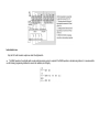
PLC Editor Overview
PLC(Programmable Logic Controller)is an electronic system with digital calculation operation, which is designed for applications in an
industrial environment.
It reads external input state signals of keys, sensors, switches, and pulse waves. Based on these input signal states or values and the
internal storage pre-prepared program, the logic, sequence, timing, counting and arithmetic operations are implemented by micro-processor, then
producing corresponding output signals, such as: switching relay, and controlling machinery equipment operation. The settings of the program and
monitor device can be easily edited and modified by using computer or program editors, to maintain the on-site program or to debug.
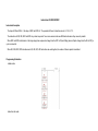
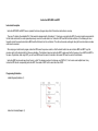
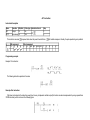
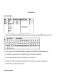
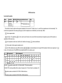
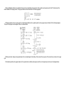
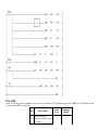
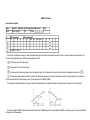
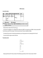
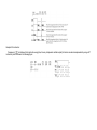
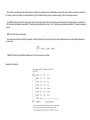
Ladder programming:
Based on the model of relay control system, PLC ladder diagram programming method uses the electrical theory and adopts the components used
in the designation similar to the time electrical device, such as button X, intermediate relay M, time relay T, counter C, contact points, and
etc..
Illustration:
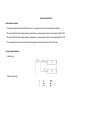
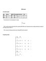
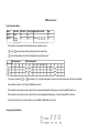
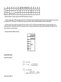
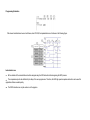
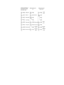
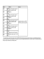
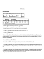
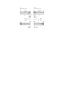
Instruction list programming:
The instruction list program editor is a text editor. All logic and calculations are inputted using instruction and operand. Based on the
functional instructions completed and the associated soft components in operand, the value of soft component is read, and logic processing and
the value of soft components are written.
Illustration:
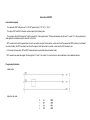
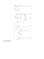
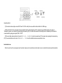
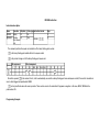
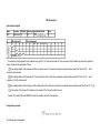
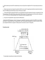
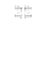
Program conversion:
These two programming languages mentioned above are interchangeable based on user's preference or the practicability of the controlling
environment. Users can choose the most appropriate programming language.
Illustration:
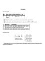
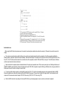
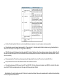
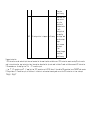
Outline
This section briefly describes the use of PLC programming software to write a simple PLC control program and programming operations,to help
beginners become familiar with and master the programming software operation.The following is the PLC development steps
The first step:Start programming software, enter the program window.
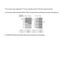
Step Two:Point "New" pop-up "New Project" window, set the "PLC Series", "PLC Type" and "programming language."
Step Three:In the "Project Management" area, click the "Programs" to start writing the ladder program.
Step Four:Add instruction.
Step Five:Save the program.
Step Six:Compile.
Step Seven:Communication with the PLC.
Step Eight:Write to the PLC
Step Nine:Start PLC (RUN state)
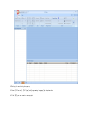
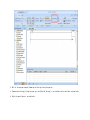
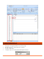
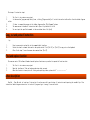
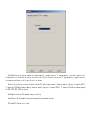
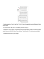
Start the software
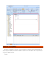
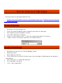
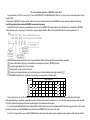
PLC properly installed, click the Windows Start menu of programming - PLC Editor Programming Software,Start the PLC programming software,
programming into the main screen, the main screen as shown below:
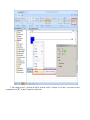
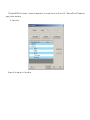
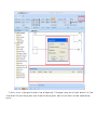
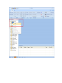
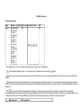
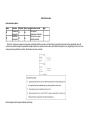
Create Project
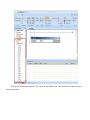
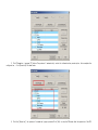
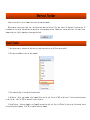
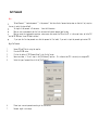
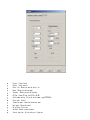
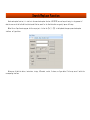
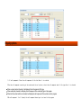
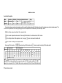
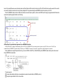
Start programming environment, you first need to create a new project.Click "New"---"New project" and the following dialogue will be
displayed, select or create a new project:
PLC Series
PLC Type
Program Language
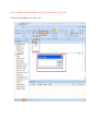
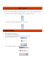
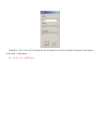
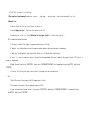
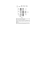
Please create a new project as shown figure instructions
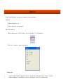
1.Move the mouse to the top left corner of the program,Click [File] menu
2.After clicking [File] menu , a new module will be displayed
3.Click [New] , and click to enter
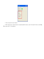
4.Waiting for new dialog box pop up
5.Select [PLC series], [PLC Type] and [programming language] by drop-down box
6.Click [OK],you can create a new project
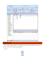
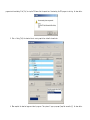
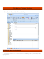
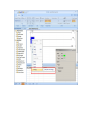
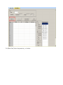
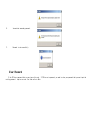
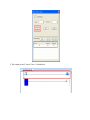
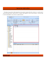
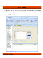
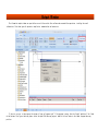
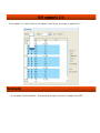
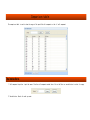
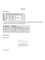
In the example, we chose LX2N type PLC,use ladder as a program language,after complete the new project ,as shown below:
Specific project management functions, see the relevant chapters.
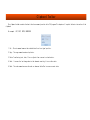
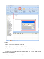
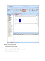
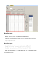
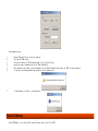
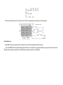
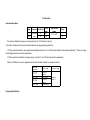
Add instructions
Method
1.Create a new project has been completed
2.Open the [Project Property] (Home panel on the left)
3.Expand [Project Property] directory tree
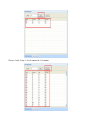
4.After expanding [Project Property],expand [Instructions]
5.Expand [Basic Sequence]
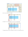
6.Use the left mouse button, select the specified sequence instructions, such as [LD]
7.Press and hold the mouse button down,Select [LD], drag to the right [Ladder (write)] input box,Placed in the specified location,
release the mouse button
8.Note: Some instructions have been added in addition to the default parameters, the input and output is empty, the user must input
parameters or component address
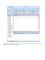
9.To add more commands, repeat the above operation until all instructions is added.
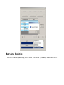
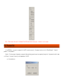
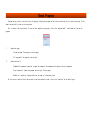
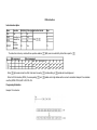
Compile Program
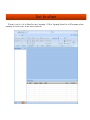
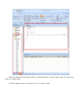
After completing the programming,then the project needs to be compiled and save.Through [F4] on the keyboard or program panel [Compile]
button to achieve program compilation compiled, as follows:
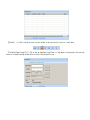
Successful compilation will have the following tips:
All errors are displayed in the list box,users can select the specified error message,Double-click the left mouse button to specify the
information, the system will automatically navigate to the location of the error or warning, to facilitate user debugger.
Note:The program only in the case of a successful compilation or no error can be downloaded to the PLC
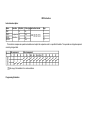
Communication test (connection with a PLC)
The main purpose of communications test is to improve the stability between the PLC and the PC, avoid lossing data of transmission.
Preparatory steps:
1. Open Run PLC Editor
2. Move the mouse on the top of the panel program modules [Online]
3. Move the mouse on the [Transfer Setup] button, left-click the button
As shown below:
4. Wait for the program response [Communication Settings] dialog box pops up
5. [Communication Settings] dialog box pops up,In the [Detailed Settings] is not checked selection box,Panel as shown below
6. Select the specified port, as shown below
7. Select the [Detailed Settings] selection box will pop up detailed design window.Panel as follows:
8.The data can be set according to their needs
Note: The communication time is set within the range of 0 to 9999, the number of retry is set within the range of 0 to 5, do not exceed
limits
9. Users complete the setup, you can click [Communication test] or [OK] button to connect the test.
10. If the test connection fails, the system will give corresponding prompt, as shown below
11. The connection is successful, as shown below
Write to PLC
Needs to be done before downloading:
1. Open Compiler.
2. Create a new project, and make this project successful compilation.
3. Installed the corresponding PLC driver on PC side,connect between PLC and PC.
4.The communication settings.
Start download.
1. After the completion of preparatory work, move the mouse to the [Online] module,Click [Write to PLC] button to open the download
settings window, as shown below:
2. Online operating window as shown below
3. Click [Parameters + program (P)] button,The system will automatically select the information box preset option, after complete the
configuration , click [Executive].As shown below:
4. Click the [Executive], the system will automatically pop up window.Click [Yes] to stop the PLC means that the operation of the PLC
program start downloading.Click [Yes] to stop the PLC means that the operation of downloading the PLC program is starting. As shown below:
5. After clicking [Yes] the download starts running compilation window.As shown below:
6. When complete the download progress window's progress. The system will pop up a prompt [compiled successfully], As shown below:
Program Simulation
Through [online simulation] function the program, can be very convenient to carry on the work done.
Preparation:
1. Enables the compiler to run
2. Prepara of a new project, and then compile
Start online simulation
1. Move the mouse pointer to the [debug] module, left-click [Analog Start / Stop}.As shown below:
2. After step 1, a new dialog box will pop up
3.Do not operate the new dialog box
4.Move the mouse pointer to the desired position to operate the analog instruction,Right-click the specified location, select [Debug] [Modify current value].As shown below:
5. After completing step 4, a new dialog box [modify the device value] will be pop up. At this point, given the device inputs
corresponding action [ON], the specific operation as shown below:
6. After completing step 5, there will be as follows
PLC menu bar
PLC Editor provides a complete and powerful functions.The menu bar is as bellow.
Introduction of integral structure
After the software start , the main interface will be show as the below figures:
The follow is the introduction of each module.
Click [File] button in the top left corner to choose these functions that include "New Project"┷"Open Project"┷"Save Project"┷"Save as
engineering" and "Print".
Strip area at the right of [File] button is [QuickAccessBar]. Keep the cursor on the button for 1 second. The fuction of the button will be
shown automatically.
The figure is [Menu toolbar].It become convenient to users for various operation. Specific operation can be seen as the below instructions.
The left side of soft panel is [Engineering management panel] .Engineering management panel show the entire project through the tree.The
project include organization structure, project name, program block, device annotation, parameter;all kinds of instruction table and so on.Users
can control the whole project by [Engineering management panel]. And [Engineering management panel] Supports the use of right button function.As
the below:
[User area] : In short,it is developed module.User can write programs and configure the Plc in the moduleコand so on.User can delete, change,
find the plc by the moudle.
[Ouput window] : The window shows all information of the current construction. It shows all the error messages.User can select the specified
message about automatic positioning and the designated area.
[Status Bar] : It is Used to display the status of current software.So that users know the situation in a timely manner.
[Find/replace Windows] through [Ctrl] + [F4] to open the window.Under project there is a large amount of code,according to that user enter
instruction to automatic matching engineering.Thus to quickly locked the specified item.
Shortcut Toolbar
A menu is consisted of a set of submenus that contain the complete commands.
When the mouse is hovering on a menu item, a brief description about the function of this menu item will be displayed in the status bar. All
the submenus will be further explained about the application in the subsequent sections. Submenus are listed as below (note: the items of these
submenus might vary slightly depending on the program functions).
Custom Toolbar
1. Users can more easily customize the functionality as what they need by using the [Quick custom toolbar] .
2. After open the combobox, select the [more command] .
3. After completing Step 2, then open the [custom] window .
4. Add Shortcut : Select a any command in the [command] box on the left side. Then click [Add] so that you will find the selected item moves
to the right box . And click [OK] can successfully add a custom tool .
5. Delete Shortcut : Select any command in the [command] box where the right side. Then click [Delete] so that you can find selected items in
the right dialog box disappears .Click [OK] to complete delete the command .
Clipboard Toolbar
The clipboard toolbar contains the basic functions commonly used to edit a PLC program.This chapter will explain the basic instruction of the
clipboard.
For example : CUT, COPY, PASTE, UNDO/REDO
1. Cut : The cut command removes the selected data from its original position .
2. Copy : The copy command creates a duplicate .
3. Paste: Transferring text, data, files or objects from a source to a destination .
4. Undo : It erases the last change done to the document reverting it to an older state .
5. Redo : The redo command reverses the undo or advances the buffer to a more current state.
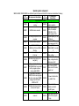
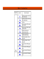
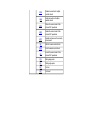
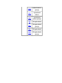
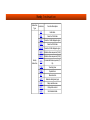
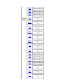
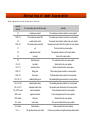
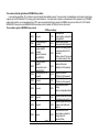
Ladder-Chart Toolbar
The ladder-chart toolbar contains the functions commonly used to edit ladder-charts.
As illustrated below :
Icon
Instruction
LD AND
OR
LDI ANI
ORI
OUT
LDP ANP
LDF ANF
ORP
ORF
INV
Function
Shortcut
Open contact
F5
Open branch
SHIFT+F5
Close contact
F6
Close branch
SHIFT+F6
Output coil
F7
Input application
F8
instruction
Draw horizontal
F9
line
Draw vertical line
F11
Delete horizontal
CTRL+F9
line
Delete vertical line CTRL+F11
Rising pluse
SHIFT+F7
Falling pluse
SHIFT+F8
Rising pluse open
CTRL+ALT+F7
branch
Falling pluse close
CTRL+ALT+F8
branch
Reverse operation
CTRL+ALT+F11
resoults
Edit Comment or Statement
In order to increase readability, this software allows user to add network comments for the codes in the current network.
Note : Win7 need administrator privileges to run
As figure below , Enter edit mode :
Specific edit mode
Edit comment
1. Prerequisite : create a new project , write at least one piece of code.
2. Click [comment] button, you are enter the edit mode when the button color darker.
3. If the button is not changed , then save the current project and rerun the software with administrator privileges .
4. After successfully into the edit comment mode, Move mouse to the user specified code , Next, It can pop-up [comment edit] window when
you double-left click on the target area .
5. At this time you can input specified comment to [comment edit] window .
6. Note: Comments only can display 27 characters maximum , After the download, display 16 characters maximum.
7. After edit the comments, click [sure] to save.
Edit statement
Prerequisite : create a new project , write at least one piece of code .
Click [statement] button, you are enter the edit mode when the button color darker.
If the button is not change , then save the current project and rerun the software with administrator privileges .
After successfully into the edit statement mode, Move mouse to the user specified code , Next, It can pop-up [statement input] window
when you double-left click on the target area .
At this time you can input specified statement to [statement input] window .
Note: The statement can not be downloaded into the PLC, the declared input is no word limit.
After editing the statement, click [sure] to save.
Program Compile
This chapter will explain the basic function of the program compiler.
Compiler menu has two functions, one is the program compiled the other is program to switch, As figure below :
Compile : When the ladder editing is complete, it must be compiled then they can write to PLC.
Switch : Switch program view between ladder/instruction list .
Operation :
1. Click [Compile] to compile.
2. You can also click directly on the keyboard [F4] to compile
As figure below :
After editing, click [Compile] button or [F4] on the keyboard then program will be successfully compiled . As illustrated below :
Note : Complete compile before you convert ladder to instructions list , otherwise there will be as shown below :
Program Function
Program mode is mainly divided into [write mode] and [monitor] , [write mode] by default.
[Write Mode] : Editable ladder or instruction list.
[Monitor] チYou can do online monitoring to debug the project compiled.
Note: This mode requires to connect with the PLC while project need to match the PLC and project must be written into, Otherwise just
change to the PLC existing projects value.
Monitor mode : Device value can be modified ;
∕Move the mouse cursor to a specified area ;
√Right-click the target, click [debug] Ⅱ [modify the current value] ;
∝The [Device Monitor] to modify device values .
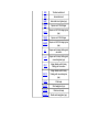
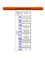
Online toolbar
The Online toolbar provides the functions most commonly used to operate and access the PLC hardware, including the start/stop control of the
PLC, the upload/download of the programs, monitoring, etc.
Online menu is divided into 9 parts:
Quick Links
Transfer Setup PLC Upload PLC Download Device Monitor PLC Password Set Clear PLC Memory PLC Clock Set Remote Operation PLC Diagnostics
Transfer Setup
Transfer Setup is used to set the communication parameters, It is a important function of PLC and PC connection.
Interface label
COM PortチMaking PLC connection with PC , You can query port in the [port (COM and LPT)] in the [Device Manager].
Baud RateチLX1S, LX2N default baud rate is 9600b/s which can not be changed.
Parity Check : Select in "odd"┷"even"┷"none" .
Date BitチSelect in 7bit or 8bit .Usually can not be changed .
Stop BitチSelect in 1bit or 2bit . Usually can not be changed.
check interval : Set any time to check
Retry time : Set the number of retry the connection
Interface Button Description
Comunication Test : To test whether the selected port allows the PC to connect with the PLC .
Execute : Save the current parameter configuration and close the window .
Close : Do not save the current configuration, close the current window without making changes
PLC Upload
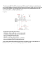
PLC Upload : The LX series PLC is through the communication line transmit data to the PLC Editor software. Make sure PLC and PC communicate
properly before uploading .
As figure below :
Button Description
[Param+Prog] : Upload parameter and Ladder to the PLC .
[Select All] : Upload parameter ladder , comment , device memory zone set to the PLC .
[Cancle Select All] : Deselect all
[Excute] : Start uploading operation
[Stop] : Terminate the upload operation
[Close] : Exit the current window
[Show] : Shows upload progress and other information , as figure below:
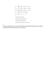
Memory Setup Description
Under normal circumstances, [Memory Setting] button is inactive, After select the [ Device Memory ] the button becomes active .
According to their need users modify detailed settings for the device, the device data name default is "Main" and "Null" .
PLC Download
PLC DownloadチPLC Editor software is through the communication line transmit data to the LX series PLC . Make sure PLC and PC communicate
properly before downloading .
As figure below :
Progress of the download, as figure below :
Device Monitor
Device Monitor : Available online to view, modify PLC register values and extension module value . Click on the button to pop up
window(monitor not start) :
Click [Monitor Start] button to begin monitoring , as the below :
Button Description
[Monitor End] : After end of the current monitor that we can not view or modify registers .
[Current Value] : Open the [Modify Device Value] window by clicking on the "Current Value" that you can modify value .
[Close] : Close [Device Monitor] window .
Device Description
[Device Name] : Input first device , Then you can view / modify the device by right "Device List" .
[Buffer Memory ] : Input a special module (such as A/D, D/A module) block number to View / Modify .
[Address] : Input a special module (such as A/D, D/A module) address to View / Modify ,It can be hexadecimal or Decimal .
Monitor display format as the below :
Note : Please ensure that normal link between PC and PLC before execute the project , otherwise it can't connect .
PLC Password Set
In the PLC-Editon , you can set a password for the PLC to maintain security. The password can be set to the "Upload Password", "download
password", "clock password"
Explain : The three types of passwords are separate (when performing operations must use separately decryption), the password can be the same
or different. It ensures the security and independence of the PLC.
as illustrated below :
Set Password
Note :
"Upload Password "," download password "," clock password " that three kinds of password setup steps are identical (only requires
the user to select the type defined)
The length of the password is 8 characters . It must be 8 characters .
When you creat a new password that the first and second confirmation password must be same .
When you excute the cryptographic operations, please ensure that connect the PLC and the PC is in the normal state, while the PLC
must be NOT RUN state (closed PLC panel switches) .
If you input the five-time password error that the password will be locked, If you want to input the password again restart PLC .
Begin Set Password
1.
2.
3.
4.
5.
Connect PLC and PC while runing the compiler .
Close the PLC RUN status .
Click on the button of [PLC Password Setup] in the [online] screen .
Open a new window, if it can't input in the [Old Password] input box . This indicates that PLC is currently not encrypted PLC.
Select the type of password then click the [Set Password] .
6.
7.
Please input a correct password according to the instructions.
Password length is not enough .
8.
Inconsistent secondary password .
9.
Password is set successfully.
Clear Password
If the PLC has no password that you can ignore this note . If PLC has set a password, you need to clear your password that you must input the
existing password . Input errors over five times refer to Note .
Clear password step :
1.
2.
3.
4.
5.
6.
Connect PLC and PC while runing the compiler .
Close the PLC RUN status .
Click on the button of [PLC Password Setup] in the [online] screen .
Select the type of password then click [Clear Passwords] .
After opening a new window, enter the password in the [Enter Password] area then click [OK] to clear passworrd .
If you enter the wrong password that prompt will be as shown below:
7.
If the password is correct , as shown below :
Clear PLC Memory
Clear PLC Memory is to clear the PLC internal data so that initialize the PLC .
Click [Clear PLC memory] , As shown below :
Module Description
Object : Displays the current link PLC information and parameters . It usually can not be changed .
Data Object : You can multi-select the object what you want to clear .
1.
2.
3.
PLC Menmory : Clear PLC memory that is initializing the PLC
Data Device : Clear all the data blocks settings (device memory area of the D register default value)
Bit Device : Clear all data blocks setting (Device Memory) of the bit device values.
Note: When you perform cleaning operations, PLC must be in NOT RUN.
Data is priceless, careful operation
PLC Clock Set
Set PLC clock, you can customize the internal PLC time to achieve accurate calculation
You can open the PLC clock set window by clicking [PLC Clock Set],
Module Description
1.
2.
3.
4.
5.
Connection Target : Displays the current link PLC information and parameters . It usually can not be changed .
Time and Calendar : You can easily select the time information and free to match time.
Get Pc Time : Let the software automatically reads the current PC time without manual calibration .
Set Clock : After completing the settings, click the button, then PLC will save the current settings .
Cancle : Don't save the current operating data . Exit and close the window .
Time
1.
2.
3.
4.
5.
6.
7.
Please ensure that the PLC and PC is normal communication .
Open the [Set Clock] window by click [PLC Clock Set] .
Select a user need time in the calendar panel or time control panel .
Year range of 1980~2079 ; Month range of 1~12 ; Hour range of 0~23 ; Minute range of 0~59 ; second range of 0~59 .
You also can get current time by click [Get PC Time](provided that the PC time is accurate) .
After configuration, please click [Save] to set the clock .
Clock set success as shown below :
Remote Operation
Remote operation can quickly change the status of the PLC and control the PLC switch .
Module Description
1.
2.
3.
4.
5.
Object : Displays the current computer port, PLC connection status and other information .
Operation : Displays the current status of the PLC, RUN or STOP .
[RUN] : PLC into RUN state .
[STOP] : PLC into the STOP state .
[CLOSE] : Close the window .
Note : Please ensure that the PLC and PC is normal communication .
PLC Diagnostics
This function concentrate most of the functionality on the online menu, Do not describe in detail, In this panel the user can view the PLC's
diagnostic data, and can quickly carry out various operations .
Tool
After the program finished, check the program to ensure the program correct in logic. If no error, offline simulator to test the operation of
downloading the program into the device.
Tool menu provides two functions : Check the program and offline simulator, as the below figure:
Check program : Check the command/soft component, logic, double coil after finish compiling the ladder diagram(command).
Simulate : Simulate the program running in the device after compiling the program.
Check Pragram
Program testing is done in written form in the program, checking the program can be timely corrected as well as location the wrong. At the
same time can quickly locate to the wrong place.
Use : As shown in the figure below, first write after completing a program, click on the "program check", check window will pop up the
program.
1.
Inspection range:
∕Current program: The program in current page;
√All program:All the program in the project.
2.
Inspection details:
∕Command/soft component inspection: Inspect the grammar of the command and the range of the soft component;
√Logic inspection: Inspect the grammar and the logic of the program;
∝Double-coil inspection: Inspect wether use the same coil output many times.
At this time only need to select the user want to perform inspection items, click on the "execution".as the below figure:
If there is no error in the program, the system will pop up "program right".If the program is wrong, then the "output" modules will be listed
at the bottom of the figure the wrong place, select the specified the wrong project, double-click can locate to the ladder diagram the wrong
position.
Simulate
Through [simulate] function, you can be very convenient to testing simulations .
preparation :
1. Enables the compiler to run
2. Create a new project, and then compile
Start online simulation:
1. Move the mouse pointer to the [tool] module, left-click [simulate] ; As illustrated below :
2. After step 1, program will pop up a new dialog box
Debugging ways:
1.
2.
Single-step debug: Execute the program step by step. interrupt after the program executes a sentence or a process.
Breakpoint debugging: Set the breakpoint in some row, the program will stop in this row when execute.
3. That do not operate for the new dialog box .
4. Move the mouse pointer to the desired position to operate the emulated instruction, right-click the specified location, select [Debug]
- [Modify current value]. As illustrated below :
5. After completing step 4, it will pop up a new dialog box that is [modify the device value] , At this time, put the device [ON], the
specific operation as illustrated below :
6. After completing step 5, there will be as illustrated below :
Program editor area
In program editor area.The user can freely switch ladder diagram and instruction list to edit and maintain program.
Insert or delete line
Insert a new line
1.
2.
Select the rows you want to insert.
[Shift] +[insert] can insert, or move the mouse to any position of the specified row . Click the right mouse button and select the
[edit] and click [insert program ].
Statement for insert of a line
1.
2.
3.
4.
Select
Method
Method
Method
the rows you want to insert.
one : [Shift] + [Ctrl] + [insert]
two : [Ctrl] + [F7]
three : Click the right mouse button and select the "edit" and Click on the [insert statement line]
delete line of program
1.
2.
Move the mouse to the rows that need to delete.Hold down the left mouse button and move the rows that need to be deleted (Can be multiple lines). Selected area to
change color .Click on the keyboard [DELETE]
Move the mouse to the rows that need to delete.Hold down the left mouse button and move the rows that need to be deleted (Can be
multiple lines). Selected area to change color .Click the right mouse button in the area of color changed, then enter [Delete or edit] and
select [Delete Row]. Statement for line delete.
3.
Move the mouse to the rows that need to delete.Holding down the left mouse button and move the rows that need to be deleted (Can be
multiple lines).Selected area to change color .Click the right mouse button in the area of color changed, then enter [Delete or edit] and
select [Delete Row] .
Copy and paste function
When ladder diagram needs a large number of the same device, use copy and paste function to save time quickly.
The step
1.
2.
3.
4.
5.
6.
The mouse moves to the editor area of ladder diagram.
Select the specified cell or draging the mouse to select a region.
Use [copy] button of [Clipboard ] in "PLC" menu, or use keyboard [Ctrl] + [C] , or use the right mouse button [copy] function.
After completing the third operation,make the designated area copy to clipboard .
Move the mouse to specify the location where it needs.
Click [paste] button on the clipboard.or using keyboard [Ctrl] + [V] : you also use [paste] function that the right button of mouse,
to cope Specifies the data to the specified .
Note
Only when a component of occupied the cell is in the left within the selected area ,the components will be copied.
When there is a vertical bar in copying area,Only when the vertical across the top and bottom cells is within the range of
choice.The vertical bar will be copied to the clipboard.
No matter to use which edit mode,When you perform paste function,only to use the overlay mode.Make the component clear within the
range of pasting.Then paste every compoent of the clipboard one by one.
Modify the ladder diagram component
Modify the ladder diagram component
The step of modifying the ladder diagram component
1.
2.
You must ensure that it can modify the ladder diagram component in [Write Mode] of current state.
Use the mouse to select components that need to be modified.Double click the left button of mouse or click the [Enter] key on the
keyboard
3.
4.
5.
After completing the second step,there will popup dialog of output instruction.
Put the corresponding instruction of the selected component input the dialog.
Click on [sure] to save the changes
noteチ
Instruction of revision must be able to verify by the proper instruction, it can be saved.
Contact component Of occuping a cell(normally open, normal close, rising edge, failling edge, inversion, Stepping)should not be
modified with the compared contact each other.
All of the contact component can't modify each other with coil or application instructions.
Delete the ladder diagram component
The steps of deleting the ladder diagram component
1.
2.
You must ensure at [write mode] of current status that you can delete the ladder diagram component.
Using mouse to pitch on the element grid that want to delete.clicking the left button of mouse. Selecting the part is lock-in by
blue frame.Then you can click keyboard [DELETE] to delete.
3.
Delete the horizontal and vertical linesチin this special ladder diagram,you can do the method that step 2 or 3 to Select the
target.Then Click the icon [CF9 ] or [CF11] to delete in the [Ladder diagram symbols] function of menu.
Enter the instruction of ladder diagram
Entering the instruction of ladder diagram's method have 5 kinds.
The method of direct input The method of instruction set input The method of double-click cell The method of instruction help The symbol
of ladder diagram/A shortcut method
The method of direct input
1.
2.
3.
4.
5.
6.
Move the mouse, left-click on the specified cell.
Directly input the specified command.The system will automatically pop up input box of ladder diagram.
Enter the complete instructions and parameters in the dialog.
Click on [OK] or [Enter] button in the keyboard
System will verify the correctness of input, If it check, there is generating graphic symbols of the instruction.
If prompt is incorrect or can not be saved, please return to find the cause of the error.
The method of instrcution input
1.
2.
3.
4.
Move the mouse to the form on the left of [the Project Management] interface
Expand [Instruction Set]
Open the command tree of users need
Pitch on instruction that is user need.The left button of mouse clicks to select.Draged into [Ladder diagram into area] and placed in
the designated area.
5.
After finishing step 4, it will popup [Ladder diagram input]
6.
Put the right operand in the input box.
7.
click on ; [Save] or keyboard [Enter]
The method of double-click the cell
1.
2.
3.
4.
The mouse moves to the designated areaコdouble-click the left button of mouse.
Popup [Ladder diagram input] , input the correct order in the input box.
click [Save] or keyboard [Enter].
If the prompt is wrong or can't save.please come back ladder diagram to find the error.
Method of instruction to help
1.
2.
3.
4.
5.
6.
The mouse moves to the designated area, double left click .
popup [ladder diagram input]
click [help], popup [Instruction help]
After select the instructions that need to input, Click [Details] button, popup [Instruction Wizard]
Wizard interface chooses the right operand according to different instructions.
After choosing the specified instruction, click [Ok] to save data and complete the instruction input
Ladder diagram symbols/A shortcut method
Ladder diagram symbols located in the PLC menu,as the below :
After selecting cell,then click the menu. "Ladder diagram symbols" You enter operands on the ladder diagram to complete the command input.If
the instruction is the application instruction. After click the faceplate "F8",You should enter the complete application instructions and operand
in the ladder diagram input box that finish the instruction.You also use corresponding shortcut of instruction. (See the instruction_list) input,
operation method and "Ladder diagram symbols is the same."
After completion of the instruction input and click ladder diagram input box "sure " button.It will display in the ladder diagram editor
area.
Note:
1.
Some instructions only input in the editor of order listクILグ.You can not input in the ladder diagram,such sa MPS┷MPP.When you
directly input in the ladder diagram of these instructions.It can not generate any component.
2.
Because coil and application instructions representative the line is over in the Ladder Logic Program.You can not enter any component
behind these components.
3.
Due to the vertical bar can take up two rows of space. At the time of inputting a vertical bar,if the location of next line just is
center section of other component,then the vertical bar can not enter.
4.
The maximum number of columns is 13 line.
compile program
Compiler refers to after completing programming or after completing the design of the ladder, to generate a program that must be compiled
As the belowコIf the program is not compiled, [program compilation] Button is highlighted and you can use it.
If program compilation is completed, [program compilation] Button is not to be used.
The procedure for compiled
1.
2.
3.
4.
Open this softwareコthen create a new project.
Compile the programs in the ladder diagram program.
After completing the design,click on the [compiled regional] Button of the program to compile.
As shows in the figure below indicates success.
5.
If there is a mistakes in the program as following figure,please modify carefully.
Instruction table editor
The software not only provides the ladder diagram editor,but also provides the instruction table editor.Instruction list is used for enter of
instruction and operand.The way of inputing instruction is the same as ladder diagram.After input the instruction,system will calculate the steps
of instruction,and automatically align instruction, operands.As the below :
Instruction input
The steps of instruction input
1.
2.
The first is to create a new project.
In the menu bar [program compilation] area, clicking [Program switch] will switch instruction table editor from the ladder diagram
editor.
3.
4.
5.
If there is uncompiled program in the ladder diagram editor,[Edit Comment] please.
The mouse moves to shadow of instruction table. Open it by double-left click.
You can input the specified command in the new window.then click [save]
Copy, cut and paste of instruction
< p>
1.
2.
3.
Creat a new project and switch to the command table interface.
Select the area or element that need to be copied,cutted. Click [Ctrl+C] or [Ctrl+X] to copy,cut on the keyboard.
After finish step 2, move the mouse where wanted then [Ctrl+V].
Find and replace function
The same as most of OA software,Standard search/replace functions are provided in sequential function chart.
1.
2.
3.
The first is to create a new project.
Open the interface of find and replace and enter what you want.
About the function's description of finding and replacing window, please shift "————————"
other description
Step No. : Step No.refer to location of instruction.It can be use quickly positioning of instruction and improving the readability of the
instruction.ladder diagram-instruction list switch:If program logic is wrong,it can not switch.
The function description of right-click for program editor area
In the program editor area, clicking the right key of mouse. It will popup commonly used functions button. It can greatly improve the
development efficiency of developers.
Revocation : Cancel the current operation and roll back the previous step.
Redo : Rollback undo operation
Cut : Cut the selected ladder diagram in the ladder diagram.Cut the selected command line in the list of instruction.The content is
store in the clipboard.
Copy : Copy the selected ladder diagram in the ladder diagram.copy the selected command line in the list of instruction.The content
is store in the clipboard.
paste : At the selected location, Paste the data in the clipboard.When no data in the clipboard, Paste is not available.
Compile : Compile the current program.
Edit Optionsチ
Insert program line:In the currently line insert a empty line in the ladder diagram or instruction list.
Line statement line:In the currently line insert a blank statement in the ladder diagram or instruction list.
Delete row: Delete the currently rows in the ladder diagram or instruction list.
Insert columnチIn the ladder diagram (It is not available in the instruction list), add a blank instruction at the place of selected
instruction.Other instructions move right in one grid.
Delete columnチIn the ladder diagram (It is not available in the instruction list), Delete the currently selected commandコOther
instructions move left in one grid.
Search
Find Device : Open the search/replace window.The default search page of device.If the selected instructions contains soft component
in the ladder diagram or instruction list."Search the device". The default for the soft component of selected instruction.If it is
nothing,let it empty.
Find Instruction : Open the search/replace window.The default search page of instruction.If in the ladder diagram select
instruction┷"Search instructions". The default for selected instruction.If it is nothing,empty it.
Find character string : Open the search/replace window.The default search page of instruction.If in the ladder diagram select
character string┷"search character string ". The default for character selected string.If it is nothing, empty it.
View
Show Comment : In the ladder diagram (Instruction list is not available), show the soft component annotation.
Show Alias : In the ladder diagram and instruction list,display the alias of device.
debugging
Modify the current value : In monitoring mode (Write mode is not available), Open the written dialog box of device.Modify soft
component values of the currently instruction.
Program
MIAN for the program name, the project can only exist a program.Double clicking on the MAIN can open the ladder diagram in the users area,
then the user can edit program.
When there is no program, select the program right click -> new window to open the new program,then the following figure:
Program module : Right click on one of the program nodes under the program block, and select open program, delete program (the main program
can be deleted) in the pop-up menu.
Note : A project is only one MAIN program.
Device Comment
Device comment moduleチA document ". wcp" and only one called COMMENT "Device comment" module; The device comment is defined and managed by
the symbol table. The device comment could be directly modified in the ladder diagram device comment mode, and the modification in ladder diagram
will be automatically updated to the symbol table.
Double click on the "COMMENT" in the following figure interface:
Interface label, instructions:
DeviceチType in the name of the soft components correctly and press enter to determine, annotated list will locate the input soft components
and selected (shown in blue).
Comments list into 3 columnsチDevice name,Device comment,Device alias.Device Name column shows for gray represents unavailable to edit,
device comments column when device don't display it is white, on behalf of the editable. Click the comments list: Choose device line (shown in
blue),double-click on the device comment or alias, pop-up edit box, for editing. The device comment values allow 16 characters, device alias
allows only 8 characters.
Select the device range:Click comments can choose soft components interval, change list of soft component.Blue indicates that the device
range is selected, black indicates the interval in the device comment or aliases, white indicates that the interval is not a device comment or
aliases.The device range of 1s and 2n is different. The device range is as follows:
Interface button, instructions:
Show the commented : Comments list displays all comments or alias device.
Import CSV : Choose the CSV file to import, all right the CSV file in device comment and alias imported into the software(Can only be the CSV
file, LX2N comments into LX1S projects, if there are more than 1s scope of device comment complains).
Export CSV : Put all the editing device information of device comment or alias, export to the local disk to save the CSV file.
Parameter
Parameter : According to the need to set the PLC parameters; There is only one "PLC parameters" do not delete and right click on the new;
Click on the upper right corner of the symbol "x" to close the dialog changes not saved;
Double-click LX1S series engineering "PLC parameters" nodes the below (left) interface; Double-click LX2N series engineering "PLC parameters"
nodes appear the picture on the right as show in the interface.
Interface label, instructions:
Memory capacity include:Memory capacity, comments, capacity, register file capacity, set the annotation capacity and capacity of register
file which cannot be out of range, If it out of range that the modificy is not successl; Program capacity = memory capacity - comments capacity *
500 * 500 - register file capacity.Program capacity must be greater than zero, or wrong modify will be not success,
PLC name:Input PLC name, allow 32 bytes, one of the Chinese account 2 bytes, interface is as follows:
PLC System(1)チSelect terminal operation, interface is as follows:
CheckチCheck the current settings, whether the "program capacity" is greater than zero. If "program capacity is less than or equal to zero,
the examination will be successful by setting, and at this time click the ∠ button will be an error.If "program capacity is greater than zero,
the inspection can be done, at this time click the ∠ set success;
Default:Click this button to restore the default settings.LX1S default memory capacity, Annotation capacity, Register file capacity 2000, 0,
0, respectivelyコLX2N default memory capacity, Annotation capacity, Register file capacity 8000, 0, 0, respectivelyコLX2N series memory capacity
has 2000, 4000, 8000, 16000 four options.
EndチComplete the correct PLC parameter change, and setting.
CancelチCancel the PLC parameter settings and change before the parameter settings.
PLC System(2)チInterface is as follows:
Protocol : Protocol Select
Stop bit : Select stop bits
Control line : Whether you need the control line
Header : Whether you need the header
Terminator : Whether you need the terminator
H\W Type : Choose H\W type, the RS-232 or RS-485
Station number setting : Set up the station number, range 00H~0FH(Hex)
Control mode : Default
Transmission speed : Choose the transmission speed
Data length : Choose data length
Parity Choice : Odd or even
Sum check : Whether you need sum check
Time out judge time : Set the timing out of judge time
Transmission control procedure :Default
Interface button, instructions:
Check : Check the current settings, whether the "program capacity" is greater than zero. If program capacity is less than or equal to zero,
the examination not through setting is not successful, and click the "End" button will be an error at this time. If program capacity is greater
than zero, then inspection, click on the "End" set the success at this time.
Default : Click this button to restore the default settings.LX1S default memory capacity, Annotation capacity, Register file capacity 2000,
0, 0, respectivelyコLX2N default memory capacity, Annotation capacity, Register file capacity 8000, 0, 0, respectivelyコLX2N series memory
capacity has 2000, 4000, 8000, 16000 four options.
End : Complete the correct PLC parameter change and setting.
Cancel : Cancel the PLC parameter settings and change before the parameter settings.
Device Memory
Device memory : Download PLC is used to set the PLC data block data, PLC uploaded displayed when reading data from PLC data block.
New device memory : The right mouse button to select "memory" soft element node -> "new", to create a new soft element memory file(file name
any character, up to 33 characters in length, and each time can only download one).Distribution of interface is shown in figure 1 as follows:
Interface label, instructions:
Device name: Enter the device you want to search, press Enter to search and locate the component; you also can right click "search the
device" in the editor area -> to search the location of soft component.
Divided into 9 interval C, D, M, S, T, X, Y, S, X, Y, interval of them can read an editor, M range can only enter 0 S and 1 S. The device
range list belowチ
Editor areaチTo enter each interval to set value.
Coumn Formatチ7 kinds of data of Bin, Oct, Dec, Hex, real Numbers, strings, ASCII format; A format one color: Bin(Red), Oct(Pink), Dec(Blue),
Hex(Brown), Real Numbers(Orange), strings(Blue Green), ASCII2(Green).
The transformation of different formats:
Method 1.Click on the select box format in different formats;
Method 2.The right mouse button -> display format -> choose to convert the format.
The matters need attention of various formats using :
Binary can only input Numbers 0 or 1;
Octonary only Numbers 0~8;
Decimal number only Numbers 0 to 9.
Hexadecimal can be 0~9 or a~f or A~F various combinations, such as 1af;
Real number can only be 32 bit, need to selecte two cell Ⅱ click on the "32 bit" Ⅱ click on the "real" to edit the set of real
Numbers;
A string of hexadecimal characters, divided into visible characters, invisible characters;
Visible characters can enter only two characters, example: input characters [#7e] is displayed for [~];
Invisible Characters with "#" in front of the logo, example: input is invisible Characters [#7f] are shown as [#7f#00];
ASCII input two characters.
Data size: 16-bit and 32-bit
When the length of 16 bits each the size of the data format : Binary 0000000000000000~1111111111111111ヂb.Octonary 0~1777777ヂc.Decimal
number -32768~32767ヂd.Hexadecimal 0~FFFFヂe.Strings two characters in lengthヂf.ascii two ascii code value.
When the length of 32 bits each the size of the data format : Binary 00000000 00000000 00000000 00000000~11111111 11111111 11111111 11111111
ヂb.Octonary 0~37777777777ヂc.Decimal -2147483648~2147483647ヂd.Hexadecimal 0~FFFF FFFF FFFF FFFFヂe.Strings four characters in lengthヂf.ascii
four ascii code valueヂg.Real numbers 圙1.1754946E-38~圙3.4028235E+38.
Interface button, instructions:
Displays all existing device of the input value and can be directly in the interface editor.
Import EXCEL : Can import edited from the local computer excel file (only excel spreadsheet), After successful imported there is display as
"Show existing Device" interface.
Export EXECL : To the set value can be all of the soft components export to excel file stored in the local disk.
Instructions
Available instructionsチAll, Basic Sequence, Step Ladder, Program Branch, Transfer and Compare, Arithmetic Operation, Rotation and Shift,
Data Processing, High Speed Processing, Facilitate, Peripheral Device IO, Peripheral Device SER, Float-Point, Locate, Clock Calculate, Peripheral
Device, Contacts Compare.
Output Window
The information output window can provide the user with the results after software has executed the operations, including the result
information of the three types of operation: compilation, communication and conversion.
If there is no error in the program, the system will pop up "program right".If the program is wrong, then the "output" modules will be listed
at the bottom of the figure the wrong place, select the specified the wrong project, double-click can locate to the ladder diagram the wrong
position.
Search/Replace Function
Search-and-replace function,it is similar to the search-and replace function of MS OFFICE,can realize positioning in a large amount of
data,the user can do the bulk addition,deletion,modification,search for the block data,that can greatly improve efficiency.
Method of use: Open the main program, build a new project, click on the [Ctrl] + [F4] in the keyboard,then pop up search-and-replace
interface, as figure below.
Buttons are divided into device, instructions, strings, A/B contact, results, 5 classes, as figure below; Click on any one will switch the
corresponding interface.
Modify Device Value
"Modify Device Value" divide into modifying internal registers of the PLC;Coil value; modifying the register values of expansion equipment.
As the below
Detailed annotation of picture as below;
PLC Internal Device
∕ a."Device" is the register,coil(such as CO,M1) of the data need to be modified in the range of plc.
b."Data type" include Word (single byte), Bit(binary 0 or 1), Double Word (double byte).
c." Value" is specific value that need to be modified.(corresponding to the number that is in the range of "data type"), such as -120.
d.Data format can be decimal (single byte -32768~32767,double byte -2147483648~2147483647) and hexadecimal(single byte0~FFFF,double byte
0~FFFFFFFF).
e.Click "Set" to save all valid setting.
√The results of performing: Recorded the ‐device– ,–data type–,–setting value– that revised successfully as list.
∝Record list :
Click any one in the list and click "Delete" to delete it.
Clicking "Empty the list ". Then clear the records in the list.
Selected any one in the list, Click "Reflected in the input field" will reflect every item of ∕.
PLC circumscribed extension module.
a."The start of module":The number of expansion module(such as 0 block).
b."address" is writable address inside of expansion module.address type can be decimal or hexadecimal.
c."data type" Including Word (single byte)┷Bit (binary 0 or 1)┷Double Word (double byte).
d."value" It is specific numerical that will be modified.(correspondence "data type" number of the range), Such as -120; Type is is
decimal or hexadecimal.
e.Range: decimal(single byte -32768~32767, double byte -2147483648~2147483647), and hexadecimal(single byte0~FFFF, double byte
0~FFFFFFFF).
f.Clicking "set" Writing the rightly seted value of the range into the selected device.
Note:
1.MotifyThe value of device must with PLC communicate to finish.
2.Devicemustin the range of the corresponding models of PLC.
3.Input valuemustwithin bounds decimal ( single byte -32768~32767, double byte -2147483648~2147483647 ), hexadecimal(single
byte0~FFFF, double byte 0~FFFFFFFF).
The status bar
Indicate language, status of capital letters and small letters, status of numeric keyboard lock, status of rewi/insert, COM port, engineering
model, The steps of current program/total steps of program and so on.
Language : Language Type of Device display.Highlight means start using.
status of capital letters and small letters : status of english input.
numeric keyboard lock :Whether the numeric keyboard is available.
Write/insert mode : Ladder diagram edit mode.
COM port : Communication COM port.Clicking it will popup window of Communication Settings.
Project Type : Showing the Plc type of current engineering.
The steps of current program/Total steps of program
instruction/Total steps of program.
: The program's edit page, The program's steps of currently selected
Soft components List
The soft component list is used to display the soft component of specified type. You can check its usage and edit it.
The instrusction
1. The soft coponent selection drop-down box : Select and diaplay the usage of the current soft component(from the NO.0) :
2. The initial soft component drop-down box: Input the full name or number of the soft component then click on Enter or the search button to
select the usage(from the initial number).You can search again by the search records in the drop-down list.
3. Search button: Search for what you want. If the initial soft component is empty, there will be a prompt to input the soft component.
4. Search range: The search range displays automatically. It can not be edited.
5. Use the list item to open and close the soft component.
6. Soft component list item: includes the commands, steps, and the type in the soft component peogram.
7. Soft component annotation and alias column:( the backgroud is white). Double click to edit the annotation and the alias.
Dispaly options
1. All soft cpomponent: Select the soft component of this kind after it is selected.
2.Use the soft componnet: according to the contatc and the coil options, select the soft component used of this type after it is selected.
When no contact and coil checked, it will display all the soft component of this type.
When contact(coil) checked, it will display the soft component of the contact(coil) type in the program.
When both the contact and the coil checked, it will display the soft component of the contact and coil in program.
3.No soft component: It will dispaly the soft component whose type is not used in the program.
Comparison table
The comparison table is used to show the usage of the specified soft component or the all soft component.
The instructions
1. Soft component input box: input the name of the the soft component wanted then click on the Enter or search button to select its usage.
2. Search button: Search for waht you want.
3.Display all buttom: Display all the soft component and all the commands.
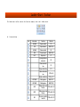
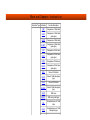
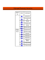
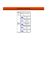
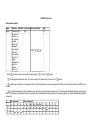
Types of software components
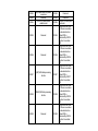
PLC is supported by the soft component types in the following table:
SN
Component
Type
1
Input Relay X
2
3
4
5
6
7
8
9
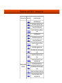
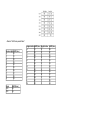
Features and classification
PLC hardware corresponding bit component
digital inputs
PLC control output corresponding to digital
Output Relay Y
components
Common intermediate relay M-bit
Intermediate
components; system special relay M-bit
relay M
components
State relay S
Step control components with status flag
Timer T
With 1ms, 10ms, 100ms step of 16bit timers
With 16bit/32bit up / down type counter,
Counter C
high-speed counter, single / duplex various
counter
Data register D Data register D; data register indirect
addressing V, Z, D register file
Jump pointer P, subroutine pointer P,
Pointer P ┷I
interrupt subroutine I, a high-speed input,
timing, counting and other interruptions
Constant K┷H Binary, decimal, hexadecimal, floating point,
etc.
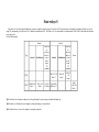
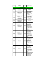
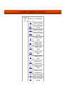
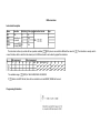
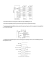
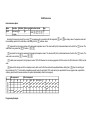
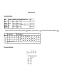
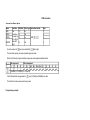
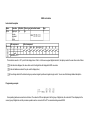
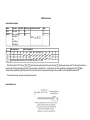
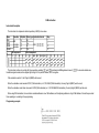
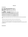
Input relay X
The input relay X represents the PLC status of the external input signal components. And it can get through the input port to detect the external signal status. 0 is for external
signal open circuit, and 1 closed.
It cannot modify the state input relays in the way of program instructions. Contact signal (normally open, normally closed type) program can be used an unlimited amount of
times by the user.
The number of Relay signals is X0, X1…X7, X10, and X11 and so on. The serial number is in octal numbers. Controller counter signal, external interrupt, pulse catch functions
through the input port X0ㄐX7.
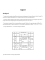
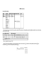
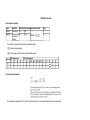
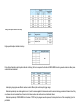
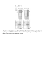
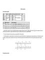
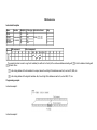
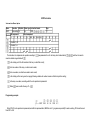
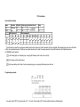
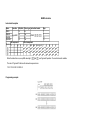
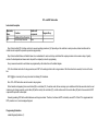
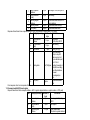
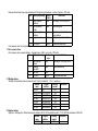
Type
Input
Output
LX1S-14MR/MT
8 point
6 point
LX1S-20MR/MT
12 point
8 point
LX2N32MR/MT
16 point
16 point
LX2N40MR/MT
24 point
16 point
LX2N60MR/MT
36 point
24 point
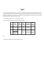
Output relay Y
Output relay is directly related to the external user to control the hardware port of the software component. It corresponds to the physical output port of PLC. The component
status of relay Y will be sent to the state of the hardware port on the PLC. 0 indicates that the output port is open, and 1 closed.
The number of relay Y is Y0, Y1,...Y7, Y10, Y11 and so on. The number sequence is in octal numbers. Relay device in the user program can be used an unlimited number of
times.
The hardware can be divided into the following categories: relay type, transistor type, solid state relay type, etc. according to different output devices. If it has the output
expansion module port, relay Y will be numbered sequentially from the main module.
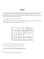
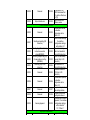
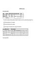
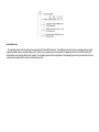
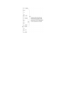
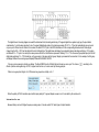
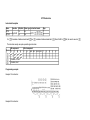
Auxiliary Relay M
Auxiliary Relay M components is used as an intermediate variable during the execution of a program, as auxiliary relays in the practical power control system which is used to
transfer the status messages. It can use the word variable formed by M variables. M variables is not directly linked with any external ports, but it can contact with the outside world
by the manners of copying X to M or M to Y through the program coding. A variable M can be used repeatedly.
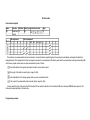
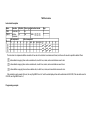
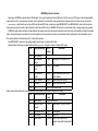
Auxiliary Relay M can be identified with the symbols of M0, M1,...,M8255. The numbering system is numbered by 10 hex. The variables that are more than M8000 are the
system-specific variables,which is used to interact with the PLC user program with the system status; part of the M variables have the feature of power-saving,
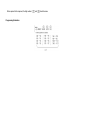
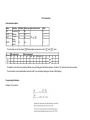
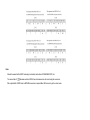
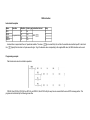
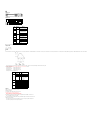
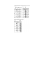
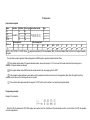
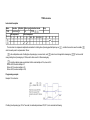
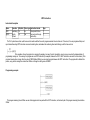
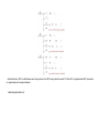
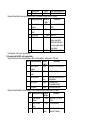
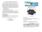
Type
General
Latched
Latched specifically
Special
LX1S
M0-M383 384
Point’3
-
M384-M511 128
Point’3
M8000-M8255 256
Point
LX2N
M0-M499 500
Point’1
M500-M1023 524
Point’2
M1024-M3071 2048
Point’3
M8000-M8255 256
Point
Tip1: Non-latched area. The non-latched area can be changed to a latched area with the parameter setting.
Tip2: Latched area. The latched area can be changed to a non-latched area with the parameter setting.
Tip3: Cannot change the characteristics in order to maintain the power-off by parameter setting.
The regional distribution of the generally used auxiliary relays and the auxiliary relays that are latched in the programmable controller can be adjusted by adjusting the settings in
the parameter.
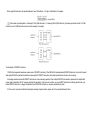
Programmable controller has a large number of special auxiliary relays. Each one of them has their specific functions which can be categorized into the following types:
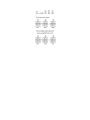
1) The special auxiliary relays used for contacts. For instance:
M8000: Operating monitor (connected in operation). It is commonly used before the command signal execution.
M8002: The initial pulse (only connect shortly at the beginning of operation), it is commonly used as the initialization command.
M8012: 100ms clock pulse. It is used to generate a signal at during regular interval flips.
2) Coil-driven special auxiliary relays provide driven coils for user programs, and it is used to control the operating status and the status of execution of the PLC. For instance:
M8030 : The command for battery lighting and polar tube lighting.
M8033 : Continue exporting when stopping
M8034 : Total ban on export
M8039 : Constant Scanning
Note:
M component is effective when there is a driver and two cases after the execution of the END command; users cannot use the special auxiliary relays that have not yet been
defined.
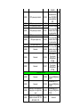
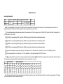
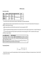
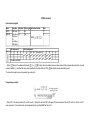
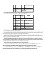
State relays S
State relays S is used to design and handle step procedures, control the transfer steps of the state S by STL step instructions, and simplify programming. If there is no way of
using STL programming, S can be used as M. S variables are identified with S1...S999 and so on. The serial number is a decimal number. Part of the S variable has the function of
power-down save.
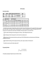
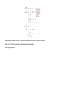
See the following table:
General
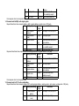
Type
General
Latched
function
of
getting
back to
Initialization origin
point
under
IST
command
LX1S
-
-
LX2N
S0-S499 500
Point’1
S0-S9 (10
Point)
-
Latched
S0-S127 128
Point’3
function
of
getting
back to
Initialization origin
point
under
IST
command
S0-S9 (10
Point)
S10-S19
(10
Point)
-
-
-
S900S999 100
Point’2
S10-S19
S500-S899
(10 Point) 400 Point’2
Tip1: No latched area. Parameter settings can be changed through the power outage to maintain the leading city.
Tip2: Latched area. Parameters can be changed by setting the leading city of non-latched.
Tip3: Latched features. It can not be changed by setting the parameters.
Alarm
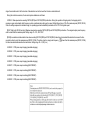
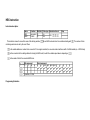
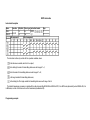
Timer T
The timer is used to perform the timing function. Each timer contains coils, contacts, and counting time value register. When the coil sounds (with sufficient power), the timer
starts timing. If the timer's registered value reaches the preset value, the contacts activate, and other contacts (NO contacts) are closed, while b contacts (NC contacts) disconnect. If
the coil power shuts off (insufficient power), the contacts will restore to their initial states and the value will automatically be cleared. Some timers have the feature of accumulation
and shut-down.After a restart, it will even keep the value before the shut--down.
Timer T is expressed by the symbol of T0, T1, ... T255. Its serial number is in 10 decimals.
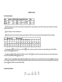
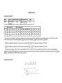
Timers have different timing steps. For instance, 1ms, 10ms, 100ms, and etc. See the following:
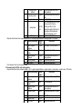
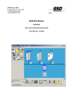
Type
100ms
0.1~3276.7s
LX1S
T0-T31 32 Point
100ms
10ms
0.01~327.67s 0.01~327.67s
T32-T62 31
Point
T0-T199 200 Point
LX2N General application
T192-T199
-
T32-T62 31
Point
1ms retentive
0.001~32.767s
100ms
retentive
0.1~3276.7s
T63 1 Point
-
T200-T245 46 T246-T249 4 Point T250-T255 6
Point
Keeping the interrupt Point Holding
Tip:
The timer number is not for the timer, and it can be used as a data register to save values.
Counter C
The counter is used to complete a counting function, and each counter contains a coil, contacts, and time value register. When the counter coil drives a signal from the OFF to
ON, the value of the counter is increased by 1. If the time value reaches the preset time value, the contacts act, Contact a (Contact NO) closed, Contact b (Contact NC)
disconnected. If the timer value is cleared, output of Contact a is broken, Contact b (Contact NC) closed. With power-down to maintain a cumulative and other characteristics, after
re-powering, some of the counters can maintain the value before powering-down.
Counters are identified by C0, C1, ..., C255, ordered by 10 hexadecimal numbers.
Counters have the width of 16bit and 32bit. There are the single-way counting type, change counting type, bipolar counting type, etc. Some of the counters have the option to
maintain values when powered-down. Select the appropriate counters according to need when using.
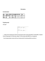
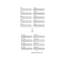
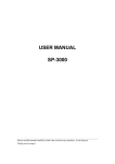
32bit counters 2,147,483,648~+2,147483647
16bit counters 0~32,767
Type
General
Latched
Latched
specifically
Special
LX1S
C0-C15 16
Point’3
C16-C31 16
Point’3
-
-
LX2N
C0-C99 100
Point’1
C100-C199 100
Point’2
C200-C219 20
Point’1
C220-C234 15
Point’2
1 Non-latched area. The non-latched area can be changed to a latched area with parameter setting.
2 Latched area. The latched area can be changed to a non-latched area with parameter setting.
3 You cannot choose the option to maintain a value when powered-down by parameter setting.
Tip:
A counter number not used as a counter, can be used as a data register to store data.
Register D
Data Register D
The register is used for data computation and storage � items such as timers, counters, and analog parameters of the operation. Each register is 16 bits wide. If using the 32-bit
instructions, it will be composed of adjacent registers to use as a 32-bit register.The address low byte is low byte, and the opposite is high byte.
In LX series PLC's instructions, the majority of the data is carried out by a number of processed symbols.For the 16-bit register, bit-15 is the sign bit (0 for positive numbers; 1
for negative numbers).As for the 32-bit register, high byte bit-15 is the sign bit.The range of values is : from (-32 , 768) to (+32, 767).
When the data need to be addressed as 32-bit, it can be as two adjacent D registers composed of 32- bit double word. For example, when we need to visit D100 in a 32-bit
format, the high-address register D101 is high byte, and the high byte of 15 is a two-word sign bit.The following values can be handled: -2 , 147 , 483 , 648 to 2 ,147 , 483 , 647.
The register is identified with D0, D1, ..., D9, 999, carried out according to the decimal number.
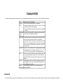
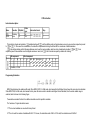
Type
Latched specifically
General Latched
D0D127
LX1S
128
Point’
3
-
According to parameter
D128- setting, D1000-D2499
D255 128 can be used as a file
Point’3 register
D0D200D512D199
D511
D7999 According to parameter
LX2N
200
312
setting,after D1000 can
7488
Point’ Point ’ Point’3 be used as a file register
1
2
Tip1: No latched area.Parameters can be changed by setting the field latched.
Special Designated
File
D8000D8255 V0-V7 Z0256
Z7 16 Point
Point
D8000D8255
256
Point
V0-V7 Z0Z7 16
Point’3
Tip2: Latched area.Parameters can be changed by setting the field of non-latched.
Tip3: It cannot be changed by setting the parameters' latched features.
Index Register V, Z
Index register V, Z is the same as the common data register, which is for the numerical data to read and write a 16-bit data register. It is a total of 64: V0~V31, Z0~Z31.
The index register has the same use as the common data register, and it also can be used with other numbers or values of soft components.But we need to be aware that LD,
AND, OUT, and other basic sequential control commands or a step ladder program cannot be a soft component number used in combination with the index register.
File register D
After data register D1000, it is the register to remain. Through parameter settings, it can be specified from 1 to 14 blocks for the backup file. But a record for each additional block
of 500 steps of the procedure would reduce the storage area. When part of the D1000 is set to file register, the rest can still maintain a register used as a general one.
Pointer L, I
Point L is applied as the entry address of jump routines and as well as the label of subroutine starting addresses; Pointer I is applied as the label of starting address of interrupt
routines, and its codes are allocated to decimal digit as the table below shows:
Branch
Insert
Counter
interrupt
I00_(X000) I10_(X001)
P63 1 Point I20_(X002) I30_(X003)
I40_(X004) I50_(X005) 6 Point
None
None
P0-P62
I00_(X000) I10_(X001)
LX2N P64-P127 P63 1 Point I20_(X002) I30_(X003)
127 Point
I40_(X004) I50_(X005) 6 Point
I6__
I7__
I8__ 3
Point
Type
Insert and Input
None
LX1S
P0-P62
63 Point
End Jump
I010 I020
I030 I040
I050 I060 6
Point
Note:When an interrupt timer (1 msec resolution) is used in an interrupt routine or within a ‘CALL’ subroutine, the output contact is activated when the first coil instruction of that
timer is executed after the timer has reached its preset (maximum duration) value.
Constant K,H,E
According to different application and purposes, LX series programmable controller uses 5 types of values. Their role and functions as follows:
Type
Decimal
(DEC)
Application Notes in Programming
The set value of timer and counter (K is a constant)
The number of Auxiliary Relay(M), Timer(T), Counter(C), Status(S)
and so on (the number of soft component)
The value and command action in the Operand, which are applied (K
is a constant)
Hexadecimal As with the 10 decimal number, it is applied in the operand and the
number
specific actions in the application commands.
(HEX)
Binary (BIN) Using decimal number or hexadecimal number to design the value of
the timer, counter or data register. However, in the internal
programmable controller, these figures are dealt with binary numbers.
Moreover, when monitoring external devicesコthese soft components
will be converted to a decimal number automatically (16 hex can be
converted as well)
Octal (OTC) Using 8 hex values to distribute the soft component number of Input
relay and output relay. Use the binary values of [0-7, 10-17, ... 7077, 100-107]. [8, 9] does not exist in the 8 hexadecimal number.
BCD
BCD is a way of using 4-bit binary to represent decimal values. The
processing of these numbers is simple. Thus, it can be used in the
digital switch of BCD output format and the display control of seven
segments.
BIN float
Programmable controller has the function of high-precision floating
point capabilities. In the center, use binary (BIN) floating-point to
conduct floating-point operations
Decimal
Decimal floating-point value is only used for monitoring and
floating point improving readability.
Constant K
[K] is the symbol that expresses the 10 decimal integer. It is used to set the value of the timer, the counter, and the value in the operand. In the 16bit commands, the constant K
ranges from -32768 to 32767; in the 32bit commands, the constant K ranges from -2,47,483,648 ~ 2,147,483,647.
Constant H
[H] is the symbol that expresses the 16 decimal integer. It is used to set the values in the application command operand. Constant H ranges from 0000 ~ FFFF;in the 32bit
commands, the constant K ranges from 0000,0000 to FFFF, FFFF.
Constant E
[E] is the representation of a 32-bit floating point. It is used to set the values in the application command operand.
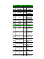
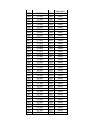
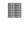
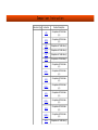
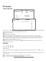
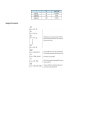
Special system component
M8000~M8255コD8000~D8255 are defined as special components of which functions are described as following:
M
D
D component
M component description
component
component
description
System operation status
ON when user program is
Monitor timer of user
M8000
D8000
running
program operation
Single board program
version, for example
M8001
M8000 status is inverted
D8001
24100 2N= 24, 1S =
22,100 version V1.00
ON during first period of user
Program capacity, 4K, 8K
M8002
D8002
program
and 16K etc.
Fixed value 0X10,
M8003
M8002 status is inverted
D8003
internal memory of PLC
If any of M8060~M8067 [except
Wrong BCD value of
M8004 for M8062] is ON then M8004 is D8004 M8060~M8067, normally
effective
0
Actuated when battery voltage
BCD current value of
M8005
D8005
is too low
battery voltage
Threshold value of low
Actuated when battery is too
M8006
D8006 battery voltage detection,
low [latch]
initial value is 2.6V
AC power lost for 5ms then
Time of saving M8007
M8007&M8008 will be actuated,
M8007
D8007 actions, reset to 0 when
but the program continue
power is lost
running within D8008
If the power is lost within
D8008, then the user program
AC power lost detection
M8008
will stop running when M8008
D8008
time, default 10ms
changes from ON?úOFF.
M8000 is OFF
Module number of
Actuated when the extension
M8009
D8009 extension unit which
unit loses 24V power
loses 24V power
System clock
Current scan time, from
M8010
reserved
D8010 step 0 of user program
(0.1 ms)
M8011
M8012
M8013
M8014
Clock oscillator of which period
is 10ms
Clock oscillator of which period
is 100ms
Clock oscillator of which period
is 1s
Clock oscillator of which period
is 1 minute
D8011
D8012
D8013
D8014
M8015
Clock stop and preset
D8015
M8016
Stop clock read and display
D8016
M8017
?à30 seconds correction
D8017
M8018
Installation detection
D8018
M8019
Real-time clock (RTC) error
D8019
Instruction flags
M8020
Operation Zero flag
D8020
M8021
M8022
M8023
M8024
M8025
M8026
M8027
Operation Borrow flag
Operation Carry flag
Reserved
BMOV instruction direction
HSC instruction mode
RAMP instruction mode
PR mode
D8021
D8022
D8023
D8024
D8025
D8026
D8027
M8028
Reserved
D8028
M8029
M8030
M8031
M8032
Instruction (PLSR and so on)
D8029
execution complete
PLC operation mode
If it?ˉs ON then even battery
voltage is low the alarm BATT.V D8030
LED not lit
Non-latch memory all clear
D8031
when it's ON
Latch memory all clear when it's
D8032
Minimum scan time (0.1
ms)
Maximum scan time
(0.1ms)
Clock second (0~59)
Minute of Real-time clock
(0~59)
Hour of Real-time clock
(0~23)
Day of Real-time clock
(1~31)
Month of Real-time
clock(1~12)
Year of Real-time
clock(2000~2099)
Week of real-time clock
Input filter constant 0~60
of X000~X007 [default
10ms]
Reserved
Reserved
Reserved
Reserved
Reserved
Reserved
Reserved
The same address with
Z0
The same address with
V0
Reserved
Reserved
Reserved
M8032
M8035
M8036
M8037
M8038
ON
When ON memory hold in "stop"
mode
When ON all PLC output is OFF
state
Forced operation command 1
Force operation command 2
Force stop command
Communication setup flags
M8039
Constant scan mode
M8033
M8034
M8040
M8041
M8042
M8043
M8044
M8045
M8046
M8047
M8048
M8049
M8050
M8051
M8052
D8032
Reserved
D8033
Reserved
D8034
Reserved
D8035
D8036
D8037
D8038
Reserved
Reserved
Reserved
Reserved
Constant scan
time,default 0, the unit is
ms
D8039
Step ladder flag
STL transfer disable
D8040
Transfer start
D8041
A pulse output is given in
D8042
response to a start input
ON during the last state of
D8043
ZERO RETURN mode
ON when the machine zero is
D8044
detected
Disables the "all output reset"
function when the operation
D8045
mode is changed
ON when STL monitoring has
been enabled (M8047) and
D8046
there is an active STL state
When ON D8040 to D8047 are
enabled for active STL step
D8047
monitoring
When M8049 is ON, anyone
D8048
from S900~S999 is enabled.
When ON D8049 is enabled for
active annunciator state
D8049
monitoring
Interrupt control flags
Drive I00?? interrupt disabled
D8050
Drive I10?? interrupt disabled
D8051
Drive I20?? interrupt disabled
D8052
Up to 8 active STL
states, from the range S0
to S899, are stored in
D8040 to D8047 in
ascending numerical
order.
Reserved
save S900~S999's alarm
min. address No.
Reserved
Reserved
Reserved
M8053
M8054
M8055
M8056
M8057
M8058
M8059
Drive I30?? interrupt disabled
D8053
Drive I40?? interrupt disabled
D8054
Drive I50?? interrupt disabled
D8055
Drive I6???? interrupt disabled D8056
Drive I7???? interrupt disabled D8057
Drive I8???? interrupt disabled D8058
Drive counter interrupt disabled D8059
Error detection devices
Program
PLC
components
name
error
component
status
LED
M8060
M8061
M8062
M8063
M8064
I/O configuration
OFF
error []
RUN
D8060
Flash STOP
D8061
OFF
RUN
D8062
OFF
RUN
D8063
Parameter error Flash STOP
D8064
PLC hardware
error
PLC
communication
error
Parallel link/
general
communication
error
M8065
Syntax error
Flash STOP
D8065
M8066
Program error
Flash STOP
D8066
M8067
Operation error
OFF
RUN
D8067
M8068
Operation error
latch
OFF
RUN
D8068
M8069
Reserved
D8069
Reserved
Reserved
Reserved
Reserved
Reserved
Reserved
Reserved
Register contents
The first I/O number of
the unit or block causing
the error
Error code for hardware
error
Error code for
Communications error
Error code for parallel
link error
Error code identifying
parameter error
Error code identifying
syntax error
Error code identifying
program construction
error
Error code identifying
operation error
Operation error step
number latched
Step numbers for found
errors corresponding to
flags M8065 to M8067
High speed ring counter
M8099
High speed ring counter
D8099
[0 to 32767] increased
action ring-counter (0.1
M8099
M8100
operation
D8099
Miscellaneous Devices
SPD(X000)- pulse
D8100
numbers/minute
M8101
SPD(X001)- pulse
numbers/minute
D8101
M8102
SPD(X002)- pulse
numbers/minute
D8102
M8103
SPD(X003)- pulse
numbers/minute
D8103
M8104
SPD(X004)- pulse
numbers/minute
D8104
M8105
SPD(X005)- pulse
numbers/minute
D8105
M8106
Reserved
D8106
M8107
Reserved
D8107
action ring-counter (0.1
ms)
Reserved
Single board program
version, for example
24100 H2U = 24, 100
version V1.00
Program capacity
provided by system to
user program
Reserved
Acceleration time when
executing DRVI and
DRVA [default 100],
M8135 determines that
it?ˉs whether effective or
not [Y0]
Acceleration time when
executing DRVI and
DRVA [default 100],
M8135 determines that
it?ˉs whether effective or
not [Y1]
Acceleration time when
executing DRVI and
DRVA [default 100],
M8135 determines that
it?ˉs whether effective or
not [Y2]
Acceleration time when
executing DRVI and
DRVA [default 100],
M8135 determines that
it?ˉs whether effective or
not [Y3]
Acceleration time when
executing DRVI and
DRVA [default 100],
M8108
Reserved
D8108
M8109
Output refresh error
D8109
DRVA [default 100],
M8135 determines that
it?ˉs whether effective or
not [Y4]
Output refresh error
address number
COM2 communication link
M8120
Reserved
D8120
M8121
Sending and waiting (RS
instruction)
D8121
M8122
M8123
M8124
Sending flag (RS instruction)
Instruction execution
status(MODBUS)
Receiving complete flag (RS)
Communication error flag
(MODBUS)
Receiving (only to RS
instruction)
D8122
D8123
D8124
M8125
Reserved
D8125
M8126
Reserved
D8126
M8127
Reserved
D8127
M8128
Reserved
D8128
M8129
timeout judgement
D8129
Communication format,
the interface
configuration with a
default of 0
Station number settings,
the interface
configuration settings
with a default of 1
Amount of remaining
data to be transmitted
(Only to RS instruction)
Amount of data already
received (Only to RS
instruction)
Start character STX
(Only to RS instruction)
Termination character
ETX (Only to RS
instruction)
Communication protocol,
the interface
configuration with a
default of 0
Computer link protocol of
data starting address
Computer link protocol
sending data amount
Communication overtime
judgement,? the interface
configuration settings
with a default of
10ㄒ¨100msㄒ?
High speed & positioning
Special bit for high-
M8130
Control mode of HSZ instruction
platform
D8130
M8131
Paralleled with M8130
D8131
M8132
HSZ&PLSY speed mode
D8132
M8133
Paralleled with M8132
D8133
M8134
Reserved
Y0 speed-down time and pulse
output can be change to be
enabled [ON-PLSR,DRVI,DRVA]
Y1 speed-down time and pulse
output can be change to be
enabled[ON-PLSR,DRVI,DRVA]
Y2 speed-down time and pulse
output can be change to be
enabled[ON-PLSR,DRVI,DRVA]
Y3 speed-down time and pulse
output can be change to be
enabled[ON-PLSR,DRVI,DRVA]
Y4 speed-down time and pulse
output can be change to be
enabled[ON-PLSR,DRVI,DRVA]
CLR signal output function of
ZRN is enabled.
D8134
M8141
Reserved
D8141
M8142
Reserved
D8142
M8143
Reserved
D8143
M8144
Reserved
D8144
M8145
Y000 pulse output stop
D8145
M8146
Y001 pulse output stop
D8146
M8147
Y000 pulse output monitor
D8147
M8135
M8136
M8137
M8138
M8139
M8140
D8135
D8136
D8137
Special bit for highspeed model (record
number)
HSZ & PLSY completion
mark of comparison
mode (record number)
HSZ & PLSY
Low
frequency control
High
mode
Completion mark for Low
HSZ & PLSY
frequency control High
mod
The total number of
Y000&Y001 output
pulses
Low
High
D8138
Reserved
Low
D8139
Reserved
High
D8140
PLSY&PLSR output
Low
Y000 corresponding
cumulative value for
High
the pulse number
PLSY&PLSR output Low
Y001 corresponding
cumulative value for High
the pulse number
The offset speed
when DRVI,DRVA
execution
Maximum speed of Low
DRVI,DRVA
execution[Default High
M8148
Y001 pulse output monitor
D8148
M8149
M8150
Y002 pulse output monitor
Y003 pulse output monitor
D8149
D8150
M8151
Y004 pulse output monitor
D8151
M8152
Y002 pulse output monitor
D8152
M8153
Y003 pulse output stop
D8153
M8154
Y004 pulse output stop
D8154
M8155
Reserved
D8155
M8156
Reserved
D8156
M8157
Reserved
D8157
100,000]
acceleration and
deceleration time
when DRVI,DRVA
execution[Default
100]
Reserved
PLSY&PLSR output Low
Y002 corresponding
cumulative value for High
the pulse number
PLSY&PLSR output Low
Y003 corresponding
cumulative value for High
the pulse number
PLSY&PLSR output Low
Y004 corresponding
cumulative value for High
the pulse number
Clear definition of
Y0 port signal
Low
(ZRN)[Default
5=Y005]
Clear definition of
Y1 port signal
High
(ZRN)[Default
6=Y006]
Extension function
M8158
Reserved
D8158
M8159
Reserved
D8159
M8160
M8161
Selection of XCH operation to
swap bytes in a single data
word
Selection of 8 bit operations for
applied instructions ASC, RS,
ASCI, HEX, CCD
D8160
D8161
Clear definition of Y2
port signal (ZRN)[Default
7=Y007]
Clear definition of Y3
port signal (ZRN)[Default
8=Y010]
Clear definition of Y4
port signal (ZRN)[Default
9=Y011]
Reserved
M8162
M8163
M8164
High speed mode for parallel
connection
Reserved
(FROM/TO) Move points
variable mode
D8162
Reserved
D8163
Reserved
(FROM/TO) Move points
fixed mode
When the PLSR, DRVI,
DR VA are in execution,
the deceleration time
[default 100] is
determined by M8135
whether it is enabled.
[Y0]
When the PLSR, DRVI,
DR VA are in execution,
the deceleration time
[default 100] is
determined by M8136
whether it is enabled.
[Y1]
When the PLSR, DRVI,
DR VA are in execution,
the deceleration time
[default 100] is
determined by M8137
whether it is enabled.
[Y2]
When the PLSR, DRVI,
DR VA are in execution,
the deceleration time
[default 100] is
determined by M8138
whether it is enabled.
[Y3]
When the PLSR, DRVI,
DR VA are in execution,
the deceleration time
[default 100] is
determined by M8139
whether it is enabled.
[Y4]
D8164
M8165
Reserved
D8165
M8166
Reserved
D8166
M8167
(HEY)HEX data processing
function
D8167
M8168
(SMOV)HEX data processing
function
D8168
M8169
Reserved
D8169
M8170
M8171
M8172
M8173
Pulse capture
X000 pulse capture
X001 pulse capture
X002 pulse capture
X003 pulse capture
M8174
X004 pulse capture
M8175
M8176
X005 pulse capture
Reserved
M8177
Reserved
M8178
M8179
Reserved
Reserved
M8180
Reserved
M8181
Communication link
Reserved
M8182
Reserved
M8183
Data transfer master station
error
M8184
Data transfer slave station 1
error
M8185
Data transfer slave station 2
error
M8186
Data transfer slave station 3
error
M8187
Data transfer slave station 4
error
M8188
Data transfer slave station 5
error
M8189
Data transfer slave station 6
Communication link
D8170
Reserved
D8171
Reserved
D8172
Reserved
D8173
Station No. set?status
Communication subD8174
station set status
D8175 Refresh range set status
D8176
Station No. setting
Communication subD8177
station number setting
D8178
Refresh range setting
D8179
Retry count setting
Communication overtime
D8180
setup
Index addressing
D8181
Reserved
Bit component address
D8182 number No.2/Z1 register
contents
Bit component address
D8183 number No.3/V1 register
contents
Bit component address
D8184 number No.4/Z2 register
contents
Bit component address
D8185 number No.5/V2 register
contents
Bit component address
D8186 number No.6/Z3 register
contents
Bit component address
D8187 number No.7/V3 register
contents
Bit component address
D8188 number No.8/Z4 register
contents
Bit component address
D8189 number No.9/V4 register
M8189
error
M8190
Data transfer slave station 7
error
M8191
Data transferring
M8192
Reserved
M8193
Reserved
M8194
Reserved
M8195
C251 Double-frequency
M8196
C252 Double-frequency
M8197
C253 Double-frequency
M8198
C254 Double-frequency
M8199
C255 Double-frequency
Up/down counter control and status
M8200
C200 control
D8189
number No.9/V4 register
contents
Bit component address
D8190 number No.10/Z5
register contents
Bit component address
D8191 number No.11/V5
register contents
Bit component address
D8192 number No.12/Z6
register contents
Bit component address
D8193 number No.13/V6
register contents
Bit component address
D8194 number No.14/Z7
register content
Bit component address
D8195 number No.15/V7
register content
D8196
Reserved
D8197
Reserved
D8198
Reserved
D8199
Reserved
Communication link
Register C251 double
frequency function,while
value of D8200 is
different value,it stand for
different double
frequency,which 0:1
double frequency;0:2
double frequency;2:4
D8200
double frequency,and pls
note:cannot use
HSCS,HSCR,HSCZ and
double frequency at the
same time and only V311
and higher version can
support double
M8201
M8202
M8203
M8204
M8205
M8206
M8207
M8208
M8209
M8210
M8211
M8212
M8213
M8214
M8215
M8216
M8217
M8218
M8219
M8220
M8221
M8222
M8223
M8224
M8225
M8226
M8227
M8228
M8229
M8230
M8231
M8232
M8233
M8234
M8235
M8236
M8237
M8238
C201 control
C202 control
C203 control
C204 control
C205 control
C206 control
C207 control
C208 control
C209 control
C210 control
C211 control
C212 control
C213 control
C214 control
C215 control
C216 control
C217 control
C218 control
C219 control
C220 control
C221 control
C222 control
C223 control
C224 control
C225 control
C226 control
C227 control
C228 control
C229 control
C230 control
C231 control
C232 control
C233 control
C234 control
C235 control
C236 control
C237 control
C238 control
D8201
D8202
D8203
D8204
D8205
D8206
D8207
D8208
D8209
D8210
D8211
D8212
D8213
D8214
D8215
D8216
D8217
D8218
D8219
D8220
D8221
D8222
D8223
D8224
D8225
D8226
D8227
D8228
D8229
D8230
D8231
D8232
D8233
D8234
D8235
D8236
D8237
D8238
frequency function.
Reserved
Reserved
Reserved
Reserved
Reserved
Reserved
Reserved
Reserved
Reserved
Reserved
Reserved
Reserved
Reserved
Reserved
Reserved
Reserved
Reserved
Reserved
Reserved
Reserved
Reserved
Reserved
Reserved
Reserved
Reserved
Reserved
Reserved
Reserved
Reserved
Reserved
Reserved
Reserved
Reserved
Reserved
Reserved
Reserved
Reserved
Reserved
M8239
M8240
M8241
M8242
M8243
M8244
M8245
M8246
M8247
M8248
M8249
M8250
M8251
M8252
M8253
M8254
M8255
C239 control
C240 control
C241 control
C242 control
C243 control
C244 control
C245 control
C246 control
C247 control
C248 control
C249 control
C250 control
C251 control
C252 control
C253 control
C254 control
C255 control
D8239
D8240
D8241
D8242
D8243
D8244
D8245
D8246
D8247
D8248
D8249
D8250
D8251
D8252
D8253
D8254
D8255
Reserved
Reserved
Reserved
Reserved
Reserved
Reserved
Reserved
Reserved
Reserved
Reserved
Reserved
Reserved
Reserved
Reserved
Reserved
Reserved
Reserved
Basic Instruction
Instruction
Type
Basic
Instruction
Instruction
Function Description
LD
Initial logical operation contact type
NO (normally open)
LDI
Initial logical operation contact type
NC (normally closed)
OUT
Coil drive
AND
Serial connection of NO (normally
open) contacts
ANI
Serial connection of NC (normally
closed) contacts
OR
Parallel connection of NO
(normally open) contacts
ORI
Parallel connection of NC
(normally closed) contacts
LDP
Initial logical operation - Rising
edge pulse
LDF
Initial logical operation - Falling
edge pulse
ANDP
Serial connection of Rising edge
pulse
ANDF
Serial connection of Falling edge
pulse
ORP
Parallel connection of Rising edge
pulse
ORF
Parallel connection of Falling edge
pulse
ORB
Parallel connection of multiple
contact circuits
ANB
Serial connection of multiple
parallel circuits
MPS
Stores the current result of the
internal PLC operations
MRD
Reads the current result of the
internal PLC operations
MPP
Recalls and removes the currently
stored result
MC
Start of a master control block
MCR
End of a master control block
INV
Inverts the current result of the
internal PLC operations
PLS
Rising edge pulse
PLF
Falling edge pulse
SET
Coil set
RST
Coil reset
Step ladder instruction
Instruction
Type
Instruction
STL
Step ladder
instruction
RET
Function
Description
Start of Step
ladder
instruction
End of Step
ladder
instruction
Program control instruction
Instruction Type
Program control
instruction
Instruction
Function Description
CJ
Conditional jump
CJP
Conditional jump(pulse
type)
CALL
Subroutine call
CALLP
Subroutine call(pulse
type)
EI
Interruption permissible
DI
Interruption forbidden
WDT
Monitor timer
WDTP
Monitor timer(pulse type)
FOR
Start of loop range
NEXT
End of loop range
Move and Compare Instruction
Instruction Type Instruction
Function Description
CMP
Comparison of 16-bit data
CMPP
Comparison of 16-bit data
(pulse type)
DCMP
Comparison of 32-bit data
DCMPP
Comparison of 32-bit data
(pulse type)
ZCP
Comparison of 16-bit zone
ZCPP
Comparison of 16-bit zone
(pulse type)
DZCP
Comparison of 32-bit zone
DZCPP
Comparison of 32-bit zone
(pulse type)
MOV
Move of 16-bit data
MOVP
Move of 16-bit data (pulse
type)
DMOV
Move of 32-bit data
DMOVP
Move of 32-bit data (pulse
type)
SMOV
Shift move
SMOVP
Shift move (pulse type)
CML
Compliment move of 16-bit
data
CMLP
Compliment move of 16-bit
data (pulse type)
Move and
Compare
Instruction
DCML
Compliment move of 32-bit
data
DCMLP
Compliment move of 32-bit
data (pulse type)
BMOV
Block move
BMOVP
Block move (pulse type)グ
FMOV
Fill move of 16-bit data
FMOVP
Fill move of 16-bit data
(pulse type)
DFMOV
Fill move of 32-bit data
DFMOVP
Fill move of 32-bit data
(pulse type)
XCH
Exchange of 16-bit data
XCHP
Exchange of 16-bit data
(pulse type)
DXCH
Exchange of 32-bit data
DXCHP
Exchange of 32-bit data
(pulse type)
BCD
BCD exchange of 16-bit
data
BCDP
BCD exchange of 16-bit
data (pulse type)
DBCD
BCD exchange of 32-bit
data
DBCDP
BCD exchange of 32-bit
data (pulse type)
BIN
BIN exchange of 16-bit
data
BINP
BIN exchange of 16-bit
data (pulse type)
DBIN
BIN exchange of 32-bit
data
DBINP
BIN exchange of 32-bit
data (pulse type)
Arithmetic Operation Instruction
Instruction
Type
Instruction
Function Description
ADD
Addition of 16 bit integers
ADDP
Addition of 16 bit integers
(pulse type)
DADD
Addition of 32 bit integers
DADDP
Addition of 32 bit integers
(pulse type)
SUB
Subtraction of 16 bit
integers
SUBP
Subtraction of 16 bit
integers (pulse type)
DSUB
Subtraction of 32 bit
integers
DSUBP
Subtraction of 32 bit
integers
MUL
Multiplication of 16 bit
integers
MULP
Multiplication of 16 bit
integers (pulse type)
DMUL
Multiplication of 32 bit
integers
DMULP
Multiplication of 32 bit
integers (pulse type)
DIV
Division of 16 bit integers
DIVP
Division of 16 bit integers
(pulse type)
(pulse type)
Arithmetic
Operation
Instruction
DDIV
Division of 32 bit integers
DDIVP
Division of 32 bit integers
(pulse type)
INC
Add 1 to 16 bit integer
INCP
Add 1 to 16 bit integer
(pulse type)
DINC
Add 1 to 32 bit integer
DINCP
Add 1 to 32 bit integer
(pulse type)
DEC
Subtract 1 from 16 bit
integer
DECP
Subtract 1 from 16 bit
integer (pulse type)
DDEC
Subtract 1 from 32 bit
integer
DDECP
Subtract 1 from 32 bit
integer (pulse type)
WAND
Logical word and
WANDP
Logical word and (pulse
type)
DAND
Logical double word and
DANDP
Logical double word and
(pulse type)
WOR
Logical word or
WORP
Logical word or (pulse type)
DOR
Logical double word or
DORP
Logical double word or
(pulse type)
WXOR
Logical word exclusive or
WXORP
Logical word exclusive or
(pulse type)
DXOR
Logical double word
exclusive or
DXORP
Logical double word
exclusive or (pulse type)
NEG
16 bit negation instruction
NEGP
16 bit negation instruction
(pulse type)
DNEG
32 bit negation instruction
DNEGP
32 bit negation instruction
(pulse type)
Rotation and Shift Instruction
Instruction Type
Rotation and Shift
Instruction
Instruction
Function Description
ROR
Word Rotation right
RORP
Word Rotation right(pulse type)
DROR
Double Word Rotation right
DRORP
Double Word Rotation right(pulse
type)
ROL
Word Rotation left
ROLP
Word Rotation left(pulse type)
DROL
Double Word Rotation left
DROLP
Double Word Rotation left(pulse
type)
RCR
Word Rotation right with carry
RCRP
Word Rotation right with carry(pulse
type)
DRCR
Double Word Rotation right with
carry
DRCRP
Double Word Rotation right with
carry(pulse type)
RCL
Word Rotation left with carry
RCLP
Word Rotation left with carry(pulse
type)
DRCL
Double Word Rotation left with carry
DRCLP
Double Word Rotation left with
carry(pulse type)
SFTR
Bit shift right
SFTRP
Bit shift right(pulse type)
SFTL
Bit shift left
SFTLP
Bit shift left(pulse type)
WSFR
Word shift right
WSFRP
Word shift right(pulse type)
WSFL
Word shift left
WSFLP
Word shift left(pulse type)
SFWR
Shift register write
SFWRP
Shift register write(pulse type)
SFRD
Shift register read
SFRDP
Shift register read(pulse type)
Data Operation Instruction
Instruction
Type
Instruction
Function Description
ZRST
Zone reset
ZRSTP
Zone reset(pulse type)
DECO
Decode
DECOP
Decode(pulse type)
ENCO
Encode
ENCOP
Encode(pulse type)
SUM
Sum of active bits (16 bit)
SUMP
Sum of active bits (16 bit)(pulse
type)
DSUM
Sum of active bits (32 bit)
DSUMP
Sum of active bits (32 bit)(pulse
type)
BON
Check specified bit status (16 bit)
BONP
Check specified bit status (16
bit)(pulse type)
DBON
Check specified bit status (32 bit)
DBONP
Check specified bit status (32
bit)(pulse type)
MEAN
Mean (16 bit)
MEANP
Mean (16 bit)(pulse type)
DMEAN
Data Operation
DMEANP
Instruction
Mean (32 bit)
Mean (32 bit)(pulse type)
ANS
Timed annunciator set
ANR
Annunciator reset
ANRP
Annunciator reset (pulse type)
SQR
Square root of 16 bit integer
SQRP
Square root of 16 bit integer (pulse
type)
DSQR
Square root of 32 bit integer
DSQRP
Square root of 32 bit integer (pulse
type)
FLT
Integer word to binary floating point
conversion
FLTP
Integer word to binary floating point
conversion(pulse type)
DFLT
Integer double word to binary
floating point conversion
DFLTP
Integer double word to binary
floating point conversion(pulse
type)
SWAP
Word swap
SWAPP
Word swap(pulse type)
DSWAP
Double word swap
DSWAPP
Double word swap(pulse type)
High-speed Processing Instruction
Instruction
Type
High-speed
Processing
Instruction
Instruction
Function Description
REF
Input/output refresh
REFP
Input/output refresh(pulse
type)
REFF
Filter adjust
REFFP
Filter adjust(pulse type)
MTR
Filter adjust
DHSCR
High speed counter reset
DHSCS
High speed counter set
DHSZ
High speed zone compare
SPD
Speed detection
PLSY
16 bit pulse output
DPLSY
32 bit pulse output
PWM
PWM(pulse width
modulation)
PLSR
16 bit ramp pulse output
DPLSR
32 bit ramp pulse output
Handy Instruction
Instruction
Type
Handy
Instruction
Instruction
Function Description
IST
Initial state
SER
Search a 16-bit data
SERP
Search a 16-bit data(pulse type)
DSER
Search a 32-bit data
DSERP
Search a 32-bit data(pulse type)
ABSD
Absolute drum sequencer (16 bit)
DABSD
Absolute drum sequencer (32 bit)
INCD
Incremental drum sequencer (16
bit)
TTMR
Teaching timer
STMR
Special timer
ALT
Alternate state
ALTP
Alternate state(pulse type)
RAMP
Ramp variable value
ROTC
Rotary table control
SORT
Sort tabulated data
External IO Instruction
Instruction Type
Instruction
Function Description
TKY
Ten key input
DTKY
Ten key input (32 bit operation )
HKY
Hexadecimal key input
DHKY
External IO
Instruction
Hexadecimal key inputク32 bit operation
グ
DSW
Digital switch
SEGD
Seven segment decoder
SEGDP
Seven segment decoderクpulse typeグ
SEGL
Seven segment with latch
ARWS
Arrow switch
ASC
ASCII code conversio
PR
Print ASCII code
FROM
Read 16-bit data from buffer memories of
special function block
FROMP
Read 16-bit data from buffer memories of
special function block(pulse type)
DFROM
Read 32-bit data from buffer memories of
special function block
DFROMP
Read 32-bit data from buffer memories of
special function block(pulse type)
TO
Write 16-bit data to buffer memories of
special function block
TOP
Write 16-bit data to buffer memories of
TOP
special function block(pulse type)
DTO
Write 32-bit data to buffer memories of
special function block
DTOP
Write 32-bit data to buffer memories of
special function block(pulse type)
External SER Device Instruction
Instruction Type
Instruction
RS
External SER Device
Instruction
Function Description
Serial communication
instruction
PRUN
16 bit octal bit transmission
PRUNP
16 bit octal bit
transmission(pulse type)
DPRUN
32 bit octal bit transmission
DPRUNP
32 bit octal bit
transmission(pulse type)
ASCI
Convert HEX data to ASCII
ASCIP
Convert HEX data to
ASCII(pulse type)
HEX
Convert ASCII data to HEX
HEXP
Convert ASCII data to
HEX(pulse type)
CCD
Check parity code
CCDP
Check parity code(pulse type)
PID
PID control loop
Floating point operation instruction
Instruction
Type
Instruction
Function Description
DECMP
Binary floating point data compare
DECMPP
Binary floating point data compare(pulse
type)
DEZCP
Binary floating point zone compare
DEZCPP
Binary floating point zone compare(pulse
type)
DEBCD
Binary to BCD floating point data
conversion
DEBCDP
Binary to BCD floating point data
conversion(pulse type)
DEBIN
BCD to Binary floating point data
conversion
DEBINP
BCD to Binary floating point data
conversion(pulse type)
DEADD
Binary floating point addition
DEADDP
Binary floating point addition(pulse type)
DESUB
Binary floating point subtraction
DESUBP Binary floating point subtraction(pulse type)
Floating
point
operation
instruction
DEMUL
Binary floating point multiplication
DEMULP
Binary floating point multiplication(pulse
type)
DEDIV
Binary floating point division
DEDIVP
Binary floating point division(pulse type)
DESQR
Binary floating point square root
DESQRP Binary floating point square root(pulse type)
INT
16-bit binary floating point to integer
INTP
16-bit binary floating point to integer(pulse
type)
DINT
32-bit binary floating point to integer
DINTP
32-bit binary floating point to integer(pulse
type)
DSIN
Floating point Sin operation
DSINP
Floating point Sin operation(pulse type)
DCOS
Floating point Cosine operation
DCOSP
Floating point Cosine operation(pulse type)
DTAN
Floating point Tangent operation
DTANP
Floating point Tangent operation(pulse
type)
Positioning Instruction
Instruction
Type
Positioning
Instruction
Instruction
Function Description
DABS
Absolute current value
read
ZRN
Setting of zero return
speed (16 bit)
PLSV
Variable speed pulse
output (16 bit)
DRVI
Relative position control
(16 bit)
DRVA
Absolute position control
(16 bit)
Clock Control Instruction
Instruction Type
Clock Control
Instruction
Instruction
Function Description
TCMP
Time compare
TCMPP
Time compare(pulse type)
TZCP
Time zone compare
TZCPP
Time zone compare(pulse type)
TADD
Time addition
TADDP
Time addition(pulse type)
TSUB
Time subtraction
TSUBP
Time subtraction(pulse type)
TRD
Time read
TRDP
Time read(pulse type)
TWR
Time write
TWRP
Time write(pulse type)
HOUR
16 bit stopwatch
DHOUR
32 bit stopwatch
External Device Instruction
Instruction
Type
External
Device
Instruction
Instruction
Function Description
GRY
16-bit Gray code conversion
GRYP
16-bit Gray code conversion(pulse
type)
DGRY
32-bit Gray code conversion
DGRYP
32-bit Gray code conversion(pulse
type)
GBIN
16-bit Gray code inverted
conversion
GBINP
16-bit Gray code inverted
conversion(pulse type)
DGBIN
32-bit Gray code inverted
conversion
DGBINP
32-bit Gray code inverted
conversion(pulse type)
RD3A
Read from analogue module
RD3AP
Read from analogue module(pulse
type)
WR3A
Write to analogue module
WR3AP
Write to analogue module(pulse
type)
Comparison Instruction
Instruction Type
Instruction
Function Description
LD=
Comparison of 16-bit data
(==)
LDD=
Comparison of 32-bit data
(==)
LD>
Comparison of 16-bit data (>)
LDD>
Comparison of 32-bit data (>)
LD<
Comparison of 16-bit data (<)
LDD<
Comparison of 32-bit data(<)
LD<>
Comparison of 16-bit data
(<>)
LDD<>
Comparison of 32-bit data
(<>)
LD<=
Comparison of 16-bit data
(<=)
LDD<=
Comparison of 32-bit data
(<=)
LD>=
Comparison of 16-bit data
(>=)
LDD>=
Comparison of 32-bit data
(>=)
AND=
Comparison of 16-bit data
(==)
ANDD=
Comparison of 32-bit data
(==)
AND>
Comparison of 16-bit data (>)
Comparison
Instruction
ANDD>
Comparison of 32-bit data (>)
AND<
Comparison of 16-bit data (<)
ANDD<
Comparison of 32-bit data (<)
AND<>
Comparison of 16-bit data
(<>)
ANDD<>
Comparison of 32-bit data
(<>)
AND<=
Comparison of 16-bit data
(<=)
ANDD<=
Comparison of 32-bit data
(<=)
AND>=
Comparison of 16-bit data
(>=)
ANDD>=
Comparison of 32-bit data
(>=)
OR=
Comparison of 16-bit data
(==)
ORD=
Comparison of 32-bit data
(==)
OR>
Comparison of 16-bit data (>)
ORD>
Comparison of 32-bit data (>)
OR<
Comparison of 16-bit data (<)
ORD<
Comparison of 32-bit data (<)
OR<>
Comparison of 16-bit data
(<>)
ORD<>
Comparison of 32-bit data
(<>)
OR<=
Comparison of 16-bit data
(<=)
ORD<=
Comparison of 32-bit data
(<=)
OR>=
Comparison of 16-bit data
(>=)
ORD>=
Comparison of 32-bit data
(>=)
Basic Sequential Control Command
This section defines the types of progressive sequential commands and their functions.
Instructions ANB and ORB
Instruction Description
ANB instruction has not operands and the step number of program which ANB instruction shares is 1. The operand of ORB instruction can be X, Y, S, M, T, C, and
the step number of program which ORB instruction shares is 1
Multi-branch loop uses ANB instruction When it series with the previous loop, Branch starts with LD, LDI, LDP, LDF, and use the ANB instruction to series with the
branch which starts with LD, LDI, LDP, LDF instructions.
When serial circuit blocks of more than 2 contacts in series connect in parallel, every branch starts with LD and LDI instructions and ends with ORB instruction.
ANB and ORB instructions are not the instructions with the soft component.
The number of serial loop which ANB and ORB instructions uses is unlimited, but when used as approved, we must consider that the using the LD and LDI is in 8
times.
Programming Illustration:
Ladder mode:
Instruction List mode:
ORB instruction is used in the end of each branch, not in the end of all branches, as command table above shown.
ORB and ANB instructions merely connect on the block. If not the block, not used. As shown, examples for series circuits block and parallel circuits block.
Instructions AND,ADNI,ANDP,ANDF
Instruction Description
The steps of AND and ANI is 1, the steps of ANDP and ANDF is 2. The operands of these 4 instructions can be X, Y, S, M, T, C.
The instructions of AND, ADNI, ANDP and ANDF only contact one contact point. Two or more parallel circuits use ANB instruction when they are in series. The
times in series is unlimited.
When ANDP and ANDF instructions is in the rising edge (when component change from the ON to OFF) and falling edge (when soft component change from the
OFF to ON) contacts be connected for one cycle.
Programming Illustration:
Ladder mode:
Instruction List mode:
In the above example, X0, X3, Y1 are as contacts in series and conect with the front contact.
Instructions LD,LDI,LDF,LDP,OUT
Instruction Description:
LD, LDI takes 1 process step. LDP┷LDF takes 2 process steps. The operands of these 4 instructions can be X, Y, S, M, T, C.
The operand of OUT can be Y┷S┷T┷M┷or C .Soft component Y and the general M takes 1 process step. S and special auxiliary relay M take 2 process steps.
Timer T takes 3 process steps. Counter takes 3-5 process steps.
LD┷LDI┷LDP┷LDF makes the contact connected to bus bar. It is also used when Multiple branches with ANB, ORB.
LDP is connected for a cycle at the time of rising edge(Soft component changes from OFF to ON ).LDF is connected for a cycle at the time of falling edge(Soft
component changes from ON to OFF).
LD, LDI, LDP, LDF repeats less than 8 times. It means Maximum number of series and parallel connection is 8 when it is used with ANB┷ORB behind.
Soft component Y and the general M takes 1 process step. S and special auxiliary relay M take 2 process steps. Timer T takes 3 process steps. Counter C takes
3-5 process steps.
OUT drives Soft component coil except for Input Relay. OUT can be used continuously when used side by side.
When OUT drives counter and the front coil changes from ON to OFF or from OFF to ON コthe counter increase 1.
Programming Illustration:
Ladder mode:
Instruction List mode:
Use LD, LDI, LDP, LDF to connect with bus. Use OUT drives output coil.
When using OUT drives timing coil of timer or timing coil of counter, it is no need to set the time value and count value. It can be a constant K, or indirectly set by
the register .
Instructions OR,ORI,ORP,ORF
Instruction Description
The steps of OR and ORI is 1, the steps of ORP and ORF is 2. The operands of these 4 instructions can be X, Y, S, M, T, C.
The instructions of OR, ORI, ORP and ORF only contact one points. Two or more series circuits use ORB instruction when they connect in parallel.
When ORP and ORF instructions is in the rising edge (when components change from the OFF to ON) and falling (when soft parts change from the ON to OFF), a
cycle is connected.
When OR, ORI, ORP, ORF instructions and LD, LDI, LDP, LDF instructions are used together, the number of times in parallel is unlimited.
Programming Illustration:
Ladder mode:
Instruction List mode:
Use OR, ORI, ORP, ORF to connect with LD, LDI, LDP, LDF in parallel, the program has two parallel circuit blocks in series, so use the ANB instruction. The later
chapters of the instructions introduce ANB instruction.
Instructions PLS,PLF
Instruction Description
The steps of program which PLS and PLF share are 1, and operands can be Y and M (except for special M).
When using PLS instruction, driving software components in a scanning period when the coil changes from ON to OFF.
When using PLS instruction, driving software components in a scanning period when the coil changes from OFF to ON.
The components which have the function of latched generates run-time action when it runs the first time.
Programming Illustration:
Ladder mode:
Instruction List mode:
Instructions SET,RST
Instruction Description
The operands of SET instruction are Y, M, S; RST operands are X, Y, S, M, T, C, D, V, Z.
The steps of SET and RST instructions are determined by the following rules:
The procedure step of Soft component Y and the general M is 1,the program step of ?S and special auxiliary relay M, timer T, counter C is 2, the program step of
data register D and variable access to sites both V and Z is 3.
SET command set the soft component when the coil is connected, as long as the set position, unless reset the soft component with RST instruction, it will remain 1
as a state. Similarly, the RST instructions reset the soft component, and it will remain 0 as a state, unless using the SET command to set.
For the same soft component, SET and RST commands can be used multiple times and random order.
RST command can make data register D, index register V, Z, timer T, the counter C to reset and be zero, either maintained or non-maintained devices.
Programming Illustration:
Ladder mode:
Instruction List mode:
Instruction INV
Instruction Description
INV is the instruction which reverse the results before INV instruction and after LD, LDI, LDP, LDF instructions. And it has not operands. The instruction spend 1
process step.
Programming Illustration:
Ladder mode:
Instruction List mode:
Instruction MC,MCR
Instruction Description:
The program step of MC instruction is 3 and the operands are Y, M (except for special M). The program step of MCR instruction is 2 and the operands are Y, M
(except for special M).
When previous contacts is connected, implement the MC and MCR instructions. when implementing the MC instruction, bus bar moves to MC contact, implement
MCR instructions and return to bus bar.
When using MC instruction, the number K of the nested class increases by order, that is only the K0, to nesting K1. Instead, when using MCR instruction, it must
return bus bar from large to small. Maximum nesting level is 7 (K6).
MC instruction can be used multiple times through different software components Y, M. If you use the same components, the same with the OUT instruction, there
will be dual-coil output.
Programming Illustration:
Ladder mode:
Instruction List mode:
This example only uses the MC, MCR instruction, the nested series is 1, 7 can be nested.
In this example, when X0 connected, MC and MCR instruction is implemented. When X0 is disconnected, two status as the following:
1) maintain the status : the value of the cumulative timer or counter value, use the SET / RST instruction to drive software components.
2) change into disconnected components : the value of the non-cumulative timer, use OUT instruction to drive software components.
Instruction MPS,MRD and MPP
Instruction Description
Instruction MPS,MRD and MPP have no operand, the share of program steps of all of these three instructions is one step.
There are 11 stacks in the embedded PLC, that means the maximum depth of stacking is 11. Used once every instruction MPS, the current results are pressed into
the first stack and stored, the results pressed previously moved to the next stack in turn. Instruction MPP read the first stack and delete it, the following unit move
forward in turn at the same time.Instruction MRD read the first stack ,but it do not delete it. The other units remain unchanged. Using the three instructions can make
multi-branch convenient.
When carrying out multi-branch program, instruction MPS saves the previous results, so that the branch behind can use instruction MRD and MPP to get the
previous results in the stack and do the follow-up calculation. The last branch must use instruction MPP to make sure that the frequency of use of MPS and MPP is
the same. Pay attention, after using MPP, you can't use MRD to read the result of calculation, that means MPP must be used in the last branch.
Instruction MRD can be used many times, there is no limit. The maximum number of continuous use of MPS is 11, but it can be used multiple times. Every
instruction MPS has its corresponding instruction MPP, the number of MPP can't be more than that of MPS.
Programming Illustration:
Ladder Diagram (Illustration 1):
Instruction list mode(Example 1):
Example 1 uses only one stack, uses an instruction of MPS to press stack, an instruction of MRD to read stack and an instruction of MPP to get out of the stack.
Ladder Diagram (Illustration 2):
Instruction list mode(Example 2):
Example 2 uses one level two stack, and uses it mixed with the struction of OR, ORB and ANB.
Commands & Functions
In this section the features and functions of application commands are described in detail; Commands that have the same functions (16-bit, 32-bit, progressive
execution, and pulse commands types) will be described together.
ABSD instruction
Instruction Description
Name
ABSD
DABSD
Function Bits(bits)
BIN addtion 16
operation 32
Pulse type Instruction format
No
ABSD
No
Step
9
17
This instruction does a multi-section comparison, which is used for realizing cam control. The table and counter for comparison are all set in absolute mode. The
instruction is implemented in the scanning main program, and the comparison result is affected by scan time delay. Where:
is the starting component address of the comparison table.
is the counter component serial number. When using 32 bit instruction, it could be used as a 32 bit counter.
is the starting address of the comparison result, occupying
several continuous bit variable units.
is the number of multi-segment comparison data.
When using 32 bit instruction,
Operand
Bit component
X
Y
M
S
are all pointing to 32bit variable, and
Word component
K
H
KnX KnY KnM KnS T
C
is also calculated according to 32bit variable width.
D
V
Z
Constant,nツ1~64;
When
operands are KnX┷KnY┷KnM┷KnS , if it is 16bit instruction, K4 must be specified; if it is 32bit
instruction, K8 must be specified and the component number of X,Y,M,S must be a multiple of 8.
operand can only specify C0 to C199 with 16bit instruction, and specify C200 to C254 with 32bit instruction.
Programming example
If the relevant variables have been set as follows, when X10=ON, the implementation result is shown in the following figure.
Instruction for use:
Before ABSD instruction is implemented, all the variables in the form should be assigned with a MOV instruction.
Even if the DABSD instruction is applied with high-speed instruction, the comparison result
is also affected by user program scan time delay. For the
application with time response requirement, the HSZ high-speed comparison instruction is recommended.
ADD instruction
Instruction Description:
Name
ADD
ADDP
DADD
DADDP
Function
Bits(bits)
16
BIN addtion 16
operation 32
32
Pulse type Instruction format
No
Yes
ADD
No
Yes
Step
7
7
13
13
This instruction is driven by contact with three operation variables.
and
are added in BIN algebra and saved in
as a signed number, whose highest digit is a sign bit. 0 is positive number, and 1 is negative.
Operand
Bit component
X
Y
M
Programming example
Example 1 for instruction:
Example 2 for instruction:
S
Word component
K
H
KnX KnY KnM KnS T
C
D
V
Z
. The involved variables are handled
Instruction for use
If the calculation result is 0, the 0 flag bit (M8020) will be reset.
When the calculation result exceeds 32,767 (16bit calculation) or 2,147,483,647 (32bit calculation), the carry flag bit (M8021) will be reset.
When the calculation result does not exceed -32,768 (16bit calculation) or -2,147,483,648 (32bit calculation), the carry flag bit (M8022) will be reset.
When using 32bit calculation, the instruction variable address is a low 16bit address, and the adjoining address is a high 16bit address. It should be prevented
from repeating or overwriting in the programming.
ALT instruction
Instruction Description
Name
ALT
ALTP
Function Bits(bits)
16
Output
alternatively 16
This instruction reverses
Operand
Bit component
X
Y
M
Pulse type Instruction format
No
ATL
Yes
Step
3
3
component state when the power flow is effective.
S
Word component
K
H
KnX KnY KnM KnS T
is bit variable component. Usually, the pulse operation type is preferred.
C
D
V
Z
Programming example
Example 1 for instruction:
The following instruction operation is the same:
Example 2 for instruction:
If the timer is introduced in the instruction power flow, it is easy to implement oscillator output (the function can also be implemented by using a special timer
STMR instruction), which is shown in the following figure:
ANR instruction
Instruction Description:
Name
ANR
ANRP
Function
Bits(bits) Pulse type Instruction format
16
No
Signal alarm reset
ANR(without operand)
16
Yes
Step
1
1
The ideal instruction is for a driver signal alarm. For example:
If X3 is connected, the alarm point with operation state in signal alarm S900~S999 is reset. If multiple alarm points are operating simultaneously, the alarm point
with the lowest number is reset to ON.
If X3 is re-connected, the following number state is reset. Actually, ANRP instruction is preferred.
Programming example:
When M8049 is ON and any one bit in the range S900~S999 is ON, M8049 is set to ON, and Y0 signals the alarm.
If the program has S910, S911, S912, S913 all set to ON and X5 is switched from OFF to ON for the first time, S910 is reset.
When X5 is set to ON for the second time, S911 is simultaneously reset.
ANS instruction
Instruction Description
Name
ANS
Function Bits(bits)
Signal alarm 16
setting
Pulse type Instruction format
No
ANS
Step
7
The ideal instruction is for a driver signal alarm.
Operand
Bit component
X
Y
M
S
Word component
K
H
KnX KnY KnM KnS T
C
D
V
Z
Constantコm=1~32767,クunit:100msグ.
Where, the range of
is T0~T199, and the range of
is S900~S999.
Programming example:
If X1 and X2 are connected for more than 1 second, S900 is set. Following that, S900 stays in a state of operation, even if X1 or X2 is set to OFF (but T0 can be
reset to 0). If X1 and X2 are connected for less than 1 second, X1 or X2 will set to OFF and the timer is reset.
If M8049 (signal alarm is available) is set to ON in advance, the lowest number with the ON state in signal alarm S900~S999 will be saved at D8049 (the lowest
number with the ON state); when any signal in S900~S999 is ON then M8048 is set to ON (alarm operation).
ARWS instruction
Instruction Description
Name
ARWS
Function
Directive
switch
Bits(bits)
16
Pulse type Instruction format
No
ARWS
Step
7
The instruction specifies X as the edit key, and the Y port is a 4-digit, 7-fragment nixie tube, which is used as a simple interface for registering edited parameters,
where:
is the address where the specified key input begins, which occupies the following 4 bit units;
is the variable that is displayed and modified, which is used to show only a variable with a 16bit width;
is the starting address of the Y port of the nixie tube display driver, which occupies the following 8 Y ports.
is the value set for the logic signal, which refers to the
Operand
Bit component
X
Y
M
S
corresponding detailed description in the SEGL instructions above.
Word component
K
H
KnX KnY KnM KnS T
C
D
V
Z
Constant,nツ0~3
Programming example
The corresponding hardware wiring is shown in the following figure, in which PLC is the transistor output type:
Operation method:
(1)The nixie tube shows a figure value of D0. Press X10~X13 to modify the value, which should be within the 0~9999 range.
(2)When the X20 is ON, the cursor digit is shown as kilobits. Each time the backward key (X12) is pressed, the specified bit switches in the order of
"thousand→hundred→ten→thousand"; when pressing the forward key (X13), the switch order reverses; and the digit cursor is indicated by the LED which is
connected with the gating pulse signal (YO04 ~YOO7グ.
(3)The cursor digit number switches in the order of 0 → 1→ 2→……8→9→0→1 when the increment key (X11) is pressed, when pressing the decrement key
(X10), the number switches in the order of 0→9→8→7→…… 1→0→9,and the modified value becomes operative at once.
Instruction for use
When the scan time in the user program scan time is short, please use the constant scan mode instead, or scan in constant intervals using the interrupt timer.
ASC instruction
Instruction Description
Name
ASC
Function Bits(bits)
ASCII code 16
conversion
Pulse type Instruction format
No
ASC
Step
11
is the English letter inputted from computer, which is to be converted, and the max allowable length is 8 characters.
is the starting component number used to storage ASCII code, which occupies successive 4 (M8161=0) or 8 (M8161=1) variables.
Operand
Bit component
Word component
X
Y
M
S
K
H
KnX KnY KnM KnS T
C
D
When inputting instruction, it is inputted by a constant 8 characters in length.
V
Z
Programming example
If the special register M8161 is set to ON, every ASCII character occupies one 16bit variable after conversion, which is shown in the following figure, and the
higher byte of every variable is set to 0.
Attached: "ASCII code parallel fable"
Decimal digitASCII (Hex)
0
30
1
31
2
32
3
33
4
34
5
35
6
36
7
37
8
38
9
39
Code
STX
ETX
ASCII (Hex)
02
03
English letter ASCII (Hex)
A
41
B
42
C
43
D
44
E
45
F
46
G
47
H
48
I
49
J
4A
K
4B
L
4C
M
4D
English letter
N
O
P
Q
R
S
T
U
V
W
X
Y
Z
ASCII (Hex)
4E
4F
50
51
52
53
54
55
56
57
58
59
5A
ASCI instruction
Instruction Description:
Name
Function
Bits(bits)
ASCI
ASCIP
16
ASCII
conversion 16
This instruction converts
Pulse
type
No
Yes
Instruction format
Step
ASCI
7
7
value to ASCII, which is then saved in variable with start address
, where:
is the variable address, which is to be converted, or a constant value.
is the start address for saving converted ASCII.
is the converted character digit number.
Operand
Bit component
X
Y
M
S
Word component
K
H
KnX KnY KnM KnS T
C
D
V
Z
Constant, n=1~256
The ASCI value conversion complies with ASCII and HEX value parallel fable. For example: ASCII '0' according to HEX 'H30', ASCII 'F' according to HEX 'H46', and
so on. For the contrast relationship of HEX and ASCII, please refer to the appendix following FNC76 (ASC) instruction.
Programming example
The M8161 flag determines the width mode of the target variable for calculation result storage. When M8161=OFF, it is 16bit mode, which means the higher byte
and lower byte are saved respectively. When M8161=ON, it is 8bit mode, which means that only the lower byte is used to save result and the actual variable range
length is longer.
Note: RS/ HEX/ ASCI/ CCD instructions share the M8161 mode flag, which should noticed when programming.
BCD instruction
Instruction Description:
Name
BCD
BCDP
DBCD
DBCDP
Function
The
instruction is
to convert
source (BIN)
to target
(BCD).
Bits(bits)
16
16
32
Pulse type Instruction format
No
Yes
no
BCD
Step
5
5
9
32
Yes
9
The instruction is driven by contact with two operation variables.
data format processing before displaying.
Operand
Bit component
X
Y
M
S
(BIN) value is converted in BIN and then saved to
Word component
K
H
KnX KnY KnM KnS T
C
D
V
. The instruction is usually used for
Z
If conversion result exceeds 9999(16bit) or 99999999(32bit), there will be error.M8067, M8068 will be set to ON, and the error code will be saved in D8067.
Programming example:
BIN conversion
Instruction Description
Name
BIN
BINP
DBIN
DBINP
Function
Bits(bits)
The
16
instruction is 16
to convert
32
source (BCD)
to target (BIN) 32
Pulse type Instruction format
No
Yes
BIN
no
Step
5
5
9
Yes
9
The instruction is driven by contact with two operation variables.
(BCD) value is converted into BIN and then saved to
convert the data, which is read from the external port, to BIN format, which can be directly applied for calculation.
Operand
Bit component
X
Y
M
The available range of
If
S
Word component
K
H
KnX KnY KnM KnS T
C
D
V
(BCD) is 16bit:0~9999;32bit:0~99,999,999
data is not in BCD format, there will be a calculation error and M8067, M8068 will be reset.
Programming Illustration:
Z
. The instruction is usually used to
BMOV instruction
Instruction Description
Name
BMOV
BMOVP
Function
Bits(bits) Pulse type Instruction format
Transmitting 16
No
n data began 16
Yes
with an
original
specified soft
component to
BMOV
the address
began with
specified
target soft
component.
The instruction is driven by contact with three operation variables.
address specified by
.
Operand
Bit component
X
Y
M
S
Step
7
7
variables with a starting address specified by
Word component
K
H
KnX KnY KnM KnS T
C
D
V
are transmitted into units with a starting
Z
Constant,nツ1~512
Where,
is within the range of 1~512.
When the special variable is M8024=1, the direct transmission is opposite, which means that
transmitted into
units with a starting address specified by
.
variables with a starting address specified by
are
When operand is bit component, the digit number of
Programming Illustration:
and
should be same.
BON instruction
Instruction Description
Name
BON
BONP
DBON
DBONP
Function
Bits(bits)
The
16
instruction is 16
to check
32
whether the
specific
position is ON 32
or OFF
Judging the state of the No.
Operand
Bit component
X
Y
M
S
Pulse type Instruction format
No
Yes
no
BON
Step
7
7
13
Yes
13
bit in
.
Word component
K
H
KnX KnY KnM KnS T
n=0~15ク16bitグ;n=0~31ク32bitグ
Programming Illustration:
, and saving the result to
C
D
V
Z
CALL instruction
Instruction description:
Name
CALL
CALLP
Function Bits(bits)
Subroutine 16
call
16
Pulse type Instruction format
Step
No
3
CALL subroutine name
Yes
3
Programming example:
main program:
According to the above example program, if X0 is ON, CALL instruction will be carried out to jump to subroutine SBR_01. If subroutine SBR_01 is completed, it
will return to the main program to run the next instruction. Similarly, if X1 is ON, it will jump to subroutine SBR_02 to run, until program ends.
At most 4 nestings are allowed in a subroutine, that's to say, the maximum number of other subroutines permitted in any subroutine is 4.
CCD instruction
Instruction description:
Name
Function
Bits(bits)
CCD
CCDP
Checking
code
16
16
Pulse
type
No
Yes
Instruction format
Step
CCD
7
7
This instruction checks and calculates
variables starting with
, and the addition result and logical exclusive-or one-by-one result are respectively saved
and
+1. When used for communication, the instruction is implemented to string SumCheck for the correctness of data transmission.
is the starting address and the following addresses are all used for saving variables, which are to be checked and calculated.
and
+1 are
respectively used to save addition result and logical exclusive-or result, and
is the bit number occupied by variables for checking.
to
Operand
Bit component
X
Y
M
S
Word component
K
H
KnX KnY KnM KnS T
C
D
V
Z
Constant,n=1~256
Programming Illustration:
M8161 flag determines the variable width mode. When M8161=OFF, it is 16bit mode, which means that both higher bits and lower bits are involved in calculation.
When M8161=ON, it is 8bit mode, which means that only lower bits are involved in calculation and higher bits are discarded, thus the actual variable range is
extended, which is shown in the following figure:
"Accumulative summation" refers to the addition calculation result of specified n variables.
The "exclusive-or" logical calculation means:
1グ The involved variables are converted to binary format.
2グ Then it counts the number of variables with bit0=1. If it is even, the calculation result of bit0 is 0. If it is odd, the calculation result of bit0 is 1.
2グ Then it counts the number of variables with bit0=1. If it is even, the calculation result of bit0 is 0. If it is odd, the calculation result of bit0 is 1.
3グ Then it counts the number of variables with bit1=1. If it is even, the calculation result of bit1 is 0; If it is odd, the calculation result of bit1 is 1.
4グ In the same way, calculation is implemented from bit2 to bit7. After that, the binary HEX value converted from binary is the exclusive-or result (polarity value).
RS/ HEX/ ASCI/ CCD instructions share the M8161 mode flag, which should be paid attention to when programming.
CJ instruction
Instruction description
Name
CJ
CJP
Function Bits(bits)
Conditional
jump
16
16
Pulse
type
No
Yes
Instruction
format
CJ
P0-P127
Step
3
3
This instruction disables the sequence control program from CJ, CJP instruction to point (p).
It can help to decrease circle time (scan period) and implement the program applying double coil.
ジグWhen power flow is effective, the program will automatically jump from the CJ (or CJP) instruction address to the address specified by p*** and go on running,
and the skipped instructions will not be implemented.
スグWhen power flow is ineffective, the program will go on, and the CJ (or JCP) instruction will not be implemented.
If there is a TMR timer or counter in skipped instructions which has been activated, the operation should be:
Operation
condition
T192~T199
Other timer
C235~C255
Other timer
Programming Illustration:
CJ with jump
CJ without jump
Operating
normally
Stop timing
Operating
normally
Stop counting
Operating
normally
In the above example: If X0=ON and jump instruction is implemented, the coil operations in skipped instructions are listed as follows:
Y,M,S hold the previous operation.
If T is not activated before jumping, the timer will not operate even it is activated after jumping. If T is activated, it will keep running but contact will not operate.
When X0 is OFF, contact operates immediately.
If C is not activated before jumping, the counter will not operate even if it is activated after jumping. If it is activated, the timer interrupts. When X0 is OFF, the
timer goes on counting.
After jumping, the function instruction will not operate.
If the reset instruction of the timer and counter is out of the jump, the timer coil and jump counter coil reset is effective.
CML instruction
Instruction description:
Name
CML
CMLP
DCML
DCMLP
Function
The
instruction to
transmit the
data in
reversion
direction
Bits(bits)
16
16
32
Pulse type Instruction format
No
Yes
CML
No
Step
5
5
13
32
Yes
13
The instruction is driven by contact with two operation variables.
Operand
When
Bit component
X
Y
M
S
Word component
K
H
KnX KnY KnM KnS T
digit number is less than 16bit, it will result in inverting
When it is 32 bit instruction (DCML), the corresponding
result for╆DCML D1 D5╇is:/D1→D5ヂ/D2→D6
Programming Illustration:
Example 1 for instruction:
(BIN) value is inverted bit by bit and then copied to
and
C
D
and transmitting to
V
.
Z
variable with low bit alignment.
variable units in high address will be involved in calculation. Exampleチ the calculation
Example 2 for instruction:
The above-mentioned two programs can be implemented with the following CML instruction.
Example 3 for instruction:
CMP instruction
Instruction description:
Name
CMP
CMPP
DCMP
DCMPP
Function
Bits(bits)
16
Comparison 16
instruction 32
32
Pulse type Instruction format
No
Yes
CMP
No
Yes
Step
7
7
13
13
This instruction compares two operational variables and outputs the comparison result to a specified bit variable. The operands are all algebra compared
according to signed data.
Operand
Bit component
X
Y
M
S
Word component
K
H
KnX KnY KnM KnS T
will occupy 3 bit variables in the continue address.
Programming Illustration:
C
D
V
Z
DABS instruction
Instruction description:
Name
DABS
Function Bits(bits) Pulse type Instruction format
Read the 32
No
current ABS
DABS
value
Step
13
The instruction is to read the motor absolute position (ABS) data from the servo driver via the high-speed input port.
is the input signal for reading the servo device, occupying the following three units.
is the control signal transmitted to the servo device, occupying the following three units.
is the storage unit for the data read from servo with a 32bit width, occupying
Operand
Bit component
X
Y
M
S
Word component
K
H
KnX KnY KnM KnS T
C
+1,
D
unit that specifies D8140.
V
Z
Programming Illustration:
The corresponding wiring method is shown in the following figure, in which the servo driver is a Mitsubishi product equipped with an absolute position detection
encoder servo motor.
When the instruction driver M10 is set to ON, it begins to read. When this is completed, the M8029 flag is set to ON;
When the instruction implementation operation is in process and the driver flag is set to OFF, the read operation will be interrupted;
The programming example for reading ABS data is as follows: when the X6 terminal is closed, it begins to read. If it is not completed in 5s, the timeout flag M21 will
be set. The code is listed as following:
The signal time sequence of the ABS read operation is shown in the following figure. When implementing an instruction, the PLC will automatically implement the
access operation with servo driver.
DCOS calculation
Instruction description:
Name
DCOS
DCOSP
Function Bits(bits)
Floating
32
COS
32
calculation
Pulse type Instruction format
No
DCOS
Yes
Step
9
9
The instruction is to calculate the COS value for the specified angle (RAD, radian), in which the variables are in a binary floating format. Where:
is the angle variable for the COS calculation, and the RAD unit is displayed in a binary floating point. With the available rangeof0<=α<=2π;
is the storage unit for the converted COS calculation results in binary floating format.
Operand
Bit component
X
Y
M
S
Word component
K
H
KnX KnY KnM KnS T
C
D
V
Z
Programming Illustration:
The calculated source data and COS results are all in binary floating format.
RAD(radian)value= angle×π/180°,for example, the radian corresponding toangle360°=360°×π/180°=2π.
For the program instruction for the COS calculation of an angle, please refer to examples in the SIN instruction.
DEADD instruction
Instruction Description
Name
DEADD
DEADDP
Function
Binary
floating
addition
Bits(bits)
32
32
Pulse type Instruction format
No
DEADD
Yes
Step
13
13
This instruction implements binary floating addition calculation.
and
are respective binary floating addends.
is the storage unit for the binary floating addition result.
Operand
Bit component
X
Y
M
S
Word component
K
H
KnX KnY KnM KnS T
C
D
V
Z
If the source operand of S1 or S2 is constant K or H, it will automatically be converted to binary floating value for addition calculation.
If the calculation result is 0, the 0 flag bit (M8020) will be reset.
If the calculation result absolute value is greater than the maximum displayable floating value, the carry flag (M8022) will be set.
If the calculation result absolute value is less than the minimum displayable floating value, the borrow flag (M8021) will be set.
Programming Illustration:
When X10=ON and binary floating variable (D3, D2) is added by binary floating variable (D5, D4), the result will be saved in (D11, D10).
When X11 is set from OFF to ON, the binary floating (D21, D20) value is added by 123. The constant K123 is automatically converted to binary floating value
before calculation.
The storage unit for result could be the storage unit for addends, in which the pulse-type DEADD instruction is recommended, or the continue implementation
instruction will be applied, in which the calculation will be implemented every time the program is scanned.
DEBCD instruction
Instruction Description
Name
DEBCD
DEBCDP
Function
Bits(bits) Pulse type Instruction format
Converting 32
No
binary floating 32
Yes
DEBCD
to decimal
floating
Step
9
9
This instruction converts binary floating to decimal floating.
is binary floating variable.
is the storage unit for converted decimal floating result.
Operand
Bit component
X
Y
M
S
Word component
K
H
KnX KnY KnM KnS T
C
D
V
Z
Programming Illustration:
The floating data calculation in PLC is all in binary format, and it is converted to decimal for ease of monitoring.
DEBIN instruction
Instruction description:
Name
DEBIN
DEBINP
Function
Bits(bits) Pulse type Instruction format
Converting 32
No
decimal
32
Yes
DEBIN
floating to
binary floating
Step
9
9
This instruction converts decimal floating to binary floating. Where:
is decimal floating variable.
is the storage unit for converted binary floating result.
Operand
Bit component
X
Y
M
S
Word component
K
H
KnX KnY KnM KnS T
C
D
V
Z
Programming Illustration:
The decimal floating 3.142, which is saved in D11,D10, is converted to binary floating and then saved in (D3,D2).
DEC instruction
Instruction Description
Name
DEC
DECP
DDEC
DDECP
Function
Bits(bits)
16
1 subtracted 16
from BIN
32
32
Pulse type Instruction format
No
Yes
DEC
No
Yes
Everytime instruction be executed,subtracted 1 from
Step
3
3
5
5
.
When 16bit operation, -32,768 subtracts 1 to 32,767;32bit operation, -2,147,483,648 subtracts 1 to 2,147,483,647. The instruction don't refresh in sign 0,carry and
borrow.
Operand
Bit component
X
Y
M
S
When executed 32bit operation,
and cover in fault when program.
Programming Illustration:
Word component
K
H
KnX KnY KnM KnS T
C
D
V
Z
variable address is low 16bit address in instruction,border upon high coding address unit is high 16bit,be careful of repeat
DECMP instruction
Instruction description:
Name
DECMP
DECMPP
Function Bits(bits) Pulse type Instruction format
Binary
32
No
floating
DECMP
32
Yes
comparison
Step
13
13
This instruction compares two floating variables and outputs the comparison result to three variables starting with
is the binary floating value 1 for comparison.
is the binary floating value 2 for comparison.
is the storage unit for comparison result, occupying three variable units.
Operand
Bit component
X
Y
M
Programming Illustration:
S
Word component
K
H
KnX KnY KnM KnS T
C
D
V
Z
. Where:
If
or
is K, H constant, they will be automatically converted to floating for calculation.
DECO instruction
Instruction description:
Name
DECO
DECOP
Function
Bits(bits) Pulse type Instruction format
Code
16
No
translation (to 16
Yes
convert any
one digit in
DECO
data to one
point with
ON)
It calculates the value of
Operand
Bit component
X
Y
M
last (2^
S
Step
7
7
) digit and takes it as the bit pointer. It sets the digit corresponding
Word component
K
H
KnX KnY KnM KnS T
C
D
V
to 1, and the other digits to 0.
Z
Constant, n=1~8. If n=0, the instruction will not be implemented. If n ≠0, there will be an
implementation error.
The low n bit(s) (n≤4) of the source address is translated to target address. If n≤3, the higher bits of the target address is set to 0;
If n=0, the instruction is not implemented. If n is not within the range of 0 to 8, there will be a calculation error.
When n=8, if the code translation instruction is bit soft component, the point number is 256.
When driver output is OFF, the instruction is not implemented and the code translation output in operation will be implemented.
The instruction usually uses pulse operation type instruction.
Programming Illustration:
DEDIV instruction
Instruction description:
Name
DEDIV
DEDIVP
Function
Binary
floating
division
Bits(bits)
32
32
Pulse type Instruction format
No
DEDIV
Yes
Step
13
13
This instruction is to implement binary floating division calculation, where,
and
represent binary floating dividend and divisor respectively;
is the starting address of the binary floating division result storage unit.
Operand
Bit component
X
Y
M
If the source operand of
Word component
K
H
KnX KnY KnM KnS T
S
or
C
D
V
Z
are constant K or H, it will be automatically converted to a binary floating value for division calculation;
If the calculation result is 0, the 0 flag bit (M8020) will be reset.
If the calculation result absolute value is greater than the maximum displayable floating value, the carry flag (M8022) will be set.
If the calculation result absolute value is less than the minimum displayable floating value, the borrow flag (M8021) will be set.
The divisor should not be 0, or there will be an error and M8067, M8068 will be set to ON.
Programming Illustration:
When X14=ON and the binary floating variable (D3,D2) are divided by the binary floating variable (D5,D4), the result will be saved in (D11,D10).
When X15 is set from OFF to ON, the binary floating (D11,D10) is divided by 10 and then the result is saved back to (D11,D10).The constant K10 is automatically
converted to a binary floating value before calculation.
The storage unit for the result could be the storage unit for the dividend or divisor, in which the pulse-type DEDIVP instruction is recommended, or the continue
implementation instruction will be applied, in which the calculation will be implemented every time when the program is scanned.
DEMUL instruction
Instruction description:
Name
DEMUL
DEMULP
Function Bits(bits)
Binary
32
floating-point 32
multiplication
Pulse type Instruction format
No
DEMUL
Yes
Step
13
13
The instruction performs multiplication operation based on the binary system, whereチ
and
represents the multiplicand and the multiplier in the binary system.
is the product storage unit of the binary floating-point multiplication.
Operand
Bit component
X
Y
M
S
Should the source operand of
multiplication operation.
Word component
K
H
KnX KnY KnM KnS T
or
C
D
V
Z
be constant K or H, it will automatically convert the constant to a binary floating-point value to further perform
If the calculation result is 0, the 0 flag bit (M8020) will be reset.
If the calculation result absolute value is greater than the maximum displayable floating value, the carry flag (M8022) will be set.
If the calculation result absolute value is less than the minimum displayable floating value, the borrow flag (M8021) will be set.
Programming Example:
When X12 = ON, after the binary floating-point (D3, D2) multiplies the other binary floating-point (D5, D4), the product will be stored in (D11, D10).
When X13 turns from OFF to ON, the binary floating-point (D21, D20) value will be multiplied by 3 (three) and saved back in (D21, D20) The constant K3 has
already been automatically converted to a binary floating-point value prior to the calculation.
The storing unit for the multiplication product can be treated as one unit with the multiplicand and the multiplier. Please use the pulse execution instruction
DEMULP under this circumstance. Otherwise, if selected the progressive execution instruction, the multiplication operation will be carried out again every time when
the program is scanned.
DESQR instruction
Instruction description:
Name
DESQR
DESQRP
Function Bits(bits)
Binary
32
floating32
point square
root
Pulse type Instruction format
No
Yes
DESQR
Step
9
9
The command performs the square root calculation of the binary floating-points, where:
is the binary floating-point variable that is to be square rooted.
is the product storage unit of the binary floating-point square root.
Operand
Bit component
X
Y
M
S
Word component
K
H
KnX KnY KnM KnS T
C
D
V
Z
Should the operand
is the constant K or H, it will be automatically converted to a binary floating-point value and square rooted; if the result of calculation is
zero, it will be flagged and positioned at M8020.
will only be effective when the value is positive. There must be errors in the calculation if it appears as negative. In this case, M8067, M8068 will be
positioned as ON.
Programming Example:
DESUB instruction
Instruction description:
Name
Function
Bits(bits)
DESUB
DESUBP
Binary
32
floating-point 32
subtraction
Pulse
type
No
Yes
Applicable operand
soft components
Step
DESUB
13
13
The instruction performs subtraction operation based on the binary floating-point system, where:
and
represents the minuend and the subtrahend in the binary floating-point system.
is the difference storage unit of the binary floating-point subtraction.
Operand
Bit component
X
Y
M
S
Should the source operand of
subtraction operation;
Word component
K
H
KnX KnY KnM KnS T
or
C
D
V
Z
be constant K or H, it will automatically convert the constant to a binary floating-point value to further perform
If the calculation result is 0, the 0 flag bit (M8020) will be reset.
If the calculation result absolute value is greater than the maximum displayable floating value, the carry flag (M8022) will be set.
If the calculation result absolute value is less than the minimum displayable floating value, the borrow flag (M8021) will be set.
Programming Example:
When X10 = ON, after the binary floating-point (D3, D2) subtracts the other binary floating-point (D5, D4), the difference result will be stored in (D11, D10).
When X11 turns from OFF to ON, the value of the binary floating-point requires to subtract 123.The constant K123 is automatically converted to binary floating
value before calculation.
The storing unit for the subtraction difference can be seemed as same one unit with the subtrahend and minuend. Please use the pulse execution instruction
DESUBP under this circumstance. Otherwise, if selected the progressive execution instruction, the subtraction operation will be carried out again every time when
the program is scanned.
DEZCP instruction
Instruction description:
Name
DEZCP
DEZCPP
Function Bits(bits)
Binary
32
floating32
point zone
comparison
Pulse type Instruction format
No
Yes
DEZCP
Step
17
17
The instruction compares the inter-zoning variables of binary floating-points, and then exports the result to the three (3) initiative variables, where:
represents the inter-zoning minimum of the binary floating-point variables.
represents the inter-zoning maximum of the binary floating-point variables.
represents the binary floating-point variable that is to be compared.
is the storage unit for comparison result, occupying three variable units.
Operand
Bit component
X
Y
M
Programming Example:
S
Word component
K
H
KnX KnY KnM KnS T
C
D
V
Z
DHSCR instruction
Instruction description:
Name
DHSCR
When
Function Bits(bits)
Comparison 32
Reset (Every
time when
the system is
counting,
after it has
compared
the counted
value and
the assigned
value, the
system
immediately
resets the
external
output (Y))
Pulse type Instruction format
No
Step
13
DHSCR
counter's current value equals the assigned value of
, it resets to
, where:
is the designated comparison value. The value's scope (in bit) depends on the bit value of the
counter.
variable must correspond to the high-speed counter C235~255. Because the counters engaged are all 32-bit counters, the 32-bit instruction, DHSCR, must
be used.
represents the storage unit of the comparison result: when the resulting port range is between Y0~Y17, results will be immediately exported; when the port is
after Y20, results will only be exported after the user program has completed the scanning; when M and S becomes variables, the system will immediately refresh the
storage unit.
Operand
Bit component
X
Y
M
S
Word component
K
H
KnX KnY KnM KnS T
C
D
V
Z
Programming Example:
Instruction Instruction:
The operating principle of HSCR instruction is similar to that of HSCS instruction. The only difference is that the comparison exporting operation of HSCR is
opposite of the HSCS instruction, which means that assigned export reset will only initiate after the counter has reached the same value with the designated value.
Please refer to the instruction in the HSCS section.
DHSCS instruction
Instruction description:
Name
DHSCS
Function Bits(bits) Pulse type Instruction format
Comparison 32
No
Reset (Every
time when
the system is
counting,
after it has
compared
the counted
DHSCS
value and
the assigned
value, the
system
immediately
resets the
external
output (Y))
When
counter's current value equals the assigned value of
Step
13
, it resets to
, where:
is the designated comparison value. The value's scope (in bit) depends on the bit value of the
counter.
variable must correspond to the high-speed counter C235~255. Because the counters engaged are all 32-bit counters, the 32-bit instruction, DHSCS, must
be used.
represents the storage unit of the comparison result: when the resulting port range is between Y0~Y17, results will be immediately exported; when the port is
after Y20, results will only be exported after the user program has completed the scanning; when M and S becomes variables, the system will immediately refresh the
storage unit.
When
is between I010~I060, the subprogram for interrupting 0~5 in the high-speed counter needs to be initiated. It is certain that the corresponding
interrupting subprogram, the initiation of relevant interrupting permissible signal, and the overall interrupting permissible signal must be properly programmed in order
to intercept the counter when necessary. M8059 that is positioned as ON prohibits all intercepting procedures over high-speed counters.
Operand
Bit component
Word component
Operand
X
Y
M
S
K
H
KnX KnY KnM KnS T
C
D
V
Z
Differences between Y outputs under general and DHSCS instructions: for instance
1. When the present value of C255 is changing from 99 to 100, the C255 contact point will immediately become conductive. However, when the system is running
the procedure to OUT Y10, because Y10 is still under the scanning cycle influence, it will only be exported after the process has reached END.
2. When the present value of C255 is changing from 99 to 100 and 101 to 100, the Y10 output under the DHSCS instruction is exported immediately to the
external output port in an interceptive manner. It has no relevance to the PLC scanning cycle.However, the output will still be delayed due to the influences of the
output module relay or transistor outputs.
High-speed interruption indicator and setup:
Interruption
Operand Prohibiting
Instruction
I010
I020
I030
M8059
I040
I050
I060
Programming Example
Programming Illustration 1:
Programming Illustration 2:
Instruction for use:
When using the HSCS instruction please ensure the counters have already been activated (see instruction example 1). Otherwise the counter's value will not
change.
The counter uses an interceptive method to influence the counter's input signals and perform real-time comparison. Should the comparison satisfies the
matching relation, comparison output will be reset immediately. Take instruction example 1 for instance, when the present value of C255 changes from 99 to 100, or
from 101 to 100, Y10 will be reset and remain in the reset state. Even if the comparison results of C255 and K100 are not equal, Y10 will still remain in ON status
until other reset instruction has been introduced.
System instruction's comparison output is determined based on the pulse input comparison result. If there was no pulse input, even if editing instructions such
as DMOV or DADD is used to edit the contents in the high-speed counter C235~C255, comparison output will still bring no difference. Also, using any instruction to
initiate power flow will not be able to change the result as well.
If Y port is used for instruction output, it must be within the range from Y0 to Y17. Only then the immediate response can be guaranteed; Initiate the HSCS
instruction multiple times or initiate the instruction with the HSCR and HSZ commends. This way the top 2 digits of the target output Y can be treated as a soft
component of the same serial number. Example: Y000~Y007 when using Y000; Y010~Y017 when using Y010;
When the HSCS instruction's output target is to interrupt I010~I060, every interrupting signal can only be used once and cannot be repeated.
Like other general instructions, HSCS, HSCR, and HSZ instructions can be used multiple times. However, six is the limit number to execute these instructions
simultaneously.
DHSZ instruction
Instruction description:
Name
DHSZ
Function Bits(bits) Pulse type Instruction format
inter-zoning 32
No
DHSZ
compare
Step
17
According to the present value of the counter
, comparisons will be conducted with the designated
be immediately exported to the initial three units starting from the
address, where:
and
inter-zoning values. Comparison results will
represents the inter-zoning minimum of the designated comparison zones. The value's width (in bit) is determined based on the bits of the
value must be no greater than
. Therefore,
=
;
counter. The
represents the inter-zoning maximum of the designated comparison zones. The value's width (in bit) is determined based on the bits of the
value must be no less than
. Therefore,
=
;
counter. The
variable must correspond to the high-speed counter C235~255. Because the counters engaged are all 32-bit counters, the 32-bit instruction, DHSZ, must be
used.
represents the storage unit of the comparison result, which uses the first three units with sequential addresses starting from
: when the resulting port
range is between Y0~Y17, results will be immediately exported; when the port is after Y20, results will only be exported after the user program has completed the
scanning; when M and S becomes variables, the system will immediately refresh the storage unit.
Operand
Bit component
X
Y
M
Programming Example:
S
Word component
K
H
KnX KnY KnM KnS T
C
D
V
Z
Instruction for use:
The operating principle of this instruction is the same as the HSCS and HSCR instructions. There differences are that it uses two comparative values, and the
comparison output uses three sequential address units. Therefore, some operating note can be referred to the operation instruction in the HSCR section; HSZ
instruction also uses interruptive method in its operation. The comparison process and the regeneration of corresponding output will only proceed when there are
counting pulses happening at the counter’s corresponding input end;
DIV instruction
Instruction description:
Name
DIV
DIVP
DDIV
DDIVP
Function
Bits(bits)
16
BIN Division 16
Operation 32
32
Pulse type Instruction format
No
Yes
DIV
No
Yes
Step
7
7
13
13
The instruction requires contact points activation and three operating variables. Values of the dividend
and divisor
will first multiply with the BIN algebra,
and then the result is saved in
. All variables involved in the operation are processed according to the symbol numberコand the highest is the symbol bit. 0
represents as positive, and 1 as negative.
Operand
Bit component
X
Y
M
S
Word component
K
H
KnX KnY KnM KnS T
C
D
V
Z
The V and Z components in the chart can only be used in 16-bit operation.
While performing 32-bit operation, the
and
variable addresses in the instruction are low 16-bit addresses. The neighboring high serial address units are
high 16-bit and are used to prevent duplicates or erroneous re-writes during programming. The calculated quotient will be saved in the indicated
and
+1
unit. The remainder will be saved in
+2 and
+3 address units.
If the divisor
equals two, erroneous calculation will occur;
If bit components (KnX/KnY/KnM/KnS) are assigned as
, no remainder will be obtained;
If the dividend is negative, remainder will be negative as well.
Programming Example
DRVA instruction
Instruction Description
Name
DRVA
DDRVA
Function Bits(bits) Pulse type Instruction format
16
No
Absolute
DRVA
Positioning 32
No
Step
9
17
Based on the designated port, frequency, and the direction of the output pulses, the instruction allows the server to commence machinery movement to an
appointed destination. Only the PLC with the transistor output can execute the instruction, where:
is the designated target position (absolute position). When commend is in 16-bit, the range is from -32,768 to 32,767; when it is in 32-bit, the range is from 2,147,483,648 to 2,147,483,647.
If
= [Y000], the corresponding [D8141 (high byte), D8140 (low byte)] (in 32-bit) will become the absolute position.
If
= [Y001], the corresponding [D8143 (high byte), D8142 (low byte)] (in 32-bit) will become the absolute position.
If
= [Y002], the corresponding [D8151 (high byte), D8150 (low byte)] (in 32-bit) will become the absolute position.
If
= [Y003], the corresponding [D8153 (high byte), D8152 (low byte)] (in 32-bit) will become the absolute position.
represents the designated output pulse frequency, and it ranges from 10 to 32,767Hz (in 16-bit instruction); or from 10 to 100,000Hz (in 32-bit);
is the pulse output port; for 1S model, only Y0 or Y1 is selectable. Th e 2N model can assign Y0/Y1/Y2/Y3 and etc.
The
operating direction output port or the variant can be determined according to
and the difference compared with current position. When the output is
ON, it means the system is operating in the forward direction, and reverse direction vice versa.
Operand
Bit component
X
Y
M
S
Word component
K
H
KnX KnY KnM KnS T
C
D
V
Z
Even if the operand contents are being changed during the instruction execution process, it will not show the effect in the currently running operation. The change
will only become effective in next instruction execution.
When the instruction-driven contacts become OFF during the execution process, the machine will start to decelerate and eventually stop. The completion signal of
M8029 will be executed at this time and not further action will be carried out.
When the instruction-driven contacts become OFF and the pulse output interruption signals, M8147 (Y000), M8148 (Y001) are on, the re-initiating instruction will
not be accepted.
Programming Example:
The instruction is a type of control method to control the operating movement of machinery from the assigned origin toward the designated point.
During the pulse output process, the frequency will either accelerate or decelerate according to the preset value.
The actual minimum pulse output frequency is determined according to the following formula:
Minimum pulse output frequency =
Even if the assigned value is lower than the above calculated result, the frequency to be exported will still be the calculated value. The frequencies in the initial
stage of acceleration and in the final section of deceleration must not be lower than the above calculated result. During the instruction execution, the involved system
variables are as follows:
モD8145ヤ: Base speed when executing FNC158 (DRVI) and FNC159 (DRVA) instructions. During the operation of stepping motor, the stepping motor's
resonance region and automatic start frequency must be considered when setting up the speed. Setting Range: below 1/10 of the highest speed (D8147, D8146).
When the setting surpasses the indicated range, the operating speed will automatically decelerate to the 1/10 of the highest speed.
[D8147 (high byte), D8146 (low byte)]: Maximum speed when executing FNC158 (DRVI) and FNC159 (DRVA) instructions. The assigned output pulse frequency
must be lower than the maximum speed. Setting range: 10 ~100 , 000 クHzグ
[D8148]: acceleration and deceleration time when executing FNC158 (DRVI) and FNC159 (DRVA) instructions. Acceleration/Deceleration time means the time
required in order to reach the maximum speed (D8147, D8146). Therefore, when the output pulse frequency is lower than the maximum speed (D8147, D8146), the
actual acceleration/deceleration time will reduce. Setting range: 50 ~ 5コ000 ( ms )
モM8145ヤ : Y000 pulse output stopping (immediate stopping)
モM8146ヤ : Y001 pulse output stopping (immediate stopping)
モM8152ヤ : Y002 pulse output stopping (immediate stopping)
モM8153ヤ : Y003 pulse output stopping (immediate stopping)
モM8147ヤ : Y000 pulse output monitoring (BUSY/READY)
モM8148ヤ : Y001 pulse output monitoring (BUSY/READY)
モM8149ヤ : Y002 pulse output monitoring (BUSY/READY)
モM8150ヤ : Y003 pulse output monitoring (BUSY/READY)
DRVI instruction
Instruction Description
Name
DRVI
DDRVI
Function Bits(bits) Pulse type Instruction format
16
No
Relative
DRVI
Positioning 32
No
Step
9
17
Based on the assigned port, frequency, and the assigned pulse output value of the operating direction, the instruction allows machines to perform offset
movement according to its present position. Only the PLC with the transistor output can execute the instruction, where:
represents the assigned output pulse value. When commend is in 16-bit, the range is from -32,768 to 32,767; when it is in 32-bit, the range is from 2,147,483,648 to 2,147,483,647. The negative symbol indicates the opposite direction.
represents the assigned output pulse frequency. When instruction is in 16-bit, the range is 10~32,767Hz; when in 32-bit, the range is 10~100,000Hz;
is the pulse output port; for LX 1S only Y0 or Y1 can be assigned. Th e LX 2N can assign Y0/Y1/Y2/Y3, and etc;
is the operating direction output port or variant. When the output is in ON state, the system is operating in the forward direction, and vice versa.
Operand
Bit component
X
Y
M
S
Word component
K
H
KnX KnY KnM KnS T
C
D
V
Z
Output pulse value is treated as the relative position when comparing with the current value of the register described below:
When exporting to [Y000], the current register value is [D8141 (high byte), D8140 (low byte)] (in 32-bit).
When exporting to [Y001], the current register value is [D8143 (high byte), D8142 (low byte)] (in 32-bit).
When exporting to [Y002], the current register value is [D8151 (high byte), D8150 (low byte)] (in 32-bit).
When exporting to [Y003], the current register value is [D8153 (high byte), D8152(low byte)] (in 32-bit).
Even if the operand contents are being changed during the instruction execution process, it will not show the effect in the currently running operation.
When the instruction-driven contacts become OFF during the execution process, the machine will start to decelerate and eventually stop. The completion signal of
M8029 will be executed at this time and not further action will be carried out.
After the instruction-driven contacts become OFF, and the pulse output interruption signals M8147 (Y000), M8148 (Y001), M8149 (Y002), M8150 (Y003), are in
ON state, re-initiation instruction will not be accepted.
Programming Example:
With 30000 pulses exported from the Y0 port at the frequency of 4 kHz, the external server allows the machine to operate in directions that are determined by Y3.
During the pulse output process, the frequency will either accelerate or decelerate according to the preset value.
The actual minimum pulse output frequency is determined according to the following formula:
Minimum pulse output frequency =
Even if the assigned value is lower than the above calculated result, the frequency to be exported will still be the calculated value.The frequencies in the initial
stage of acceleration and in the final section of deceleration must not be lower than the above calculated result.
During the instruction execution, the involved system variables are as follows:
モD8145ヤ: Base speed when executing FNC158 (DRVI) and FNC159 (DRVA) instructions. During the operation of stepping motor, the stepping motor's
resonance region and automatic start frequency must be considered when setting up the speed. Setting Range: below 1/10 of the maximum speed (D8147, D8146).
When the setting surpasses the indicated range, the operating speed will automatically decelerate to the 1/10 of the highest speed.
[D8147 (high byte), D8146 (low byte)]: Maximum speed when executing FNC158 (DRVI) and FNC159 (DRVA) instructions. The assigned output pulse frequency
must be lower than the maximum speed. Setting range: 10 ~100 , 000 クHzグ
[D8148]: acceleration and deceleration time when executing FNC158 (DRVI) and FNC159 (DRVA) instructions. Acceleration/Deceleration time means the time
required in order to reach the maximum speed (D8147, D8146). Therefore, when the output pulse frequency
is lower than the maximum speed (D8147, D8146),
the actual acceleration/deceleration time will reduce. Setting range: 50 ~ 5,000 ( ms )
モM8145ヤ : Y000 pulse output stopping (immediate stopping)
モM8146ヤ : Y001 pulse output stopping (immediate stopping)
モM8152ヤ : Y002 pulse output stopping (immediate stopping)
モM8153ヤ : Y003 pulse output stopping (immediate stopping)
モM8147ヤ : Y000 pulse output monitoring (BUSY/READY)
モM8148ヤ : Y001 pulse output monitoring (BUSY/READY)
モM8149ヤ : Y002 pulse output monitoring (BUSY/READY)
モM8150ヤ : Y003 pulse output monitoring (BUSY/READY)
DSIN instruction
Instruction description:
Name
DSIN
DSINP
Function Bits(bits) Pulse type Instruction format
Floating
32
No
point SIN
DSIN
32
Yes
calculation
Step
9
9
The instruction is used to calculate the SIN value of the designated angle (RAD, radian). The variables are in the storage format of binary floating points, where:
is the angle variable that needs to be calculated in order to obtain SIN value. The unit is in RAD, and the value is expressed in binary floating points.Value
Range0<=α<=2π;
is the storage unit for the SIN calculation results after its conversion. It is in binary floating point format.
Operand
Bit component
X
Y
M
S
Word component
K
H
KnX KnY KnM KnS T
C
D
V
Z
Programming Example:
Example 1 for instruction:
The calculated source data and SIN results are all in binary floating point value format.
RAD(radian)valueツangle×π/180°,for example, the radian corresponding to angle 360°ツ360°×π/180°ツ2π.
Example 2 for instruction:
DSW instruction
Instruction description:
Name
DSW
Function
Digital
Switch
Bits(bits)
16
Pulse type Instruction format
No
DSW
Step
9
The instruction is used to read the status of matrix-setting switch. One set includes four BCD setting switches. After settings are read, they will be saved in the
designated units. Two are the maximum number of switch sets that can be read, where
is the starting port button of scanning input X port. If
=1, the four succeeding X ports will be used; if
is the starting port button of scanning output Y port, and it uses the four succeeding Y ports.
is the input value storing unit, 0~9999;
is the number of switch set. Only 1~2 can be selected.
Operand
Bit component
X
Y
M
Constantコnツ1~2
Programming Example:
S
Word component
K
H
KnX KnY KnM KnS T
C
D
V
Z
=2, the eight succeeding X ports will be used.
Instruction for use:
Only the PLCs with transistor outputs can detect the digital switch.
The READ operation of one digital switch requires multiple scanning cycles to complete. If the READ operation is activated using buttons, it is recommended to
use the following programming statements to ensure the readable cycle’s integrity.
DTAN instruction
Instruction description:
Name
DTAN
DTANP
Function Bits(bits) Pulse type Instruction format
Floating
32
No
point TAN 32
DTAN
Yes
calculation
Step
9
9
The instruction is used to calculate the TAN (tangent) value of the designated angle (RAD, radian). The variables use the binary floating point storage format.
is the angle variable that needs to be calculated to obtain the TAN value. The unit is in RAD, and the value is expressed in binary floating points. Value
Range 0<=α<2π;
is the storage unit for the TAN calculation results after its conversion. It is in binary floating point format.
Operand
Bit component
X
Y
M
S
Word component
K
H
KnX KnY KnM KnS T
C
D
V
Z
Programming Example:
The calculated source data and SIN results are all in binary floating point value format.
RAD(radian)valueツangle×π/180°,for example, the radian corresponding to angle360°=360°×π/180°=2π.
In regards to the programming statements used to calculate the TAN value, please refer to the example in the SIN instruction section.
EI┷ DI instruction
Instruction description:
Name
EI
DI
Function Bits(bits) Pulse type
Permissible
16
No
Interruption
Prohibitive
16
No
Interruption
Instruction format
Step
No operand,
1
independent instruction
that does not require
1
initiating contacts
When PLC program is in operation, interruption is prohibited; after the execution of EI instruction, interruption function has become permissible; when DI
instruction is executed during the permissible interruption status, the system enters the status of prohibitive interruption. In the programming, if there is no interzoning interruptive prohibition insertions, DI instruction cannot be executed.
External Signal Input Interruption Indication and Setup:
Timing Interruption Indicator and Setup:
High-speed interruption indicator and setup:
Pulse Output Completion and Interruption Indicator and Setup: (the function requires the activation of M8090~M8094 in order to generate interruption after pulse
output has been completed)
Interrupting sub-program uses different numbers to select different ports and interruption trigger edge;
External input interrupt can only be applied on same X, and it cannot be applied to both ascension and descension interrupting numbers at the same time. Only
one trigger edge can be applied to one X input port. The trigger edge can be configured through indicator numbers.
External input interrupt: if M8050-M8055 is in the status of "ON" during the program execution process, the interruption function of the corresponding X port is
prohibited.
Timing Interruption: if M8056-M8058 is in the status of "ON" during the program execution process, the interruption function of the corresponding X port is
prohibited.
High-speed counter interruption: if M8059 is in the status of "ON" during the program execution process, the interrupting function of all the high-speed counters is
prohibited.
Interruption instruction's programming requirements and execution features:
Interruptions can be applied in between the D1 and E1 instructions (between the zones of prohibitive interruptions). The instruction can be saved in memory and
later on executed after the EI instruction.
Indicator number cannot be reused.
When multiple interruptions are occurring in sequence, the prioritization is based on the sequence. When interruptions are happening all at the same time, the
priority will base on it level of classification. The priorities from high to the low end are: high-speed counter, external, timing, pulse output completion.
During the interruption execution process of regular programs, other interruptions are prohibited. However, if EI and DI instruction programs are being edited
under the interruptive sub-programs, a maximum of two interruptions can be programmed.
During the interruption process, both input and output relays can be controlled. By executing the input/output refresh instruction (REFF), the most current input
status can be read, and the calculation results can be exported immediately to realize the task of high-speed control.For input relay numbers that are to be used by
interruption indicator, please do not use numbers that are used in application instructions such as [high-speed counter] and [pulse density], which choose from the
same input range.
For the timer used in sub-programs and routine interruption programs, please use the T192-T199 timer specifically for the routine program. Should other regular
timers be used, not only it cannot carry out the timing function, extra caution must be paid when using the 1ms cumulative timer.
If the input interruption indicators, I and 0 ports, are designated, the input filter feature of the input relay will be automatically shut off. Therefore, it is
unnecessary to use the REFE instruction and the special data register D8020 (input filter adjustment). Besides, the input filter of the input relay that is not being
used by the input interruption indicator can maintain for 10ms (initial value).
In order to satisfy the operation of the high-speed counter, 30 additional high-speed counting interruptions are added. This allows any designated high-speed
interruption to produce 30 interruption responses. The function is called "Multiple User-designated Interruption Feature" of high-speed counter. The operating
configuration follows the following patterns:
Example of the Comparison Point Data Storage:
D8084=235;D8086=200;D8085=5;M8084=ON;
Every interruption can be produced by the values in the high-speed counter and the recorded units.
Programming Example
ENCO instruction
Instruction description:
Name
ENCO
ENCOP
Function
Bits(bits) Pulse type Instruction format
Programming 16
No
(obtain the 16
Yes
data’s ON
ENCO
position and
convert it to
BIN data)
Calculate
Operand
's position value in
Bit component
X
Y
M
S
Step
7
7
as the bit indicator. Use the corresponding position of
Word component
K
H
KnX KnY KnM KnS T
C
D
as 1, and others are all 0.
V
Z
Constant, n=1~8. When n=0, the instruction will not execute; other values will be debugged.
When there are multiple positions in the source address that has the value of 1, only the position at the high end side with the first 1 will be calculated; Error
message will appear when all positions of
are 0;
When driver input is OFF, the instruction will not be executed, and the output number will not change.
When n=8, if the programming instruction
is a digital component, it has 256 dots.
The instruction usually uses pulse operation type instruction.
Programming Illustration:
FLT instruction
Instruction description:
Name
FLT
FL TP
DFLT
DFLTP
Function
Converting
BIN from
integrals to
binary
floating
points.
Bits(bits)
16
16
32
Pulse type Instruction format
No
Yes
No
FLT
Step
5
5
9
32
Yes
9
The instruction coverts the integral
Operand
Bit component
X
Y
M
S
to floating digits, and saves the result in
Word component
K
H
KnX KnY KnM KnS T
and
C
D
+1 units.
V
Z
Constants K and H will be converted automatically in every floating point calculation instruction. Therefore, FLT instruction cannot be used here.
The instruction's inverse transformation instruction is INT (converts binary floating point values to BIN integrals).
Programming Illustration
Example 1 for instruction:
Example 2 for instruction:
FMOV instruction
Instruction description:
Name
FMOV
FMOVP
DFMOV
DFMOVP
Function
Multiple
Point
Bits(bits)
16
16
32
32
Pulse type Instruction format
No
Yes
FMOV
No
Yes
It requires contact driver, and it has three operating variables.
Operand
Bit component
X
Y
M
S
Constant,nツ1~512
Programming Illustration
Step
7
7
13
13
data will be copied and saved in the
Word component
K
H
KnX KnY KnM KnS T
C
D
V
Z
units, which the start address is designated by
.
FOR,NEXT instruction
Instruction description:
Name
FOR
NEXT
Function
Begin the
Cycle
Range
End the
Cycle
Range
Bits(bits) Pulse type Instruction format
Step
16
No
FOR
3
-
-
NEXT (no operand)
1
FOR is used to begin a cycle and indicate the number of times the cycle will be executed. It must be used together with the NEXT instruction. Where:
cycle frequency controlling variable.
is the
NEXT Instruction is used to indicate the end portion of the cycle. FOR instruction designates the number of cycles of FOR~NEXT to be repeated. After the cycles
have been completed, it will exit from the FOR~NEXT cycle and continue the operation.
Between each cycle of FOR~NEXT instructions, another FOR~NEXT cycle may be inserted. However, the condition is, calculating from the outermost
FOR~NEXT cycle, only 4 FOR~NEXT cycles can be inserted. During the operation, PLC will analyze and execute FOR~NEXT based on each corresponding cycle.
Please note that when there are excessive numbers of cycles, the PLC scanning cycle will be prolonged. This may cause the timeout monitor timer to activate and
lead to potential errors.WDT instruction may be implemented between the FOR~NEXT instruction to prevent errors.
Error messages will appear under the following situations:
NEXT instruction is programmed prior to FOR instruction;
FOR instruction is programmed but not NEXT instruction;
Disagreement between the numbers of FOR and NEXT instructions.
Operand
Bit component
X
Y
M
Programming Illustration
Example 1 for instruction:
S
Word component
K
H
KnX KnY KnM KnS T
C
D
V
Z
Example 2 for instruction:
Example 3 for instruction:
FROM instruction
Instruction description:
Name
FROM
FROMP
DFROM
DFROMP
Function
Bits(bits)
16
BFM Read 16
out
32
32
Pulse type Instruction format
No
Yes
FROM
No
Yes
Step
9
9
17
17
The instruction is used to read the data retrieval operation of the BFM register in the special extended module.
is the address serial number of the special extended module, whose value ranges 0~7. 0 is the closest to the main module and the number goes on.
Maximum of 8 special modules are allowed.
is the register address code of BFM inside the special module. It has values ranging from 0~32767;
is the storage address after reading the parameters in the main module. When the number of register read is more than one, it occupies the following units.
The number of parameters read during the operation (counted by Word). It has values ranging from 1~32767. The values will be read in sequence
according to the register addresses.
Operand
Bit component
X
Y
M
S
Word component
K
H
KnX KnY KnM KnS T
C
D
V
Z
m1=0~7; m2=0~32767; n=1~32767;
When designating
component, instructions in 16-bit can use K1~K4; instructions in 32-bit can use
K1~K8; m1, m2, and n do not support character devices and D registers.
Programming Illustration
When X0 is ON, retrieve the content of the twentieth address (in 16-bit) in #1 special module to the D200 register. One retrieval at a time (n=1). When X0 is OFF,
no operation will be executed.
When using instructions in 32-bit, addresses designated by
are the low 16-bit addresses; addresses designated by
+1 are the high 16-bit addresses.
GBIN instruction
Instruction description:
Name
GBIN
GBINP
DGBIN
DGBINP
Function
Bits(bits)
16
Gray Code's 16
Inverse
Transformation 32
32
Pulse type Instruction format
No
Yes
GBIN
No
Yes
Step
5
5
9
9
The instruction converts the GRY Gray Code to binary values. Where:
is the GRY data source or data variable unit is to be converted; when instruction is in 16-bit the range is 0~32,767; 32-bit 0~3,147,483,647. When the value
exceeds the indicated ranges, M8067 and M8067 will be set in ON, and the instruction will not execuate.
is the storage unit after the value has been converted to BIN.
Operand
Bit component
X
Y
M
S
Word component
K
H
KnX KnY KnM KnS T
C
D
V
Z
GRY→BIN mathematical calculation: from the second digit from the left, calculate every digit with the decoded digit left to it, and use the value of the digit as the
decoded value (the far left digit remains unchanged).
Programming Illustration
Example:
GRY instruction
Instruction description:
Name
GRY
GRYP
DGRY
DGRYP
Function
Bits(bits)
An
16
instruction 16
used to send 32
original data
32
sample
Pulse type Instruction format
No
Yes
GRY
No
Step
5
5
9
Yes
9
This instruction is used to convert BIN values to GRY codes. Where:
is the BIN data source or data variable unit to be converted. M8067 and M8068 will be On and the instruction will not be executed if?exceeds the range,
0~32,767 for 16bit instructions and 0~2,147,483,647 for 32bit instructions.
is the unit where converted GRY code is stored.
Operand
Bit component
X
Y
M
S
Word component
K
H
KnX KnY KnM KnS T
C
D
V
Z
BIN→GRY mathematical algorithm: starting with the rightmost bit, sequently perform XOR operation for that bit to its left bit, and the resulted value will be the GRY
value of that bit. While the leftmost bit stays unchanged (i.e. the left is 0);
Programming Illustration
HEX instruction
Instruction description:
Name
HEX
HEXP
Function Bits(bits) Pulse type Instruction format
No
conversion 16
HEX
of HEX
16
Yes
This instruction is used to convert the value of the starting variable of
and storage mode can be set by the user. Where:
Step
7
7
into an ASCII code and store it in an address starting with
. The number of chars
is the variable address or constant to be converted. If it is a register variable, the conversion interval will has a width of a 32bit variable (i.e. 4 ASCII chars);
will be converted into the starting address for storing the ASCII code, for which the variable space taken is depending on
.
is the number of bits of the converted ASCII chars.
Operand
Bit component
X
Y
M
Constant, n=1~256
Programming Illustration
S
Word component
K
H
KnX KnY KnM KnS T
C
D
V
Z
Where the mode of variable width is determined by the M8161 sign: M8161=OFF indicates 16bit mode, which means that both the upper byte and the lower byte
are participating the operation; M8161=ON indicates 8bit mode, which means that only the lower byte is participating the operation and the upper byte will be
abandoned, as a result the length of the actually used variable area
will increase.
Note:
It should be aware that the M8161 mode sign is shared by instructions of RS/HEX/ASCI/CCD, etc.
The source data of
data area must be of ASCII chars, otherwise errors will occur during the conversion.
If the output data if of BCD format, a BCD-BIN conversion is required after HEX convers to get the correct value.
HKY instruction
Instruction description:
Name
HKY
DHKY
Function
Bits(bits) Pulse type Instruction format
16
No
16-key input
HKY
32
Yes
Operand
Bit component
X
Y
M
S
Word component
K
H
KnX KnY KnM KnS T
Step
9
17
C
D
V
Z
This instruction is used to read a 4×4 matrix of 16 keys, which are the decimal 0~9 keys and the functional keys of A~F sequentially. When the keys are pressed
(ON), decimal numbers of 4 bits between 0~9999 or functional keys between A~F can be entered, depending on the sequence of the keypress actions. If 32bit
instructions are used, decimal numbers of 8 bits between 0~99,999,999 or functional keys between A~F can be entered. Where:
is the number of the starting port of the scanning input port X of the keys, 4 X ports starting with which will be used;
is the starting port button of scanning output Y port, and it uses the four succeeding Y ports.
is the storage unit for the entered values from the keys, with a range of 0~9999. If 32bit instructions are used, decimal numbers of 8 bits between
0~99,999,999 can be entered.
is the address of the starting unit of the entering status of the keys, which occupies a variable unit of 8 continuous bits.
This instruction can only be used for transistor-output type PLC.
Programming Illustration
Corresponding wiring diagram and parameter response instruction as follows:
HOUR instruction
Instruction description:
Name
HOUR
DHOUR
Function
Timer
Bits(bits) Pulse type Instruction format
16
No
HOUR
32
No
Step
7
13
This instruction is used to record the accumulative time during which the driving conditions are met. When the set time value is reached, the instruction
output is activated. Where:
is the starting unit of the accumulative time;
indicates that the time has reached the warning output variable unit. When the set value is reached, the status specified for this unit is effective.
Operand
Bit component
X
Y
M
The setting range of
seconds). At this time
S
Word component
K
H
KnX KnY KnM KnS T
is K0~K32,767 (in hours) for 16bit
occupies 2 units.
C
D
V
Z
+1 is the current time value that is less than an hour, with a setting range of K0~K3,599 (in
The setting range
+1 and
is K0~K2,147,483,647 (in hours) for 32bit.
K0~K3,599 (in seconds). At this time
occupies 2 units.
+2 is the current time value that is less than an hour, with a setting range of
Negative values are not applicable to instruction
timing. If
is set as the register area for non power failure holding, the value of
will be zeroed when
the PLC status is changed from STOP to RUN or at a power failure. If the data of the current value need to be kept even under the situation of PLC power failure,
please set
as the register area for power failure holding.
Programming Illustration
When M200=ON, the time this status is holding will be accumulated, the hour value is recorded in D300 and the second value less than 1 hour is recorded in
D301. Y10 output status is switched ON when the accumulative time of D300 reaches 2000 hours. If the timing conditions are met, the accumulative timing continues
and the readout value will continue to increase when the specified
value is reached. The timing will stop when the current time value of D300 reaches the
maximum value of 32,767 hours and D301 reaches 3,599 seconds. You have to zero the current time values of D300 and 310 to restart a new timing.
INC instruction
Instruction Description
This guide specifies the plus 1 (+1) operation of the soft component data.
Name
INC
INCP
DINC
DINCP
Function
BIN add 1
The value of
Bits(bits)
16
16
32
32
Pulse type Instruction format
No
Yes
INC
No
Yes
increases by 1 after each process.
For 16bit operations, 32,767 plus 1 gets -32,768.
For 32bit operations, 2,147,483,647 plus 1 gets -2,147,483,648.
This step will not refresh the "0" sign or the carry and borrow sign.
Programming Illustration
Step
3
3
5
5
INCD instruction
Instruction Description
Name
INCD
Function
Bits(bits) Pulse type Instruction format
Increment 16
No
method of
INCD
cam control
Step
9
This instruction is used to perform multi-segment comparisons for cam control. The table, timer, etc. used for the comparisons are all set incrementally. The
instruction is implemented in the scanning main program, and the comparison result is effected by scan time delay. Where:
is the comparison table.
is the timer. The neighboring
applicable to 32bit instructions)
+1 unit is used to reset the time on the counter after the caluculation and comparison process. (32bit counters are
is the comparison results record, which is a bit variable unit occupying
continuous addresses.
is the number of multi-segment comparison sets.
all point to 32bit variables when using 32bit instructions.
is also calculated based on the length of 32bit variables. When the set comparison of
is done, the "instruction done" flag "M8029" will automatically switch on one scanning cycle.
Operand
Bit component
X
Y
M
S
Word component
K
H
KnX KnY KnM KnS T
C
D
V
Z
Constant, nツ1~64;
For 16bit operation numbers KnX, KnY, KnM and KnS, "K4" must be specified.
For 32bit -"K8" must be specified and the number of components X, Y, M and S must be in multiples of 8.
operation numbers are limited to C0~C199 for 16bit instructions.
operation numbers are limited to C200~C254 for 32bit instructions.
Programming Illustration
If the relevant variables have been set as follows, when X10=ON, the implementation result is shown in the following figure.
Instruction for use:
All the variables of the relevant tables should be assigned using the MOV instruction before beginning the INCD process.
The comparison output is also affected by the delay of the user program scan. Therefore, the HSZ high speed comparison instruction can be used for
applications that are needed quickly.
The INCD instruction can only be used once in the program.
INT instruction
Instruction Description
Name
INT
INTP
DINT
DINTP
Function
Conversion
of binary
floats to BIN
integers
Bits(bits)
16
16
32
32
Pulse type Instruction format
No
Yes
INT
No
Yes
Step
5
5
9
9
This instruction rounds a binary float. The fraction part will be abandoned and the resulted binary value will be stored in
is the binary float variable to be round converted.
is the storage unit of the resulted BIN integer after the conversion.
Operand
Bit component
X
Y
M
S
Word component
K
H
KnX KnY KnM KnS T
C
D
V
If the calculation result is 0, the 0 flag bit (M8020) will be reset.
If any fractional part is abandoned during the operation, the borrow sign (M8021) will be set.
If the operation result exceeds the following ranges (overflow), the carry sign (M8022) will be set.
For 16bit instructions:-32,768~32,767
For 32bit instructions:-2,147,483,648~2,147,483,647
Programming Illustration
Z
. Where:
IST instruction
Instruction description:
Name
IST
Function Bits(bits) Pulse type Instruction format
Status
16
No
IST
initialization
Step
7
This instruction can be used to initialize the control status of a typical multi-action looping execution mechanism and to specify parameters for the operation mode
such as the input signal, action status, etc. Where:
is the component address of the starting bit variable of the input of the specified operation mode. It occupies 8 continuous address units from
+7.The special function definition for each varaible is described below:
~
is the minimum serial number using the S status in the specified automatic operation mode.
is the maximum serial number using the S status in the specified automatic operation mode.
the control system, which determine the status numbers.
Operand
Bit component
X
Y
M
S
Word component
K
H
KnX KnY KnM KnS T
C
D
V
to
are the status serial numbers of the looping action of
Z
Notice: 1) The instruction is allowed to be used only once in the user program.
2グFor
and
,only S variables S20 to S899 can be used, and
must be <
3グThe special M variable of the system will also be used when using this instruction.
For example, in the illustrated system below, the execution mechanism acts sequentially in such a way: the grabbing device drops to the position of work piece A
from the base point to grab the work piece, and then it lifts the work piece to the specified height and translates to the desired position and drops. After arriving at the
required position, it releases the work piece and back tracks to start the next looping action. It is possible to use the IST instruction to specify the control signal input,
the control of the status transferring, etc. of the operational mechanism to achieve automatic control. In addition, it supports manual commissioning of single-step
actions and base point reset, etc.
Instruction keys and status changing switches are required to control the operational mechanism using manual commissioning, single actions, and looping actions,
etc. The following is a schematic diagram of the operation panel, including the key ports and their function assignments:
For applications like the above diagram, each complete cycle can be divided into 8 steps (i.e. 8 statuses). The following instruction clauses can be used to
initialize the status of the control system:
specifies X20 as the starting input of the operation mode. Therefore, the input ports X21 to X27 of the subsequent addresses will also be used.The
functional action features will be defined respectively as: (it is similar for variables X, M, or Y)
X20 :This is the manual operation mode to switch on/off the various control output signals using a single button.
X21 : This is the base point reset mode to reset the device to the base point by pressing the base point reset button.
X22 : This is the single-step operation mode to step forward a process each time the starting button is pressed.
X23 : The is the one-cycle looping mode. When the start button is pressed, it will run the one-cycle looping automatically and stop at the base point. The operation
can be stopped by pressing the stop button. Then, if the start button is pressed, the operation will continue and stop at the base point automatically.
X24 : This is the continuous operation mode to run continuously by pressing the start button. When the stop button is pressed, it will move to the base point and
stop.
X25 : To start the base point rest command signal.
X26 : To start the automatic command signal.
X27 : To stop the automatic command signal.
Note: In these port signals, the operation mode is determined by X20 to X24, for which the statuses can’t be ON at the same time. Therefore, it is suggested to use
rotary switches for the selection and switching of the signals.
and
are used to specify the minimum and maximum serial number S20 to S27 of the service statuses (8 for total) in the automatic operation mode. The
following special variables for the definition and use requirements of the IST instruction should be noted:
When driving the IST instruction, the control of the following components will be automatically switched and can be referenced by user programs. In order to make
the status switching and control of the IST instruction cooperate, the operation of certain special variables is required in the user programs. See the description in
the table below:
Under the "automatic operation" mode, free conversion is possible between: single step<-->one-cycle looping<-->continuous operation.
When performing conversion between "manual operation"<-->"base point reset"<-->"automatic operation" while the machine is running, the switched mode is
effective after all the outputs are reset. (Reset is not applicable for M8045 drive.)
S10 to S19 can be used for the base point reset when using the IST instruction. Therefore, don't use these statuses as common statuses. In addition; S0 to S9
are used for the initial status process, S0 to S2, as mentioned in the above manual operations, are used for the base point reset and automatic operation, and S3 to
S9 can be used freely.
When programming, the IST instruction must be programmed with a higher priority than the various STL circuit, such as status S0 to S2, etc.
Rotary switches must be used to avoid the situation that X20 to X24 are ON at the same time.
When switching between each (X20), base point reset (X21), auto (X22, X23, X24) before the base point completion signal (M8043) is activated, all the outputs
are switched OFF. And the automatic operation can’t drive again until the base point reset is finished.
After initialization of the control instruction using the IST instruction, the action of each status of the execution mechanism and the conditions for status transferring
need to be programmed, as detailed below:
1.System initialization: defines the conditions for base point reset and defines the input ports of the operation mode signals used in the IST instruction and the
status variables of the looping actions. The program clauses used are illustrated in the following diagram.
2サ Manual operation: driven to execute by the command signals defined on the operation plate. See the program clauses of status S0 in the following diagram.
This part of the program can be skipped if there is no manual mode:
3サ Base point reset: design reset program based on the command signal at the starting of the reset and the sequence of the reset actions, as shown in the upper
right:
4サ Automatic operation: write program based on the required action conditions and sequence and the control signal output, as shown in the diagram below:
Up to this point, the control system is allowed to complete the looping action according to the above mentioned action requirements. The above programming
description uses step instructions for the convenience of reading, while the user is free to program using the equivalent ladder diagrams.
When different status numbers occur to the "automatic operation" mode in a control system, the above example can be referenced to program in modifying the
setting items of
and
corresponding works need to be done in the "automatic operation" mode.
Handling methods for non-continuous X input:
If an X input port with non-continuous addresses needs to be used as the provided input of the operation mode, the M variable can be used for a "transitional"
transmission. That is, the non-continuous X input status will be copied to an M variable with continuous addresses one by one using the simple OUT instruction
rather than the instructions below:
Specific to the continuous M0 to M7 variable area in the IST, the programming instructions can be used to shield the non-existent control mode. For example, the
corresponding relationship between X as the mode input end and the M variable in the following diagram. For un-required modes, you simply input the M variable
and fix it to zero:
MEAN instruction
Instruction Description
Name
MEAN
MEANP
DMEAN
DMEANP
Function
The
instruction
to calculate
the mean
value of a
data set
Bits(bits)
16
16
32
Pulse type Instruction format
No
Yes
No
MEAN
Step
7
7
13
32
Yes
13
This instruction calculates the mean value of the
variables starting with
(sums them up and then divides by n) and stores it into
Any remainder occur during the calculation will be abandoned.
An error will occur if the value of n is not in the range of 0~64.
Operand
Bit component
X
Y
M
S
Word component
K
H
KnX KnY KnM KnS T
Constant, n=1 to 64, otherwise an error will occur.
Programming example:
C
D
V
Z
.
MOV instruction
Instruction Description
Name
MOV
MOVP
DMOV
DMOVP
Operand
Function Bits(bits)
An
16
instruction 16
used to
32
send
original data 32
sample
Bit component
X
Y
M
S
Pulse type Instruction format
No
Yes
No
MOV
Step
7
7
13
Yes
13
Word component
K
H
KnX KnY KnM KnS T
C
A contact drive is required. There are 2 operational variables to copy the value of
For 32bit instructions (DMOV), both
D5 will result D1→D5 and D2→D6.
Programming example:
and
D
into
V
Z
.
will use the variable unit of the neighboring upper address for the calculation. For example, clause DMOV D1
MTR instruction
Instruction Description
Name
MTR
Function Bits(bits) Pulse type Instruction format
Matrix input 16
No
MTR
Operand
Bit component
X
Y
M
S
Step
9
Word component
K
H
KnX KnY KnM KnS T
C
D
V
Z
Constant,n=2~8
This instruction is only applicable to the transistor output type PLC. 8 X ports and a number of Y ports are used to form the matrix input network to expand the
channel number for the input signals. Where:
is the starting address of the hardware port X for the matrix-scan input. It should be a numbered component with a lowest bit of 0 like X0, X10…, and it
occupies 8 continuous bits.
is the starting address of the hardware port Y for the matrix scan input. It should be a numbered component with a lowest bit of 0 like Y0, Y10…, and it
occupies n (n=2 to 8) continuous bits.
is the starting address of the storage unit of the reading status of the matrix scan. It should be a numbered component with a lowest bit of 0 like Y0, Y10, etc.
is the number of the columns of the matrix scan, the number of the Y outputs used by the scan.
Typically, the normally ON contact M8000 is used as the condition contact for this instruction.
Programming example:
The following wiring is applicable:
Considering a response delay of 10ms for the X input filtering. The Y30 and Y31 outputs will be sequentially interrupted for each 20ms to perform the instant
input/output process.
Each time after the automatic reading operation is done, the M8029 sign will switch ON a scanning cycle.
A scanning input with a maximum of 64 points can be achieved using 8-point X output and 8-point transistor Y output. But it is not suitable for high speed input
operations because it needs a time of 20ms,8 colums = 160ms to read each input. Therefore, the ports after X20 are typically used as the scanning inputs.
This instruction is allowed to be used only once in the program.
MUL instruction
Instruction Description
Name
MUL
MULP
DMUL
DMULP
Operand
Function
Bits(bits)
16
multiplication 16
operation 32
32
Bit component
X
Y
M
S
Pulse type Instruction format
No
Yes
MUL
No
Yes
Word component
K
H
KnX KnY KnM KnS T
Step
7
7
13
13
C
D
V
Z
A contact drive is required. There are 3 operational variables, the algebra product of the values of
and
is stored into
treated as signed numbers, the upperest bit indicates the sign, 0 for positive numbers and 1 for negative numbers.
. All the variables involved are
The V and Z component in the above table are only applicable for 16bit operations.
For 32bit operations, the variable address in the instruction is the lower than 16bit address, the neighboring higher numbered address unit is 16bit higher to avoid
repeating or overwriting. As the calculation result can only be of 32bit, float operation instruction EMUL should be used for operations might exceed the range of
32bit.
Programming example:
NEG instruction
Instruction Description
Name
NEG
NEGP
DNEG
DNEGP
Function
Bits(bits)
16
16
complementation
32
32
Pulse type Instruction format
No
Yes
NEG
No
Yes
Step
3
3
5
5
A contact drive is required and there is 1 operational variable. The value of
is conversed bit by bit, and then the resulted value is added up with 1 and stored
into
. Typically this instruction is of pulse execution type. To get the absolute value corresponding to the negative BIN value, the NEG instruction can be used.
Programming example:
Take the absolute value of a subtraction operation
If D2>D4, then M10=On; if D2=D4, then M11=On; and if D2<D4, then M12=On. By this way it can be ensured that the value of D10 is always positive. This
program can be illustrated by the following process flow
When bit15 of D10 is "1" (indicates that D10 is negative), M10=On. The complemented value of D10 by instruction NEG will be the absolute value of D10.
In both examples above, the result for D10 is K4ifD2=K4,D4= K8orD2=K8,D4=K4.
Additional remarks:
1. If a number is positive or negative, it is indicated by the value of the highest bit (the leftmost), "0" for positive and "1" for negative.
2. If the value of the highest bit is 1, the NEG instruction can be used to convert it into the absolute value.
PID instruction
Instruction description
Name
Function
bits
Pulse
mode or
not
PID
PID
algorithm
16
no
operand
Instruction
format
PID
Bit element
X
Y
M
S
Step number
9
Word element
K
H
KnX
KnY
KnM
KnS
T
C
D
V
Z
Ⅶ
Ⅶ
Ⅶ
Ⅶ
This instruction is for PID algorithm,use for control of close-loop system parameter.PID control is widely used in mechanical equipment,pneumatic
equipment,constant pressure water supply,electronic equipment and so on.one of them:
is target value of PID control
is feedback value of actual measurement
is used for setting parameter for PID algorithm┷cache region starting address of the intermediate result save,take up subsequent
address,total 25 variable unit,data range is D0~D7975,it better to assign a power failure conservation area to keep the setted value while the
power off,or need to render the assignment for cache region while starting algorithm at the first time.detail of every unit function and
parameter description,pls see the explanation in this section.
The conservation area for result of PID algorithm,pls assign
as non- battery conservation area,or need initialize it into 0 while
starting algorithm at the first time.
Program case
Parameter description:
Save the target value of PID in D9,close-loop feedback value in D10,note D9,D10 must be the same dimension,such as all are 0.01MPA,or 1“,and so
on.
D200ㄐD224,total 25 unit is used for save the set value and process value and need to set those value item by item before starting PID algorithm
at the the first time.
D130 unit is used for save the control output value after algorithm and control the movement made.
each unit parameter value function and the setting way is shown below:
unit
Automatic tuning case
function
Setting description
Sampling
timeクTSグ
Setting range 1ㄐ32767クmsグコbut must
longer than scanning cycle of plc program
+1
Direction of
actionクACTグ
bit0チ0ツpositive actionヂ1ツnegative
action bit3チ0ツone wayヂ1ツtwo way
bit4チ0ツself tuning non
actionヂ1ツexecute self tuningコothers
cannot be used.
+2
Maximum rate of
Setting range 0~320
raiseクDeltaTグ
+3
Proportional
gainクKpグ
Setting range 0~32767コnote:this value is
magnified 256 timesコactual value is Kp/256
+4
Integral
gainクKiグ
Setting range 0~32767コKiツ16384Ts/TiコTi
is integral time
+5
Derivative
gainクKdグ
Setting time 0~32767コKd←Td/TsコTd is
derivative time
+6
filterクC0グ
Setting time
+7
Output lower
limit
Recommended setting range -2000~2000
S3+1 bit3=0
0 ヂS3+1 bit3=1-2000
+8
Output upper
limit
Recommended setting value 2000
+9
keep
filtering
0~1024コintegral part filter
Error code
Controlling the setting value of parameter or the error occur on the data of PID algorithm,the algorithm error M8067 turn into ON status and save
the error content D8067 into below data.
process
processing
Code
error content
state
method
K6705
Operand of application
instruction outside of target
soft element
K6706
Operand of application
instruction outside of target
soft element
K6730
(TS< 0 )
Sampling time(TS) outside of
target soft element (TS< 0 )
K6732
filter(C0)outside(C0<0 or
1024↖C0)
K6732
Maximum rate of raise(DeltaT)
outside T<0 or 320↖ T
K6733
Proportional gain(KP) outside
of target range
K6734
Integral gain (KI)out side of
target range(KI<0)
K6735
Derivative gain outside of
target range (KD<0)
K6740
Sampling time↖algorithm cycle
K6742
Variation of measured value
exceed
((PV<-32768 or 32767 < ( PV )
K6751
Direction of Self-tuning
isnёt match
PID order to
stop
algorithm
Pls confirm the
content of
control data
PID order to
go on
operating
Self-tuning
carry on
It is not match
between the
action direction
estimated by
estimated value
while selftuning start and
the actual
action direction
while selftuning
output.pls
correct the
target
value,selftuning
output,estimated
value,then
reself-tuning.
K7652
Self-tuning action is improper Self-tuning
Cannot make the
proper action
due to the
variation of
estimated value
of selftuning,pls set
the sampling
time longer much
than the output
change
cycle,increase
the output
filter
constant.changes
setted,then
reself-tuning
Program instruction
1.PID instruction can be used multiple times and executed at the same time,but variable area of PID instruction cannot overlapヂit also can be
used in step instruction,jump instruction,timer interruption,subroutine,but pls note need to delete 9 cache unit before execute PID instruction.
2.The maximum error of sampling time TS is -ク 1 execution cycle
+ l ms グ~ +ク1 execution cycleグ. If sampling time TS↖1 execution cycle OF PLC,then will have below PID operational errorクK6740グ,and execute
PID algorithm as TS ツexecution cycle,in that case,it is better to use constant scanning mode or use the PID instruction in timer interrupt
ク16┪┪ㄐ 18┪┪グ
PLSR instruction
Instruction Description
Name
PLSR
DPLSR
Function
Bits(bits) Pulse type Instruction format
Pulse output with
16
No
acceleration/deceleration 32
PLSR
No
output
Operand
Bit component
X
Y
M
S
Word component
K
H
KnX KnY KnM KnS T
C
Step
7
17
D
V
Z
Since relays are not suitable for high frequency actions, only the transistor output type PLC is suitable to use the present instruction. The present function is
represented by the pulse output instruction for fixed size transmission with acceleration/deceleration function. Where:
represents the maximum frequency of the out pulse set with a range from 10~100,000Hz;
represents the number of the output pulses set. The setting range is 110~32,767 for 16bit instructions and 110~2,147,483,647 for 32bit instructions. If the
number of pulses set is less than 110, the pulses can't be output normally;
represents the acceleration/deceleration time set with a range from 50~5000 (ms). The deceleration time is the same as the acceleration and both are
measured in ms. It should be noted during the setting that: (In the new version of LX series PLC deceleration time can be specified separately, refer to the
introduction later)
represents the pulse output port, for LX 1S only Y0 or Y1 can be specified, and Y0/Y1/Y2/Y3 for LX 2N. This port can't be repeated with the output port of
the PLSY instruction.
Instruction for use:
The instruction is executed in an interruption way, therefore it will not be influenced by the scanning cycle;
When the instruction power flow is OFF, the deceleration stop is active; when the power flow is changed from OFF→ON, the pulse output process starts over
again;
During the pulse output process, changing of the operand will not affect the current output. The changed items will be effective the next time the instruction is
executed. The M8029 sign is switched ON when the execution of the instruction is completed;
The 40-point MT model PLC and 60-point MT model PLC can use 2 PLSR instructions and 2 PLSY instructions at the same time, corresponding to the Y0 and
Y1 ports respectively. For MT model PLC with other number of points, 3 PLSR instructions or 3 PLSY instructions can be used at the same time, corresponding to
the Y0, Y1, Y2 and Y3 ports. For detailed specifications refer to the hardware user's guide for programmable controller.
The process can't be repeated with the output port number of the PWM instruction;
When starting the PLSR instruction again, a delay of 1 scanning cycle is required after the last pulseoutput operation is finished (M8147= 0 when Y0 finished;
M8148=0 when Y1 is finished; M8149= 0 when Y2 is finished; M8150= 0 when Y3 is finished) before the restarting (In the new version of LX series PLC through
proper configuration the limitation can be bypassed, for details please refer to the instructions in section 8.7 of the appendix);
Programming example:
The special registers corresponding to each output port are listed as follow:
Register
D8140
D8141
D8142
D8143
D8150
D8151
D8152
D8153
D8136
D8137
Definition
Remarks
Lower
byte Number of total pulses output to Y0
port set in the PLSY or PLSR
Upper instruction
byte
Lower
byte Number of total pulses output to Y1
port set in the PLSY or PLSR
Upper instruction
byte
Lower
byte Number of total pulses output to Y2
Applicable instructions: use DMOV
port set in the PLSY or PLSR
K0 D81xx to perform clear operation
Upper instruction
byte
Lower
byte Number of total pulses output to Y3
port set in the PLSY or PLSR
Upper instruction
byte
Lower
byte Accumulative value of the number of
Upper the pulses already output to Y0 and Y1
byte
The output frequency range of this instruction is from 10~100,000Hz. When the high speed conversion with the maximum or accelerated/decelerated speed
exceeds the range, it will be converted (ascended or descended) to a value in this range automatically before it is executed. However, the minimum frequency can
actually be output is determined by the following formula:
PLSV instruction
Instruction Description
Name
PLSV
DPLSV
Function Bits(bits) Pulse type Instruction format
Variable
16
No
speed pulse 32
PLSV
No
output
Operand
Bit component
X
Y
M
S
Step
9
13
Word component
K
H
KnX KnY KnM KnS T
C
D
V
Z
The present instruction outputs pulse frequency according to the specified port, frequency and operation direction without acceleration/deceleration. The pulse
output will be stopped directly when the driving power flow is ineffective. Only the PLC with the transistor output can execute the instruction. Where:
represents the specified output pulse frequency with a range from 1~32,767, -1~-32,768 Hz for 16bit instructions, and 1~200,000Hzコ-1~-200,000Hz for
32bit instructions. Where the negative sign indicates instruction signals in inverse operation;
represents the pulse output port. Only Y0 or Y1 can be specified for the LX 1S, and Y0/Y1/Y2/Y3 for LX 2N;
is the operating direction output port or variant. When the output is in ON state, the system is operating in the forward direction, and vice versa.
Programming example:
The involved system variables during the execution of the present instruction:
1. D8141 (the upper byte), D8140 (the lower byte): Y000 represents the number of the output pulses decreasing when reversing. (using 32bit)
2. D8143 (the upper byte), D8142 (the lower byte): Y001 represents the number of the output pulses decreasing when reversing. (using 32bit)
3. D8151 (the upper byte), D8150 (the lower byte): Y002 represents the number of the output pulses decreasing when reversing. (using 32bit)
4. D8153 (the upper byte), D8152 (the lower byte): Y003 represents the number of the output pulses decreasing when reversing. (using 32bit)
5. M8145:Y000 represents the pulse output stopped (instantly)
6. M8146:Y001 represents the pulse output stopped (instantly)
7. M8152:Y002 represents the pulse output stopped (instantly)
8. M8153:Y003 represents the pulse output stopped (instantly)
9. M8147:Y000 represents monitoring during the pulse output process (BUSY/READY)
10. M8148:Y001 represents monitoring during the pulse output process (BUSY/READY)
11. M8149:Y002 represents monitoring during the pulse output process (BUSY/READY)
12. M8150:Y003 represents monitoring during the pulse output process (BUSY/READY)
PLSY
Command description
Name
PLSY
DPLSY
Function
Pulse
output
Bits
Pulse
type
16
Not
32
Not
Command Format
Steps
7
PLSY
Bit
Word component
Operand component
X Y M S K H KnX KnY KnM KnS T C
13
D
V
Z
Programming example チ
1┷Set the pulse command as the specified frequency.
チSpecified frequencyヂ
Specified rangeチ1-32767クHZグfor16-bit commandヂ1-200000クHZグfor 32-bit command┸
Modify the data of
in the command to change the frequencyヂ
チThe pulse quality in commandヂ
Specified rangeチ1-32767クPLSグfor 16-bit commandヂ1-2147483647クPLSグor 32-bit command.
When its data is 0, there will not be limitation to the pulse┸
In DPLYコsetクD1,D0グas the pulse quality┸
During the command operating, reset the data of the word component in
, the next command will drive to start changing.
チThe pulse output port. It can refer to Y0~Y3 in LX2N;Y0~Y1 in LX1S. In order to output the high-frequency pulses in LX series, it must be
the specified loading current in the output transistor of the PLC.
In the programming example, after set X0 off, the output will be interrupted. When set XO OM, it will send the continuous pulses. Then both X0
and Y0 are OFF.
The percentage of the pulse is 50% ON, 50% OFF. When you use the interruption processing, the output control is not affected by the scanning
cycle. After pulses set completely,M8029 end marker give motion.
During the commands running, the system variables are:
1. D8141クhigh bitグ コD8140クlower bitグ Y000 Output pulse quality┸Reduce when inversion┸ク32 bitsグ
2. D8143クhigh bitグコD8142クlower bitグチY001 Output pulse quality┸Reduce when inversion┸ク32 bitsグ
3. D8151クhigh bitグコD8150クlower bitグチY002 Output pulse quality┸Reduce when inversion┸ク32 bitsグ
4. D8153クhigh bitグコD8152クlower bitグチY003 Output pulse quality┸Reduce when inversion┸ク32 bitsグ
5. D8155クhigh bitグコD8154クlower bitグチY004 Output pulse quality┸Reduce when inversion┸┸ク32 bitsグ
6. M8145チY000 Stop Pulse outputクimmediatelyグ
7. M8146チY001 Stop Pulse outputクimmediatelyグ
8. M8152チY002 Stop Pulse outputクimmediatelyグ
9. M8153チY003 Stop Pulse outputクimmediatelyグ
10. M8154チY004 Stop Pulse outputクimmediatelyグ
11. M8147 チY000 Monitor during the pulse outputクBUSY/READYグ
12. M8148 チY001 Monitor during the pulse outputクBUSY/READYグ
13. M8149 チY002 Monitor during the pulse outputクBUSY/READYグ
14. M8150 チY003 Monitor during the pulse outputクBUSY/READYグ
15. M8151 チY004 Monitor during the pulse outputクBUSY/READYグ
PR instruction
Instruction Description
Name
PR
Function Bits(bits) Pulse type Instruction format
ASCII code 16
No
PR
printing
Operand
Bit component
X
Y
M
S
Step
5
Word component
K
H
KnX KnY KnM KnS T
C
D
V
Z
This instruction is used to output the values of the specified variable units byte by byte synchronously through the Y output port. Where:
is the starting address of the variable units to be output;
is the starting number of the Y port for output print.
Programming example:
If the ASCII code in D200~D203 is "Stopped", then the corresponding output port signal and their time sequence is as follow:
Instruction for use:
The transistor output type PLC must be used to achieve the function of this instruction;
During the printing, the printing output will be interrupted when the drive signal X10 is changed to OFF. The printing action will start again when X10 is ON;
If M8027=OFF, the serial output for a maximum of 8 chars is possible, and 1~16 chars when M8027=ON.
During the printing output the operation will be ended automatically when chars like "00" occur, and the subsequent text will be skipped. The finish sign M8029
will only switch ON a scanning cycle after the drive energy flow signal is ineffective;
The instruction is executed according to the scanning cycles (T in the diagram). Please use the fixed scanning mode for a short scanning period, and it can be
executed in a time definite interruption program for a longer scanning period.
PRUN instruction
Instruction Description
Name
PRUN
PRUNP
DPRUN
DPRUNP
Operand
Function
Bits(bits)
16
Transmission 16
of octal bits 32
32
Bit component
X
Y
M
S
Pulse type Instruction format
No
Yes
PRUN
No
Yes
Word component
K
H
KnX KnY KnM KnS T
Step
5
5
9
9
C
D
V
Z
The present instruction is used to copy the bit variables (the width unit is of octal) of the continuous addresses starting with
in batch. Where:
to the bit variable set starting with
is the starting address of the bit variables to be copied, where the unit digit of the addresses must be 0, such as X10, M20, etc.
is the starting address of the target bit variables. Also, the unit digit of the addresses must be 0, such as M30, Y10, etc.
Programming example:
Instruction example 1:
Instruction example 2:
PTO
Command description
Name Function
Bits Pulse Type Command format Step
PTO Line Envelop Pulse Output Instruction 16
Not
5
PTO
DPTO
32
Not
9
Operand Description
Operand
Bit Component
Word Component
X
K
Y
M
S
H
KnX
KnY
KnM
KnS
T
C
D
V
Z
The Operand S1 as the starting address, the data table as below:
Address
Offset
0
1
Segmentation
2
——
10
11
#1
12
13
14
#2
15
(Continue)
#3
Description
Segmentsチ1~255ク0 : No pulse outputグ
Record the current segment number
The execution times of the enveloping
table(-1: None execution 0: None
limited time ) Restart to enable.
Retain
Initial FrequencyクRange: 0~200,000グ
Frequency incremental quantityクSigned
dataチ-20,000~20,000グ
The number of the pulseク14,294,967,295グ
Table envelopeクRange: 0~200,000グ
Frequency incremental quantityクSigned
dataチ-20,000~20,000グ
The number of the pulseク14,294,967,295グ
クContinueグ
* チDPTO is 32-bit instruction whose address needs two words, So the address offset is 2.
Programming exampleチ
For example
チ
PIO with pulse envelop Controls a stepper motor to implement the acceleration, the uniform velocity and deceleration or the complexed process made up of at most 255 pulses, in which every pulse has
the acceleration, the uniform velocity and deceleration. The initial frequency and the final frequency are 2KHZ. The biggest frequency is 10KHZ, The 4000 pulses can come to the motor revolution excepted.
Picture 1
Picture 1 The envelop pulse will give a output single including stepper motor acceleration(first segment); stepper motor uniform velocity(second segment); stepper motor deceleration(third segment).
According to the computational formula of the frequency incremental quantity in the precautious 4, calculate the
the frequency incremental quantity.
Segment 1クaccelerationグ
Frequency incremental quantity=40ヂ
Segment 2クuniform velocityグ
Frequency incremental quantity=0ヂ
Segment 3クdecelerationグ
Frequency incremental quantity=-20ヂ
The enveloping table according to the command and picture 1.
Segment
Register
address
D0
D1
Data
Description
3
0
All segments
Record the current segment number
The execution times of the
enveloping table(-1: None
execution 0: None limited time )
Restart to enable.
Initial Frequency
Frequency incremental quantity
The number of the pulse
Initial Frequency
Frequency incremental quantity
The number of the pulse
Initial Frequency
Frequency incremental quantity
The number of the pulse
Parameters
#1
#2
#3
D2
0
D10
D11
D12
D13
D14
D15
D16
D17
D18
2KHZ
40
200
10KHZ
0
3400
10KHZ
-20
400
Precautions チ
1┷ Base on the frequency, enable the instruction during the operation.
2┷ Frequency rangeチ0~100kHz
3┷ If the enveloping table is beyond the range, the pulse will not be sent.
4┷The computational formula of the frequency incremental quantity:
Frequency incremental quantity = (the final frequency of the current segment the initial frequency of the current segment) / the number of the pulses.
5┷the difference of pulse frequency interval(include inside segment and intersegment) cannot more than 20000Hz,if it exceed,the error will
occur(error number 6780),the instruction will not be obeyed.
6┷If the difference of adjacent pulse frequency(include inside of segment and between of segment) is more than 20khz in a PTO instruction,then
the PTO Instruction cannot be executed.
(1)In the mode of circular sending,the last pulse of last segment and the first pulse of first segment is regarded as the adjacent pulse.
(2)in the mode of single sending,the last pulse of last segment is adjacent pulse.
PWM instruction
Instruction Description
Name
PWM
Function Bits(bits) Pulse type Instruction format
Pulse band 16
No
PWM
modulation
Operand
Bit component
X
Y
M
S
Step
7
Word component
K
H
KnX KnY KnM KnS T
C
D
V
Z
Since relays are not suitable for high frequency actions, only the transistor output type PLC is suitable to use the present instruction. This instruction outputs
pulses continuously with the pulse band specified by
, the pulse period specified by
and the port specified by
Where:
is the specified output pulse band, it must meet the requirement
is the specified output pulse period, it must meet the requirement
=
=
. The setting range is between 0~32,767ms;
. The setting range is between 0~32,767ms;
is the pulse output port. Only Y0 or Y1 can be specified for the LX 1S; Y0/Y1/Y2/Y3 can be specified for LX 2N, where it must not be repeated with the
output ports of PLSY and PLSR instruction. The instruction is executed in an interrupted way, the output is stopped when the instruction power flow is OFF.
and
can be modified when the PWM instruction is being executed.
Programming example:
RAMP instruction
Instruction Description
Name
RAMP
Function Bits(bits) Pulse type Instruction format
Slope signal 16
No
RAMP
Operand
Bit component
X
Y
M
S
Step
9
Word component
K
H
KnX KnY KnM KnS T
C
D
V
Z
Constant,1~32767
This function of command is carrying on linear interpolation among two given data or appointed time sector in order to output procedure value according to the
turn of scanning execution time, until sector terminal endpoint. Where:
The starting value unit of slope signal
The end-point value unit of slope signal
The memory point for procedure value of linear interpolation signal , yet the timer which is used to count the times of interpolation is stored in unit
+1.
The times of program scanning execution for process of interpolation .Because the output of interpolation is carried on during main loop, it's necessary to
set the program execution to fixed scanning mode .(the demonstration is on M8039 ,D8039 )
The interpolation calculation is based on integer number and has discarded the computation decimal. Command function is showed in the chart followed:
There are 2 modes for RAMP command execution which is selected by M8026 sign; After every interpolation, M8029 set a scanning cycle .The execution features
is showed in the follow example:
RCL instruction
Instruction Description
Name
RCL
RCLP
DRCL
DRCLP
Function Bits(bits)
Instruction 16
to make of 16
16-bit or 32- 32
bit data leftshift with
32
carry
Cycle the content of
Pulse type Instruction format
No
Yes
No
RCL
Step
5
5
9
Yes
9
and carry mark shifted
bits to left. The instruction usually uses pulse operation type instruction.
When it is 32 bit order, rigister varialbe occupies two units neighbor address behind.
Operand
Bit component
X
Y
M
S
Word component
K
H
KnX KnY KnM KnS T
C
Constant,n=1~16(16bit);n=1~32(32 bit)
If KnY, KnM or KnS is appointed in
Programming example:
, only K4 (16bit) and K8(32bit) are valid.
D
V
Z
RCR instruction
Instruction Description
Name
RCR
RCRP
DRCR
DRCRP
Function Bits(bits)
Instruction 16
to make of 16
16-bit or 32- 32
bit data
right-shift 32
with carry
Cycle the content of
Pulse type Instruction format
No
Yes
No
RCR
Step
5
5
9
Yes
9
and carry mark shifted
bits to right. The instruction usually uses pulse operation type instruction.
When it is 32 bit order, rigister varialbe occupies two units neighbor address behind.
Operand
Bit component
X
Y
M
S
Word component
K
H
KnX KnY KnM KnS T
C
Constant;n=1~16(16bit);n=1~32(32 bit)
If KnY, KnM or KnS is appointed in
Programming example:
, only K4 (16bit) and K8(32bit) are valid.
D
V
Z
REF instruction
Instruction Description
Name
REF
REFP
Operand
Function
I/0
refreshing
Bits(bits) Pulse type Instruction format
16
No
REF
16
Yes
Bit component
X
Y
M
S
Step
5
5
Word component
K
H
KnX KnY KnM KnS T
C
D
V
Z
constant,n=8~256,it must be multiple of 8
Update these
components which begin from the address of
immediately.
According to the property of the PLC that it accesses the ports by byte, here is some requirements:
The address of
The value of
shoud be the component that the lowest bit is 0 such as X0,X10,...Y0,Y10... etc..
must be multiple of 8.
Normally, the reading of the state of I/O is ahead of program scan each time. The refreshing of the state of output Y is batch processing after scanning over the
program (to End) each time, so the I/O process has delay. If need the latest input information and hope to output the calculate result immediately, you can use the
instruction REF to refresh immediately.
It can be used in the instruction FOR~NEXT,CJ, etc.
It can be used to refresh the I/O to get the latest input information and output the calculate result in intrupt subroutine immediately.
The real delay of the state change of I/O is up to the filter time of input components, X0~X7 have the function of digital filter. The time of filtering can be set in the
range of 0~60ms (FNC51(instruction:REFF)). The other I/O ports are hardware filter, the filter time is about 10ms. Please refer to the details in the user manual of
PLC.
The real delay of the state change of I/O is up to the response time of output conponents such as Relay. The output junction in the output refreshing will act after
the response time of Output relay(Transistor). The response delay of Output relay is about 10ms(limit to20ms),The hi-speed output of Output transistor is about
10ms, general point output is ablout 0.5ms. Please refer to the details in the user manual of PLC.
Programming example:
Example 1 for instruction:
When processing above program, if the state of X20 is ON, it will read the state of input X0~X17 immediately, updating the input information and there is no input
delay.
Example 2 for instruction:
When processing above program, if the state of X0 is ON, it will refresh the state of X0~X17 immediately and update the output signal , there is no necessary to
wait for the END.
REFF instruction
Instruction Description
Name
REFF
REFFP
Operand
Function Bits(bits) Pulse type Instruction format
Input
16
No
refreshing 16
Yes
REFF
(With filter
setting)
Step
3
3
Bit component
Word component
X
Y
M
S
K
H
KnX KnY KnM KnS T
Constant,n=0~60,Unit:ms
Setting the filter time constants of the X0~X7's inputs to
C
D
V
Z
.
The inputs X0~X7 use digital filter in PLC. The default filter time constants is set by D8020. You can change the value of D8020 to 0~60ms by instruction REFF.
The other X ports only have RC filter in hardware. The filter time constant is about to 10ms and its modification is forbidden.
The relative ports' filter time is set to the shortest time automatically when you use the high-speed counter or the interrupting function of the input X.
You can also use MOV to assign a new value to the filter time.
Programming example:
Setting the input filter time of X0~X7 to 5ms as the state of X10 is ON, Setting the input filter time of X0~X7 to 15ms as the state of X10 is OFF.
ROL instruction
Instruction Description
Name
ROL
ROLP
DROL
DROLP
Function
The
instruction
to make 16bit or 32-bit
data shift
left
Bits(bits)
16
16
32
Pulse type Instruction format
No
Yes
No
ROL
Step
5
5
9
32
Yes
9
Cycle the content of
shifted
bits to left.
The instruction usually uses pulse operation type instruction.
When it is 32 bit order, rigister varialbe occupies two units neighbor address behind.
Bit component
Word component
Operand
X
Y
M
S
K
H
KnX KnY KnM KnS T
C
D
Constant,n=1~16(16bit);n=1~32(32 bit)
If KnY ,KnM ,KnS are specified in
,only K4(16bit)and K8(32 bit)valid;
The final bit is circular movement into carry mark.
Programming example:
V
Z
ROR instruction
Instruction Description
Name
ROR
RORP
DROR
DRORP
Function
The
instruction
to make 16bit or 32-bit
data shift
right.
Bits(bits)
16
16
32
Pulse type Instruction format
No
Yes
No
ROR
Step
5
5
9
32
Yes
9
Cycle the content of
and carry mark shifted
bits to right.
The instruction usually uses pulse operation type instruction.
When it is 32 bit order, rigister varialbe occupies two units neighbor address behind.
Operand
Bit component
X
Y
M
S
Word component
K
H
KnX KnY KnM KnS T
C
Constant;n=1~16(16bit);n=1~32(32 bit)
If KnY, KnM and KnS are appointed in
, only K4 (16bit) and K8(32bit) are valid.
The final bit is circular movement into carry mark.
Programming example:
D
V
Z
ROTC instruction
Instruction Description
Name
ROTC
Function Bits(bits) Pulse type Instruction format
Rotary
16
No
workbench
ROTC
control
Operand
Bit component
X
Y
M
S
Step
9
Word component
K
H
KnX KnY KnM KnS T
C
D
V
Z
2~32767,m1�m2
0~32767, m1�m2
This instruction is the compact instruction being used to fetch the workpiece on rotary workbench.The position detection signal of rotary workbench shall be
configured by desired method to work properly. Where:
The initial cell of count variable.
Numbers of station on rotary workbench, which must be
≥
;
numbers of low-speed rotary workbench, which must be
≥
;
is the initial cell to storage position detection signal of rotary workbench, which occupies the next 8 bit variable units
Signal configuration as shown below, X0, X1 in the figure connected with the A and B phase output of AB Quadrature Encoder respectively, and we can get the
Quadrature signals by mechanical switch. X2 will be used as the detection input of No.0 station ("ON" when turning to No.0 station), the rotational speed, direction,
and workstation can be detected by these three signals.
Programming example:
The code actually uses the variable space as follows:
In the following user programコlet M3~M7 go out from the Y output to control the external executive components. You can use the instruction ROTC only once in
the program
RS instruction
Instruction Description
Name
RS
Function Bits(bits) Pulse type Instruction format
Serial data 16
No
RS
transfer
Operand
Bit component
X
Y
M
S
Step
9
Word component
K
H
KnX KnY KnM KnS T
C
D
V
Z
This instruction is a communication transceiver instruction. It sends the data in specified register to the serial ports automatically, and deposit the data to the
designated area. This is equivalent to that the user program accesses the communication buffer directly, deals with the communication receiving and sending buffer
with the user program, and achieves a custom communication protocol. Where:
is the initial address of the register area where the data to be sent will be stored;
is the length of the data to be sent (bytes), ranges (0~256);
is the initial address of the storage register which receives communication data;
is the length of the communication data received (bytes), ranges (0~256).
LX series extend function of the instruction RS. Instruction RS can realize the function of the instruction MOD when choosing MODBUS master protocol. This
feature will be described later in this instruction.
Programming example:
You need do some configuration and preparation in serial communication during the actual programming. For example, setting serial port transceiver mode, baud
rate, bits, parity bit, setting the software protocol, judging the conditions of overtime, the preparation of sending and receiving buffer data, sending and receiving
symbol processing and so on. Then the system can communicate as you expect. Take the last statement for example, a more complete RS communication setup as
followes:
SEGD instruction
Instruction Description
Name
SEGD
SEGDP
Function
Seven
segment
decoder
Bits(bits) Pulse type Instruction format
16
No
SEGD
16
Yes
Operand
Bit component
X
Y
M
S
Step
5
5
Word component
K
H
KnX KnY KnM KnS T
C
D
V
Z
This instruction is to translate the low 4 bites of the data source into 7 segment display code, and store it into the low 8 bits of the destination variable.
is the data source waiting to be translated (take the lowest 4 bits b0~b3 of BIN content);
is the variable depositing the 7 yards after decoding.
Programming example:
Operations, when X20 is in the state of ON, translate the low 4 bits of the data storing in D0, and output to port Y10~Y17. The corresponding table used for
translating, as follows. The users do not need to prepare the table, the PLC system has already had the check list.
SEGL instruction
Instruction Description
Name
SEGL
Function
Display of
sevensegment
code
Operand
Bits(bits) Pulse type Instruction format
16
No
Bit component
X
Y
M
Step
7
SEGL
S
Word component
K
H
KnX KnY KnM KnS T
C
D
V
Z
constant,n=0~7
This instruction uses 8 or 12 Y ports for the display driver of the 4 or 8-bit seven-segment digital tube latch, the display mode is the scan driver mode. Where:
is the data to be displayed, its value will be sent to the digital tube for display after BCD conversion.
is the start address number of the port used for display driver;
is the settings related of the data show's group number┷signal's positive and negative logic and etc..You can see the following detailed description.
Programming example:
Corresponding hardware connection is as follows. The contents of D0 are displayed in the first group of digital tube, the contents of D1 are displayed in the
second group of digital tube and the procedure operation will run error when D0 or D1's numerical reading exceeds 9999:
The digital tubes in the wiring diagram come with the data show's latch, decoding and driving of 7 segment digital tube, negative logic type (the input data is
considered as 1, or strobe when input port is low ) 7-segment digital display tubes. In the display processing, PLC's Y4 ~ Y7 port will automatically scan cycle and
only one port is ON and as a bit strobe. In this moment, the data of Y0~Y3 port is the BCD code data sent to the corresponding bits and when bit strobe signal
change from the ON → OFF, it will be latched to the latch of digital tube. The digital tubes will display the number after internal decoding and driving . PLC systems
will deal with Y4 ~ Y7 cycle in turn and by the same process until all the 4 bits has been processed. Similarly, Y10 ~ Y13 is the second group data output port of 4-bit
digital tubes and share Y4 ~ Y7 bit strobe line, so the process is in the same and both groups' display is processed at the same time. For the example, the first group
will display 2468 and the second group will display9753whenD0=K2468,D1=K9753.
12 scan cycle is necessary to refresh one display. The flag of M8029 is set to ON after that and it need one scan cycle. The choice of
effects of positive and negative logic of PCL,7 segment code and so on, it can be select by following principle:
If there is one group has 4 digits, n=0~3.If there are two groups have 4 digits, n=4~7.
When the polarity of PLC's transistor output and the input polarity of 7 segment display is equal or not, it can match by the set-value of n.
Instruction for use:
Because Relay is not suit of higher frequency scanning output, it can be used of PLC which type is Output transistor.
: according to the
SER instruction
Instruction Description
Name
SER
SERP
DSER
DSERP
Function
Bits(bits)
16
16
Data search
32
32
Operand
Bit component
X
Y
M
S
Pulse type Instruction format
No
Yes
SER
No
Yes
Step
7
7
17
17
Word component
K
H
KnX KnY KnM KnS T
C
D
V
Z
Value range: 16bit instruction: n=1~256; 32bit instruction:n=1~128
The instruction is to search the unit(s) with same data, maximum value and minimum value.
is the starting address of the data array:
is the data, which is to be searched;
is the starting address of storage range for search result;
is the length of data range, which is to be searched.
When using 32bit instruction,
Programming example:
are all pointing to 32bit variable,
is also calculated according to 32bit variable width.
Instruction for use:
When instruction power flow X20 is ON, the operation is implemented;
The comparison method is signed algebra comparison, for example -8<2;
When there are several minimum or maximum, the components with the largest serials number are displayed respectively;
The storage units for search results occupy five continue units started with
. If there is no same data, D80~D82 in above example are all 0.
SFRD instruction
Instruction Description
Name
SFRD
SFRDP
Operand
Function Bits(bits) Pulse type Instruction format
Shift read 16
No
(the reading 16
Yes
instruction
SFRD
for
controlling
FIFO data)
Bit component
X
Y
M
S
Step
7
7
Word component
K
H
KnX KnY KnM KnS T
C
D
V
Z
Value range:16bit instruction:n=1~256; 32bit instruction: n=1~128
Read the first itme in "FIFO" arrary
to
, and then implementing right shift one word for array
with degressive array point.The first numbered device is
taken as point. When implementing instruction, the point content is subtracted by 1, and then the device value specified by S will be written to FIFO
data
tandem location specified by point.If the point is 0, the instruction will not be processed according to above operation, and 0 flag M8020 will be set to 1.
The instruction usually uses pulse operation type instruction.
Instruction for use:
SFTL instruction
Instruction Description
Name
SFTL
SFTLP
For
Function
Left shift
Bits(bits) Pulse type Instruction format
16
No
SFTL
16
Yes
bit variables of address started with
and
Step
7
7
variables of address started with
, after left shift for
The instruction usually uses pulse operation type instruction.
Operand
Bit component
X
Y
M
Constant,n1≤1024
Constant,n2≤n1
Programming example:
Example 1 for instruction:
Example 2 for instruction:
S
Word component
K
H
KnX KnY KnM KnS T
C
D
V
Z
bits, the result is saved in
.
SFTR instruction
Instruction Description
Name
SFTR
SFTRP
For
Function
Right shift
Bits(bits) Pulse type Instruction format
16
No
SFTR
16
Yes
bit variables of address started with
and
Step
7
7
variables of address started with
, after left shift for
The instruction usually uses pulse operation type instruction.
Operand
Bit component
X
Y
M
Constant,n1≤1024
Constant,n2≤n1
Programming example:
Example 1 for instruction:
Example 2 for instruction:
S
Word component
K
H
KnX KnY KnM KnS T
C
D
V
Z
bits, the result is saved in
.
SFWR instruction
Instruction Description
Name
SFWR
SWFRP
Operand
Function Bits(bits) Pulse type Instruction format
Shift write 16
No
(the writing 16
Yes
instruction
SFWR
for
controlling
FIFO data)
Bit component
X
Y
M
S
Step
7
7
Word component
K
H
KnX KnY KnM KnS T
C
D
V
Z
Constant,2≤n≤2048
Writing
value to the address started with
. In a
FIFO stack, the first numbered device is taken as point. When implementing instruction, the point
content is added by 1, and then the device value specified by S will be written to FIFO
data tandem location specified by point.
The instruction usually uses pulse operation type instruction.
Programming example:
When X0=1, D0 value is saved to D2, and D1 is set to 1. When X0 is set from OFF to ON again, D0 value is saved to D3, and D1 is set to 2, and so on. If D1
value exceeds n-1, the instruction will not be implemented and carry flag M8022 will be set to 1.
SMOV instruction
Instruction Description
Name
SMOV
SMOVP
Function
Bits(bits) Pulse type Instruction format
Step
16
No
11
SMOV
Bit shift
16
Yes
11
Bit component
Word component
Operand
X
Y
M
S
K
H
KnX KnY KnM KnS T
C
D
V
Z
The instruction is driven by contact with five operation variables, where:
is the data source variable, which is to be copied;
is the starting bit number for transmitting data source with range of 1~4;
is the bit number for transmitting data source with range of 1~m1;
is the target variable for transmitting data source;
is the starting bit of the target variable for transmitting data source with range of m2~4.
The data bit transmission processing is related with the state of special flag M8168. When M8168 is OFF, it is in BCD mode (decimal bit); when M8168 is ON, it is
in BIN mode, in which 4-bit is taken as a unit for transmission (hexadecimal bit).
Programming example:
IfD8=K1234,D2=K5678, when M8168 is OFF (BCD mode), M2 is set to ON and D2 value is K5128;
When M8168 is ON (BIN mode), D8= H04D2=K1234,D2=H162E = K5678, M2 is set to ONandD2=H104E=K4174.
SORT instruction
Instruction Description
Name
SORT
Function Bits(bits) Pulse type Instruction format
Data sorting 16
No
SORT
Bit component
Word component
Operand
X
Y
M
S
K
H
KnX KnY KnM KnS T
Step
17
C
D
V
Z
Constant,1~32
Constant,1~6
The instruciton is to implemnet sort operation according to
saved in variable range started with
.
row parameters for a m1×m2 array, which is described by
, and then the result is
is the starting unit of the first variable in first line (or called first record);
is the line number of the array, or called record number;
is the row number, or called item number in each record;
is the starting unit for saving result, occupying following variable unit number is same as that of array before sorting;
is the array row number, according which the sort operation is implemented.
Where,
value is within the rang of 1~
.
Programming example:
When X10=ON, sort operation is implemented, and after the implementation, M8029 is set to 1 (program scan period);If it needs re-sorting, X10 should be reset
from OFF to ON.
SPD instruction
Instruction Description
Name
SPD
Function
Pulse
density
Bits(bits) Pulse type Instruction format
16
No
SPD
Step
7
The function enable flags M8100~M8105 are respectively used by X000~X005 as enable flag of enhancing function, each of which could be separately set.
The input ports of pulse signal should be X0~X5;
The time of detecting pulse is 1~32767(ms);
+0: is the pulse number in S2, which is 16bit data.
+l: The pulse number in this period.
+2 :Used for detecting remain time (mS).
programming example
X0 is the input port of pulse signal;
D0 is time unit(mS);
D10 is the total pulse number in D0 peorid;
D11 is the counted data in D0 peorid;
D12 is the remain time in D0 period;
SQR instruction
Instruction Description
Name
SQR
SQRP
DSQR
DSQRP
Function
Bits(bits) Pulse type Instruction format
Step
16
No
5
BIN
16
Yes
5
radication
SQR
No
9
calculation 32
32
Yes
9
Bit component
Word component
Operand
X
Y
M
S
K
H
KnX KnY KnM KnS T
C
The instruction is to implement BIN radication operation for
can only be specified as positive. If
calculation result
will be round off.
Programming example:
D
, and the result is saved to
V
Z
.
is negative, calculation error flag M8067 will be set to ON and the operation will not be implemented, and the
STMR instruction
Instruction Description
Name
STMR
Function Bits(bits) Pulse type Instruction format
Step
Special
16
No
7
STMR
timer
Bit component
Word component
Operand
X
Y
M
S
K
H
KnX KnY KnM KnS T
C
D
V
Z
Constant,m=1~32767
The instruction functions to create four special instructions for delay actions according to power flow. Where:
Timer no.T0~T19 can be used for triggering delay action
is delay setting in 100 ms ranging from K1 to K32767;
is starting number for delay action outputting components and occupies 4 consecutive units.
Instruction for use:
The timer used here can't be reused in any of other instructions.
Programming example:
Example 1 for instruction:
Example 2 for instruction:
If component of
is introduced in the instruction energy flow, it is easy to implement oscillator output (the function can also be implemented by using a ALT
instruction), which is shown in the following figure:
SUB instruction
Instruction Description
The instruction is to implement subtract operation (A-B=C)for two values.
Name
SUB
SUBP
DSUB
DSUBP
Function
Bits(bits) Pulse type Instruction format
16
No
BIN
16
Yes
subtration
SUB
No
operation 32
32
Yes
Bit component
Word component
Operand
X
Y
M
S
K
H
KnX KnY KnM KnS
Step
7
7
13
13
T
C
D
V
Z
The instruction is driven by contact with three operation variables.
and
is subtracted in BIN algebra and saved in
handled as signed number, whose highest digit is sign bit. 0 is positive number, and 1 is negative.
. The involved variables are
If the calculation result is 0, the 0 flag bit (M8020) will be reset;
When the calculation result exceeds 32,767 (16bit calculation) or -2,147,483,647(32bit calculation), the carry flag bit (M8021) well be reset;
When the calculation result does not exceed -32,768 (16bit calculation) or -2,147,483,648(32bit calculation), the carry flag bit (M8022) well be reset.
When using 32bit calculation, the construction variable address is a low 16bit address, and the adjoining address is a high 16bit address. It should be prevented
from repeating or overwriting in the programming.
Programming example:
SUM instruction
Instruction Description
Name
SUM
SUMP
DSUM
Function
The
instruction is
to count the
number of
instruction
with "ON" in
DSUMP
soft
component
Bit component
Operand
X
Y
M
Bits(bits)
16
16
32
Pulse type Instruction format
No
Yes
No
SUM
Step
5
5
9
32
Yes
9
S
Word component
K
H
KnX KnY KnM KnS T
The instruction is to count the bit number with "1" in
C
are all 0, the zero flag bit M8020 will be set to ON.
Programming example:
V
BIN value, and the result is saved to
When using DSUM and DSUMP instructions, the number of bit with "1" in 32bit(
If the bits in
D
+1,
Z
.
)is written to
, and
+1 are all set to 0.
SWAP instruction
Instruction Description
Name
SWAP
SWAPP
DSWAP
DSWAPP
Function
Bits(bits) Pulse type Instruction format
Step
16
No
3
Exchange 16
Yes
3
higher and
SWAP
No
5
lower byte 32
32
Yes
5
Bit component
Word component
Operand
X
Y
M
S
K
H
KnX KnY KnM KnS T
C
D
The instruction is to exchange the value between higher and lower byte of specified variable
V
Z
.
When using 16bit instruction, the exchange operation is implemented between higher 8 bits and lower 8 bits.
When using 16bit instruction, the exchange operation is implemented between higher 8 bits and lower 8 bits.
Notice: the instruction is normally applied as pulse implementation instruction, or if it is applied as continues implementation instruction, the exchange operation
will be implemented every time when the program is scanned.
Programming example:
TADD instruction
Instruction Description
Name
TADD
TADDP
Function Bits(bits) Pulse type Instruction format
Step
Clock data 16
No
7
addition
TADD
16
Yes
7
calculation
Bit component
Word component
Operand
X
Y
M
S
K
H
KnX KnY KnM KnS T
C
D
V
Z
The instruction is to implement addition calculation for two sets of clock data in hour/min/second format, and the result is saved in specified variable. Where:
is time addend occupying three continue variable units, in which hour, minute, and second data are saved in turn.
is time addend occupying three continue variable units, in which hour, minute, and second data are saved in turn.
is time addition occupying three continue variable units, in which hour, minute, and second data are saved in turn.
If the calculation result exceeds 24 hours, the carry flag M8022 is set to 1 and the actual displayed time will be subtracted with 24:00:00; If the calculation result is
00:00:00, zero flag M8020 is set to 1;
Programming example:
TCMP instruction
Instruction Description
Name
TCMP
TCMPP
Function Bits(bits) Pulse type Instruction format
16
No
Absolute
TCMP
Positioning 16
Yes
Bit component
Word component
Operand
X
Y
M
S
K
H
KnX KnY KnM KnS T
Step
9
9
C
D
V
Z
The instruction is to implement comparison between specified hour/min/second value and internal real-time clock, and output the comparison result.Where:
is the "hour" in specified comparison time with the range of 0~23;
is the "minute" in specified comparison time with the range of 0~59;
is the "second" in specified comparison time with the range of 0~59;
is the starting address of the real-time clock time register and normally the saving unit after clock read TRD or MOV instruction.
is the starting address of storage variable for comparing result, occupying following three variable units;
Programming example:
TKY instruction
Instruction Description
Name
TKY
DTKY
Function Bits(bits) Pulse type Instruction format
Step
No
7
Cross key 16
TKY
input
32
No
13
Bit component
Word component
Operand
X
Y
M
S
K
H
KnX KnY KnM KnS T
C
D
V
Z
The instruction is to specify ten continuous variable units (such as X input port), which represents 0~9 key in decimal. When pressing key event occurs (the state
is ON), the 4-digit decimal value (0~9999) can be inputted according to the order of pressing operation. If using 32bit instruction, the 8-digit decimal value
(0~99999999) can be inputted.
Is the starting input port of pressing key, occupying the following ten bit units (such as X port);
Is the storage unit for inputted value;
Is the temp starting unit for state of current pressing key group, occupying the following eleven bit units
Programming example:
If you want to input "2013", just pressing key 2, 0, 1, 3 in order. The operation of PLC internal variable is shown as following figure.
If you want to input "2013", just pressing key 2, 0, 1, 3 in order. The operation of PLC internal variable is shown as following figure.
If using 32bit instruction (DTKY), and
occpies 32bit variable. For the above case, they are D1, D0, whih is higher word and lower word respectively.
TO instruction
Instruction Description
Name
TO
TOP
DTO
DTOP
Function
Operand
Bits(bits)
16
16
Write BFM
32
32
Bit component
X
Y
M
Pulse type Instruction format
No
Yes
TO
No
Yes
Word component
S
K
H
m1=0~7; m2=0~32767; n=1~32767; When
D register.
Step
9
9
17
17
KnX
KnY
KnM
KnS
T
C
D
V
Z
component is specified, K1~K4 are availabe (16bit); K1~K8 are available (32bit); m1,m2,n do not support character
The instruction is used to implement data writing operation to BFM register in specially extended module. Where:
is the address serial number of the special extended module, whose value ranges 0~7. 0 is the closest to the main module and the number goes on.
Maximum of 8 special modules are allowed.
is the register address code of BFM inside the special module. It has values ranging from 0~32767;
Is the parameter register address in main module, and the parameters can taken as the source of writing operation data. When the register for writing
operation is more than one, the following units can be occupied;
The number of written parameters with the range of 1~32767, which could be written in turn according to register address.
Programming example:
Example 1 for instruction:
When X1 is ON, the data saved in PLC D220 register can be written to the No. 24 address in #1 special module, each for one time. When X1 is OFF, the operation
will not be implemented.
When using 32bit instruction, the specified address is lower 16bit address, +1 is higher 16bit address. For example:
Is the number of operating data, n=2 meaning 2 Word (16bit instruction); n=1 meaning 2 Word (32bit instruction). So please pay attention to that n=2 (16bit
instruction ) and n=1(32bit instruction) have the same meanings. For example:
The description of FROM/TO instruction:
1. M8164 (the changeable transmission number mode of FROM/TO instruction), When M8164=ON and implementing FROM/TO instruction, the content fo special
data register D8164 (the specified transmission number register of FROM/TO instruction) will be taken as transmission number n for processing;
2. Accessing extended module with FROM/TO instruction is a time-consuming operation. When multiple FROM/TO instruments is implemented or multiple buffer
memory data is transmitted, the PLC scanning period will be extended. In order to prevent overtime, you can add WDT instruction for extending monitor timer cycle
before FROM/TO instruction, or stagger the operation time of FROM/TO instruction, or use pulse operational instruction.
3. For the use of connection method and input/output numbering of special module, please refer to the manual attached with them.
TRD instruction
Instruction Description
Name
TRD
TRDP
Function Bits(bits) Pulse type Instruction format
Step
No
3
Read clock 16
TRD
data
16
Yes
3
Bit component
Word component
Operand
X
Y
M
S
K
H
KnX KnY KnM KnS T
C
D
V
Z
The instruction is to read the PLC built-in real-time clock, including year, month, day, hour, minute, second, and week, which will be saved in specified register.
where,
is the starting storage unit for saving read time, occupying seven continous variable units. The time data order is year, month, day, hour, minute,
second, and week, which should be saved with increament order.
Programming example:
The operation is shown as following:
Note: normally, it is recommended to use PLC clock. Using the data in D register, which is read from clock with TDR instruction, instead of using D8012~D8018
value directly.
TSUB instruction
Instruction Description
Name
TSUB
TSUBP
Function Bits(bits) Pulse type Instruction format
Step
Clock data 16
No
7
addition
TSUB
16
Yes
7
calculation
Bit component
Word component
Operand
X
Y
M
S
K
H
KnX KnY KnM KnS T
C
D
V
Z
The instruction is to implement subtraction calculation for two sets of clock data in hour/min/second format, and the result is saved in specified variable.
Where:
is time minuend occupying three continue variable units, in which hour, minute, and second data are saved in turn.
is time subtract result occupying three continue variable units, in which hour, minute, and second data are saved in turn.
If the calculation result is negative, the borrow flag M8021 is set to 1 and the actual displayed time will be added with 24:00:00; If the calculation result is 00:00:00,
zero flag M8020 is set to 1;
Programming example:
TTMR instruction
Instruction Description
Name
TTMR
Function Bits(bits) Pulse type Instruction format
Step
Teach timer 16
No
TTMR
5
Bit component
Word component
Operand
X
Y
M
S
K
H
KnX KnY KnM KnS T
C
D
V
Z
The instruction is to implement multiplication calculation for holding time of pressing specified input key and
which is usually used to set parameters. Where:
is the multiplication result of holding time of pressing key in second and n, and
saving holding time of pressing key in 100ms, and it will be reset to 0 after releasing key;
, and then the result is saved to variable
content is not changed after releasing key;
For setting multiple, please pay attention that the actual multiple is 10n, where n=0~2.
When n=K0, the actual multiple is 1;
When n=K1, the actual multiple is 10;
When n=K2, the actual multiple is 100;
Programming example:
Example 1 for instruction:
If holding time of pressing key X10 is T seconds, the relationships between D10, D11, and n are listed as following:
ゲ1 unit is used for
,
Example 2 for instruction:
TWR instruction
Instruction Description
Name
TWR
TWRP
Function Bits(bits) Pulse type Instruction format
Step
No
3
Write clock 16
TWR
data
16
Yes
3
Bit component
Word component
Operand
X
Y
M
S
K
H
KnX KnY KnM KnS T
C
The instruction is to write the seven data of the specified clock data
real-time clock. Where:
D
V
Z
(including year / month / day / hours / minutes / seconds / week) into PLC built-in data of
is initial memory cell for saving reading time, and occupies seven continuous variable units. Addresses storage data in growing number: year, month, day,
hour, minute, second, week, and so on.
Programming example:
Example 1 for instruction:
The operation is shown as following:
Note that the seven data are whole written when clock is written. Any variable can not be lacked when you preset the value. If week is not written, the default is 0
for Sunday; if month is not written, the month variable is 0, and PLC believes that the month you provide is wrong. Thus the clock change is invalid.
Once M8017 produce one ON, PLC internal clock does ± 30 correction action. Where the correction means that when the PLC's internal clock second hand is in
1~29, clock will be automatically classified as "0" seconds and minute hand does not act; in 30 ~9, it will also be automatically classified as "0" seconds, minutes plus
1 minute.
M8015 set ON to stop the clock timing.
In the usual case it shows only 2 digits (for example: in 2009 only show 09), If you hope that "year" shows four digits format, execute the following statements in
one scan cycle:
If D8018=09 at the first time, D8018=2009 after switch. PLC internal clock is as follows.
Example 2 for instruction:
Note: Usually you have to modify PLC clock. Write the clock into D8013~D8019 by TWR instruction. Do not use the MOV instruction for direct assignment of the
D8012~D8018.
TZCP instruction
Instruction Description
Name
TCZP
TZCPP
Function Bits(bits) Pulse type Instruction format
Step
Clock data 16
No
9
area
TZCP
16
Yes
9
comparison
Bit component
Word component
Operand
X
Y
M
S
K
H
KnX KnY KnM KnS T
C
D
V
Z
The instruction is making a comparison of built-in real-time clock data and specified two group hour / minute / second preset value range, and exports the
comparison result Where:
is the specified lower time limit. It occupies three continues variable units and that is hour, minute, second data.
is the specified upper time limit. It occupies three continues variable units and that is hour, minute, second data.
is the starting address of the real-time clock time register and normally the saving unit after clock read TRD or MOV instruction.
is the starting address of storage variable for comparing result, occupying following three variable units;
Programming example:
WAND instruction
Instruction Description
Name
Function Bits(bits) Pulse type Instruction format
Step
WAND
16
No
7
WANDP
16
Yes
7
Logic AND
WAND
DWAND
32
No
13
DWANDP
32
Yes
13
Bit component
Word component
Operand
X
Y
M
S
K
H
KnX KnY KnM KnS T
C
When the instruction runs, every BIN value digit of
and
The ruler of "logic and" is that result is zero when anyone is zero.
1Ⅻ1=1 1Ⅻ0=0 0Ⅻ1=0 0Ⅻ0=0
Programming example:
D
V
Z
use "logic and" operation. The result is stored in variable.
WDT instruction
Instruction Description
Name
WDT
WDTP
Function Bits(bits) Pulse type
monitoring 16
No
timer's
16
Yes
refresh
Instruction format
None(needn't driver
connect point's single
instruction)
Step
1
1
The PLC system have a timer ,which are used to monitor whether the user's program execution time is a time-out. If time is out , the user program will stop and
report alarm .Executing WDT instruction can reset monitoring timer, and makes the monitoring timer restart timing ,avoid the time-out error.
If the operation of user's program is too complex (for example, too many Cycle of calculation), an error may occur when the implementation of
programming running out . If necessary, the program can use WDT instruction (for example, between the FOR ~ NEXT instruction can insert the instructions); If the
program's scaning time is longer than the value of D8000 (default 200ms), we can insert program between the WDT instructions. The program will be divided into
pieces ,every piece’s scaning time is less than 200ms or change the setting value of D8000.
Programming example:
This program scanning time is 320ms. we can divide program into two parts with the WDT instruction, so that each part of the program scanning time is bellow
200ms.
WOR instruction
Instruction Description
Name
WOR
WORP
DOR
DORP
Operand
Function
Logic OR
Bits(bits)
16
16
32
32
Bit component
X
Y
M
S
Pulse type Instruction format
No
Yes
WOR
No
Yes
Word component
K
H
KnX KnY KnM KnS T
When the instruction runs, recognize every figure of
and
The rule of logic "or" is that the result is one when anyone is one.
1V1=1 1V0=1 0V1=1 0V0=0
Programming example:
Step
7
7
13
13
C
D
V
Z
BIN value as "logic or" operation. The result is stored in
variable.
WSFL instruction
Instruction Description
Name
WSFL
WSFLP
Shift
Function Bits(bits) Pulse type Instruction format
No
Shift right by 16
WSFL
word
16
Yes
variables of
initiation address and
variables of
Step
9
9
initiation address to left
words in word units..
The instruction usually uses pulse operation type instruction.
Operand
Bit component
X
Y
M
Constant,n1≤2048
Constant,n2≤n1
Programming example:
S
Word component
K
H
KnX KnY KnM KnS T
C
D
V
Z
WSFR instruction
Instruction Description
Name
WSFR
WSFRP
For
Function Bits(bits) Pulse type Instruction format
No
Shift right by 16
WSFR
word
16
Yes
bit variables of address started with
and
Step
9
9
variables of address started with
, after left shift for
The instruction usually uses pulse operation type instruction.
Operand
Bit component
X
Y
M
Constant,n1≤2048
Constant,n2≤n1
Programming example:
Example 1 for instruction:
Example 1 for instruction:
S
Word component
K
H
KnX KnY KnM KnS T
C
D
V
Z
bits, the result is saved in.
WXOR instruction
Instruction Description
Name
WXOR
WXORP
DXOR
DXORP
Operand
Function
Bits(bits)
16
16
Logic XOR
32
32
Bit component
X
Y
M
S
Pulse type Instruction format
No
Yes
WXOR
No
Yes
Step
7
7
13
13
Word component
K
H
KnX KnY KnM KnS T
C
D
V
When the instruction runs, it will take "logic of exclusive or" operation corresponding BIN value of
Z
and
. The result is stored in the
variable.
The rule of logic 'exclusive OR' (XOR) operation is 0 when the both results are same or 1 when the both results are different.
1^1= 0 1^0=1 0^1=1 0^0=0
The three instruction operands refer to the variable type as the following table. W hen the instruction is 32bit, the register variables will occupy the following two
units:
Programming example:
XCH instruction
Instruction Description
Name
XCH
XCHP
DXCH
DXHCP
Operand
Function
Date
exchange
Bits(bits)
16
16
32
32
Bit component
X
Y
M
S
Pulse type Instruction format
No
Yes
XCH
No
Yes
Step
5
5
9
9
Word component
K
H
KnX KnY KnM KnS T
Need contact drive, there are tow operating variables. Exchange the number of
Programming example:
Example 1 for instruction:
Example 2 for instruction:
C
D
V
and
.
Z
When special variable M8160ツ1,and the dress of
and
are same, the resule of opreation will be the exchange of high 8 bits and low 8 bits, 32 bits
instruction is same. Equval to the SWAP instruction opreation. General realize by the swap instruction
ZCP instruction
Instruction Description
Name
ZCP
ZCPP
DZCP
DZCPP
Function
Bits(bits)
16
Regional 16
comparison 32
32
Operand
Bit component
X
Y
M
S
Pulse type Instruction format
No
Yes
ZCP
No
Yes
Step
7
7
13
13
Word component
K
H
KnX KnY KnM KnS T
C
D
V
Z
Need contact drive, there are four operating variables. When the control of power flow is effective , conduct algebraic comparison by the signed number,
is interval, take
's position in the interval to be the result, take the result into three contiguous variables which take
as the starting address. Where:
is lower limit of comparison area
is upper limit of comparison area
is comparison variable
is the storage cell of comparison result, it will occupy three continuous bit variables
Programming example:
ZRN instruction
Instruction Description
Name
ZRN
DZRN
Function Bits(bits) Pulse type Instruction format
Regression 16
No
through the 32
ZRN
No
Origin
Operand
Bit component
X
Y
M
S
Step
9
13
Word component
K
H
KnX KnY KnM KnS T
C
D
V
Z
When servo driver cooperates with PLC, this instruction is used to enable actuator to move toward DOG with designated impulse speed and impulse-output port,
until condition of encountering original point is satisfied .
is start speed of the regression through the origin action which range is 10~32,767Hz when in 16bit modle,while 10~100,000Hz in 32bit modle.
is crawling speed when original point signal turns ON which is ranging 10Hz to 32767Hz.
is input of DOG,Although signal XYMS is well,timeliness of signal X function best.
is start address of impulse output.With regard to LX 1S,only Y0 and Y1 can be allocated,while others can only be allocated Y0/Y1/Y2/Y3.As to type of LX
2N.
When DRVI-FNC158 and DRVA-FNCl59 are excuted,contrller can calculate pulse number of positive rotation and inversions and save them to register [D8141,
D8140] (Y000) and [D8143, D8142] (Y001). But data in that register will disappear after power failure, so instruction ZRN must be executed when system is power
on and initialized run, so the data of original position of mechanical movement can be read in beforehand.
Programming example:
This instruction means that, after M10 turns ON,PLC send out pulses at speed of 100Hz from out-put port Y0 making stepper motor draw back toward original
point. While when DOG turns ON(when slide block just touch contactor) output frequency turns to 80Hz creeping at lower speed, until DOG turns OFF again, and at
the same time Y0 stops outputing pulse, input 0 to current register Y000:[D8141,D8140],Y001:[D8143 , D8142 ]. In addition,when M8140 turns ON,Y0 resets.
Whereafter, M8029 is set ON,at the same Y000:[M8147 ],Y00l:[M8148] turns OFF.
See figure below:
During this command is excuted, systemic variables concerned are:
1. D8141(high-order), D8140(low-order):Y000 outputs value of current register(using 32 bit)
2. D8143(high-order), D8142(low-order):Y001 outputs value of current register(using 32 bit)
3. M8145 : Y000 represents the pulse output stopped (instantly)
4. M8146 : Y001 represents the pulse output stopped (instantly)
5. M8147 : Y000 represents monitoring during the pulse output process (BUSY/READY)
6. M8148 :Y001 represents monitoring during the pulse output process (BUSY/READY)
Since servo driver has the function of power-fail-safeguard towards location information, this command does not need to excute after power-on every time.
Meanwhile, for servo driver can only move one way, movement of backing to original point must be done before DOG..
ZRST instruction
Instruction Description
Name
ZRST
ZRSTP
Operand
Function
Reset all
Bits(bits)
16
16
Bit component
X
Y
M
S
Clear all variable between
Pulse type Instruction format
No
ZRST
Yes
Step
5
5
Word component
K
H
KnX KnY KnM KnS T
and
C
D
V
Z
,which can be word-variable also can be bit-variable like Y\M\S.
request:
and
must be the same kind of soft component.
As to serial number,
cannot bigger than
This instruction is 16bit,but
Programming example:
and
,if they are the same,just reset the prescribed soft component.
can be allocated 32 bit counters and D1 and D2 should be 16bit or 32 bit at the same time.
Additional remarks:
Device of bitY,M,S and device of word T,C,D can also be reseted by RST separately.
Device of T\C\D and device of T\C\D,including bit register KnY\KnM\KnS,can also be cleared from multi-points by FMOV Where:
AND series of contact compare instructions
Instruction Description
Name
AND=
ANDD=
AND>
ANDD>
AND<
ANDD<
AND<>
ANDD<>
AND<=
ANDD<=
AND>=
ANDD>=
Operand
Function
Bit(bits)
(s1)=(s2) TRUE 16
(s1)=(s2)TRUE 32
(s1)>(s2)TRUE 16
(s1)>(s2)TRUE 32
(s1)<(s2)TRUE 16
(s1)<(s2)TRUE 32
(s1)<>(s2)TRUE16
(s1)<>(s2)TRUE32
(s1)<=(s2)TRUE16
(s1)<=(s2)TRUE32
(s1)>=(s2)TRUE16
(s1)>=(s2)TRUE32
Bit component
X
Y
M
S
Pulse type
No
No
No
No
No
No
No
No
No
No
No
No
Instruction format
Step
5
9
5
9
AND
5
9
Comparison operators
5
suchasin=,>,=,<=,<>
9
etc.
5
9
5
9
Word component
K
H
KnX KnY KnM KnS T
C
D
V
Z
Some other logic operations have been made before the instruction. The instruction compares two operands and makes the result participate in the operation of
program energy flow in the form of logic state. All the variables used in the comparison can be regarded as signed number, among them:
is the data source or data variable unit 1 for comparison
is the data source or data variable unit 2 for comparison
The programming example
If the operands are two 32bits-width counters, you should use the instruction ANDD which is designed for 32bits-width-operands, otherwise an error would happen.
When 32-bit counter(C200~C255) compares this instruction, be sure to use 32-bit instructions
LD series of contact compare instructions
Instruction Description
Name
LD=
LDD=
LD>
LDD>
LD<
LDD<
LD<>
LDD<>
LD<=
LDD<=
LD>=
LDD>=
Function
Bit(bits)
(s1)=(s2)TRUE 16
(s1)=(s2)TRUE 32
(s1)>(s2)TRUE 16
(s1)>(s2)TRUE 32
(s1)<(s2)TRUE 16
(s1)<(s2)TRUE 32
(s1)<>(s2)TRUE16
(s1)<>(s2)TRUE32
(s1)<=(s2)TRUE16
(s1)<=(s2)TRUE32
(s1)>=(s2)TRUE16
(s1)>=(s2)TRUE32
Operand
Bit component
X
Y
M
S
Pulse type
No
No
No
No
No
No
No
No
No
No
No
No
Instruction format
Step
5
9
5
9
LD
5
9
Comparisonoperatorssuchasin=,>,=,<=,<> 5
9
etc.
5
9
5
9
Word component
K
H
KnX KnY KnM KnS T
C
D
V
Z
The instruction LD would compare one operand to another, and output a logical state as comparing result. Observe that both of the operands are singed, among
them:
is the data source or data variable unit 1 for comparison
is the data source or data variable unit 2 for comparison
The programming example
If the operands are two 32bits-width counters, you should use the instruction LDD which is designed for 32bits-width-operands, otherwise an error would happen.
When 32-bit counter(C200~C255) compares this instruction, be sure to use 32-bit instructions
OR series of contact compare instructions
Instruction Description
Name
OR=
ORD=
OR>
ORD>
OR<
ORD<
OR<>
ORD<>
OR<=
ORD<=
OR>=
ORD>=
Function
Bit(bits)
(s1)=(s2)TRUE 16
(s1)=(s2)TRUE 32
(s1)>(s2)TRUE 16
(s1)>(s2)TRUE 32
(s1)<(s2)TRUE 16
(s1)<(s2)TRUE 32
(s1)<>(s2)TRUE16
(s1)<>(s2)TRUE32
(s1)<=(s2)TRUE16
(s1)<=(s2)TRUE32
(s1)>=(s2)TRUE16
(s1)>=(s2)TRUE32
Operand
Bit component
X
Y
M
S
Pulse type
No
No
No
No
No
No
No
No
No
No
No
No
Instruction format
Step
5
9
5
9
OR
5
9
Comparisonoperatorssuchasin=,>,=,<=,<> 5
9
etc.
5
9
5
9
Word component
K
H
KnX KnY KnM KnS T
C
D
V
Z
The instruction compares two operands and makes the result participate in the OR operation of program energy flow in the form of logic state. All the variables
used in the comparison can be regarded as signed number, among them:
is the data source or data variable unit 1 for comparison
is the data source or data variable unit 2 for comparison
The programming example
For calculator which is used by numbers with a bandwidth of 32bit, ORD instruction should also be 32bit, otherwise an error would happen. When 32-bit
counter(C200~C255) compares this instruction, be sure to use 32-bit instructions
Progressive Sequential Control Command
This section provides features and functions descriptions over the two progressive ladder commands: STL and RET.
STL and RET Instruction
Instruction Description
Mnemonic,
Name
STL
RET
Usable soft
component
Initiation of Step Procedure S
End of Step Procedure
None
Function
Program Step
1
1
Step Control method (STL) divides controls into several operating procedures (S). Depending on the conditions in each procedure, status transitions will be
carried out and complete the operation procedures progressively.
Step Control method's feature is that after taken into considerations for each control step and divided the complex procedure into successive steps, it greatly
reduces the interdependence between each step and the complexity involved in programming.
Every movement executed in each status are programmed by other instructions in the ladder diagram.
STL is the initiation instruction for step procedures, and RET is the ending instruction for a step procedure. After the instruction is executed, it returns to the bus
bar.
SET S[k]([k] is in decimal) is the only instruction for initiating STL transitions.
Rule: STL---RET instructions cannot be used in sub-programs.
When transition is happening from current status (S0) to next status (S1), the actions under the two scanning cycle conditions will both be executed; when the next
scanning cycle is being executed, current status (S0) will be reset by the next status (S1), and the actions under the current status (S0) will not be executed. All OUT
components' inputs will be interrupted.
Generally speaking, RET will be omitted between each step procedures. Therefore, it will seem a RET is shared by several STL. When STL is programmed and
RET procedure is not, error message will appear.
Programming Illustration:
Ladder Diagram (Illustration 1):
As illustrated above, RET is omitted between each step procedures. One RET is being shared by several STL. When STL is programmed and RET procedure is
not, programming error message will appear.
Ladder Diagram (Illustration 2):
As demonstrated in Illustration 2, only the SET instruction can be used in status transition and not the OUT instruction.
When using OUT S, S will be used as an assisting relay, instead of a status register.
Ladder Diagram (Illustration 3):
As demonstrated in Illustration 3, Time Relay T can be repeatedly used. However, the two neighboring statuses cannot use the same time relay repeatedly.
Global shortcuts
Global shortcuts as the below.
shortcuts
The corresponding menu (the
function name)
essentials
Ctrl + N
new construction
new construction
Ctrl + O
open project
Open the existing project
Ctrl + S
Save project
Save project
Ctrl + X
shear
Shear data and scope of choice
Ctrl + C
Copy
Copy data and scope of choice
Ctrl + V
paste
The cursor position cut/paste copy of data
Ctrl + Z
undo
Undo the previous operation
Ctrl + Y
restore
Recovery through/cancel to cancel the operation
Ctrl + F
Search the soft components
Search the soft components
Ctrl + F1
Show/hide toolbar menu
Show/hide toolbar menu
F3
Start monitor
At present, monitoring of operation as the object of the window
Ctrl + F3
Monitor stop
At present, stop the monitoring of operation as the object of the window
F4
Transform/transform + compilation
Compiler (transform) of the current edition of program
Alt+F4
Exit the software
Exit the software
Shortcut keys of ladder diagram editor
Ladder diagram editor can use shortcut keys as the below.
keyboard
shortcuts
The corresponding menu (the function name)
essentials
F5
normally open contact
The normally open contact is written to a cursor position
Shift + F5
The normally open contact OR
The normally open contact or is written to a cursor position
F6
normally closed contact
The normally closed contact is written to the cursor position
Shift + F6
The normally closed contact OR
Normally closed contact of the OR is written to a cursor position
F7
coil
The coil is written to a cursor position
F8
Application instruction
The application instructions to the cursor position
F9
Line input
To write to the cursor position.
F11
Vertical line input
The vertical line is written to a cursor position
Ctrl + F9
Line delete
Delete line from the cursor position
Ctrl + F11
vertical line delete
Delete vertical line from the cursor position
Shift + F7
Rising pulse
THE rise along of pulse is written to a cursor position
Shift + F8
Down pulse
The falling edge of pulse is written to a cursor position
Ctrl + Alt + F7
paralleling Rising pulse
The paralleling Rising pulse is written to a cursor position
Ctrl + Alt + F8
paralleling down pulse
The paralleling down pulse is written to a cursor position
Ctrl + Alt + F11
Calculation results of anti
The operation results of anti written to the cursor position
Ctrl + Shift + Insert
Insert line statement
The line statement insert to the cursor position
Shift + Insert
program for insertion
The line of program insert to the cursor position
Shift + Delete
Delete line
Delete line from the cursor position
Ctrl + Insert
Insert column
The column is inserted into the cursor position
Ctrl + Delete
Column deletion
Delete columns from the cursor position
Ctrl + →
The right direction line input / delete
From the cursor position to the right input/remove horizontal line
Ctrl + ←
The left direction of the line input / delete
From the cursor position input/remove line to the left
Ctrl + ↓
Under the direction of the vertical input / delete
From the cursor position input/remove vertical line to the down
Ctrl + ↑
The up direction of the vertical line input / delete
From the cursor position input/remove vertical line to the up
Ctrl + /
Normally open/closed contact change
change normally open/closed contact
Ctrl + G
jump
Display line of jump instruction
Ctrl + F5
comments showing
Display soft element annotation, tag annotation
Ctrl + F7
statements showing
DIsplay the statement
Ctrl + F8
Comment display
Display annotations
F1
Open the instructions help
Display the instructions help
Error code list[Error code 0000]┶
┭ Applicable Machine
LX series CPU
=====================================================================================
┭Error code(D806*) 0000
┭Error message NO ERROR
┭LED status(RUN) ┭LED status(PROG.E) ┭PLC ACT STATUS ┭Diagnosis timing ┭Error contents and causes
No trouble.
┭ Managing method
Error code "0000" means NO ERROR.
No action is required.
Error code list[Error code 0***~1***]┶
┭ Applicable Machine
LX series CPU
=====================================================================================
┭Error code(D8060) 0***,1***
┭Error messages I/O CONFIGURATION ERROR
┭LED status(RUN) ON
┭LED status(PROG.E) OFF
┭PLC ACT STATUS RUN
┭Diagnosis timing While in RUN.
Power is turned ON.
Initial STOP to RUN Setting after Power ON.
┭Error contents and causes
If the module or block corresponding to a programmed I/O number is not actually loaded, M8060 is set to ON and
the first device number of the erroneous block is written to D8060.
For example,"020"is detected, ?1;Input X,(0;Output Y) 020;Device Number
┭ Managing method
PLC continues being in RUN. If you make programming mistake, delete parts of your program using the device
number.
Error code list[Error code 6101]┶
┭ Applicable Machine
LX series CPU
=====================================================================================
┭Error code(D8061) 6101
┭Error messages PLC HARDWARE ERROR
┭LED status(RUN) OFF
┭LED status(PROG.E) ON
┭PLC ACT STATUS STOP
┭Diagnosis timing While in RUN.
Power is turned ON.
┭Error contents and causes
RAM error.
Error code list[Error code 6102]┶
┭ Applicable Machine
LX series CPU
=====================================================================================
┭Error code(D8061) 6102
┭Error messages PLC HARDWARE ERROR
┭LED status(RUN) OFF
┭LED status(PROG.E) ON
┭PLC ACT STATUS STOP
┭Diagnosis timing While in RUN.
Power is turned ON.
┭Error contents and causes
Operation circuit error.
Error code list[Error code 6103]┶
┭ Applicable Machine
LX series CPU
=====================================================================================
┭Error code(D8061) 6103
┭Error messages PLC HARDWARE ERROR
┭LED status(RUN) OFF
┭LED status(PROG.E) ON
┭PLC ACT STATUS STOP
┭Diagnosis timing While in RUN.
Power is turned ON.
┭Error contents and causes
I/O bus error ( M8069 = ON )
┭ Managing method
Check whether the extension cables are connected properly.
Error code list[Error code 6104]┶
┭ Applicable Machine
LX series CPU
=====================================================================================
┭Error code(D8061) 6104
┭Error messages PLC HARDWARE ERROR
┭LED status(RUN) OFF
┭LED status(PROG.E) ON
┭PLC ACT STATUS STOP
┭Diagnosis timing While in RUN.
Power is turned ON.
┭Error contents and causes
Extension module 24V failure ( M8069 = ON )
┭ Managing method
Check whether the extension cables are connected properly.
Error code list[Error code 6105]┶
┭ Applicable Machine
LX series CPU
=====================================================================================
┭Error code(D8061) 6105
┭Error messages PLC HARDWARE ERROR
┭LED status(RUN) OFF
┭LED status(PROG.E) ON
┭PLC ACT STATUS STOP
┭Diagnosis timing While in RUN.
Power is turned ON.
┭Error contents and causes
Watch Dog Timer error.
┭ Managing method
Program execution time has exceeded the WDT time value set in D8000.
Check the program.
Error code list[Error code 6106]┶
┭ Applicable Machine
LX series CPU
=====================================================================================
┭Error code(D8061) 6106
┭Error messages PLC HARDWARE ERROR
┭LED status(RUN) OFF
┭LED status(PROG.E) ON
┭PLC ACT STATUS STOP
┭Diagnosis timing While in RUN.
Power is turned ON.
┭Error contents and causes
I/O table creation error (CPU error)
┭Managing method
When PLC is powered ON, 24V was down in an extension unit. ( It remained down for 10 seconds or more )
When PLC is powered ON, I/O allocation to CC-Link/LT (built in FX3U(C) PLC ) was disabled.
Error code list[Error code 6107]┶
┭ Applicable Machine
LX series CPU
=====================================================================================
┭Error code(D8061) 6107
┭Error messages PLC HARDWARE ERROR
┭LED status(RUN) OFF
┭LED status(PROG.E) ON
┭PLC ACT STATUS STOP
┭Diagnosis timing While in RUN.
Power is turned ON.
┭Error contents and causes
System configuration error.
┭ Managing method
Two or more Ethernet units are connected.
Two or more Profibus-DP master units are connected.
Error code list[Error code 6113]┶
┭ Applicable Machine
LX series CPU
=====================================================================================
┭Error code(D8061) 6113
┭Error messages PLC HARDWARE ERROR
┭LED status(RUN) OFF
┭LED status(PROG.E) ON
┭PLC ACT STATUS STOP
┭Diagnosis timing When installing the power of storage tape is truned ON.
Changing the settings built CC-Link/LT.
┭Error contents and causes
Since the protective switch is ON stateコStorage tape installationコChanging the settings can not be properly built CC-Link/LT written.
┭ Managing method
Keep storage tape protection switch is set to OFF, change the settings again.
Error code list[Error code 6114]┶
┭ Applicable Machine
LX series CPU
=====================================================================================
┭Error code(D8061) 6114
┭Error messages PLC HARDWARE ERROR
┭LED status(RUN) OFF
┭LED status(PROG.E) ON
┭PLC ACT STATUS STOP
┭Diagnosis timing The power is truned ON.
Changing the settings built CC-Link/LT.
┭Error contents and causes
Can not be set to write to CC-Link/LT master.
Error code list[Error code 6115]┶
┭ Applicable Machine
LX series CPU
=====================================================================================
┭Error code(D8061) 6115
┭Error messages PLC HARDWARE ERROR
┭LED status(RUN) OFF
┭LED status(PROG.E) ON
┭PLC ACT STATUS STOP
┭Diagnosis timing The power is truned ON.
Changing the settings built CC-Link/LT.
┭Error contents and causes
Built CC-Link/LT master EEPROM write timeout error.
Or automatic configuration mode, you can not properly complete the configuration.
Error code list[Error code 6201]┶
┭ Applicable Machine
LX series CPU
=====================================================================================
┭Error code(D8062) 6201
┭Error messages PLC/PP COMMUNICATION ERROR
┭LED status(RUN) ON
┭LED status(PROG.E) OFF
┭PLC ACT STATUS RUN
┭Diagnosis timing When a signal from PP is received.
┭Error contents and causes
Parity error
Overrun error
Framing error
┭Managing method
Check whether the programming panel(PP) and the programmable logic controller(PLC) are connected properly.
To monitor the process of plug programmable controller and connector errors may occur.
Error code list[Error code 6202]┶
┭ Applicable Machine
LX series CPU
=====================================================================================
┭Error code(D8062) 6202
┭Error messages PLC/PP COMMUNICATION ERROR
┭LED status(RUN) ON
┭LED status(PROG.E) OFF
┭PLC ACT STATUS RUN
┭Diagnosis timing When a signal from PP is received.
┭Error contents and causes
Communication character error.
┭ Managing method
Check whether the programming panel(PP) and the programmable logic controller(PLC) are connected properly.
To monitor the process of plug programmable controller and connector errors may occur.
Error code list[Error code 6203]┶
┭ Applicable Machine
LX series CPU
=====================================================================================
┭Error code(D8062) 6203
┭Error messages PLC/PP COMMUNICATION ERROR
┭LED status(RUN) ON
┭LED status(PROG.E) OFF
┭PLC ACT STATUS RUN
┭Diagnosis timing When a signal from PP is received.
┭Error contents and causes
Communication data sum check error.
┭ Managing method
Check whether the programming panel(PP) and the programmable logic controller(PLC) are connected properly.
To monitor the process of plug programmable controller and connector errors may occur.
Error code list[Error code 6204]┶
┭ Applicable Machine
LX series CPU
=====================================================================================
┭Error code(D8062) 6204
┭Error messages PLC/PP COMMUNICATION ERROR
┭LED status(RUN) ON
┭LED status(PROG.E) OFF
┭PLC ACT STATUS RUN
┭Diagnosis timing When a signal from PP is received.
┭Error contents and causes
Data format error.
┭ Managing method
Check whether the programming panel(PP) and the programmable logic controller(PLC) are connected properly.
To monitor the process of plug programmable controller and connector errors may occur.
Error code list[Error code 6205]┶
┭ Applicable Machine
LX series CPU
=====================================================================================
┭Error code(D8062) 6205
┭Error messages PLC/PP COMMUNICATION ERROR
┭LED status(RUN) ON
┭LED status(PROG.E) OFF
┭PLC ACT STATUS RUN
┭Diagnosis timing When a signal from PP is received.
┭Error contents and causes
Command error.
┭ Managing method
Check whether the programming panel(PP) and the programmable logic controller(PLC) are connected properly.
To monitor the process of plug programmable controller and connector errors may occur.
Error code list[Error code 6301]┶
┭ Applicable Machine
LX series CPU
=====================================================================================
┭Error code(D8063) 6301
┭Error messages SERIAL COMMUNICATION ERROR 1
┭LED status(RUN) ON
┭LED status(PROG.E) OFF
┭PLC ACT STATUS RUN
┭Diagnosis timing When a mating station signal is received
┭Error contents and causes
Parity error
Overrun error
Framing error
┭ Managing method
Check the following:
Whether the power is turned ON for both PLCs.
Whether the link adapter and the PLC are connected properly.
Whether the link adapters are connected properly.
Error code list[Error code 6302]┶
┭ Applicable Machine
LX series CPU
=====================================================================================
┭Error code(D8063) 6302
┭Error messages SERIAL COMMUNICATION ERROR 1
┭LED status(RUN) ON
┭LED status(PROG.E) OFF
┭PLC ACT STATUS RUN
┭Diagnosis timing When a mating station signal is received
┭Error contents and causes
Communication character error.
┭ Managing method
Check the following:
Whether the power is turned ON for both PLCs.
Whether the link adapter and the PLC are connected properly.
Whether the link adapters are connected properly.
Error code list[Error code 6303]┶
┭ Applicable Machine
LX series CPU
=====================================================================================
┭Error code(D8063) 6303
┭Error messages SERIAL COMMUNICATION ERROR 1
┭LED status(RUN) ON
┭LED status(PROG.E) OFF
┭PLC ACT STATUS RUN
┭Diagnosis timing When a mating station signal is received
┭Error contents and causes
Communication data sum check error.
┭ Managing method
Check the following:
Whether the power is turned ON for both PLCs.
Whether the link adapter and the PLC are connected properly.
Whether the link adapters are connected properly.
Error code list[Error code 6304]┶
┭ Applicable Machine
LX series CPU
=====================================================================================
┭Error code(D8063) 6304
┭Error messages SERIAL COMMUNICATION ERROR 1
┭LED status(RUN) ON
┭LED status(PROG.E) OFF
┭PLC ACT STATUS RUN
┭Diagnosis timing When a mating station signal is received
┭Error contents and causes
Data format error.
┭ Managing method
Check the following:
Whether the power is turned ON for both PLCs.
Whether the link adapter and the PLC are connected properly.
Whether the link adapters are connected properly.
Error code list[Error code 6305]┶
┭ Applicable Machine
LX series CPU
=====================================================================================
┭Error code(D8063) 6305
┭Error messages SERIAL COMMUNICATION ERROR 1
┭LED status(RUN) ON
┭LED status(PROG.E) OFF
┭PLC ACT STATUS RUN
┭Diagnosis timing When a mating station signal is received
┭Error contents and causes
Command error.
┭ Managing method
Check the following:
Whether the power is turned ON for both PLCs.
Whether the link adapter and the PLC are connected properly.
Whether the link adapters are connected properly.
Error code list[Error code 6306]┶
┭ Applicable Machine
LX series CPU
=====================================================================================
┭Error code(D8063) 6306
┭Error messages SERIAL COMMUNICATION ERROR 1
┭LED status(RUN) ON
┭LED status(PROG.E) OFF
┭PLC ACT STATUS RUN
┭Diagnosis timing When a mating station signal is received
┭Error contents and causes
Watch dog timer error.
┭ Managing method
Check the following:
Whether the power is turned ON for both PLCs.
Whether the link adapter and the PLC are connected properly.
Whether the link adapters are connected properly.
Error code list[Error code 6307]┶
┭ Applicable Machine
LX series CPU
=====================================================================================
┭Error code(D8063) 6307
┭Error messages SERIAL COMMUNICATION ERROR 1
┭LED status(RUN) ON
┭LED status(PROG.E) OFF
┭PLC ACT STATUS RUN
┭Diagnosis timing When a mating station signal is received
┭Error contents and causes
Modem initialization error.
┭ Managing method
Check the following:
Whether the power is turned ON for both PLCs.
Whether the link adapter and the PLC are connected properly.
Whether the link adapters are connected properly.
Error code list[Error code 6308]┶
┭ Applicable Machine
LX series CPU
=====================================================================================
┭Error code(D8063) 6308
┭Error messages SERIAL COMMUNICATION ERROR 1
┭LED status(RUN) ON
┭LED status(PROG.E) OFF
┭PLC ACT STATUS RUN
┭Diagnosis timing When a mating station signal is received
┭Error contents and causes
Parameters of simple PLC link between error.
┭ Managing method
Check the following:
Whether the power is turned ON for both PLCs.
Whether the link adapter and the PLC are connected properly.
Whether the link adapters are connected properly.
Error code list[Error code 6309]┶
┭ Applicable Machine
LX series CPU
=====================================================================================
┭Error code(D8063) 6309
┭Error messages SERIAL COMMUNICATION ERROR 1
┭LED status(RUN) ON
┭LED status(PROG.E) OFF
┭PLC ACT STATUS RUN
┭Diagnosis timing When a mating station signal is received
┭Error contents and causes
Link setup error of simple PLC.
┭ Managing method
Check the following:
Whether the power is turned ON for both PLCs.
Whether the link adapter and the PLC are connected properly.
Whether the link adapters are connected properly.
Error code list[Error code 6312]┶
┭ Applicable Machine
LX series CPU
=====================================================================================
┭Error code(D8063) 6312
┭Error messages SERIAL COMMUNICATION ERROR 1
┭LED status(RUN) ON
┭LED status(PROG.E) OFF
┭PLC ACT STATUS RUN
┭Diagnosis timing When a mating station signal is received
┭Error contents and causes
Parallel link character error.
┭ Managing method
Check the following:
Whether the power is turned ON for both PLCs.
Whether the link adapter and the PLC are connected properly.
Whether the link adapters are connected properly.
Error code list[Error code 6313]┶
┭ Applicable Machine
LX series CPU
=====================================================================================
┭Error code(D8063) 6313
┭Error messages SERIAL COMMUNICATION ERROR 1
┭LED status(RUN) ON
┭LED status(PROG.E) OFF
┭PLC ACT STATUS RUN
┭Diagnosis timing When a mating station signal is received
┭Error contents and causes
Parallel link data sum check error.
┭ Managing method
Check the following:
Whether the power is turned ON for both PLCs.
Whether the link adapter and the PLC are connected properly.
Whether the link adapters are connected properly.
Error code list[Error code 6314]┶
┭ Applicable Machine
LX series CPU
=====================================================================================
┭Error code(D8063) 6314
┭Error messages SERIAL COMMUNICATION ERROR 1
┭LED status(RUN) ON
┭LED status(PROG.E) OFF
┭PLC ACT STATUS RUN
┭Diagnosis timing When a mating station signal is received
┭Error contents and causes
Parallel link data format error.
┭ Managing method
Check the following:
Whether the power is turned ON for both PLCs.
Whether the link adapter and the PLC are connected properly.
Whether the link adapters are connected properly.
Error code list[Error code 6320]┶
┭ Applicable Machine
LX series CPU
=====================================================================================
┭Error code(D8063) 6320
┭Error messages SERIAL COMMUNICATION ERROR 1
┭LED status(RUN) ON
┭LED status(PROG.E) OFF
┭PLC ACT STATUS RUN
┭Diagnosis timing When a mating station signal is received
┭Error contents and causes
Communication error in Inverter communication function.
┭ Managing method
Check the following:
Whether the power is turned ON for both PLCs.
Whether the link adapter and the PLC are connected properly.
Whether the link adapters are connected properly.
Error code list[Error code 6340]┶
┭ Applicable Machine
LX series CPU
=====================================================================================
┭Error code(D8063) 6340
┭Error messages SERIAL COMMUNICATION ERROR 1
┭LED status(RUN) ON
┭LED status(PROG.E) OFF
┭PLC ACT STATUS RUN
┭Diagnosis timing When a mating station signal is received
┭Error contents and causes
Anomalous connection special adapter.
┭ Managing method
Please confirm the connection state special adapter.
Error code list[Error code 6401]┶
┭ Applicable Machine
LX series CPU
=====================================================================================
┭Error code(D8064) 6401
┭Error messages PARAMETER ERROR
┭LED status(RUN) OFF
┭LED status(PROG.E) Flash
┭PLC ACT STATUS STOP
┭Diagnosis timing
When program is changed(STOP).
When program is transferred(STOP).
Power is turned ON.
Initial STOP to RUN Setting after Power ON.
┭Error contents and causes
Program sum check error.
┭ Managing method
STOP the programmable logic controller, select the parameter mode, set the correct data.
Error code list[Error code 6402]┶
┭ Applicable Machine
LX series CPU
=====================================================================================
┭Error code(D8064) 6402
┭Error messages PARAMETER ERROR
┭LED status(RUN) OFF
┭LED status(PROG.E) Flash
┭PLC ACT STATUS STOP
┭Diagnosis timing
When program is changed(STOP).
When program is transferred(STOP).
Power is turned ON.
Initial STOP to RUN Setting after Power ON.
┭Error contents and causes
The capacity of a memory error.
┭ Managing method
Please close the PLC, and the correct parameters.
Error code list[Error code 6403]┶
┭ Applicable Machine
LX series CPU
=====================================================================================
┭Error code(D8064) 6403
┭Error messages PARAMETER ERROR
┭LED status(RUN) OFF
┭LED status(PROG.E) Flash
┭PLC ACT STATUS STOP
┭Diagnosis timing
When program is changed(STOP).
When program is transferred(STOP).
Power is turned ON.
Initial STOP to RUN Setting after Power ON.
┭Error contents and causes
Keep area setting error.
┭ Managing method
Please close the PLC, and the correct parameters.
Error code list[Error code 6404]┶
┭ Applicable Machine
LX series CPU
=====================================================================================
┭Error code(D8064) 6404
┭Error messages PARAMETER ERROR
┭LED status(RUN) OFF
┭LED status(PROG.E) Flash
┭PLC ACT STATUS STOP
┭Diagnosis timing
When program is changed(STOP).
When program is transferred(STOP).
Power is turned ON.
Initial STOP to RUN Setting after Power ON.
┭Error contents and causes
Note the regional settings error.
┭ Managing method
Please close the PLC, and the correct parameters.
Error code list[Error code 6405]┶
┭ Applicable Machine
LX series CPU
=====================================================================================
┭Error code(D8064) 6405
┭Error messages PARAMETER ERROR
┭LED status(RUN) OFF
┭LED status(PROG.E) Flash
┭PLC ACT STATUS STOP
┭Diagnosis timing
When program is changed(STOP).
When program is transferred(STOP).
Power is turned ON.
Initial STOP to RUN Setting after Power ON.
┭Error contents and causes
Register file region setting error.
┭ Managing method
Please close the PLC, and the correct parameters.
Error code list[Error code 6406]┶
┭ Applicable Machine
LX series CPU
=====================================================================================
┭Error code(D8064) 6406
┭Error messages PARAMETER ERROR
┭LED status(RUN) OFF
┭LED status(PROG.E) Flash
┭PLC ACT STATUS STOP
┭Diagnosis timing
When program is changed(STOP).
When program is transferred(STOP).
Power is turned ON.
Initial STOP to RUN Setting after Power ON.
┭Error contents and causes
The initial value of BFM data and inconsistent.
┭ Managing method
Please close the PLC, and the correct parameters.
Error code list[Error code 6407]┶
┭ Applicable Machine
LX series CPU
=====================================================================================
┭Error code(D8064) 6407
┭Error messages PARAMETER ERROR
┭LED status(RUN) OFF
┭LED status(PROG.E) Flash
┭PLC ACT STATUS STOP
┭Diagnosis timing
When program is changed(STOP).
When program is transferred(STOP).
Power is turned ON.
Initial STOP to RUN Setting after Power ON.
┭Error contents and causes
The initial value of BFM abnormal data.
┭ Managing method
Please close the PLC, and the correct parameters.
Error code list[Error code 6409]┶
┭ Applicable Machine
LX series CPU
=====================================================================================
┭Error code(D8064) 6409
┭Error messages PARAMETER ERROR
┭LED status(RUN) OFF
┭LED status(PROG.E) Flash
┭PLC ACT STATUS STOP
┭Diagnosis timing
When program is changed(STOP).
When program is transferred(STOP).
Power is turned ON.
Initial STOP to RUN Setting after Power ON.
┭Error contents and causes
Other settings error.
┭ Managing method
Please close the PLC, and the correct parameters.
Error code list[Error code 6411]┶
┭ Applicable Machine
LX series CPU
=====================================================================================
┭Error code(D8064) 6411
┭Error messages PARAMETER ERROR
┭LED status(RUN) OFF
┭LED status(PROG.E) Flash
┭PLC ACT STATUS STOP
┭Diagnosis timing
Power is turned ON.
┭Error contents and causes
The parameter error of built CC-Link/LT settings (private area).
┭ Managing method
Please close the PLC, and the correct parameters.
Error code list[Error code 6412]┶
┭ Applicable Machine
LX series CPU
=====================================================================================
┭Error code(D8064) 6412
┭Error messages PARAMETER ERROR
┭LED status(RUN) OFF
┭LED status(PROG.E) Flash
┭PLC ACT STATUS STOP
┭Diagnosis timing
Transmission parameters,STOP to RUN.
Power is turned ON.
┭Error contents and causes
The parameter sum of built CC-Link/LT settings (private area) is inconsistent.
┭ Managing method
Please close the PLC, and the correct parameters.
Error code list[Error code 6413]┶
┭ Applicable Machine
LX series CPU
=====================================================================================
┭Error code(D8064) 6413
┭Error messages PARAMETER ERROR
┭LED status(RUN) OFF
┭LED status(PROG.E) Flash
┭PLC ACT STATUS STOP
┭Diagnosis timing
Power is turned ON.
┭Error contents and causes
The parameter sum of built CC-Link/LT settings (private area) is inconsistent.
┭ Managing method
Please close the PLC, and the correct parameters.
Error code list[Error code 6420]┶
┭ Applicable Machine
LX series CPU
=====================================================================================
┭Error code(D8064) 6420
┭Error messages PARAMETER ERROR
┭LED status(RUN) OFF
┭LED status(PROG.E) Flash
┭PLC ACT STATUS STOP
┭Diagnosis timing
Power is turned ON.
┭Error contents and causes
The sum of the special parameters is inconsistent.
┭ Managing method
Please close the PLC, and the correct parameters.And perform the power OFF / ON operation.
Error code list[Error code 6421]┶
┭ Applicable Machine
LX series CPU
=====================================================================================
┭Error code(D8064) 6421
┭Error messages PARAMETER ERROR
┭LED status(RUN) OFF
┭LED status(PROG.E) Flash
┭PLC ACT STATUS STOP
┭Diagnosis timing
Power is turned ON.
┭Error contents and causes
Special parameter setting error.
┭ Managing method
Please confirm specific parameters, error codes D8489 and special adapter / block troubleshooting, special parameters are set correctly, and
executive power OFF / ON operation.
Error code list[Error code 6501]┶
┭ Applicable Machine
LX series CPU
=====================================================================================
┭Error code(D8065) 6501
┭Error messages SYNTAX ERROR
┭Step Number of error D8069
┭LED status(RUN) OFF
┭LED status(PROG-E) Flash
┭PLC ACT STATUS STOP
┭Diagnosis timing
When program is changed(STOP). When program is transferred(STOP).
Power is turned ON.
Initial STOP to RUN setting after Power ON.
┭Error contents and causes
Incorrect instruction / device symbol / device number combination.
┭ Managing method
During programming, each instruction is checked as it is entered.
If a syntax error is detected, re-enter the instruction correctly.
Error code list[Error code 6502]┶
┭ Applicable Machine
LX series CPU
=====================================================================================
┭Error code(D8065) 6502
┭Error messages SYNTAX ERROR
┭Step Number of error D8069
┭LED status(RUN) OFF
┭LED status(PROG-E) Flash
┭PLC ACT STATUS STOP
┭Diagnosis timing
When program is changed(STOP). When program is transferred(STOP).
Power is turned ON.
Initial STOP to RUN setting after Power ON.
┭Error contents and causes
No timer or counter coil before setting value.
┭ Managing method
During programming, each instruction is checked as it is entered.
If a syntax error is detected, re-enter the instruction correctly.
Error code list[Error code 6503]┶
┭ Applicable Machine
LX series CPU
=====================================================================================
┭Error code(D8065) 6503
┭Error messages SYNTAX ERROR
┭Step Number of error D8069
┭LED status(RUN) OFF
┭LED status(PROG-E) Flash
┭PLC ACT STATUS STOP
┭Diagnosis timing
When program is changed(STOP). When program is transferred(STOP).
Power is turned ON.
Initial STOP to RUN setting after Power ON.
┭Error contents and causes
1)No setting value following either a timer or a counter coil.
2)Insufficient number of operands for an applied instruction.
┭ Managing method
During programming, each instruction is checked as it is entered.
If a syntax error is detected, re-enter the instruction correctly.
Error code list[Error code 6504]┶
┭ Applicable Machine
LX series CPU
=====================================================================================
┭Error code(D8065) 6504
┭Error messages SYNTAX ERROR
┭Step Number of error D8069
┭LED status(RUN) OFF
┭LED status(PROG-E) Flash
┭PLC ACT STATUS STOP
┭Diagnosis timing
When program is changed(STOP). When program is transferred(STOP).
Power is turned ON.
Initial STOP to RUN setting after Power ON.
┭Error contents and causes
1)The same label number is used more than once.
2)The same interrupt input or high speed counter input is used more than once.
┭ Managing method
During programming, each instruction is checked as it is entered.
If a syntax error is detected, re-enter the instruction correctly.
Error code list[Error code 6505]┶
┭ Applicable Machine
LX series CPU
=====================================================================================
┭Error code(D8065) 6505
┭Error messages SYNTAX ERROR
┭Step Number of error D8069
┭LED status(RUN) OFF
┭LED status(PROG-E) Flash
┭PLC ACT STATUS STOP
┭Diagnosis timing
When program is changed(STOP). When program is transferred(STOP).
Power is turned ON.
Initial STOP to RUN setting after Power ON.
┭Error contents and causes
Device number is outside the allowable range.
┭ Managing method
During programming, each instruction is checked as it is entered.
If a syntax error is detected, re-enter the instruction correctly.
Error code list[Error code 6506]┶
┭ Applicable Machine
LX series CPU
=====================================================================================
┭Error code(D8065) 6506
┭Error messages SYNTAX ERROR
┭Step Number of error D8069
┭LED status(RUN) OFF
┭LED status(PROG-E) Flash
┭PLC ACT STATUS STOP
┭Diagnosis timing
When program is changed(STOP). When program is transferred(STOP).
Power is turned ON.
Initial STOP to RUN setting after Power ON.
┭Error contents and causes
Invalid applied instruction.
┭ Managing method
During programming, each instruction is checked as it is entered.
If a syntax error is detected, re-enter the instruction correctly.
Error code list[Error code 6507]┶
┭ Applicable Machine
LX series CPU
=====================================================================================
┭Error code(D8065) 6507
┭Error messages SYNTAX ERROR
┭Step Number of error D8069
┭LED status(RUN) OFF
┭LED status(PROG-E) Flash
┭PLC ACT STATUS STOP
┭Diagnosis timing
When program is changed(STOP). When program is transferred(STOP).
Power is turned ON.
Initial STOP to RUN setting after Power ON.
┭Error contents and causes
Invalid P assignment.
┭ Managing method
During programming, each instruction is checked as it is entered.
If a syntax error is detected, re-enter the instruction correctly.
Error code list[Error code 6508]┶
┭ Applicable Machine
LX series CPU
=====================================================================================
┭Error code(D8065) 6508
┭Error messages SYNTAX ERROR
┭Step Number of error D8069
┭LED status(RUN) OFF
┭LED status(PROG-E) Flash
┭PLC ACT STATUS STOP
┭Diagnosis timing
When program is changed(STOP). When program is transferred(STOP).
Power is turned ON.
Initial STOP to RUN setting after Power ON.
┭Error contents and causes
Invalid I assignment.
┭ Managing method
During programming, each instruction is checked as it is entered.
If a syntax error is detected, re-enter the instruction correctly.
Error code list[Error code 6509]┶
┭ Applicable Machine
LX series CPU
=====================================================================================
┭Error code(D8065) 6509
┭Error messages SYNTAX ERROR
┭Step Number of error D8069
┭LED status(RUN) OFF
┭LED status(PROG-E) Flash
┭PLC ACT STATUS STOP
┭Diagnosis timing
When program is changed(STOP). When program is transferred(STOP).
Power is turned ON.
Initial STOP to RUN setting after Power ON.
┭Error contents and causes
Other error.
┭ Managing method
During programming, each instruction is checked as it is entered.
If a syntax error is detected, re-enter the instruction correctly.
Error code list[Error code 6510]┶
┭ Applicable Machine
LX series CPU
=====================================================================================
┭Error code(D8065) 6510
┭Error messages SYNTAX ERROR
┭Step Number of error D8069
┭LED status(RUN) OFF
┭LED status(PROG-E) Flash
┭PLC ACT STATUS STOP
┭Diagnosis timing
When program is changed(STOP). When program is transferred(STOP).
Power is turned ON.
Initial STOP to RUN setting after Power ON.
┭Error contents and causes
MC nesting (N) number error.
┭ Managing method
During programming, each instruction is checked as it is entered.
If a syntax error is detected, re-enter the instruction correctly.
Error code list[Error code 6511]┶
┭ Applicable Machine
LX series CPU
=====================================================================================
┭Error code(D8065) 6511
┭Error messages SYNTAX ERROR
┭Step Number of error D8069
┭LED status(RUN) OFF
┭LED status(PROG-E) Flash
┭PLC ACT STATUS STOP
┭Diagnosis timing
When program is changed(STOP). When program is transferred(STOP).
Power is turned ON.
Initial STOP to RUN setting after Power ON.
┭Error contents and causes
The same interrupt input or high speed counter input is used more than once.
┭ Managing method
During programming, each instruction is checked as it is entered.
If a syntax error is detected, re-enter the instruction correctly.
Error code list[Error code 6512]┶
┭ Applicable Machine
LX series CPU
=====================================================================================
┭Error code(D8065) 6512
┭Error messages SYNTAX ERROR
┭Step Number of error D8069
┭LED status(RUN) OFF
┭LED status(PROG-E) Flash
┭PLC ACT STATUS STOP
┭Diagnosis timing
When program is changed(STOP). When program is transferred(STOP).
Power is turned ON.
Initial STOP to RUN setting after Power ON.
┭Error contents and causes
EXTR(FNC180) is included in the program when function extension memory cassette is not mounted.
┭ Managing method
FX2N(C) supports EXTR instruction.
(FX3U(C) does not support.)
Error code list[Error code 6601]┶
┭ Applicable Machine
LX series CPU
=====================================================================================
┭Error code(D8066) 6601
┭Error messages CIRCUIT ERROR
┭Step Number of error D8069
┭LED status(RUN) OFF
┭LED status(PROG.E) Flash
┭PLC ACT STATUS STOP
┭Diagnosis timing
When program is changed(STOP). When program is transferred(STOP).
Power is turned ON.
Initial STOP to RUN setting after Power ON.
┭Error contents and causes
LD and LDI is used continuously 9 or more times in succession.
┭ Managing method
A CIRCUIT ERROR occurs if a combination of instruction is incorrect or badly specified.
Select programming mode and correct the identified ERROR.
Error code list[Error code 6602]┶
┭ Applicable Machine
LX series CPU
=====================================================================================
┭Error code(D8066) 6602
┭Error messages CIRCUIT ERROR
┭Step Number of error D8069
┭LED status(RUN) OFF
┭LED status(PROG.E) Flash
┭PLC ACT STATUS STOP
┭Diagnosis timing
When program is changed(STOP). When program is transferred(STOP).
Power is turned ON.
Initial STOP to RUN setting after Power ON.
┭Error contents and causes
1)No LD/LDI instruction. Unauthorized use of the LD/LDI, AND/ANI instructions.
2)The following instructions are not connected to the active bus line:
STL,RET,MCR,(P)ointer,(I)nterrupt,EI,DI,SRET,IRET,FOR,NEXT,FEND,and END.
3)When MPP is missing.
┭ Managing method
A CIRCUIT ERROR occurs if a combination of instruction is incorrect or badly specified.
Select programming mode and correct the identified ERROR.
Error code list[Error code 6603]┶
┭ Applicable Machine
LX series CPU
=====================================================================================
┭Error code(D8066) 6603
┭Error messages CIRCUIT ERROR
┭Step Number of error D8069
┭LED status(RUN) OFF
┭LED status(PROG.E) Flash
┭PLC ACT STATUS STOP
┭Diagnosis timing
When program is changed(STOP). When program is transferred(STOP).
Power is turned ON.
Initial STOP to RUN setting after Power ON.
┭Error contents and causes
MPS is used continuously more than 12 times.
┭ Managing method
A CIRCUIT ERROR occurs if a combination of instruction is incorrect or badly specified.
Select programming mode and correct the identified ERROR.
Error code list[Error code 6604]┶
┭ Applicable Machine
LX series CPU
=====================================================================================
┭Error code(D8066) 6604
┭Error messages CIRCUIT ERROR
┭Step Number of error D8069
┭LED status(RUN) OFF
┭LED status(PROG.E) Flash
┭PLC ACT STATUS STOP
┭Diagnosis timing
When program is changed(STOP). When program is transferred(STOP).
Power is turned ON.
Initial STOP to RUN setting after Power ON.
┭Error contents and causes
Unauthorized use of the MPS/MRD/MPP instructions.
┭ Managing method
A CIRCUIT ERROR occurs if a combination of instruction is incorrect or badly specified.
Select programming mode and correct the identified ERROR.
Error code list[Error code 6605]┶
┭ Applicable Machine
LX series CPU
=====================================================================================
┭Error code(D8066) 6605
┭Error messages CIRCUIT ERROR
┭Step Number of error D8069
┭LED status(RUN) OFF
┭LED status(PROG.E) Flash
┭PLC ACT STATUS STOP
┭Diagnosis timing
When program is changed(STOP). When program is transferred(STOP).
Power is turned ON.
Initial STOP to RUN setting after Power ON.
┭Error contents and causes
1)A single STL branch drives 9 or more parallel CIRCUITs.
2)MC/MCR or (I)nterrupts are designated within an STL state.
3)RET has not been designated or is designated out of an STL state.
┭ Managing method
A CIRCUIT ERROR occurs if a combination of instruction is incorrect or badly specified.
Select programming mode and correct the identified ERROR.
Error code list[Error code 6606]┶
┭ Applicable Machine
LX series CPU
=====================================================================================
┭Error code(D8066) 6606
┭Error messages CIRCUIT ERROR
┭Step Number of error D8069
┭LED status(RUN) OFF
┭LED status(PROG.E) Flash
┭PLC ACT STATUS STOP
┭Diagnosis timing
When program is changed(STOP). When program is transferred(STOP).
Power is turned ON.
Initial STOP to RUN setting after Power ON.
┭Error contents and causes
1)No (P)ointer/(I)nterrupt.
2)No SRET/IRET
3)An (I)nterrupt/SRET or IRET has been designated within the main body of the program.
4)STL/RET/MC or MCR have been designated within either a subroutine or an interrupt routine.
┭ Managing method
A CIRCUIT ERROR occurs if a combination of instruction is incorrect or badly specified.
Select programming mode and correct the identified ERROR.
Error code list[Error code 6607]┶
┭ Applicable Machine
LX series CPU
=====================================================================================
┭Error code(D8066) 6607
┭Error messages CIRCUIT ERROR
┭Step Number of error D8069
┭LED status(RUN) OFF
┭LED status(PROG.E) Flash
┭PLC ACT STATUS STOP
┭Diagnosis timing
When program is changed(STOP). When program is transferred(STOP).
Power is turned ON.
Initial STOP to RUN setting after Power ON.
┭Error contents and causes
1)Unauthorized use of FOR-NEXT 6 or more levels have been designated.
2)The following instructions have been designated within a FOR-NEXT loop:
STL/RET/MC/MCR/IRET/SRET/FEND or END.
┭ Managing method
A CIRCUIT ERROR occurs if a combination of instruction is incorrect or badly specified.
Select programming mode and correct the identified ERROR.
Error code list[Error code 6608]┶
┭ Applicable Machine
LX series CPU
=====================================================================================
┭Error code(D8066) 6608
┭Error messages CIRCUIT ERROR
┭Step Number of error D8069
┭LED status(RUN) OFF
┭LED status(PROG.E) Flash
┭PLC ACT STATUS STOP
┭Diagnosis timing
When program is changed(STOP). When program is transferred(STOP).
Power is turned ON.
Initial STOP to RUN setting after Power ON.
┭Error contents and causes
1)Unauthorized MC/MCR relationship.
2)Missing MCR N0.
3)SRET/IRET or an (I)nterrupt has been designated within an MC/MCR block.
┭ Managing method
A CIRCUIT ERROR occurs if a combination of instruction is incorrect or badly specified.
Select programming mode and correct the identified ERROR.
Error code list[Error code 6609]┶
┭ Applicable Machine
LX series CPU
=====================================================================================
┭Error code(D8066) 6609
┭Error messages CIRCUIT ERROR
┭Step Number of error D8069
┭LED status(RUN) OFF
┭LED status(PROG.E) Flash
┭PLC ACT STATUS STOP
┭Diagnosis timing
When program is changed(STOP). When program is transferred(STOP).
Power is turned ON.
Initial STOP to RUN setting after Power ON.
┭Error contents and causes
Other ERROR.
┭ Managing method
A CIRCUIT ERROR occurs if a combination of instruction is incorrect or badly specified.
Select programming mode and correct the identified ERROR.
Error code list[Error code 6610]┶
┭ Applicable Machine
LX series CPU
=====================================================================================
┭Error code(D8066) 6610
┭Error messages CIRCUIT ERROR
┭Step Number of error D8069
┭LED status(RUN) OFF
┭LED status(PROG.E) Flash
┭PLC ACT STATUS STOP
┭Diagnosis timing
When program is changed(STOP). When program is transferred(STOP).
Power is turned ON.
Initial STOP to RUN setting after Power ON.
┭Error contents and causes
LD and LDI is used continuously 9 or more times in succession.
┭ Managing method
A CIRCUIT ERROR occurs if a combination of instruction is incorrect or badly specified.
Select programming mode and correct the identified ERROR.
Error code list[Error code 6611]┶
┭ Applicable Machine
LX series CPU
=====================================================================================
┭Error code(D8066) 6611
┭Error messages CIRCUIT ERROR
┭Step Number of error D8069
┭LED status(RUN) OFF
┭LED status(PROG.E) Flash
┭PLC ACT STATUS STOP
┭Diagnosis timing
When program is changed(STOP). When program is transferred(STOP).
Power is turned ON.
Initial STOP to RUN setting after Power ON.
┭Error contents and causes
Number of LD/LDI instructions is fewer than ANB/ORB instructions.
┭ Managing method
A CIRCUIT ERROR occurs if a combination of instruction is incorrect or badly specified.
Select programming mode and correct the identified ERROR.
Error code list[Error code 6612]┶
┭ Applicable Machine
LX series CPU
=====================================================================================
┭Error code(D8066) 6612
┭Error messages CIRCUIT ERROR
┭Step Number of error D8069
┭LED status(RUN) OFF
┭LED status(PROG.E) Flash
┭PLC ACT STATUS STOP
┭Diagnosis timing
When program is changed(STOP). When program is transferred(STOP).
Power is turned ON.
Initial STOP to RUN setting after Power ON.
┭Error contents and causes
Number of LD/LDI instructions is more than ANB/ORB instructions.
┭ Managing method
A CIRCUIT ERROR occurs if a combination of instruction is incorrect or badly specified.
Select programming mode and correct the identified ERROR.
Error code list[Error code 6613]┶
┭ Applicable Machine
LX series CPU
=====================================================================================
┭Error code(D8066) 6613
┭Error messages CIRCUIT ERROR
┭Step Number of error D8069
┭LED status(RUN) OFF
┭LED status(PROG.E) Flash
┭PLC ACT STATUS STOP
┭Diagnosis timing
When program is changed(STOP). When program is transferred(STOP).
Power is turned ON.
Initial STOP to RUN setting after Power ON.
┭Error contents and causes
MPS is used continuously more than 12 times.
┭ Managing method
A CIRCUIT ERROR occurs if a combination of instruction is incorrect or badly specified.
Select programming mode and correct the identified ERROR.
Error code list[Error code 6614]┶
┭ Applicable Machine
LX series CPU
=====================================================================================
┭Error code(D8066) 6614
┭Error messages CIRCUIT ERROR
┭Step Number of error D8069
┭LED status(RUN) OFF
┭LED status(PROG.E) Flash
┭PLC ACT STATUS STOP
┭Diagnosis timing
When program is changed(STOP). When program is transferred(STOP).
Power is turned ON.
Initial STOP to RUN setting after Power ON.
┭Error contents and causes
MPS instruction missing.
┭ Managing method
A CIRCUIT ERROR occurs if a combination of instruction is incorrect or badly specified.
Select programming mode and correct the identified ERROR.
Error code list[Error code 6615]┶
┭ Applicable Machine
LX series CPU
=====================================================================================
┭Error code(D8066) 6615
┭Error messages CIRCUIT ERROR
┭Step Number of error D8069
┭LED status(RUN) OFF
┭LED status(PROG.E) Flash
┭PLC ACT STATUS STOP
┭Diagnosis timing
When program is changed(STOP). When program is transferred(STOP).
Power is turned ON.
Initial STOP to RUN setting after Power ON.
┭Error contents and causes
MPP instruction missing.
┭ Managing method
A CIRCUIT ERROR occurs if a combination of instruction is incorrect or badly specified.
Select programming mode and correct the identified ERROR.
Error code list[Error code 6616]
┭ Applicable Machine
LX series CPU
=====================================================================================
┭Error code(D8066) 6616
┭Error messages CIRCUIT ERROR
┭Step Number of error D8069
┭LED status(RUN) OFF
┭LED status(PROG.E) Flash
┭PLC ACT STATUS STOP
┭Diagnosis timing
When program is changed(STOP). When program is transferred(STOP).
Power is turned ON.
Initial STOP to RUN setting after Power ON.
┭Error contents and causes
Unauthorized use of the MPS/MRD/MPP instructions; possible coil missing.
┭ Managing method
A CIRCUIT ERROR occurs if a combination of instruction is incorrect or badly specified.
Select programming mode and correct the identified ERROR.
Error code list[Error code 6617]┶
┭ Applicable Machine
LX series CPU
=====================================================================================
┭Error code(D8066) 6617
┭Error messages CIRCUIT ERROR
┭Step Number of error D8069
┭LED status(RUN) OFF
┭LED status(PROG.E) Flash
┭PLC ACT STATUS STOP
┭Diagnosis timing
When program is changed(STOP). When program is transferred(STOP).
Power is turned ON.
Initial STOP to RUN setting after Power ON.
┭Error contents and causes
One of the following instructions is not connected to the active bus line:
STL,RET,MCR,(P)ointer,(I)nterrupt,EI,DI,SRET,IRET,FOR,NEXT,FEND,and END.
┭ Managing method
A CIRCUIT ERROR occurs if a combination of instruction is incorrect or badly specified.
Select programming mode and correct the identified ERROR.
Error code list[Error code 6618]┶
┭ Applicable Machine
LX series CPU
=====================================================================================
┭ Error code(D8066)6618
┭Error messages CIRCUIT ERROR
┭Step Number of error D8069
┭LED status(RUN) OFF
┭LED status(PROG.E) Flash
┭PLC ACT STATUS STOP
┭Diagnosis timing
When program is changed(STOP). When program is transferred(STOP).
Power is turned ON.
Initial STOP to RUN setting after Power ON.
┭Error contents and cause
STL/RET/MC or MCR programmed within either a subroutine or an interrupt routine.
┭ Managing method
A CIRCUIT ERROR occurs if a combination of instruction is incorrect or badly specified.
Select programming mode and correct the identified ERROR.
Error code list[Error code 6619]┶
┭Applicable Machine
LX series CPU
=====================================================================================
┭Error code(D8066) 6619
┭Error messages CIRCUIT ERROR
┭Step Number of error D8069
┭LED status(RUN) OFF
┭LED status(PROG.E) Flash
┭PLC ACT STATUS STOP
┭Diagnosis timing
When program is changed(STOP). When program is transferred(STOP).
Power is turned ON.
Initial STOP to RUN setting after Power ON.
┭Error contents and causes
Invalid instruction programmed within a FOR-NEXT loop:
STL/RET/MC/MCR/I/IRET/SRET.
┭Managing method
A CIRCUIT ERROR occurs if a combination of instruction is incorrect or badly specified.
Select programming mode and correct the identified ERROR.
Error code list[Error code 6620]┶
┭ Applicable Machine
LX series CPU
=====================================================================================
┭Error code(D8066) 6620
┭Error messages CIRCUIT ERROR
┭Step Number of error D8069
┭LED status(RUN) OFF
┭LED status(PROG.E) Flash
┭PLC ACT STATUS STOP
┭Diagnosis timing
When program is changed(STOP). When program is transferred(STOP).
Power is turned ON.
Initial STOP to RUN setting after Power ON.
┭Error contents and causes
FOR-NEXT nesting exceeded.
┭ Managing method
A CIRCUIT ERROR occurs if a combination of instruction is incorrect or badly specified.
Select programming mode and correct the identified ERROR.
Error code list[Error code 6621]┶
┭ Applicable Machine
LX series CPU
=====================================================================================
┭Error code(D8066) 6621
┭Error messages CIRCUIT ERROR
┭Step Number of error D8069
┭LED status(RUN) OFF
┭LED status(PROG.E) Flash
┭PLC ACT STATUS STOP
┭Diagnosis timing
When program is changed(STOP). When program is transferred(STOP).
Power is turned ON.
Initial STOP to RUN setting after Power ON.
┭Error contents and causes
Unmatched number of FOR and NEXT instructions.
┭ Managing method
A CIRCUIT ERROR occurs if a combination of instruction is incorrect or badly specified.
Select programming mode and correct the identified ERROR.
Error code list[Error code 6622]┶
┭ Applicable Machine
LX series CPU
=====================================================================================
┭Error code(D8066) 6622
┭Error messages CIRCUIT ERROR
┭Step Number of error D8069
┭LED status(RUN) OFF
┭LED status(PROG.E) Flash
┭PLC ACT STATUS STOP
┭Diagnosis timing
When program is changed(STOP). When program is transferred(STOP).
Power is turned ON.
Initial STOP to RUN setting after Power ON.
┭Error contents and causes
Next instruction not found.
┭ Managing method
A CIRCUIT ERROR occurs if a combination of instruction is incorrect or badly specified.
Select programming mode and correct the identified ERROR.
Error code list[Error code 6623]┶
┭ Applicable Machine
LX series CPU
=====================================================================================
┭Error code(D8066) 6623
┭Error messages CIRCUIT ERROR
┭Step Number of error D8069
┭LED status(RUN) OFF
┭LED status(PROG.E) Flash
┭PLC ACT STATUS STOP
┭Diagnosis timing
When program is changed(STOP). When program is transferred(STOP).
Power is turned ON.
Initial STOP to RUN setting after Power ON.
┭Error contents and causes
MC instruction not found.
┭ Managing method
A CIRCUIT ERROR occurs if a combination of instruction is incorrect or badly specified.
Select programming mode and correct the identified ERROR.
Error code list[Error code 6624]┶
┭ Applicable Machine
LX series CPU
=====================================================================================
┭Error code(D8066) 6624
┭Error messages CIRCUIT ERROR
┭Step Number of error D8069
┭LED status(RUN) OFF
┭LED status(PROG.E) Flash
┭PLC ACT STATUS STOP
┭Diagnosis timing
When program is changed(STOP). When program is transferred(STOP).
Power is turned ON.
Initial STOP to RUN setting after Power ON.
┭Error contents and causes
MCR instruction not found.
┭ Managing method
A CIRCUIT ERROR occurs if a combination of instruction is incorrect or badly specified.
Select programming mode and correct the identified ERROR.
Error code list[Error code 6625]┶
┭ Applicable Machine
LX series CPU
=====================================================================================
┭Error code(D8066) 6625
┭Error messages CIRCUIT ERROR
┭Step Number of error D8069
┭LED status(RUN) OFF
┭LED status(PROG.E) Flash
┭PLC ACT STATUS STOP
┭Diagnosis timing
When program is changed(STOP). When program is transferred(STOP).
Power is turned ON.
Initial STOP to RUN setting after Power ON.
┭Error contents and causes
A single STL branch drives 9 or more parallel CIRCUITs.
┭ Managing method
A CIRCUIT ERROR occurs if a combination of instruction is incorrect or badly specified.
Select programming mode and correct the identified ERROR.
Error code list[Error code 6626]┶
┭ Applicable Machine
LX series CPU
=====================================================================================
┭Error code(D8066) 6626
┭Error messages CIRCUIT ERROR
┭Step Number of error D8069
┭LED status(RUN) OFF
┭LED status(PROG.E) Flash
┭PLC ACT STATUS STOP
┭Diagnosis timing
When program is changed(STOP). When program is transferred(STOP).
Power is turned ON.
Initial STOP to RUN setting after Power ON.
┭Error contents and causes
Invalid instruction programmed within an STL-RET block:
MC/MCR/I/IRET/SRET.
┭ Managing method
A CIRCUIT ERROR occurs if a combination of instruction is incorrect or badly specified.
Select programming mode and correct the identified ERROR.
Error code list[Error code 6627]┶
┭ Applicable Machine
LX series CPU
=====================================================================================
┭Error code(D8066) 6627
┭Error messages CIRCUIT ERROR
┭Step Number of error D8069
┭LED status(RUN) OFF
┭LED status(PROG.E) Flash
┭PLC ACT STATUS STOP
┭Diagnosis timing
When program is changed(STOP). When program is transferred(STOP).
Power is turned ON.
Initial STOP to RUN setting after Power ON.
┭Error contents and causes
RET instruction not found.
┭ Managing method
A CIRCUIT ERROR occurs if a combination of instruction is incorrect or badly specified.
Select programming mode and correct the identified ERROR.
Error code list[Error code 6628]┶
┭ Applicable Machine
LX series CPU
=====================================================================================
┭Error code(D8066) 6628
┭Error messages CIRCUIT ERROR
┭Step Number of error D8069
┭LED status(RUN) OFF
┭LED status(PROG.E) Flash
┭PLC ACT STATUS STOP
┭Diagnosis timing
When program is changed(STOP). When program is transferred(STOP).
Power is turned ON.
Initial STOP to RUN setting after Power ON.
┭Error contents and causes
I/SRET/IRET incorrectly programmed within main program body.
┭ Managing method
A CIRCUIT ERROR occurs if a combination of instruction is incorrect or badly specified.
Select programming mode and correct the identified ERROR.
Error code list[Error code 6629]┶
┭ Applicable Machine
LX series CPU
=====================================================================================
┭Error code(D8066) 6629
┭Error messages CIRCUIT ERROR
┭Step Number of error D8069
┭LED status(RUN) OFF
┭LED status(PROG.E) Flash
┭PLC ACT STATUS STOP
┭Diagnosis timing
When program is changed(STOP). When program is transferred(STOP).
Power is turned ON.
Initial STOP to RUN setting after Power ON.
┭Error contents and causes
P or I label not found.
┭ Managing method
A CIRCUIT ERROR occurs if a combination of instruction is incorrect or badly specified.
Select programming mode and correct the identified ERROR.
Error code list[Error code 6630]┶
┭ Applicable Machine
LX series CPU
=====================================================================================
┭Error code (D8066) 6630
┭Error messages CIRCUIT ERROR
┭Step Number of error D8069
┭LED status(RUN) OFF
┭LED status(PROG.E) Flash
┭PLC ACT STATUS STOP
┭Diagnosis timing
When program is changed(STOP). When program is transferred(STOP).
Power is turned ON.
Initial STOP to RUN setting after Power ON.
┭Error contents and causes
SRET or IRET not found.
┭Managing method
A CIRCUIT ERROR occurs if a combination of instruction is incorrect or badly specified.
Select programming mode and correct the identified ERROR.
Error code list[Error code 6631]┶
┭ Applicable Machine
LX series CPU
=====================================================================================
┭Error code(D8066) 6631
┭Error messages CIRCUIT ERROR
┭Step Number of error D8069
┭LED status(RUN) OFF
┭LED status(PROG.E) Flash
┭PLC ACT STATUS STOP
┭Diagnosis timing
When program is changed(STOP). When program is transferred(STOP).
Power is turned ON.
Initial STOP to RUN setting after Power ON.
┭Error contents and causes
SRET programmed in invalid location.
┭ Managing method
A CIRCUIT ERROR occurs if a combination of instruction is incorrect or badly specified.
Select programming mode and correct the identified ERROR.
Error code list[Error code 6632]┶
┭ Applicable Machine
LX series CPU
=====================================================================================
┭Error code(D8066) 6632
┭Error messages CIRCUIT ERROR
┭Step Number of error D8069
┭LED status(RUN) OFF
┭LED status(PROG.E) Flash
┭PLC ACT STATUS STOP
┭Diagnosis timing
When program is changed(STOP). When program is transferred(STOP).
Power is turned ON.
Initial STOP to RUN setting after Power ON.
┭Error contents and causes
FEND programmed in invalid location.
┭ Managing method
A CIRCUIT ERROR occurs if a combination of instruction is incorrect or badly specified.
Select programming mode and correct the identified ERROR.
Error code list[Error code 6633] ┶
┭Applicable Machine LX series CPU =====================================================================================
┭Error code(D8066) 6633
┭Error messages CIRCUIT ERROR
┭Step Number of error D8069
┭LED status(RUN) OFF
┭LED status(PROG.E) Flash
┭PLC ACT STATUS STOP
┭Diagnosis timing
When program is changed(STOP). When program is transferred(STOP).
Power is turned ON.
Initial STOP to RUN setting after Power ON.
┭Error contents and causes
cannot find the corresponding STL instructions
┭Managing method
A CIRCUIT ERROR occurs if a combination of instruction is incorrect or badly specified.
Select programming mode and correct the identified ERROR.
Error code list[Error code 6701]┶
┭ Applicable Machine
LX series CPU
=====================================================================================
┭Error code(D8067) 6701
┭Error messages OPERATION ERROR
┭Step Number of error D8069
┭LED status(RUN) ON
┭LED status(PROG.E) OFF
┭PLC ACT STATUS RUN
┭Diagnosis timing While in the RUN state.
┭Error contents and causes
1) No jump destination for CJ or CALL instructions.
2) Label is undefined or out of the range P0 to P4095 by index modification.
3) Label P63 is executed by CALL instruction; P63 cannot be used in CALL instruction because P63 is for jumping to END instruction.
┭ Managing method
This error occurs during the execution of an operation.
When an OPERATION ERROR occurs, STOP the PLC enter programming code and correct the fault.
Note:
Operation error can occur even when the syntax or circuit design is correct, e.g. T0Z is a valid statement within an FX PLC.
But if Z had a value of 10000, the data register T10000 would be attempted to be accessed. This will cause an OPERATION ERROR as there is no T10000 device available.
Error code list[Error code 6702]┶
┭ Applicable Machine
LX series CPU
=====================================================================================
┭Error code(D8067) 6702
┭Error messages OPERATION ERROR
┭Step Number of error D8069
┭LED status(RUN) ON
┭LED status(PROG.E) OFF
┭PLC ACT STATUS RUN
┭Diagnosis timing While in the RUN state.
┭Error contents and causes
6 or more CALL instructions have been nested together.
┭ Managing method
This error occurs during the execution of an operation.
When an OPERATION ERROR occurs, STOP the PLC enter programming code and correct the fault.
Note:
Operation error can occur even when the syntax or circuit design is correct, e.g. T0Z is a valid statement within an FX PLC.
But if Z had a value of 10000, the data register T10000 would be attempted to be accessed. This will cause an OPERATION ERROR as there is no T10000 device available.
Error code list[Error code 6703]┶
┭ Applicable Machine
LX series CPU
=====================================================================================
┭Error code(D8067) 6703
┭Error messages OPERATION ERROR
┭Step Number of error D8069
┭LED status(RUN) ON
┭LED status(PROG.E) OFF
┭PLC ACT STATUS RUN
┭Diagnosis timing While in the RUN state.
┭Error contents and causes
3 or more interrupts have been nested together.
┭ Managing method
This error occurs during the execution of an operation.
When an OPERATION ERROR occurs, STOP the PLC enter programming code and correct the fault.
Note:
Operation error can occur even when the syntax or circuit design is correct, e.g. T0Z is a valid statement within an FX PLC.
But if Z had a value of 10000, the data register T10000 would be attempted to be accessed. This will cause an OPERATION ERROR as there is no T10000 device available.
Error code list[Error code 6704]┶
┭ Applicable Machine
LX series CPU
=====================================================================================
┭Error code(D8067) 6704
┭Error messages OPERATION ERROR
┭Step Number of error D8069
┭LED status(RUN) ON
┭LED status(PROG.E) OFF
┭PLC ACT STATUS RUN
┭Diagnosis timing While in the RUN state.
┭Error contents and causes
6 or more FOR-NEXT loops have been nested together.
┭ Managing method
This error occurs during the execution of an operation.
When an OPERATION ERROR occurs, STOP the PLC enter programming code and correct the fault.
Note:
Operation error can occur even when the syntax or circuit design is correct, e.g. T0Z is a valid statement within an FX PLC.
But if Z had a value of 10000, the data register T10000 would be attempted to be accessed. This will cause an OPERATION ERROR as there is no T10000 device available.
Error code list[Error code 6705]┶
┭ Applicable Machine
LX series CPU
=====================================================================================
┭Error code(D8067) 6705
┭Error messages OPERATION ERROR
┭Step Number of error D8069
┭LED status(RUN) ON
┭LED status(PROG.E) OFF
┭PLC ACT STATUS RUN
┭Diagnosis timing While in the RUN state.
┭Error contents and causes
An incompatible device has been specified as an operand for an applied instruction.
┭ Managing method
This error occurs during the execution of an operation.
When an OPERATION ERROR occurs, STOP the PLC enter programming code and correct the fault.
Note:
Operation error can occur even when the syntax or circuit design is correct, e.g. T0Z is a valid statement within an FX PLC.
But if Z had a value of 10000, the data register T10000 would be attempted to be accessed. This will cause an OPERATION ERROR as there is no T10000 device available.
Error code list[Error code 6706]┶
┭ Applicable Machine
LX series CPU
=====================================================================================
┭Error code(D8067) 6706
┭Error messages OPERATION ERROR
┭Step Number of error D8069
┭LED status(RUN) ON
┭LED status(PROG.E) OFF
┭PLC ACT STATUS RUN
┭Diagnosis timing While in the RUN state.
┭Error contents and causes
A device has been specified outside of the allowable range for an applied instruction operand.
┭ Managing method
This error occurs during the execution of an operation.
When an OPERATION ERROR occurs, STOP the PLC enter programming code and correct the fault.
Note:
Operation error can occur even when the syntax or circuit design is correct, e.g. T0Z is a valid statement within an FX PLC.
But if Z had a value of 10000, the data register T10000 would be attempted to be accessed. This will cause an OPERATION ERROR as there is no T10000 device available.
Error code list[Error code 6707]┶
┭ Applicable Machine
LX series CPU
=====================================================================================
┭Error code(D8067) 6707
┭Error messages OPERATION ERROR
┭Step Number of error D8069
┭LED status(RUN) ON
┭LED status(PROG.E) OFF
┭PLC ACT STATUS RUN
┭Diagnosis timing While in the RUN state.
┭Error contents and causes
A file register has been accessed which is outside of the users specified range.
┭ Managing method
This error occurs during the execution of an operation.
When an OPERATION ERROR occurs, STOP the PLC enter programming code and correct the fault.
Note:
Operation error can occur even when the syntax or circuit design is correct, e.g. T0Z is a valid statement within an FX PLC.
But if Z had a value of 10000, the data register T10000 would be attempted to be accessed. This will cause an OPERATION ERROR as there is no T10000 device available.
Error code list[Error code 6708]┶
┭ Applicable Machine
LX series CPU
=====================================================================================
┭Error code(D8067) 6708
┭Error messages OPERATION ERROR
┭Step Number of error D8069
┭LED status(RUN) ON
┭LED status(PROG.E) OFF
┭PLC ACT STATUS RUN
┭Diagnosis timing While in the RUN state.
┭Error contents and causes
FROM/TO instruction error.
┭ Managing method
This error occurs during operation execution.
Review the program, or check the contents of operands used in applied instructions.
Make sure that the specified buffer memories exist in the counterpart equipment.
Make sure that the extension cables are connected properly.
Error code list[Error code 6709]┶
┭ Applicable Machine
LX series CPU
=====================================================================================
┭Error code(D8067) 6709
┭Error messages OPERATION ERROR
┭Step Number of error D8069
┭LED status(RUN) ON
┭LED status(PROG.E) OFF
┭PLC ACT STATUS RUN
┭Diagnosis timing While in the RUN state.
┭Error contents and causes
Other error (e.g. improper branching)
┭ Managing method
This error occurs during the execution of an operation.
When an OPERATION ERROR occurs, STOP the PLC enter programming code and correct the fault.
Note:
Operation error can occur even when the syntax or circuit design is correct, e.g. T0Z is a valid statement within an FX PLC.
But if Z had a value of 10000, the data register T10000 would be attempted to be accessed. This will cause an OPERATION ERROR as there is no T10000 device available.
Error code list[Error code 6710]┶
┭ Applicable Machine
LX series CPU
=====================================================================================
┭Error code(D8067) 6710
┭Error messages OPERATION ERROR
┭Step Number of error D8069
┭LED status(RUN) ON
┭LED status(PROG.E) OFF
┭PLC ACT STATUS RUN
┭Diagnosis timing While in the RUN state.
┭Error contents and causes
Mismatch among parameters.
┭ Managing method
For example, this error occurs when the source and the destination are same in SHIFT instruction.
Error code list[Error code 6712]┶
┭ Applicable Machine
LX series CPU
=====================================================================================
┭Error code(D8067) 6712
┭Error messages OPERATION ERROR
┭Step Number of error D8069
┭LED status(RUN) ON
┭LED status(PROG.E) OFF
┭PLC ACT STATUS RUN
┭Diagnosis timing While in the RUN state.
┭Error contents and causes
A high speed compare instruction is used more than 32 times.
┭ Managing method
This error occurs during the execution of an operation.
When an OPERATION ERROR occurs, STOP the PLC enter programming code and correct the fault.
Note:
Operation error can occur even when the syntax or circuit design is correct, e.g. T0Z is a valid statement within an FX PLC.
But if Z had a value of 10000, the data register T10000 would be attempted to be accessed. This will cause an OPERATION ERROR as there is no T10000 device available.
Error code list[Error code 6730]┶
┭ Applicable Machine
LX series CPU
=====================================================================================
┭Error code(D8067) 6730
┭Error messages OPERATION ERROR
┭Step Number of error D8069
┭LED status(RUN) ON
┭LED status(PROG.E) OFF
┭PLC ACT STATUS RUN
┭Diagnosis timing While in the RUN state.
┭Error contents and causes
Sampling time Ts ( Ts < 0 or Ts > 32767 ).
┭ Managing method
< Execution ceases. >
The identified parameter is specified outside of its allowable range.
Check the parameter contents.
Error code list[Error code 6732]┶
┭ Applicable Machine
LX series CPU
=====================================================================================
┭Error code(D8067) 6732
┭Error messages OPERATION ERROR
┭Step Number of error D8069
┭LED status(RUN) ON
┭LED status(PROG.E) OFF
┭PLC ACT STATUS RUN
┭Diagnosis timing While in the RUN state.
┭Error contents and causes
Input filter value alpha ( alpha < 0 or alpha >= 101 ).
┭ Managing method
< Execution ceases. >
The identified parameter is specified outside of its allowable range.
Check the parameter contents.
Error code list[Error code 6733]┶
┭ Applicable Machine
LX series CPU
=====================================================================================
┭Error code(D8067) 6733
┭Error messages OPERATION ERROR
┭Step Number of error D8069
┭LED status(RUN) ON
┭LED status(PROG.E) OFF
┭PLC ACT STATUS RUN
┭Diagnosis timing While in the RUN state.
┭Error contents and causes
Proportional gain Kp ( Kp < 0 or Kp > 32767 ).
┭ Managing method
< Execution ceases. >
The identified parameter is specified outside of its allowable range.
Check the parameter contents.
Error code list[Error code 6734]┶
┭ Applicable Machine
LX series CPU
=====================================================================================
┭Error code(D8067) 6734
┭Error messages OPERATION ERROR
┭Step Number of error D8069
┭LED status(RUN) ON
┭LED status(PROG.E) OFF
┭PLC ACT STATUS RUN
┭Diagnosis timing While in the RUN state.
┭Error contents and causes
Integral time constant TI ( TI < 0 or TI > 32767 ).
┭ Managing method
< Execution ceases. >
The identified parameter is specified outside of its allowable range.
Check the parameter contents.
Error code list[Error code 6735]┶
┭ Applicable Machine
LX series CPU
=====================================================================================
┭Error code(D8067) 6735
┭Error messages OPERATION ERROR
┭Step Number of error D8069
┭LED status(RUN) ON
┭LED status(PROG.E) OFF
┭PLC ACT STATUS RUN
┭Diagnosis timing While in the RUN state.
┭Error contents and causes
Derivative gain KD ( KD < 0 or KD >= 201 ).
┭ Managing method
< Execution ceases. >
The identified parameter is specified outside of its allowable range.
Check the parameter contents.
Error code list[Error code 6736]┶
┭ Applicable Machine
LX series CPU
=====================================================================================
┭Error code(D8067) 6736
┭Error messages OPERATION ERROR
┭Step Number of error D8069
┭LED status(RUN) ON
┭LED status(PROG.E) OFF
┭PLC ACT STATUS RUN
┭Diagnosis timing While in the RUN state.
┭Error contents and causes
Derivative time constant TD ( TD < 0 or TD > 32767 ).
┭ Managing method
< Execution ceases. >
The identified parameter is specified outside of its allowable range.
Check the parameter contents.
Error code list[Error code 6740]┶
┭ Applicable Machine
LX series CPU
=====================================================================================
┭Error code(D8067) 6740
┭Error messages OPERATION ERROR
┭Step Number of error D8069
┭LED status(RUN) ON
┭LED status(PROG.E) OFF
┭PLC ACT STATUS RUN
┭Diagnosis timing While in the RUN state.
┭Error contents and causes
Sampling time Ts is less than the program scan time.
┭ Managing method
< Auto tuning will continue. >
The operation is continued in the condition "sampling time (Ts) = cycle time (operation cycle)".
Error code list[Error code 6742]┶
┭ Applicable Machine
LX series CPU
=====================================================================================
┭Error code(D8067) 6742
┭Error messages OPERATION ERROR
┭Step Number of error D8069
┭LED status(RUN) ON
┭LED status(PROG.E) OFF
┭PLC ACT STATUS RUN
┭Diagnosis timing While in the RUN state.
┭Error contents and causes
Current value delta exceeds its limits. ( delta PV < -32768 or 32767 < delta PV )
┭ Managing method
< Execution will continue. >
Data affected resets to the nearest limit value.
This will either be a minimum of -32768 or a maximum of +32767.
Error code list[Error code 6743]┶
┭ Applicable Machine
LX series CPU
=====================================================================================
┭Error code(D8067) 6743
┭Error messages OPERATION ERROR
┭Step Number of error D8069
┭LED status(RUN) ON
┭LED status(PROG.E) OFF
┭PLC ACT STATUS RUN
┭Diagnosis timing While in the RUN state.
┭Error contents and causes
Calculated error epsilon exceeds its limits.
┭ Managing method
< Execution will continue. >
Data affected resets to the nearest limit value.
This will either be a minimum of -32768 or a maximum of +32767.
Error code list[Error code 6744]┶
┭ Applicable Machine
LX series CPU
=====================================================================================
┭Error code(D8067) 6744
┭Error messages OPERATION ERROR
┭Step Number of error D8069
┭LED status(RUN) ON
┭LED status(PROG.E) OFF
┭PLC ACT STATUS RUN
┭Diagnosis timing While in the RUN state.
┭Error contents and causes
Integral result exceeds its limits.
┭ Managing method
< Execution will continue. >
Data affected resets to the nearest limit value.
This will either be a minimum of -32768 or a maximum of +32767.
Error code list[Error code 6745]┶
┭ Applicable Machine
LX series CPU
=====================================================================================
┭Error code(D8067) 6745
┭Error messages OPERATION ERROR
┭Step Number of error D8069
┭LED status(RUN) ON
┭LED status(PROG.E) OFF
┭PLC ACT STATUS RUN
┭Diagnosis timing While in the RUN state.
┭Error contents and causes
Derivative gain over, or differential value exceeds allowable range.
┭ Managing method
< Execution will continue. >
Data affected resets to the nearest limit value.
This will either be a minimum of -32768 or a maximum of +32767.
Error code list[Error code 6746]┶
┭ Applicable Machine
LX series CPU
=====================================================================================
┭Error code(D8067) 6746
┭Error messages OPERATION ERROR
┭Step Number of error D8069
┭LED status(RUN) ON
┭LED status(PROG.E) OFF
┭PLC ACT STATUS RUN
┭Diagnosis timing While in the RUN state.
┭Error contents and causes
Derivative result exceeds its limits.
┭ Managing method
< Execution will continue. >
Data affected resets to the nearest limit value.
This will either be a minimum of -32768 or a maximum of +32767.
Error code list[Error code 6747]┶
┭ Applicable Machine
LX series CPU
=====================================================================================
┭Error code(D8067) 6747
┭Error messages OPERATION ERROR
┭Step Number of error D8069
┭LED status(RUN) ON
┭LED status(PROG.E) OFF
┭PLC ACT STATUS RUN
┭Diagnosis timing While in the RUN state.
┭Error contents and causes
Total PID result exceeds its limits.
┭ Managing method
< Execution will continue. >
Data affected resets to the nearest limit value.
This will either be a minimum of -32768 or a maximum of +32767.
Error code list[Error code 6748]┶
┭ Applicable Machine
LX series CPU
=====================================================================================
┭Error code(D8067) 6748
┭Error messages OPERATION ERROR
┭Step Number of error D8069
┭LED status(RUN) ON
┭LED status(PROG.E) OFF
┭PLC ACT STATUS RUN
┭Diagnosis timing While in the RUN state.
┭Error contents and causes
PID output upper limit set value < PID output lower limit set value.
┭ Managing method
< PID output upper limit set value and output lower limit set value are exchanged each other.
Check whether the target contents are correct.
->
Execution will continue. >
Error code list[Error code 6749]┶
┭ Applicable Machine
LX series CPU
=====================================================================================
┭Error code(D8067) 6749
┭Error messages OPERATION ERROR
┭Step Number of error D8069
┭LED status(RUN) ON
┭LED status(PROG.E) OFF
┭PLC ACT STATUS RUN
┭Diagnosis timing While in the RUN state.
┭Error contents and causes
Abnormal PID input variation alarm set value or output variation alarm set value ( Set value < 0 )
┭ Managing method
< Alarm output is not given.
->
Execution will continue. >
Check whether the target contents are correct.
Error code list[Error code 6750]┶
┭ Applicable Machine
LX series CPU
=====================================================================================
┭Error code(D8067) 6750
┭Error messages OPERATION ERROR
┭Step Number of error D8069
┭LED status(RUN) ON
┭LED status(PROG.E) OFF
┭PLC ACT STATUS RUN
┭Diagnosis timing While in the RUN state.
┭Error contents and causes
< Step response method >
Improper auto tuning
┭ Managing method
< Auto tuning is finished.
->
PID operation is started. >
The difference between the measured value(when auto tuning was started) and the target value was 150 or less.
The difference between the measured value(when auto tuning was started) and the target value was 1/3 or more.
Check the measured value and the target value, and then execute auto tuning again.
Error code list[Error code 6751]┶
┭ Applicable Machine
LX series CPU
=====================================================================================
┭Error code(D8067) 6751
┭Error messages OPERATION ERROR
┭Step Number of error D8069
┭LED status(RUN) ON
┭LED status(PROG.E) OFF
┭PLC ACT STATUS RUN
┭Diagnosis timing While in the RUN state.
┭Error contents and causes
< Step response method >
Auto tuning operation direction mismatc
┭ Managing method
< Auto tuning is forcibly finished.
->
PID operation is not started. >
The operation direction estimated form the measured value at start of auto tuning was different from the actual operation direction of the output during auto tuning.
Correct the relationship among the target value, output value for auto tuning and measured value, and then execute auto tuning again.
Error code list[Error code 6752]┶
┭ Applicable Machine
LX series CPU
=====================================================================================
┭Error code(D8067) 6752
┭Error messages OPERATION ERROR
┭Step Number of error D8069
┭LED status(RUN) ON
┭LED status(PROG.E) OFF
┭PLC ACT STATUS RUN
┭Diagnosis timing While in the RUN state.
┭Error contents and causes
< Step response method >
Improper auto tuning operatio
┭ Managing method
< Auto tuning is finished.
->
PID operation is not started. >
Because the set value was fluctuated during auto tuning, auto tuning was not correctly executed.
Set the sampling time to a value larger than the output change cycle, or set a larger value to the input filter constant.
After changing the setting, execute auto tuning again.
Error code list[Error code 6753]┶
┭ Applicable Machine
LX series CPU
=====================================================================================
┭Error code(D8067) 6753
┭Error messages OPERATION ERROR
┭Step Number of error D8069
┭LED status(RUN) ON
┭LED status(PROG.E) OFF
┭PLC ACT STATUS RUN
┭Diagnosis timing While in the RUN state.
┭Error contents and causes
< Limit cycle method >
Abnormal output set value for auto tuning
[ ULV(upper limit) <= LLV(lower limit)
┭ Managing method
< Auto tuning is forcibly finished.
->
PID operation is not started. >
Check whether the target contents are correct.
Error code list[Error code 6754]┶
┭ Applicable Machine
LX series CPU
=====================================================================================
┭Error code(D8067) 6754
┭Error messages OPERATION ERROR
┭Step Number of error D8069
┭LED status(RUN) ON
┭LED status(PROG.E) OFF
┭PLC ACT STATUS RUN
┭Diagnosis timing While in the RUN state.
┭Error contents and causes
< Limit cycle method >
Abnormal PV threshold (hysteresis) set value for auto tuning
(SHpv < 0 )
┭ Managing method
< Auto tuning is forcibly finished. -> PID operation is not started. >
Check whether the target contents are correct.
Error code list[Error code 6755]┶
┭ Applicable Machine
LX series CPU
=====================================================================================
┭Error code(D8067) 6755
┭Error messages OPERATION ERROR
┭Step Number of error D8069
┭LED status(RUN) ON
┭LED status(PROG.E) OFF
┭PLC ACT STATUS RUN
┭Diagnosis timing While in the RUN state.
┭Error contents and causes
< Limit cycle method >
Abnormal auto tuning transfer status
(Data of device controlling transfer status is abnormally overwritten)
┭ Managing method
< Auto tuning is forcibly finished. -> PID operation is not started. >
Check whether devices occupied by the PID instruction are not overwritten in the program.
Error code list[Error code 6756]┶
┭ Applicable Machine
LX series CPU
=====================================================================================
┭Error code(D8067) 6756
┭Error messages OPERATION ERROR
┭Step Number of error D8069
┭LED status(RUN) ON
┭LED status(PROG.E) OFF
┭PLC ACT STATUS RUN
┭Diagnosis timing While in the RUN state.
┭Error contents and causes
< Limit cycle method >
Abnormal result due to excessive auto tuning measurement time
( Tau on > Tau , Tau on < 0 , Tau < 0 )
┭ Managing method
< Auto tuning is forcibly finished. -> PID operation is not started. >
The auto tuning time is too long.
Increase the difference(ULV-LLV) between the upper limit and the lower limit of the output value for auto tuning,set a smaller value to the
input filter constant(Alpha), or set a smaller value to the PV threshold(SHpv) for auto tuning, and then check whether the result is improved.
Error code list[Error code 6757]┶
┭ Applicable Machine
LX series CPU
=====================================================================================
┭Error code(D8067) 6757
┭Error messages OPERATION ERROR
┭Step Number of error D8069
┭LED status(RUN) ON
┭LED status(PROG.E) OFF
┭PLC ACT STATUS RUN
┭Diagnosis timing While in the RUN state.
┭Error contents and causes
< Limit cycle method >
Auto tuning result exceeds proportional gain.
( KP < 0 or KP > 32767 )
┭ Managing method
< Auto tuning is finished ( KP = 32767 ). -> PID operation is started. >
The variation of measurement value (PV) is small against the output value. Increase the variation of the measured value during auto tuning.
Error code list[Error code 6758]┶
┭ Applicable Machine
LX series CPU
=====================================================================================
┭Error code(D8067) 6758
┭Error messages OPERATION ERROR
┭Step Number of error D8069
┭LED status(RUN) ON
┭LED status(PROG.E) OFF
┭PLC ACT STATUS RUN
┭Diagnosis timing While in the RUN state.
┭Error contents and causes
< Limit cycle method >
Auto tuning result exceeds integral time.
( TI < 0 or TI > 32767 )
┭ Managing method
< Auto tuning is finished ( TI = 32767 ). -> PID operation is started. >
The auto tuning time is too long. Increase the difference (ULV-LLV) between the upper limit and the lower limit of the output value for auto
tuning, set a smaller value to the input filter constant (Alpha), or set a smaller value to the PV threshold (SHpv) for auto tuning, and then
check whether the result is improved.
Error code list[Error code 6759]┶
┭ Applicable Machine
LX series CPU
=====================================================================================
┭Error code(D8067) 6759
┭Error messages OPERATION ERROR
┭Step Number of error D8069
┭LED status(RUN) ON
┭LED status(PROG.E) OFF
┭PLC ACT STATUS RUN
┭Diagnosis timing While in the RUN state.
┭Error contents and causes
< Limit cycle method >
Auto tuning result exceeds differential time.
( TD < 0 or TD > 32767 )
┭ Managing method
< Auto tuning is finished ( TD = 32767 ). -> PID operation is started. >
The auto tuning time is too long. Increase the difference (ULV-LLV) between the upper limit and the lower limit of the output value for auto
tuning, set a smaller value to the input filter constant (Alpha), or set a smaller value to the PV threshold (SHpv) for auto tuning, and then
check whether the result is improved.
Error code list[Error code 6760]┶
┭ Applicable Machine
LX series CPU
=====================================================================================
┭Error code(D8067) 6760
┭Error messages OPERATION ERROR
┭Step Number of error D8069
┭LED status(RUN) ON
┭LED status(PROG.E) OFF
┭PLC ACT STATUS RUN
┭Diagnosis timing While in the RUN state.
┭Error contents and causes
ABS data read from servo sum check error.
┭ Managing method
Check the connection to the servo, and check the setting.
Error code list[Error code 6762]┶
┭ Applicable Machine
LX series CPU
=====================================================================================
┭Error code(D8067) 6762
┭Error messages OPERATION ERROR
┭Step Number of error D8069
┭LED status(RUN) ON
┭LED status(PROG.E) OFF
┭PLC ACT STATUS RUN
┭Diagnosis timing While in the RUN state.
┭Error contents and causes
Port specified by inverter communication instruction is already used in another communication.
┭ Managing method
Check whether the port is not specified by another instruction.
Error code list[Error code 6763]┶
┭ Applicable Machine
LX series CPU
=====================================================================================
┭Error code(D8067) 6763
┭Error messages OPERATION ERROR
┭Step Number of error D8069
┭LED status(RUN) ON
┭LED status(PROG.E) OFF
┭PLC ACT STATUS RUN
┭Diagnosis timing While in the RUN state.
┭Error contents and causes
Input(X) specified by DSZR, DVIT or ZRN instruction is already used in another instruction.
┭ Managing method
Check whether an input(X) specified by the DSZR, DVIT or ZRN instruction is not used for the following purposes:
Input interrupt (including the delay function)
High speed counter C235 to C255
Pulse catch M8050 to M8057
SPD instruction
Error code list[Error code 6764]┶
┭ Applicable Machine
LX series CPU
=====================================================================================
┭Error code(D8067) 6764
┭Error messages OPERATION ERROR
┭Step Number of error D8069
┭LED status(RUN) ON
┭LED status(PROG.E) OFF
┭PLC ACT STATUS RUN
┭Diagnosis timing While in the RUN state.
┭Error contents and causes
Pulse output number is already used in a positioning instruction or pulse output instruction (PLSY, PWM, etc).
┭ Managing method
Check whether the output specified as the pulse output destination is not driven by another positioning instruction.
Error code list[Error code 6765]┶
┭ Applicable Machine
LX series CPU
=====================================================================================
┭Error code(D8067) 6765
┭Error messages OPERATION ERROR
┭Step Number of error D8069
┭LED status(RUN) ON
┭LED status(PROG.E) OFF
┭PLC ACT STATUS RUN
┭Diagnosis timing While in the RUN state.
┭Error contents and causes
Used number of applied instruction exceeds limit.
┭ Managing method
Used number of applied instruction in the program exceeds the specified limit.
Error code list[Error code 6770]┶
┭ Applicable Machine
LX series CPU
=====================================================================================
┭Error code(D8067) 6770
┭Error messages OPERATION ERROR
┭Step Number of error D8069
┭LED status(RUN) ON
┭LED status(PROG.E) OFF
┭PLC ACT STATUS RUN
┭Diagnosis timing While in the RUN state.
┭Error contents and causes
Flash memory cassette write error.
Error code list[Error code 6771]┶
┭ Applicable Machine
LX series CPU
=====================================================================================
┭Error code(D8067) 6771
┭Error messages OPERATION ERROR
┭Step Number of error D8069
┭LED status(RUN) ON
┭LED status(PROG.E) OFF
┭PLC ACT STATUS RUN
┭Diagnosis timing While in the RUN state.
┭Error contents and causes
Flash memory cassette is not mounted.
┭ Managing method
Check whether the memory cassette is correctly mounted.
Error code list[Error code 6772]┶
┭ Applicable Machine
LX series CPU
=====================================================================================
┭Error code(D8067) 6772
┭Error messages OPERATION ERROR
┭Step Number of error D8069
┭LED status(RUN) ON
┭LED status(PROG.E) OFF
┭PLC ACT STATUS RUN
┭Diagnosis timing While in the RUN state.
┭Error contents and causes
Flash memory cassette is protected against writing.
┭ Managing method
When the write-protect switch of the flash memory cassette was ON, data was transferred to the flash memory.
Error code list[Error code 6773]┶
┭ Applicable Machine
LX series CPU
=====================================================================================
┭Error code(D8067) 6773
┭Error messages OPERATION ERROR
┭Step Number of error D8069
┭LED status(RUN) ON
┭LED status(PROG.E) OFF
┭PLC ACT STATUS RUN
┭Diagnosis timing While in the RUN state.
┭Error contents and causes
Access error to flash memory during online program change.
┭ Managing method
Data was transferred (read from or written to) to the flash memory during online program change.
Error code 6780 チ
Overview of error code[error code 6780]
┭Model
LX series CPU
=====================================================================================
┭Error code(D8067) 6780
┭Error information, operational error
┭Generate the step storge location D8069
┭LED state (RUN) ,light on
┭LED state(PROG-E),light off
┭CPU operating state,keep on operating
┭Diagnose time,in the running (RUN)
┭Abnormal content and reason
PTO instruction profile table parameter was setted wrong:the difference of pulse frequency interval(include inside
segment and intersegment) cannot more than 20000Hz
┭Processing way
Reset the starting frequency of profile table
MODBUS protocol instruction
Basal layer of MODBUS communication is RS485 signal. It link up with twisted-pair, transmit distance so far that can reach 1000 meters, anti-jamming capability
is good and low cost .In communication of industry control equipment,it is use abroad,so many manufacturers's transducers and controllers are use this protocol.
communication of data format have two type :HEX code data and ASCII code, respectively named MODBUS-RTU and MODBUS-ASC protocol,the former data
communicate directly,but the latter communicate after switch data to ASCII code, so MODBUS-RTU protocol's communication utility, manage simply,used popularity.
MODBUS is single master mult-slave communication system,adopt master slave interrogator-responder system.Every time communication is initiated from master
station, slave station passive responded.So controled equipment such as transducer,commonly inner install slave station protocol,and control equipment such as
PLC,need provided with host station protocol?ㄑslave station protocol.
Now MODBUS-RTU protocol set an example,explain typical format of communication frame:
Respond frame format: slave computer address+0x03+origin address of register +number of register+CRC parity
No. data(byte)meaning
byte
instruciton
number
3.5 bytes leisure time
0
head of frame
1
slave computer
1 byte
value range 1~247,set by D8121
address
2
0x03(operation
1 byte
read register
code)
3
origin address of
2 bytes highbit ahead,lowbit after ,refer to
register
register address
4
register number
2 bytes highbit ahead,lowbit after(N)
5
CRC parity
2 bytes highbit ahead,lowbit after
6
END
above 3.5 bytes leisure time
Normal respond frame format:slave computer address+0x03+number of byte+value of register+CRC parity
No. data(byte)meaning number of
instruction
byte
0
head of frame
3.5 bytes leisure time
1
address of slave
1 byte
value range 1~247,set by D8121
computer
2
0x03(function code)
1 byte
read register
3
byte number
1 byte
value: N*2
4
register value
N*2 bytes every 2 bytes express one
register value,highbit ahead,lowbit
after .low.register address at the
fore
5
CRC parity
2 bytes
highbit ahead,lowbit after
6
END
3.5 bytes leisure time
If it is master station send communication frame error,or operate fault,send error respond frame,feedback to master station:
Error respond frame:slave computer address+(function code +0x80)+error code+CRC checkout.
No. data(byte)meaning number of
instruction
byte
0
head of frame
3.5 bytes leisure time
1
address of slave
1 byte
value range 1~247,set by D8121
computer
2
function code+0x80 1 byte
error function code
3
error code
1 byte
1~4
4
CRC parity
2 bytes
highbit ahead,lowbit after
5
END
3.5 bytes leisure time
When PLC programing,only need attention to information as follows:
Slave computer address:In master station send frame,the address shows target receive address of slave computer.In slave computer responsion frame, stand for
master computer address;slave address's setting range is1~247, 0 is broadcast communication address.
Operation type: stand for W/R operation; 0x1=read loops operation; 0x03=read register operation; 0x05=write loops operation; 0x06=write register operation. For
transducer,it only supports operation that read 0x03?ㄑwrite 0x06.
Register origin address:Meaning register address that Slave computer called. For call on series of MD280,MD320 transducer,correspond to "function code
number","command address","running parameter address"; Data number: Data number that call on "register origin address" in sequence, about register variable,unit
is word.Register parameter(data): write data(host computer write),or read data(slave computer respond);
Check sum: CRC parity sum of current frame data, auto account in LX'plc, user needn't pay attention.
In communication process, hard to avoid communication error or fault , system software supplied special variable M8063,D8063 to report information of
malfunction. If M8063 setting, means of appeared communication malfunction, user read content of D8063, acquired cause of malfunction.
In series of H2U and H1U PLC's system software,encapsulated MODBUS protocol, include MODBUS-RTU master station and slave station,MODBUS-ASC
master station and slave station,used in COM1of communication port , use it only need setting corresponding data of system register D8126.
The communicational application of MODBUS master station
Communicational port COM 1 in series of LX PLC can used MODBUS-RTU and MODBUS-ASCII instruction ,you only need set corresponding data of system
register D8126.
Communication of MODBUS instruction (master station) have two type: RS expand instruction and MODBUS instruction,separately explained as following:
Used RS expand instruction achieved MODBUS communication program
Setting D8126 to H20, configured communicational protocol of com1 to MODBUS-RTU master station protocol. RS instruction communicated by MODBUS
communicational protocol. In process of communication, engrossed register definition different from standard RS instruction, please pay attention to it:
In RS(MODBUS mode)expend instruction, each of operand definition different with standard RS instruction definition,separately:
is slave station address (high byte),communicational command(low byte,define by MODBUS protocol );
is register original address of call on slave station;
data length will be read or write,units is word;
is memory units original address for read or write data, engross continuous address units,length decided by
.
In RS(MODBUS mode)instruction, variable type that each of operand support are as following table:
word component
operand
K
H
KnX KnY KnM KnS T
C
D
V
Z
During coding,in front of every RS ( MODBUS mode )instruction, evaluated finish every operand units according to communicational operation object
address,operational type, operational register address,number of data,units of sent and received and so on. Once start executed,system program auto calculated
CRC parity,organized communicational frame,accomplish operation of sent data,received responsion .
If communicated with MODBUS-ASCII protocol(setting D8126 to H30),thereinto receive and send data's HEX-ASCII format changing auto finish by PLC system
program, the method user used RS(MODBUS mode) instruction and MODBUS-RTU protocol are all the same.
In the LX PLC program,If there were multi-RS (MODBUS mode) instructiond be drived,when system programs executed,yet after one RS instruction finished
In the LX PLC program,If there were multi-RS (MODBUS mode) instructiond be drived,when system programs executed,yet after one RS instruction finished
tache of "sent,waited answer,received,checkout parse stored",dealt with next RS instruction the same as,until all of RS instruction done with executed. When restart,
user needn't cared about executive order and process,predigested PLC programme design,It wasMODBUS instruction's excellency of LX PLC .
When RS (MODBUS mode) instruction finished one data sent,recieved answer operation, will auto reset M8123,used the sign,can judged whether RS instruction
executed accomplish.programed reference as following:
Accomplished communicational programme by use MODBUS instruction
Setting D8126 to H20, configured communication protocol of COM1 to MODBUS-RTU master station protocol,upwards version V24120 in series of LX of PLC,can
communicated with "MODBUS" instruction directly.The data type of "MODBUS" instruction's 4 operands be supported were agilely,coding more convenience.
Same qualification as using RS expand instruction,you must set D8126 to H20(RTU) or H30(ASCII)firstly,chose MODBUS master station protocol,then carried
through MODBUS communication.
Thereinto operand:
is slave station address (high byte),communicational command (low byte,define by MODBUS protocol );
is register original address of call on slave station;
data length will be read or write,units is word;
is memory units original address for read or write data, engross continuous address units,length decided by
.
In MODBUS instruction,variable type each operand supported as following table:
word component
operand
K
H
KnX KnY KnM KnS T
C
D
V
Z
Compare RS (MODBUS mode ) instruction with MODBUS instruction,latte
roperand variables all supported constant and D variable
type,convenient for user coding.
Because one integrated RS (MODBUS) communication, finished with slave station's end of responsion, system program will reset M8123,after the instruction
received tache finished .So user judge the instruction's end according as M8123.
In user's program,the RS (MODBUS) instruction circulational executed more less,and refresh of communicational data more frequentness,refresh speed of read data more
quickly,advanced quality of real-time ,arrange read frequency of some unimportance parameter in reason, can improve effect of communication.
Using special variable M8129,can judged malfunction of communicational time-out, dealt with protect or give an alarm correspondingly.
The communicational application of MODBUS slave station
In some industry application, PLC controller be a part of industrial automatization system. To accept monitor of automatization control network ,typical Upper
computer such as DCS,industrial PC of running group 2-state software etc., be monitor master computer, communicated with PLC equipment etc. by MODBUS
master station protocol ,now communicational port of PLC need communicated with Upper computer by MODBUS slave protocol. Series of LX PLC installed
MODBUS-RTU slave protocol and MODBUS-ASCII slave station protocol, besides On COM2 port can run the protocol.
The correlative register of MODBUS slave protocol
COM2 port settings:
Communication
M8120 Reserved
D8120
format,interface configuration
setting,default 0
Sending awaiting(RS
Station setting,interface
M8121
D8121
command)
configuration setting,default 0
Number of Remaining data to
Sending mark(RS
be transferred(Only for RS
command)
M8122
D8122
command)
Instruction Execution
Modbus protocol:The interval
State(MODBUS)
for comand sending,0=50ms
Fetching complete
mark(RS)
Number of Received
M8123
D8123
Communication error
data(Only for RS command)
mark(MODBUS)
Receiving(Only for RS
Beginning character
M8124
D8124
command)
STX(Only for RS command)
Termination Character
M8125 Reserved
D8125
ETX(Only for RS command)
Communication protocol
setting,
M8126 Reserved
D8126
interface configuration,default
0
Hyperlink agreement required
M8127 Reserved
D8127
start address when switch on
Hyperlink agreement required
M8128 Reserved
D8128
number of sent data when
switch on
Communication timeout
time,interface configuration
M8129 Timeout
D8129
setting, default 10
seconds(100ms)
COM2 port protocol:
Protocol
Set by
D8126
Mode
COM2
communication
format
Set by D8120
Set by D8120
Set by D8120
Set by D8120
Set by D8120
RS command
00H
Half Duplex
HMI control protocol
01H
Half Duplex
MODBUS-RTU slave
02H
Half Duplex
MODBUS-ASCI1 slave
03H
Half Duplex
RS command
10H
Half Duplex
MODBUS-RTU primary
20H
Half Duplex
Set by D8120
station
MODBUS-ASCI1 primary
30H
Half Duplex
Set by D8120
station
The Communication format and bit rate is set by D8120, the definition is as follows:
Contents
Tag Number
Name
0(OFF)
1(ON)
b0
Data length
7 bit
8 bit
00: None
01: ODD parity(ODD)
02: EVEN verified(EVEN)
b2b1
Numeric parity
MODBUS-RTU slave protocol and
commands only support 8 bit data, or
it will cause communication error
b3
Stop bit
1 bit
2 bit
0111: 4800 1000: 9600 1001:19200
Bits Per
b7b6b5b4
1010: 38400 1011: 579600 1100:
second(bps)
115200
In PLC program, after finished config of some registers above,When the communicational port in correspondence with had communicational frame that MODBUS
master station sent to master computer address,PLC system program will auto organized MODBUS communicational frame responsion according to
communicational request, needn't user program participated in.
Operation MODBUS slave station supported
When LX PLC be MODBUS slave station,communicational operational command supported MODBUS's 0x01,0x03,0x05,0x06,0x 0f ,0x10 etc. ,through this
command,the variable that PLC's winding can be read-write were M,S,T,C,X(read-only),Y and so on ;register variable were D,T,C.
When master computer of MODBUS communication visited(read or write)interior variable of PLC slave computer,must followed definition of communicational
command frame as follows ,as well as index method of variable address,then carried through normal communicational operation.
1.1 command code 0x01(01): read winding
Request frame format: slave computer address + 0x01+ winding original address + winding number + CRC parity
No. Data(byte)meaning Number
Instruction
of byte
slave computer
1 byte
value range 1~247,set by D8121
slave computer
1 byte
value range 1~247,set by D8121
address
0x01(command
1 byte
read winding
2
code)
winding original
2 bytes highbit ahead,lowbit after,refer to
3
address
register address
4
winding number
2 bytes highbit ahead,lowbit after(N)
5
CRC partiy
2 bytes highbit ahead,lowbit after
Response frame format :slave computer address + 0x01+ byte number + winding state + CRC parity
No. Data(byte)meaning Number of Instruction
byte
slave computer
value range
1
1 byte
address
1~247,set by D8121
0x01(command
read winding
2
1 byte
code)
3 byte number
1 byte
value: [(N+7)/8]
Every 8 windings
add up to a byte,if
finally one less to 8
bits,un-definition part
fill in 0.The 8
4 winding state
[(N+7)/8]bytes windings forwardly at
first byte,the winding
have littlest address
at lowest
bit.analogically in
turn.
CRC partiy
highbit ahead,lowbit
5
2 bytes
after
Error response :refer to error response frame
1.2 Command code0x03(03):read register
Request frame format: slave computer address + 0x03 + register original address + register number + CRC parity
No. Data(byte)meaning Number of
Instruction
byte
1
slave computer
1 byte
value range 1~247, set by
address
D8121
2
0x03(commond
1 byte
read register
code)
3
register original
2 bytes
highbit ahead,lowbit
address
after,refer to register address
1
4
register number
2 bytes
highbit ahead,lowbit after(N)
5
CRC partiy
2 bytes
highbit ahead,lowbit after
Response frame format: slave computer address + 0x03 + byte number + register value + CRC parity
No. Data(byte)meaning Number of
Instruction
byte
1
slave computer
1 byte
value range 1~247,set by
address
D8121
2
0x03(command
1 byte
read register
code)
3
byte number
1 byte value: N*2
4
register value
N*2 bytes Eevery 2 bits indicated one
register value,highbit
ahead,lowbit after.which
have less register address
was at ahead
5
CRC partiy
2 bytes
highbit ahead,lowbit after
Error response : refer to error response frame
1.3 Command code 0x05(05): write single winding
Request frame format: slave computer address + 0x05 + winding address + winding state + CRC parity
No. Data(byte)meaning Number
Instruction
of byte
1
slave computer
1 byte
value range 1~247,set by D8121
address
2
0x05(command
1 byte
write single winding
code)
3
winding address
2
highbit ahead,lowbit after, refer to
bytes
winding address
4
winding state
2 bytes highbit ahead,lowbit
after.availability except 0
5
CRC partiy
2 bytes highbit ahead,lowbit after
Response frame format:slave computer address + 0x05 + winding address + winding state + CRC parity
No. Data(byte)meaning Number
Instruction
of byte
slave computer
1 byte value range 1~247,set by
1
address
D8121
0x05(command
1 byte write single winding
2
code)
winding address
2
highbit ahead,lowbit
3
bytes
after,refer to winding
4
winding state
2 bytes
address
highbit ahead,lowbit
after.availability except 0
highbit ahead,lowbit after
5
CRC partiy
2 bytes
Error response: refer to error response frame
1.4 Command code 0x06(06): write single register
Request frame format: slave computer address + 0x06 + register address + register value + CRC parity
No. Data(byte)meaning Number
Instruction
of byte
1
slave computer
1 byte
value range 1~247,set by D8121
address
2
0x06(command
1 byte
write single register
code)
3
register address
2
highbit ahead,lowbit after,refer to
bytes
register address
4
register value
2 bytes highbit ahead,lowbit
after.availability except 0
5
CRC partiy
2 bytes highbit ahead,lowbit after
Response frame format: slave computer address+0x06+register address + register address + CRC parity
No. Data(byte)meaning Number
Instruction
of byte
slave computer
1 byte
value range 1~247,set by D8121
1
address
0x06(command
1 byte
read single register
2
code)
2
highbit ahead,lowbit after,refer to
3 register address
bytes
register address
2 bytes highbit ahead,lowbit after,
4
register value
availability except 0
5
CRC parity
2 bytes highbit ahead,lowbit after
Error response: refer to error response frame.
1.5 Command code 0x 0f (15): write multi-winding
Request frame format: slave computer address+0x 0f +winding original address + winding number + byte number + winding state + CRC parity
No. Data(byte)meaning Number
Instruction
of byte
slave computer
1 byte
value range 1~247,set by D8121
1
address
0x 0f (command
1 byte
write multi-single winding
2
code)
highbit ahead,lowbit after ,refer to
winding address
2 bytes highbit ahead,lowbit after.N,Max. is
4
winding number
1968
5
byte number
1 byte
value:[(N+7)/8]
Every 8 windings add up to a byte,if
finally one less to 8 bits,un[(N+7)/8] definition part fill in 0.The 8
6
winding state
bytes
windings forwardly at first byte,the
winding have littlest address at
lowest bit.analogically in turn.
7
CRC partiy
2 bytes highbit ahead,lowbit after
Response frame format: slave computer address+0x 0f +winding original address + winding numbe r+ CRC partiy
No. Data(byte)meaning Number
Instruction
of byte
1
slave computer
1 byte
value range 1~247,set by D8121
address
2
0x 0f (command
1 byte
write multi-single winding
code)
3
winding original
2 bytes highbit ahead,lowbit after,refer to
address
winding address
4
winding number
2 bytes highbit ahead,lowbit after
5
CRC partiy
2 bytes highbit ahead,lowbit after
Error response: refer to error response frame.
1.6 Command code 0x10(16): write multi-registers
Request frame format: slave computer address + 0x10 + register original address + register number + byte number + register value + CRC partiy
No. Data(byte)meaning Number
Instruction
of byte
1
slave computer
1 byte
value range 1~247,set by D8121
address
2
0x10(command
1 byte
write multi-register
code)
3
register original
2 bytes
highbit ahead,lowbit after,refer to
address
register address
4
register number
2 bytes
highbit ahead,lowbit after. N Max. is
120
5
byte number
1 byte
value:N*2
6
register value
N*2(N*4)
7
CRC partiy
2 bytes
highbit ahead,lowbit after
3
winding original
address
2 bytes
Response frame format: slave computer address+0x10+register original address + number of register r+ CRC partiy
No. Data(byte)meaning Number
Instruction
of byte
1
slave computer
1 byte
value range 1~247,set by D8121
address
2
0x10(command
1 byte
write multi-register
code)
3
register original
2 bytes
highbit ahead,lowbit after,refer to
address
register address
4
register number
2 bytes
highbit ahead,lowbit after.N,Max. is
120
5
CRC partiy
2 bytes
highbit ahead,lowbit after
Error response: refer to error response frame.
1.7 Error response frame
Elrror response: slave computer address + (command code + 0x80) + error code + CRC partiy
No. Data(byte)meaning Number of
Instruction
byte
1
slave computer
1 byte
value range 1~247,set by D8121
address
2
command
1 byte
error command code
code+0x80
3
error code
1 byte
1~4
4
CRC partiy
2 bytes
highbit ahead,lowbit after
2.1 Winding address
Winding: is bit variable,only have two states 0 and 1.The PLC includeM, S, T, C, X, Y variable etc. .
Variable
Original
Winding
Instruction
name
address
number
M0~3071
0(0)
3072
M8000~M8255 0x 1F 40(8000)
256
S0~S999
0xE000(57344)
1000
T0~T255
0xF000(61440)
256
C0~C255
0xF400(62464)
256
X0~X255
0xF800(63488)
256
Y0~Y255
0xFC00(64512)
256
2.2 Register address
Register: is 16 bits(word) or 32 bits (double word) variable,In the PLC,16 bits variable include D, T, C0~199;32 bits variable are C200~255.
Variable
Original
Winding
Instruction
name
address
number
D0~D8255 0(0)
8256
T0~T255
0xF000(61440)
256
C0~C199
0xF400(62464)
200
C200~C255 0xF700(63232)
56
32-bit register
Instruction: Through MODBUS visited 32 bits register that segment of C200~C255, one register as 2 register, one 32-bit register engross 2 16-bit register
space.For example,user read or write 4 registers of C205~C208,MODBUS address is 0xF 70A (0xF700+10),register number is 8(4*2).
32 bits register un-support write single register(0x06) command code.