1
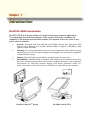
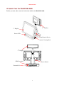
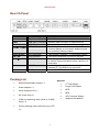
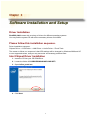
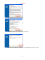
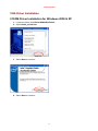
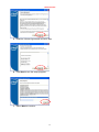
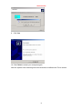
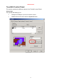
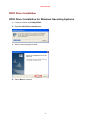
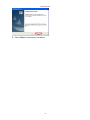
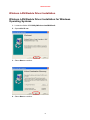
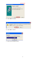
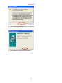
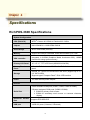
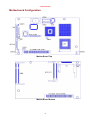
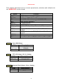
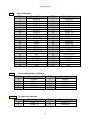
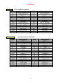
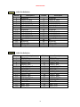
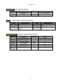
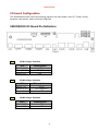
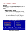
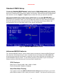
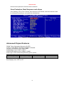
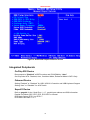
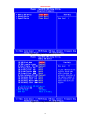
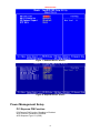
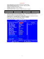
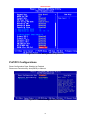
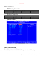
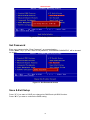
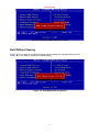
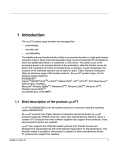
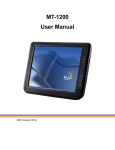
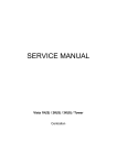
User's Manual
RichPOS 3600
12”/15”/17”
P4 High-Performance POS system
Copyright Notice
This document is copyrighted, © 2007. All rights are reserved. Firich Enterprise Co., Ltd reserves
the right to make improvements of the product described in this manual at any time without notice.
No part of this manual may be reproduced, copied, translated, or transmitted in any form or by
any means without the prior written permission from Firich Enterprise Co., Ltd. Information
provided in this manual is intended to be accurate and reliable. However, Firich Enterprise Co.,
Ltd assumes no responsibility for its use, nor for any infringements upon the rights of third parties,
which may result from its use.
The material in this document is for product information only and is subject to change without
notice. While reasonable efforts have been made in the preparation of this document to assure its
accuracy, Firich Enterprise Co., Ltd, assumes no liabilities resulting from errors or omissions in
this document, or from the use of the information contained herein.
Safety and Warranty
1. Read these safety instructions carefully.
2. Keep this user's manual for later reference.
3. Disconnect this equipment from any AC outlet before cleaning. Do not use liquid or spray
detergents for cleaning. Use a damp cloth.
4. For pluggable equipment, the power outlet must be installed near the equipment and must be
easily accessible.
5. Keep this equipment away from humidity.
6. Put this equipment on a reliable surface during installation. Dropping it or letting it fall could
cause damage.
7. The openings on the enclosure are for air convection. Protect the equipment from overheating.
DO NOT COVER THE OPENINGS.
8. Make sure the voltage of the power source is correct before connecting the equipment to the
power outlet.
9. Position the power cord so that people cannot step on it. Do not place anything over the power
cord.
10. All cautions and warnings on the equipment should be noted.
11. If the equipment is not used for a long time, disconnect it from the power source to avoid
damage by transient over-voltage.
12. Never pour any liquid into an opening. This could cause fire or electrical shock.
13. Never open the equipment. For safety reasons, only qualified service personnel should open
the equipment.
14. If any of the following situations arises, get the equipment checked by service personnel:
a. The power cord or plug is damaged.
b. Liquid has penetrated into the equipment.
c. The equipment has been exposed to moisture.
d. The equipment does not work well, or you cannot get it to work according to the user’s manual.
e. The equipment has been dropped and damaged.
f. The equipment has obvious signs of breakage.
15. DO NOT LEAVE THIS EQUIPMENT IN AN UNCONTROLLED ENVIRONMENT WHERE
THE STORAGE TEMPERATURE IS BELOW -20° C (-4°F) OR ABOVE 60° C (140° F). IT MAY
DAMAGE THE EQUIPMENT.
Table of Content
Chapter 1
Introduction
1
1
RichPOS-3600 Introduction................................................................................................... 1
A Quick Tour for RichPOS-3600 ........................................................................................... 2
RichPOS-3600 Dimension.............................................................................................. 3
Rear I/O Panel....................................................................................................................... 4
Packing List ........................................................................................................................... 4
Chapter 2
Hardware Installation and Upgrading
5
5
2.5” Hard Disk Drive Installation ..................................................................................... 5
2nd Display (LCD/VFD) Installation................................................................................ 6
Memory (DDRII RAM) / Compact Flash Card (CF) Installation ...................................... 7
MCR Parameter Modification ......................................................................................... 7
Cash Drawer Installation ................................................................................................ 8
Chapter 3
Software Installation and Setup
9
9
Driver Installation................................................................................................................... 9
Please follow this installation sequence. ............................................................................... 9
Intel Chipset Driver Installation.............................................................................................. 9
VGA Driver Installation ........................................................................................................ 11
915GM Driver Installation for Windows 2000 & XP ...................................................... 11
Enable Second LCD Panel Setting for Windows 2000 & XP........................................ 14
LAN Driver Installation......................................................................................................... 18
LAN Driver Installation for all Windows Operating Systems. ........................................ 18
Audio Driver Installation....................................................................................................... 20
Audio Driver Installation for all Windows Operating Systems....................................... 20
ELO Touch Tools Installation .............................................................................................. 22
ELO Touch Tools Installation for Windows 2000 and XP............................................. 22
ELO Control Panel........................................................................................................ 25
TouchKit Tools Installation .................................................................................................. 28
TouchKit Tools Installation for Windows Operating Systems ....................................... 28
TouchKit Control Panel................................................................................................. 31
RFID Driver Installation ....................................................................................................... 32
RFID Driver Installation for Windows Operating Systems ............................................ 32
Wireless LAN Module Driver Installation ............................................................................. 34
Wireless LAN Module Driver Installation for Windows Operating Systems .................. 34
Chapter 4
Specifications
37
37
RichPOS-3600 Specifications ............................................................................................. 37
Motherboard Configuration.................................................................................................. 39
I/O board Configuration ....................................................................................................... 45
9000CB2030 I/O Board Pin Definition .......................................................................... 45
Mother Board BIOS Setup (AWARD) .................................................................................. 47
Introduction................................................................................................................... 47
Entering Setup.............................................................................................................. 47
Standard CMOS Setup................................................................................................. 48
Advanced BIOS Features............................................................................................. 48
Advanced Chipset Features ......................................................................................... 49
Integrated Peripherals .................................................................................................. 50
Power Management Setup ........................................................................................... 52
PnP/PCI Configurations................................................................................................ 54
PC Health Status .......................................................................................................... 55
Load SetUp Defaults .................................................................................................... 55
Set Password ............................................................................................................... 56
Save & Exit Setup......................................................................................................... 56
Exit Without Saving ...................................................................................................... 57
Chapter 5
Troubleshooting
58
58
Touch Panel Does not Work......................................................................................... 58
ELO Touch Panel Cannot Calibrate Correctly.............................................................. 58
LAN is not functioning properly..................................................................................... 58
COM1, COM2, COM5, COM6 are not functioning properly ......................................... 59
Cash Drawer Port is not functioning properly ............................................................... 59
USB device is not functioning properly......................................................................... 59
RICHPOS-3600
Chapter 1
Introduction
RichPOS-3600 Introduction
RichPOS 3600 is a decent solution for high-performance-required application.
The integrated and modulized design of the system effectively increases the
reliability of the product and therefore makes it an optimal choice for retail or any
public service markets.
•
System: Equipped with Intel 915GM and ICH6M chipsets plus high-speed CPU
support (up to Pentium M 2.13GHz), RichPOS-3600 is capable of handling a high
capacity of data efficiently.
•
Housing: The strong aluminum housing not only dissipates the heat inside the system
but decreases the level of possible damage from dropping, also assuring the compliance
to EMI radiation testing.
•
Display: The LCD display can be tilted at multiple angles for ease of use.
•
Extensibility: RichPOS-3600 is designed with sufficient I/O interfaces which allow
the unit to extend its functionality with a variety of additional devices, such as Magnetic
Card Reader, 2nd VFD/LCD customer display, Cash drawer, Biometric reader (ex.:
finger print reader) and a wide selection of USB devices (all available upon request.)
RichPOS-3600 W/2nd display
RichPOS-3600 W/VFD
1
RICHPOS-3600
A Quick Tour for RichPOS-3600
Before you start, take a moment to become familiar with RichPOS-3600.
2nd Display
1st Display
Power LED
Identification Device
System Venting Hole
2nd Display
HDD Location
Power Button
External I/O
2
RICHPOS-3600
RichPOS-3600 Dimension
3
RICHPOS-3600
Rear I/O Panel
I/O Port
Connector Type
Description
Line Out
USB
Earphone connector
Connect the speakers to this port
USB type A connector Standard USB connector for external device
DC-in
COM5、COM6
DC Power connector
Connect the power adaptor to this port
VFD / RJ45 connector This RJ45 port can be used to attach a VFD
customer display or serve as an additional serial
port (switching cable provided).
Cash Drawer
KB / MS
COM1、COM2
RJ11 connector
PS2 connector
D-SUB 9 connector
Printer
SCSI Ribbon 26pin
LAN
RJ45 connector
Cash Drawer Connector, 12 V actuation support
Connect the keyboard or mouse to this port
The serial ports COM1/COM2/COM5/COM6 can
be used to connect devices such as a printer or a
fax/modem.
A switching cable provided to connect printer with
standard LPT (D-SUB 25 pin) connector.
Connect RichPOS-3600 to the Ethernet
Packing List
Optional:
•
RichPOS-3600 Main System x 1
•
2nd LCD Display
•
Power Adapter x 1
•
Finger Print Reader
•
Driver & Manual CD x 1
•
RFID
•
MCR
•
AC Power Cord x 1
•
VFD Customer Display
•
COM port switching cable (RJ45 to D-SUB
•
Wireless LAN Module
9 pin) x 2
•
Printer switching cable (SCSI 26 pin to LPT)
x1
4
RICHPOS-3600
Chapter 2
Hardware Installation and Upgrading
Do not remove the rear cover until you have verified that no power is
supplied to the system. Power must be switched off and the power cord
must be unplugged. Every time you service the system, you should be
aware of this.
2.5” Hard Disk Drive Installation
1. Turn off power and remove power cord from the system
2. Unscrew the HDD tray
at the bottom of the
unit
3. Pull the HDD tray out
5
RICHPOS-3600
4. Place HDD on the tray
with PCB side upward
(no screw needed).
2nd HDD
Position
1st HDD
Position
5. Slide in the HDD tray back to the system (no cabling needed).
7. Fix the HDD tray with the screw.
8. Connect the power cord to the system.
2nd Display (LCD/VFD) Installation
1. Remove the plastic
cover above the rear I/O
panel
6
RICHPOS-3600
2. Slide in the 2nd display
set and screw it on the
system (no cabling
needed)
Memory (DDRII RAM) / Compact Flash Card (CF) Installation
1.
Unscrew and remove
the bottom cover
2.
Install the DDRII RAM or CF you require
3.
Restore the bottom cover
MCR Parameter Modification
This option is for users who need to customize the MCR parameters for a particular task.
Some of the useful parameters include:
The selection of country code, other than the default English.
7
RICHPOS-3600
The choice of track combinations.
The preamble/post amble codes.
The MCR parameters can be modified by using the supplied utility program.
The utility can be found on the CD that came with your system in the “Utilities” folder. The
program name is msr_v12_win.zip.
Cash Drawer Installation
Before connecting the cash drawer to the RichPOS-3600, please make sure the drive voltage
and cable pin assignment of the cash drawer matches the definition of the cash drawer port of
RichPOS-3600. Please refer to page 46 for more information.
Plug cash drawer cable into the cash drawer port.
Note: If the cash drawer cannot be detected by the system, please refer to troubleshooting.
The default driving voltage of the solenoid is DC+12V. It can be adjusted to DC +5V by switching
the jumper setting on CN5. Please refer to page 46 for more information.
Two ports are used for drawer operation: 2Eh (index port) and 2Fh (data port). A test program is
supplied (\Utility\POS Utility\Cash Drawer\GPO\GPO0.exe). For Linux and Windows, source
code of which is available on request by software developers.
8
RICHPOS-3600
Chapter 3
Software Installation and Setup
Driver Installation
RichPOS-3600 comes with a variety of drivers for different operating systems.
You may find the system CD with all the necessary drivers and utilities.
Please follow this installation sequence.
Driver installation sequence:
Chipset Driver -> VGA Driver -> LAN Driver -> Audio Driver ->Touch Tools
The reason to follow our sequence is that IRQ settings will be changed by Windows 2000 and XP
to non supported values, and you may encounter unnecessary problems later.
Intel Chipset Driver Installation
1. Insert the CD into your CD ROM Drive.
2. Locate the folder of D:\DRIVER\WIN2K&XP\CHIPSET\
3. Open infinst_autol.exe
4. Click Next.
9
RICHPOS-3600
5. Read the License Agreement and click Yes.
6. Click Next and the drivers for the Intel Chip set will install.
7. When the 'Setup COMPLETE' message appears click Finish to restart your computer.
10
RICHPOS-3600
VGA Driver Installation
915GM Driver Installation for Windows 2000 & XP
1. Locate the folder of D:\Driver\WIN2K&XP\VGA\
2. Open win2k_xp1424.exe
3. Select Next to continue.
4. Select Next to continue.
11
RICHPOS-3600
5. Read the License Agreement and click Yes.
6. Click Next to see the setup progress.
7. Select Next to continue.
12
RICHPOS-3600
8. Click Finish to complete the installation procedure and restart the system.
13
RICHPOS-3600
Enable Second LCD Panel Setting for Windows 2000 & XP
After you have installed the VGA driver, you must adjust the settings as follows.
.
1. Right click your mouse anywhere on the desktop and then click properties.
2. Click the Settings tab.
14
RICHPOS-3600
3. Click Advanced.
4. Click Intel(R) Graphics Media Accelerator Driver for Mobile.
15
RICHPOS-3600
5. Click Graphics Properties.
6. Click Extended Desktop and select Notebook for primary device, monitor for secondary
device.
16
RICHPOS-3600
7. Click OK.
8. Select the second LCD panel. This is done either by clicking on the number 2 or selecting
from the dropdown menu.
For the second LCD panel make sure that Extend my Windows desktop onto this monitor
is selected.
9. Click Apply then click OK to finish the settings.
Note. During boot sequence “No Sync” will appear on the second LCD panel.
The boot sequence can take a minute or so when a second LCD panel is installed.
17
RICHPOS-3600
LAN Driver Installation
LAN Driver Installation for all Windows Operating Systems.
1. Locate D:\Driver\WIN2K&XP\LAN\RTL8111B\
2. Double click Setup.exe.
3. Click Next to continue
18
RICHPOS-3600
4. Click Next to continue
5. Click Finish to complete the installation procedure.
19
RICHPOS-3600
Audio Driver Installation
Audio Driver Installation for all Windows Operating Systems.
1. Locate D:\Driver\WIN2K&XP\AC97\ WDM_A391\
2. Double click Setup.exe.
Note: If you receive this warning message, please click Continue Anyway to proceed.
20
RICHPOS-3600
3. Click Finish and restart the system.
21
RICHPOS-3600
ELO Touch Tools Installation
ELO Touch Tools Installation for Windows 2000 and XP
1. Locate D:\Utility\TOUCHSCREEN\ELO Touch
2. Select the relevant ELO folder for the operating system that you are using.
Example. If you are installing for a Windows 2000 or XP then select Elo Touch 2K_XP
3. Open Setup.exe
4. Click Next
5. Check “Install serial Touch screen Drivers.” And Click Next.
22
RICHPOS-3600
6. Read the “License Agreement” and click Yes if you accept it.
7. Select “Auto-detect Elo devices” and click Next.
8. Select the COM port for the touch monitor. It is recommended that you select COM3 for
the touch screen, as this port is internally configured for touch operation.
9. Wait until the ELO Touch Tools have been installed.
23
RICHPOS-3600
10. Select “View ELO touch screen control panel” and click Finish.
IT MAY BE NECESSARY TO RESTART YOUR COMPUTER TO UTILIZE
YOUR TOUCHSCREEN FEATURES.
11. Click NEXT while this window appears after system finish rebooting.
12. Click YES to restart your computer again.
After the system finish rebooting follow the directions to calibrate ELO Touch Tools.
24
RICHPOS-3600
ELO Control Panel
This section explains the different options in the ELO control Panel.
General tab
The general tab allows you to:
•
Change the COM port your touch screen is set to.
•
Calibrate the touch screen with the Align button.
25
RICHPOS-3600
Mode tab
The Buttons tab allows you to:
•
Adjust all mouse emulation controls.
•
Change cursor properties
•
Enable or disable right mouse button utility.
Sound tab
The Sound tab allows you to:
•
To change sound properties for ELO touch tools.
26
RICHPOS-3600
Properties tab
The Diagnostics tab allows you to:
•
View Controller Information.
About tab
The About tab displays Information about ELO Touch systems
27
RICHPOS-3600
TouchKit Tools Installation
TouchKit Tools Installation for Windows Operating Systems
1. Locate D:\Utility\TOUCHSCREEN\TouchKit(Fujitsu)\Driver
2. Select the relevant folder for the operating system that you are using.
3. Open Setup.exe
4. Click Next
5. Click Next
28
RICHPOS-3600
6. Click Next
7. Click Next
8. Click Next
29
RICHPOS-3600
9. Click Yes
10. Click Finish to restart your computer again.
After the system finish rebooting follow the directions to calibrate the Touch screen.
30
RICHPOS-3600
TouchKit Control Panel
This section explains the different options in the TouchKit control Panel.
General tab
The general tab allows you to:
•
Change the COM port your touch screen is set to.
•
Calibrate the touch screen with the 4 pts Cal button.
31
RICHPOS-3600
RFID Driver Installation
RFID Driver Installation for Windows Operating Systems
1. Locate the folder of D:\Utility\RFID\
2. Open PL-2303 Driver Installer.exe
3. Wait for the next page to show
4. Select Next to continue
32
RICHPOS-3600
5. Select Finish to complete the installation
33
RICHPOS-3600
Wireless LAN Module Driver Installation
Wireless LAN Module Driver Installation for Windows
Operating Systems
1. Locate the folder of D:\Utility\Wireless Lan\WinBond\
2. Open w89c35.exe
3. Select Next to continue
4. Select Next to continue
34
RICHPOS-3600
5. Select Next to continue
6. Select OK to continue
7. Wait for the next page to show
35
RICHPOS-3600
8. Select Continue Anyway to go to the next step
9. Select Finish to complete the installation
36
RICHPOS-3600
Chapter 4
Specifications
RichPOS-3600 Specifications
System Configuration
CPU (PGA 478)
INTEL® Celeron M 1.5GHz or Pentium M 2.13GHz
Chipset
i82915GM MCH + i82801FBM ICH6-M
South Bridge
INTEL 82801FBM (ICH6-M)
Memory
Support one 200-pin SODIMM, DDRII 400/533MHz up to 1GB
VGA controller
Integrated in 915GM (Graphics Media Accelerator 900). 128MB
frame buffer using system memory
Primary LCD Panel
12” /15” /17” TFT LCD Panel (800X600/1024x768).
Primary Touch
Panel
12” with ELO 4-wire or 15”/17” with ELO 5-wire resistive touch
panel.
Storage
Internal 2.5” Serial ATA 40GB hard disk drive (support up to 2 x
2.5” SATA HDD)
Supports type II Compact Flash™ Disk. IDE interface
Power
150 watt external power adapter.
I/O Port
Serial Port
4 User available COM ports (COM1, COM2, COM5 & COM6).
2 System assigned COM ports (COM3 & COM4).
¾ COM3 for primary touch screen.
¾ COM4 for secondary touch screen or customer character
display.
Enhanced Parallel
Port
supports EPP/SPP/ECP
USB port
4 USB 2.0 ports (2*Internal, 2*External)
37
RICHPOS-3600
Cash drawer port
RJ11 Cash drawer port,12V actuation. Controlled through 2Eh
(index port) and 2Fh (data port)
Keyboard Port
One PS/2 keyboard port.
LAN Port
10/100/1000Base-T Ethernet Controller, Realtek RTL8111B
Specially designed connection port for
FEC VFD or 2nd LCD display (not
standard D-SUB VGA port)
2nd Display
Connection
Audio Port
Integrated Sound Blaster compatible, AC97 Audio Codec. (Realtek
ALC655)
Expansion
One mini-PCI socket available
Optional Features
Customer display
Integrated VFD/LCD customer display.
MSR
External Magnetic Stripe Card Reader track 1/2/3
Identification
Device
External Finger Print Receiver and RFID receiver(USB)
Wireless
Internal Wireless Module(USB)
Power Consumption
Power
consumption
80W Idle
(Standard system with secondary LCD panel while accessing
HDD).
Operating temperature
Operating
temperature
0 ℃ ~ 40 ℃
38
RICHPOS-3600
Motherboard Configuration
Mother Board Top
Mother Board Bottom
39
RICHPOS-3600
This chapter describes how to connect peripherals, switches and indicators to
the AIMB-553 mother board.
Label
JCMOS1
JLVD1
JIDESET1
IDE1
USB1
TVOUT1
SEC_VGA1
FIVE_IN_ONE1
LVDS36
LVDS48
SYSFAN1
SYSFAN2
BTN1
JCMOS1
CMOS clear
Set Panel Voltage to 3.3V or 5.0V
Set Compact Flash Master / Slave
44pin 2.0mm Connector, support 2.5” IDE HDD
USB 2.0 port 4 and port 5
TV output function
VGA & COM4
COM3, USB 2.0 port6, port7, inverter, K/B pass, speaker
out
Integrated Flat Panel interface, 18bits / 36bits Dual
Channel
Flat Panel interface by SDVO_B, 24bits / 48bits Dual
Channel
FAN connector
FAN connector
Power Button, Power LED, Reset Button, KB Lock, PS-on
Clear CMOS Setup
PIN
Short 1-2*
Short 2-3
JLVD1
Function
Description
Keep CMOS Setup
(Default)
Clear CMOS Setup
TFT LCD Voltage ( 5V / 3V ) Setting
PIN
Short 1–2
Short 2–3
Description
3.3V TFT LCD
5V TFT LCD
JIDESET1 Compact Flash ( Master / Slave ) Setting
PIN
Short 1–2
Short 2–3
Description
CF Master
CF Slave
40
RICHPOS-3600
IDE1
IDE Pin Definition
PIN
1
3
5
7
9
11
13
15
17
19
21
23
25
27
29
31
33
35
37
39
41
43
USB1
PIN
2
4
6
8
10
12
14
16
18
20
22
24
26
28
30
32
34
36
38
40
42
44
Description
GROUND
DATA 8
DATA 9
DATA 10
DATA 11
DATA 12
DATA 13
DATA 14
DATA 15
N/C
GROUND
GROUND
GROUND
REV. PULL LOW
GROUND
N/C
PD66 SELECT
SA2
HDC CS1#
GROUND
+5V
N/C
2 Ports USB Definition (USB 2.0)
PIN
1
3
5
7
9
TVOUT1
Description
RESET#
DATA 7
DATA 6
DATA 5
DATA 4
DATA 3
DATA 2
DATA 1
DATA 0
GROUND
DRQ
IOW#
IOR#
CHRDY
DACK
INTERRUPT
SA1
SA0
HDC CS0#
HDD ACTIVE#
+5V
GND
Description
USBV3
USBD4USBD4+
GROUND
GROUND
PIN
2
4
6
8
10
Description
USBV3
USBD5USBD5+
GROUND
GROUND
PIN
2
4
Description
TVDAC_B
GROUND
TV Output Pin Definition
PIN
1
3
Description
TVDAC_A
TVDAC_C
41
RICHPOS-3600
SEC_VGA1
VGA & COM4 Pin Definition
PIN
1
3
5
7
9
11
13
15
17
19
21
23
25
FIVE_IN_ONE1
PIN
1
3
5
7
9
11
13
15
17
19
21
23
25
27
29
31
33
Description
VCC12-IO(12V)
RID#4
DTRD#4
SOUTD
RTSD#4
GROUND
VCC12-IO(12V)
VCC12-IO(12V)
VGA_RED
VGA_GREEN
VGA_BLUE
VGA_Hsync
VGA_Vsync
PIN
2
4
6
8
10
12
14
16
18
20
22
24
26
Description
VCC12-IO(5V)
DSRD#4
SIND
DCDD#4
CTSD#4
GROUND
VCC12-IO(12V)
VGA_SMDAT
VGA_SMCLK
GROUND
GROUND
GROUND
GROUND
34Pin Box Header Pin Definition
Description
DCDC#3
SINC
SOUTC
DTRC#3
GROUND
USBV4
USB6+
USBV4
USB7+
VCC12_INV1 (12V)
GROUND
BKLT_EN
SIO_KBDAT
SIO_KBCLK
AUD_GND
AUD_GND
GROUND
PIN
2
4
6
8
10
12
14
16
18
20
22
24
26
28
30
32
34
42
Description
DSRC#3
RTSC#3
CTSC#3
RIC#3
VCC_COM3 (5V)
USB6GROUND
USB7GROUND
VCC12_INV1 (12V)
GROUND
VCC_KB (5V)
KB_DAT
KB_CLK
SPKOUT-R
SPKOUT-L
GROUND
RICHPOS-3600
LVDS36
LVDS Pin Definition
PIN No.
1
3
5
7
9
11
13
15
17
19
21
23
25
27
29
LVDS48
Description
PIN No.
GROUND
LVDS_A_D0P
LVDS_A_D1P
LVDS_A_D2P
LVDS_A_CLKP
NC
GROUND
LVDS_B_D0P
LVDS_B_D1P
LVDS_B_D2P
LVDS_B_CLKP
NC
GROUND
VDD_LCD
VDD_LCD
2
4
6
8
10
12
14
16
18
20
22
24
26
28
30
Description
GROUND
LVDS_A_D0P
LVDS_A_D1P
LVDS_A_D2P
LVDS_A_CLKP
NC
GROUND
LVDS_B_D0P
LVDS_B_D1P
LVDS_B_D2P
LVDS_B_CLKP
NC
GROUND
VDD_LCD
VDD_LCD
LVDS Pin Definition
PIN No.
1
3
5
7
9
11
13
15
17
19
21
23
25
27
29
Description
PIN No.
GROUND
LVDS2_A0P
LVDS2_A1P
LVDS2_A2P
LVDS2_CLK1P
LVDS2_A3P
GROUND
LVDS2_A4P
LVDS2_A5P
LVDS2_A6P
LVDS2_CLK2P
LVDS2_A7P
GROUND
VDD_LCD
VDD_LCD
2
4
6
8
10
12
14
16
18
20
22
24
26
28
30
43
Description
GROUND
LVDS2_A0P
LVDS2_A1P
LVDS2_A2P
LVDS2_CLK1N
LVDS2_A3N
GROUND
LVDS2_A4N
LVDS2_A5N
LVDS2_A6N
LVDS2_CLK2N
LVDS2_A7N
GROUND
VDD_LCD
VDD_LCD
RICHPOS-3600
SYSFAN1 & 2 Fan Connectors Definition
PIN
1
3
BTN1
Description
GROUND
SPEED
PIN
2
Description
12V(or Pulse)
Power Switch & LED Function Setting
PIN
Short 1–2
Short 3–4
Short 5-6
Description
ATX Soft power switch
Power LED
CPU Reset Bottom or
switch
PIN
Short 7-8
Short 9-10
Short 11-12
Description
HDD LED
Keyboard Lock
PS-ON
COM & PARALLEL COM Ports & Parallel Port Definition
COM Port
COM1
COM2
COM3
COM4
COM5
COM6
Parallel
Port
Location
IO_FINGER1
IO_FINGER1
FIVE_IN_ONE1
SEC_VGA1
IO_FINGER1
IO_FINGER1
IO_FINGER1
Address
3F8
2F8
4E0
4E8
4F0
4F8
378
44
IRQ
4
3
10
11
5
11
7
RICHPOS-3600
I/O board Configuration
The 9000CB2030 board carries the following signals to the main board: LAN, LPT, COM (1/2/5/6),
keyboard, cash drawer, audio in and two USB ports.
9000CB2030 I/O Board Pin Definition
JP1
COM1 Voltage Selection
JP1
Short 1-2
Short 3-4*
Short 5-6
JP1
COM2 Voltage Selection
JP1
Short 7-8
Short 9-10*
Short 11-12
CN2
Description
+12V
RI (Default)
+5V
Description
+12V
RI (Default)
+5V
COM5 Voltage Selection
CN2
Short 1-2
Short 2-3
Description
+12V
+5V
45
RICHPOS-3600
CN1
COM5 Mode Selection
CN1
Short 1-3
Short 2-4
Short 1-2
Short 3-5
Short 4-6
CN4
VFD
Description
+12V
+5V
COM6 Mode Selection
CN3
Short 1-3
Short 2-4
Short 1-2
Short 3-5
Short 4-6
CN5
RS-232 (Default)
COM6 Voltage Selection
CN4
Short 1-2
Short 2-3
CN3
Description
Description
RS-232 (Default)
VFD
Cash Drawer Voltage Selection
CN5
Short 1-2
Short 2-3*
Description
+5V
+12V (Default)
46
RICHPOS-3600
Mother Board BIOS Setup (AWARD)
Introduction
Award’s BIOS ROM has a built-in setup program that allows users to modify the
basic system configuration. This type of information is stored in battery backed-up
memory (CMOS RAM) so that it retains the setup information when the power is
turned off.
CMOS RAM Auto-backup and Restore
The CMOS RAM is powered by an onboard button cell battery. When you finish BIOS
setup, the data in CMOS RAM will be automatically backed up to Flash ROM. If operation
in harsh industrial environments causes a soft error, BIOS will recheck the data in CMOS
RAM and automatically restore the original data in Flash ROM to CMOS RAM for booting.
Note: If you intend to change the CMOS setting without restoring the previous backup,
you have to click on "DEL" within two seconds of the "CMOS checksum error..."
display screen message appearing. Then enter the "Setup" screen to modify the
data. If the "CMOS checksum error..."message appears again and again, please
check to see if you need to replace the battery in your system.
Entering Setup
Turn on the computer and press <Del> to allow you to enter the BIOS CMOS setup utility.
Figure 1: Award BIOS initial setup screen
47
RICHPOS-3600
Standard CMOS Setup
Choose the “Standard CMOS Features” option from the “initial setup screen” menu, and the
screen below will be displayed. This menu allows users to configure system components such as
date, time, hard disk drive, floppy drive, display, and memory. Use the arrow keys to highlight the
item and then use the <PgUp> or <PgDn> keys to select the value you want for each item.
IDE Channel 0 Master/Slave & IDE Channel 1 Master/Slave: If you select IDE HDD AutoDetection, BIOS will show the detail specifications of your drive automatically. If your hard disk
drive type is not matched or listed, you can use Manual to define your own drive type manually.
Enter the information directly from the keyboard. This information should be provided in the
documentation from your hard disk vendor or the system manufacturer.
Figure 2: Standard CMOS Features Screen
Advanced BIOS Features
The “Advanced BIOS Features” screen appears when choosing the “Advanced BIOS Features”
item from the “Initial Setup Screen” menu. It allows the user to configure the M/B (AIMB-553)
according to his particular requirements. Below are some major items that are provided in the
Advanced BIOS Features screen. A quick booting function is provided for your convenience.
Simply enable the Quick Booting item to save yourself valuable time.
CPU Features
Delay Prior to Thermal: 4Min, 8Min, 16Min or 32Min
Execute Disable Bit: Enabled or Disabled
Hard Disk Boot Priority
If you prefer to enter into HDD First Boot Device setting directly as Figure 2, you could
press <F11> instead of <Del> when you power on system. Pop-up menu will show you a
48
RICHPOS-3600
devices list as options for first boot device selection.
Virus Protection, Boot Sequence and others
Virus Warning, CPU L1 & L2 Cache, boot sequence, APIC Mode, and other features could
be configured according to your particular requirements.
Figure 3: Advanced BIOS Features Screen
Advanced Chipset Features
DRAM Timing Selectable: Manual or By SPD
System / Video BIOS Cacheable: Disabled or Enabled
On-Chip Frame Buffer Size: 1MB or 8MB
DVMT Mode: Fixed, DVMT or BOTH
DVMT/FIXED Memory Size: 64MB or 128MB
Panel Type: There are following different type for options
Table: Panel Type for Options
640x480 LVDS
800x600 LVDS
1400x1050 RB LVDS 1400x1050 Non-RB
1024x768 LVDS
1600x1200 LVDS
Boot Display: Auto, CRT or LFP
49
1280x1024 LVDS
RICHPOS-3600
Figure 4: Advanced Chipset Features Screen
Integrated Peripherals
OnChip IDE Device
Recommend to “Enabled” all IDE functions and PIO/UDMA by “Auto”
On-Chip Serial ATA: Disabled, Auto, Combined Mode, Enhanced Mode & SATA Only
Onboard Device
Setting “Enabled” or “Disabled” for USB / USB 2.0 Controller and USB Keyboard Support
Setting “Auto” or “Disabled” for AC97 Audio
SuperIO Device
Refer to page 44 for the “Serial Port 1 ~ 6” , parallel port address and IRQ information
Parallel Port Mode: SPP, EPP, ECP, ECP+EPP or Normal
ECP Mode Select: EPP1.9 or EPP1.7
ECP Mode Use DMA: 1 or 3
50
RICHPOS-3600
Figure 5: Integrated Peripherals Screen
Figure 6: OnChip IDE Device Screen
51
RICHPOS-3600
Figure 7: Onboard Device Screen
Figure 8: SuperIO Device Screen
Power Management Setup
PCI Express PM Function
PCI Express PM Function: Disabled or Enabled
ACPI Function: Disabled or Enabled
ACPI Suspend Type: S1 (POS)
52
RICHPOS-3600
Power Management: User Define, Min Saving or Max Saving
Video Off Method: Blank Screen, V/H SYNC + Blank or DPMS
Video Off In Suspend: No or Yes
Suspend Type: Stop or PwrOn Suspend
MODEM Use IRQ: NA, 3, 4, 5, 7, 9, 10 or 11
Suspend Mode: There are different mode as following for options
Table: Different Suspend Mode for options
Disabled
1 ~ 2 Min
8 ~ 10 Min
12 ~ 14 Min
2 ~ 3 Min
20 ~ 22 Min
4 ~ 6 Min
30 ~ 33 Min
HDD Power Down: There are Disabled or 1 Min ~ 7 Min different timing for options
Soft-Off by PWR-BTTN: Instant-Off or Delay 4 Sec.
PowerOn by LAN, PowerON by Modem and PowerOn by Alarm: Disabled or Enabled
Primary IDE 0 / 1, Secondary IDE 0 / 1: Disabled or Enabled
FDD, COM, LPT Port, PCI PIRQ[A-D]#: Disabled or Enabled
PWRON After PWR-Fail: Off, On or Former-Sts
Figure 9-1: Power Management Setup Screen
53
RICHPOS-3600
Figure 9-2: Power Management Setup Screen
PnP/PCI Configurations
Reset Configuration Data: Disabled or Enabled
Resources Controlled By: Auto(ESCD) or Manual
Figure 10: PnP/PCI Configurations Screen
54
RICHPOS-3600
PC Health Status
CPU Warning Temperature
Table: Different CPU Warning Temperature for options
Disabled
50℃/122℉
53℃/127℉
60℃/140℉
63℃/145℉
66℃/151℉
56℃/133℉
70℃/158℉
Shutdown Temperature
Table: Different Shutdown Temperature for options
Disabled
60℃/140℉
65℃/149℉
75℃/167℉
80℃/176℉
85℃/185℉
70℃/158℉
90℃/194℉
FAN Duty Control
There are four options as Full, 100%, 50% and 25%
Figure 11: PC Health Status Screen
Load SetUp Defaults
Press “Y” if you want to load BIOS default setting
Press “N” if you don’t want to load BIOS default setting and continue the BIOS setting
55
RICHPOS-3600
Figure 12: Load SetUp Defaults Screen
Set Password
Enter your password after “Enter Password:” as screen showing
Press “Enter” key if you don’t want to set password, “PASSWORD DISABLED!!!” will be showed
on screen.
Figure 13: Set Password Screen
Save & Exit Setup
Press “Y” if you want to SAVE your changed to CMOS and quit BIOS function.
Press “N” if you want to continue the BIOS setting.
56
RICHPOS-3600
Figure 14: Save to CMOS and EXIT Screen
Exit Without Saving
Press “Y” if you want to quit BIOS function without saving any changes which you did.
Press “N” if you want to continue the BIOS setting.
Figure 15: Quit Without Saving Screen
57
RICHPOS-3600
Chapter 5
Troubleshooting
Please note that the following troubleshooting guide is designed for people with strong computer
hardware knowledge such as System Administrators and Engineers.
Touch Panel Does not Work
A)
Check CMOS settings, COM3 needs to be “Enabled”. The correct settings are “4E0” and
“IRQ10”.
B)
Check if there are no conflicts between COM3 IRQ10 and any other devices.
C)
Check if the ELO driver or the TouchKit driver has been properly installed. Or try to reinstall again (Please refer to the ELO driver installation or the TouchKit driver).
D)
Check if the ELO controller or the TouchKit driver on COM3 has been detected during
the ELO driver or the TouchKit driver installation. If yes, then check if the flat cable from
the ELO touch screen or the TOUCHKIT touch screen has been properly connected to
the ELO controller or the TouchKit controller (Attention: Pin1 mark should be on the
same side as the ELO controller).
E)
Check if the ELO controller Green LED is blinking?
If no, there is no DC+5V support for the ELO controller from the motherboard.
F)
Touch screen controller could be defective or the touch panel could be defective.
ELO Touch Panel Cannot Calibrate Correctly
A)
Please replace the ELO controller, and re-calibrate. If this works, change back to the
original ELO controller, and re-calibrate.
B)
If the ELO touch panel still cannot calibrate correctly after changing to a new ELO
controller, the touch panel may be not installed properly or it could be defective.
LAN is not functioning properly
A)
Check if the LAN driver is installed properly. (Please refer to the LAN driver installation)
B)
Check if there are any IRQ conflicts.
C)
Check if the RJ45 cable is properly connected.
D)
The on board LAN chip could be defective.
58
RICHPOS-3600
COM1, COM2, COM5, COM6 are not functioning properly
A)
Check if the I/O ports are enabled in the CMOS setup.
B)
Check if there are any IRQ conflicts.
C)
The motherboard could be defective.
Cash Drawer Port is not functioning properly
A)
Make sure the pin assignment matches between the cash drawer and the RJ11 cash
drawer port.
B)
Verify the digit I/O port address and bit are 2Eh (index port) and 2Fh (data port)
respectively.
C)
The motherboard could be defective.
USB device is not functioning properly
A)
Ensure that the USB controller is “enabled” in the CMOS setup.
B)
Ensure that the USB Legacy is “enabled” in the CMOS setup. (Windows 2000、Window
XP Professional)
C)
Ensure that the USB Legacy is “Disabled” in the CMOS setup. (Embedded OS:
Windows XP Embedded、Window CE. NET、Linux RedHat 9)
59