1
MSC PC/104
STPC Atlas
User's Manual
Version 0.2
09 / 12 / 2003
MSC Vertriebs GmbH
Design Center Neufahrn
PC104 STPC Atlas User's Manual
Copyright Notice
This document is copyrighted, 2003, by MSC Vertriebs GmbH. All rights are
reserved. MSC Vertriebs GmbH reserves the right to make improvements to the
products described in this manual at any time without notice.
No part of this manual may be reproduced, copied, translated or transmitted in
any form or by any means without the prior written permission of MSC Vertriebs
GmbH.
Information provided in this manual is intended to be accurate and reliable. However, MSC Vertriebs GmbH assumes no responsibility for its use, nor
for any infringements upon the rights of third parties which may result from its
use.
* Important Information
This product is not an end user product. It was developed and manufactured for further processing by trained personnel.
EMC Rules
This unit has to be installed in a shielded housing. If not installed in a
properly shielded enclosure, and used in accordance with the instruction
manual, this product may cause radio interference in which case the
user may be required to take adequate measures at his or her own expense.
2
PC104 STPC Atlas User's Manual
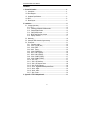
Contents
1. General Information......................................................................................... 4
1.1. Introduction ............................................................................................... 4
1.2. Block Diagram............................................................................................ 5
1.3. Hardware Specifications ........................................................................... 6
1.4. BIOS .......................................................................................................... 8
1.5. Board Layout............................................................................................. 9
2. Installation ........................................................................................................ 11
2.1. Jumpers (overview)................................................................................... 11
2.1.1. CPU .................................................................................................. 12
2.1.2. Installing a DRAM SO-DIMM module .............................................. 13
2.1.3. CompactFlash Socket...................................................................... 14
2.1.4. Clear CMOS Jumper ....................................................................... 15
2.1.5. BIOS Flash Recovery Jumper ......................................................... 16
2.1.6. Display Interface ............................................................................. 17
2.2. Watchdog.................................................................................................. 18
2.3. Interrupts, DMA channels, Upper memory................................................ 20
2.4. Connectors................................................................................................ 21
2.4.1. Connector types............................................................................... 22
2.4.2. X1201 PC/104 (ISA) ....................................................................... 23
2.4.3. X1203 EIDE.................................................................................... 24
2.4.4. X1001 Floppy................................................................................... 25
2.4.5. X1004 Parallel Port......................................................................... 26
2.4.6. X601 COM 1 (RS232) .................................................................... 26
2.4.7. X602 COM 2 (RS232) .................................................................... 26
2.4.8. X1001 COM 3 (RS232) .................................................................. 27
2.4.9. X1002 COM 4 (RS232) .................................................................. 27
2.4.10. X501 CRT..................................................................................... 27
2.4.11. X503 LCD Interface ...................................................................... 28
2.4.12. X502 LCD Inverter Power............................................................. 28
2.4.13. X901 RJ45 (Ethernet)................................................................... 29
2.4.14. X1102 Keyboard/Mouse/Speaker/Reset ...................................... 29
2.4.15. X401a USB0................................................................................. 30
2.4.16. X401b USB1................................................................................. 30
2.4.17. X801 Power .................................................................................. 30
3. Appendix : STPCA Adapterboard................................................................... 31
3
PC104 STPC Atlas User's Manual
1. General Information
1.1. Introduction
The PC/104 STPC Atlas is an all-in-one single board computer card for the
PC/104 bus .
With an onboard LCD/CRT SVGA controller and an 100BaseT Ethernet controller, the PC/104 STPC Atlas packs all the functions of an industrial computer and
its display capabilities onto a single card. This makes the PC/104 STPC Atlas an
ideal solution for embedded applications.
The PC/104 STPC Atlas is based on the STPC Atlas processor of ST Microelectronics.
The PC/104 STPC Atlas supports 3,3V SDRAM. It provides a 144-pin standard
SO-DIMM socket giving you the flexibility to configure your system with up to 128
MB SDRAM memory.
The integrated flat panel/CRT SVGA controller shares up to 4 MByte Video Memory (UMA) with the CPU. The CRT Controller has a 135MHz RAMDAC . The
flat panel controller can directly drive TFT displays.
Another onboard device is the 100MBit PCI Ethernet controller (82551ER).
The PC/104 STPC Atlas includes an IDE controller (44pin, 2mm connector) and
a floppy interface (26pin FFC connector) .
A CompactFlash socket (solder side) is provided .
Onboard features include four RS-232 serial ports, two USB 1.1 ports, one bidirectional SPP/EPP/ECP parallel port and a PS/2 keyboard/mouse interface.
The real time clock is buffered by a removable lithium battery.
4
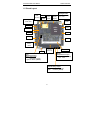
5
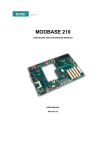
PC/104 STPC ATLAS 133MHz
WDGRESET
PC104
Connector
RTC
Lithium
Battery
ISA BUS
USB
2x5pol
2,54mm
Compact Flash
CF 50pol
EIDE
44pol 2,0mm
WDGRESET
Super I/O
WINBOND
W83977EF
COM4
10pol
2,54mm
Power-In 5V
FD 4pol
Power
Reset
In: 5V
Out: 2,5V; 3,3V;
BIOS Flash
ATLAS 133 MHz
STPC
Keyb. / Reset/
Speaker
2x5pol 2,54mm
COM3
10pol
2,54mm
Strapping
Memory
CRT
Interface
2x5pol 2,54mm
LPT1
DRAM
144pin
SO-DIMM
TFT
Digital Interface
2x17pol 2,0mm
COM2
10pol
2,54mm
PCI BUS
Backlight
3 pol
2,54mm
COM1
10pol
2,54mm
LAN Controller
10/100MBit
Intel 82551ER
10 pol
2,54mm
PC104 STPC Atlas User's Manual
General Information
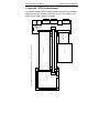
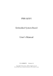
1.2. Block Diagram
Floppy
FFC26
PC104 STPC Atlas User's Manual
General Information
1.3. Hardware Specifications
Enhanced x86 CPU with 64 bit local bus
8Kbyte data cache (write back)
Clock core speed 133 MHz
2,5V core power supply
Integrated 64 bit DRAM Controller
Integrated SVGA Graphics Controller
UMA Architecture
CRT Controller ,135MHz RAMDAC
TFT Display Controller
Digital interface 18 Bit
Serial interfaces COM1/2, RS232
2 USB 1.1 ports
Integrated standard PC/AT keyboard controller
144pin 64bit SO-DIMM socket (up to 128 MByte SD RAM)
ISA Bus for PC/104 standard
10/100 MBit Ethernet Controller (RJ45 Interface)
Super-I/O (W83977EF)
IDE master/slave interface für HDD and/or CD-ROM
Floppy Disk Interface
Serial interfaces COM3/4, RS232
Parallel interface LPT1
Watchdog
Reset Controller
Real Time Clock with removable Lithium battery ("Snap Hat")
FlashBIOS
Single 5 V power supply
CompactFlash socket
6
PC104 STPC Atlas User's Manual
General Information
Connectors for
•
•
•
•
•
•
•
•
•
•
•
•
•
•
•
PC/104 ISA bus
IDE
Floppy
COM1 (RS232)
COM2 (RS232)
COM3 (RS232)
COM4 (RS232)
LPT1 (Centronics)
USB (1/2)
PS/2 keyboard, PS/2 mouse, Speaker, Reset
CRT
TFT (Digital interface)
LCD Inverter Power
RJ45 Ethernet
Power Supply
Power supply:
+5V ±5%
+12V ±5%
required for PC/104 modules only
Supply current (typ.) :
+5V
1A
+12V
133 MHz CPU
depends on PC/104 modules
Environment:
Temperature
operating
non operating
0 .. + 60°C
-25 .. + 85°C
Humidity (rel.)
operating
non operating
20 - 80 %
5 - 95 %
Dimensions:
90 x 96 mm
115,4 x 96 mm (connector area)
7
PC104 STPC Atlas User's Manual
General Information
1.4. BIOS
PhoenixBIOS 4.0:
•
Plug & Play (PCI, ISA)
•
PCI Auto Konfiguration (PCI 2.1)
•
Advanced Power Management 1.2
•
BIOS Update via floppy incl. Crisis Recovery in case of a
damaged system BIOS
•
Quick Boot
•
System and Setup Password
8
PC104 STPC Atlas User's Manual
General Information
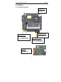
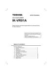
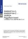
1.5. Board Layout
Ethernet
RJ45
(PCI bus)
Floppy
(solder side)
CRT
USB1
USB0
1
1
1
5
5
1
Real
Time
Clock
TFT
Display
(digital)
Backlight
Power
123
1
1
1
1
STPC
Atlas
CPU
1
IDE
1
COM 2
COM 1
LJP504
Backlight Power
1-2 : +5V (default)
2-3 : +12V
1
COM 3
1
COM 4
1
LPT
1
Keyboard,
Mouse,
Reset
1
Power
PC/104
(ISA bus)
SO-DIMM
JP1201
CompactFlash Jumper
installed: Master (default)
open: Slave
JP701
CMOS Clear Jumper
installed: CMOS Clear
(Setup Data cleared)
open: no action, (default)
JP601
BIOS Recovery Jumper
installed: BIOS recovery mode
open:
no action, (default)
9
PC104 STPC Atlas User's Manual
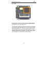
LJP501
VCC Display
1-2 : +5V
2-3 : +3,3V (default)
Installation
CompactFlash
1
2
3
10
Floppy
PC104 STPC Atlas User's Manual
Installation
2. Installation
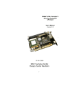
2.1. Jumpers (overview)
LJP504
Backlight Power
1-2 : +5V (default)
2-3 : +12V
1
1
5
5
1
123
1
STPC
Atlas
CPU
1
1
JP701
CMOS Clear Jumper
installed: CMOS Clear
(Setup Data cleared)
open: no action, (default)
LJP501
VCC Display
1-2 : +5V
2-3 : +3,3V (default)
JP1201
CompactFlash Jumper
installed: Master (default)
open: Slave
JP601
BIOS Recovery Jumper
installed: BIOS recovery mode
open:
no action, (default)
1
2
3
11
PC104 STPC Atlas User's Manual
Installation
2.1.1. CPU
The PC/104 STPC Atlas CPU card is based on the STPC Atlas CPU
from ST Microelectronics. The processor runs at 133 MHz (100MHz
Front Side Bus) with a core voltage of 2.5 V .
The STPC Atlas integrates a fully static x86 processor, fully compatible
with standard fifth generation x86 processors, and combines it with powerful chipset, graphics, TFT, PC-Card, Local Bus, keyboard, mouse,
serial and parallel interfaces to provide a single industrial oriented PC
compatible subsystem on a single device. The performance is comparable with the performance of a typical P5 generation system. The device is packaged in a 516 Plastic Ball Grid Array (PBGA).
12
PC104 STPC Atlas User's Manual
Installation
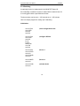
2.1.2. Installing a DRAM SO-DIMM module
The PC/104 STPC Atlas board has a SO-DIMM socket for standard 3,3V
SDRAM SO-DIMM modules :
26,67 mm max !
Module organization
Capacity
4M x 64
32 MByte
8M x 64
64 MByte
16M x 64
128 MByte
Standard PC100 or PC133 SDRAM modules can be used.
* The module height is mechanically limited by the heatsink
of the processor, it must be less or equal 1050 mil (26.67 mm).
13
PC104 STPC Atlas User's Manual
Installation
2.1.3. CompactFlash Socket
The board is equipped with a type I CompactFlash socket (solder side).
The CompactFlash device can be jumpered as master or slave :
JP1201
CompactFlash Jumper
installed: Master (default)
open: Slave
14
PC104 STPC Atlas User's Manual
Installation
2.1.4. Clear CMOS Jumper
Clear CMOS Jumper :
To clear the contents of the CMOS (setup configuration) the
following procedure has to be done :
1. Switch on power
2. Install jumper for a few seconds
3. Remove jumper
15
PC104 STPC Atlas User's Manual
Installation
2.1.5. BIOS Flash Recovery Jumper
BIOS Flash Recovery Jumper :
If installed, the BIOS Flash Recovery Jumper forces a Flash BIOS update via floppy disk.
16
PC104 STPC Atlas User's Manual
Installation
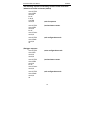
2.1.6. Display Interface
The PC/104 STPC Atlas has an integrated 18Bit TFT (1 pixel/clock) interface (connector X503).
The power supply for the display can be set to 3.3V (default) or +5V via
solder jumper LJP501 :
LJP501
VCC Display
1-2 : +5V
2-3 : +3,3V (default)
1
2
3
Connector X502 provides backlight power +5V or +12V , selected by
solder jumper LJP504 :
LJP504
Backlight Power
1-2 : +5V (default)
2-3 : +12V
123
X502
17
PC104 STPC Atlas User's Manual
Installation
2.2. Watchdog
A watchdog function is implemented in the W83977EF Super I/O.
If the watchdog is enabled a counter is started which creates a reset if it
is not retriggered within a specified time window.
The time window can be set to 1..255 seconds or to 1..255 minutes.
Here is a sample program for setting up the watchdog :
Initialisation :
mov dx,370h
mov al,87h
out dx,al
out dx,al
;enter configuration mode
mov dx,370h
mov al,2ch
out dx,al
inc dx
in al,dx
and al,0cfh
or al,10h
out dx,al
;configure GPIO16
mov dx,370h
mov ax,0707h
out dx,ax
mov ax,0ae6h
out dx,ax
;Device 7
mov ax,0807h
out dx,ax
;Device 8
mov ax,0130h
out dx,ax
;activate device
18
PC104 STPC Atlas User's Manual
Installation
;Use following sequence if watchdog counter counts in seconds
;otherwise it counts in minutes (default)
mov dx,370h
mov al,0f4h
out dx,al
inc dx
in al,dx
or al,40h
out dx,al
;end of sequence
mov dx,370h
mov al,0f2h
out dx,al
inc dx
mov al,Count
out dx,al
;load and start counter
mov dx,370h
mov al,0aah
out dx,al
ret
;exit configuration mode
;Retrigger sequence
mov dx,370h
mov al,87h
out dx,al
out dx,al
;enter configuration mode
mov dx,370h
mov al,0f2h
out dx,al
inc dx
mov al,Count
out dx,al
;load and start counter
mov dx,370h
mov al,0aah
out dx,al
ret
;exit configuration mode
19
PC104 STPC Atlas User's Manual
Installation
2.3. Interrupts, DMA channels, Upper memory
IRQ
0
1
2
3
4
5
6
7
8
9
10
11
12
13
14
15
(1)
(2)
used for
Timer 0
Keyboard
Slave 8259
COM2
COM1
Floppy Disk Controller
LPT1
Real Time Clock
(Ethernet Controller)
PS/2 Mouse
Floating Point Unit
IDE0
-
available
No
No
No
No
No
Yes
No
No
No
(Yes)
Yes
Yes
No
No
No
Yes
comment
(1)
(1)
(2)
(1)
If the device is disabled in SETUP, the interrupt is available.
If the PCI-Ethernet controller is present, typically IRQ9 is allocated by the
BIOS. This can be changed via SETUP.
DMA channels :
DMA
0
1
2
3
4
5..7
used for
----Floppy Disk Controller
--Cascade
---
available
Yes
Yes
No
Yes
No
Yes
comment
Upper Memory Map :
Upper Memory
C0000h..C7FFFh
C8000h..EBFFFh
used for
VGA BIOS
available
No
Yes
EC000h..EFFFFh
F0000h..FFFFFh
(Yes)
System BIOS
No
20
comment
ISA bus or shadow RAM
(DiskOnChip)
Used by System BIOS
during POST
PC104 STPC Atlas User's Manual
Installation
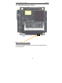
2.4. Connectors
X1001
Floppy
(solder side)
X401b
USB1
X901
Ethernet
RJ45
X401a
USB0
1
1
1
X501, CRT
X503
TFT
Display
(digital)
5
5
1
123
1
1
1
STPC
Atlas
CPU
1
X1203, EIDE
1
X602, COM 2
X601, COM 1
X502
Backlight
Power
1
1
X1002
COM 3
1
X1003
COM 4
1
X1004
LPT
1
X1102
Keyboard,
Mouse,
Reset
1
X801
Power
X1201
PC/104 (ISA bus)
21
PC104 STPC Atlas User's Manual
Installation
2.4.1. Connector types
Connector
Pins
Type
LCD Backlight Power
3
JST B3B-EH-A
Power
4
AMP 171826-4
PC104
104
stack through, 2.54mm
IDE
44
SMT, 2mm, pin header
Floppy
26
FFC,
Weitronic 553-1-26-20-10
LPT1
26
SMT, 2.54mm, pin header
COM1
10
SMT, 2.54mm, pin header
COM2
10
SMT, 2.54mm, pin header
COM3
10
SMT, 2.54mm, pin header
COM4
10
SMT, 2.54mm, pin header
USB0
5
SMT, 2.54mm, pin header
USB1
5
SMT, 2.54mm, pin header
CRT Interface
10
SMT, 2.54mm, pin header
Keyboard/Mouse/Speaker/Reset
10
SMT, 2.54mm, pin header
LAN TBASE100/10
10
SMT, 2.54mm, pin header
TFT Interface
34
SMT, 2 mm, pin header
22
PC104 STPC Atlas User's Manual
Installation
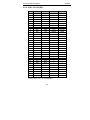
2.4.2. X1201 PC/104 (ISA)
Pin
0
1
2
3
4
5
6
7
8
9
10
11
12
13
14
15
16
17
18
19
20
21
22
23
24
25
26
27
28
29
30
31
32
A
—
/IOCHCK
SD7
SD6
SD5
SD4
SD3
SD2
SD1
SD0
IOCHRDY
AEN
SA19
SA18
SA17
SA16
SA15
SA14
SA13
SA12
SA11
SA10
SA9
SA8
SA7
SA6
SA5
SA4
SA3
SA2
SA1
SA0
GND
B
—
GND
RESET
+5V
IRQ9
(-5V)*
DRQ2
(-12V)*
/0WS
+12V
GND
/SMEMW
/SMEMR
/IOWC
/IORC
/DACK3
DRQ3
/DACK1
DRQ1
/REFSH
SYSCLK
IRQ7
IRQ6
IRQ5
IRQ4
IRQ3
/DACK2
TC
BALE
+5V
OSC
GND
GND
C
GND
SBHE#
LA23
LA22
LA21
LA20
LA19
LA18
LA17
MRDC#
MWTC#
SD8
SD9
SD10
SD11
SD12
SD13
SD14
SD15
KEY
—
—
—
—
—
—
—
—
—
—
—
—
—
(-12V)*, (-5V)* : -12V, -5V not supported
23
D
GND
MEMS16#
IOCS16#
IRQ10
IRQ11
IRQ12B
IRQ15
IRQ14
DACK0#
DRQ0
DACK5#
DRQ5
DACK6#
DRQ6
DACK7#
DRQ7
+5 V
MASTER#
GND
GND
—
—
—
—
—
—
—
—
—
—
—
—
—
PC104 STPC Atlas User's Manual
Installation
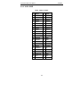
2.4.3. X1203 EIDE
44pin , 2mm pin header
Pin
Name
Pin Name
1
/IDE-RESET
2
GND
3
DATA7
4
DATA
5
DATA6
6
DATA9
7
DATA5
8
DATA10
9
DATA4
10
DATA11
11
DATA3
12
DATA12
13
DATA2
14
DATA13
15
DATA1
16
DATA14
17
DATA0
18
DATA15
19
GND
20
n.c.
21
n.c.
22
GND
23
/IDEIOW
24
GND
25
/IDEIOR
26
GND
27
IORDY
28
BALE
29
n.c.
30
GND
31
INTRQ
32
/IOCS16
33
IDEADR1
34
n.c.
35
IDEADR0
36
IDEADR2
37
/IDECS0
38
/IDECS1
39
/IDEACTIV
40
GND
41
+5 V
42
+5 V
43
GND
44
reserved
24
PC104 STPC Atlas User's Manual
Installation
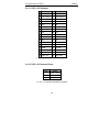
2.4.4. X1001 Floppy
FFC connector
Pin
Name
1
+5V
2
INDEX#
3
+5V
4
DS0
5
+5V
6
DSKCHG
7
n.c.
8
n.c.
9
n.c.
10
MTR0
11
nc
12
DIR#
13
n.c.
14
STEP#
15
GND
16
WDATA#
17
GND
18
WGATE#
19
n.c.
20
TRK0#
21
n.c.
22
WRTPRT#
23
GND
24
RDATA#
25
GND
26
HDSEL#
25
PC104 STPC Atlas User's Manual
Installation
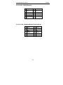
2.4.5. X1004 Parallel Port
Pin
Name
Pin
Name
1
STROBE#
2
AFD#
3
D0
4
ERR#
5
D1
6
INIT#
7
D2
8
SLIN#
9
D3
10
GND
11
D4
12
GND
13
D5
14
GND
15
D6
16
GND
17
D7
18
GND
19
ACK#
20
GND
21
BUSY
22
GND
23
PE
24
GND
25
SLCT
26
n.c.
Pin
Name
2.4.6. X601 COM 1 (RS232)
Pin
Name
1
DCD#
2
DSR#
3
RxD
4
RTS#
5
TxD
6
CTS#
7
DTR#
8
RI#
9
GND
10
n.c.
Pin
Name
2.4.7. X602 COM 2 (RS232)
Pin
Name
1
DCD#
2
DSR#
3
RxD
4
RTS#
5
TxD
6
CTS#
7
DTR#
8
RI#
9
GND
10
n.c.
26
PC104 STPC Atlas User's Manual
Installation
2.4.8. X1001 COM 3 (RS232)
Pin
Name
Pin
Name
1
DCD#
2
DSR#
3
RxD
4
RTS#
5
TxD
6
CTS#
7
DTR#
8
RI#
9
GND
10
n.c.
Pin
Name
2.4.9. X1002 COM 4 (RS232)
Pin
Name
1
DCD#
2
DSR#
3
RxD
4
RTS#
5
TxD
6
CTS#
7
DTR#
8
RI#
9
GND
10
n.c.
2.4.10. X501 CRT
Pin Name
Pin Name
1
RED
2
GND
3
GREEN
4
GND
5
BLUE
6
DDC0
7
HSYNC
8
DDC1
9
VSYNC
10
GND
27
PC104 STPC Atlas User's Manual
Installation
2.4.11. X503 LCD Interface
Pin Name
Pin Name
1
GND
2
GND
3
+5V / 3,3V (*)
4
+5V / 3,3V (*)
5
ENVCC
6
GND
7
R0
8
R1
9
R2
10
R3
11
R4
12
R5
13
G0
14
G1
15
G2
16
G3
17
G4
18
G5
19
B0
20
B1
21
B2
22
B3
23
B4
24
B5
25
GND
26
SHFTCLK
27
GND
28
FPLINE
29
FPFRAME
30
DE
31
ENBLIGHT
32
ENVDD
33
DDC CLK
34
DDC SDA
(*) +5V / +3,3V jumper selectable (LJP501)
2.4.12. X502 LCD Inverter Power
Pin
Name
1
+12V / +5V (*)
2
GND
3
PWM
(*) +5V / +12V jumper selectable (LJP504)
28
PC104 STPC Atlas User's Manual
Installation
2.4.13. X901 RJ45 (Ethernet)
Pin Name
Pin Name
1
TX+
2
TX-
3
RX+
4
Floating GND
5
Floating GND
6
RX-
7
Floating GND
8
Floating GND
9
n.c.
10
n.c.
2.4.14. X1102 Keyboard/Mouse/Speaker/Reset
Pin Name
Pin Name
1
KData
2
MData
3
GND
4
+5V
5
KClock
6
MClock
7
HDLED
8
Reset IN
9
GND
10
Speaker
29
PC104 STPC Atlas User's Manual
Installation
2.4.15. X401a USB0
Pin Name
1
VCC_USB0
2
USB0N
3
USB0P
4
GND
5
Shield_USB0
2.4.16. X401b USB1
Pin Name
1
VCC_USB1
2
USB1N
3
USB1P
4
GND
5
Shield_USB1
2.4.17. X801 Power
Pin
Name
1
+5V
2
GND
3
GND
4
+12V
30
COM4
LPT
COM3
Display
PC/104 STPC Atlas
PC/104
31
USB
3,5 " Floppy
VGA cable 10pin
LAN cable 10pin
FFC - Floppy cable
interface cable 40pin
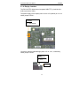
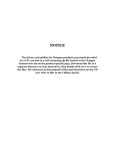
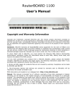
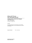
Connection diagram for STPC Atlas adapterboard (option) / MSC Design Center Neufahrn
34pin 1:1 cable
(drive selects not crossed !)
1
1
1
1
HD-LED
Re
set
Spea
ker
Speaker off
VGA
LAN
COM
2
COM
1
Keyboard
Mouse
Mouse
PC104 STPC Atlas User's Manual
Appendix : STPCA Adapterboard
3. Appendix : STPCA Adapterboard
The optional available STPCA Adapterboard is connected via flat ribbon
cables and provides standard connectors for CRT, LAN, COM1/2, Keyboard, Mouse Floppy, and a reset button.
Floppy