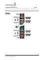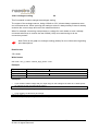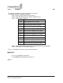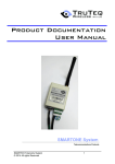
1
Maestro Industrial 10 TruTalk Language Telecommunications Products Maestro Wireless Solutions © 2011 All rights Reserved 1 TABLE OF CONTENTS 1 INTRODUCTION ..................................................................................................................5 1.1 Background ..................................................................................................... 5 2 COMMAND MODE ...............................................................................................................5 2.1 Entering Commands........................................................................................ 6 2.1.1 Serial Port.................................................................................................................6 2.1.2 SMS..........................................................................................................................7 2.1.3 Data call / GPRS mode ............................................................................................7 2.2 Managing the firmware version (on-board software) ....................................... 7 3 COMMANDS & COMMAND LISTS ......................................................................................8 3.1 Commands – the building blocks of Command Lists ...................................... 8 3.2 Command Lists ............................................................................................... 8 3.3 Command Input / output Options .................................................................... 9 3.4 Command text Options.................................................................................... 9 4 COMMAND SUMMARY .....................................................................................................10 5 COMMANDS IN DETIAL ....................................................................................................14 5.1 Query Firmware version 3 ............................................................................. 14 5.2 Query Unit Serial Number 4 .......................................................................... 14 5.3 Query Unit Manufacturing Details 5 .............................................................. 14 5.4 Quick view 6 .................................................................................................. 15 5.5 Signal Analyser configuration 7 ................................................................ 16 5.6 Display Signal Analyser log 8 .................................................................. 16 5.7 Firmware Upgrade 9............................................................................... 17 5.8 Modem Specific Initialisation 10 .................................................................... 17 5.9 Write to phone book Command 11................................................................ 18 5.10 Start-up Command List 15 .......................................................................... 19 5.11 Control timers Command 16 ....................................................................... 20 5.12 Configure timers Command 17 .................................................................. 21 21 5.13 Timer time-out Command List 18 ............................................................... 22 5.14 Output state Command 21 .......................................................................... 23 5.15 Input Debounce Command 32 .................................................................... 24 5.16 Input trigger (low to high) Command List 34 ............................................... 25 5.17 Input trigger (high to low) Command List 35 ............................................... 26 5.18 Send SMS message 41............................................................................... 27 5.19 Send GPRS message 42 ............................................................................ 27 5.20 Custom command list 45 ............................................................................ 28 5.21 Execute Custom command list 46 .............................................................. 28 5.22 Send String command 47 ........................................................................... 29 5.23 Send HEX Array command 48 ................................................................... 29 5.24 ANALOGUE Set-up 50-58........................................................................... 30 5.24.1 Read analogue status 50 ....................................................................................31 5.24.2 Analogue debounce 51 .......................................................................................31 Maestro Wireless Solutions © 2011 All rights Reserved 2 Analogue high trip levels 52 ..........................................................................................32 5.24.3 Analogue low trip levels 53 .................................................................................32 5.24.4 Analogue high trip command list 54 ....................................................................33 5.24.5 Analogue high recover command list 55 .............................................................33 5.24.6 Analogue low recover command list 56 ..............................................................34 5.24.7 Analogue low trip command list 57 .....................................................................34 5.24.8 Analogue scaling 58 ..........................................................................................35 5.25 SIM slot management 60 ........................................................................... 36 5.26 SIM PIN management 63 ........................................................................... 36 5.27 Submit AT command 64 ............................................................................. 37 5.28 GSM reset interval 66................................................................................. 37 5.29 GSM data call reset interval 67 .................................................................. 38 5.30 GSM house keeping interval 68 ................................................................. 38 5.31 RTC: Time-of-Day 73 ................................................................................ 39 5.32 RTC: Date 74 ............................................................................................ 40 5.33 RTC: En/Disable Time-of-Day event 75 .................................................... 40 5.34 RTC: Time-of-Day event time setting 76 .................................................... 41 5.35 RTC: Time-of-Day event command list 77 ................................................. 41 5.36 COUNTERS 80-85 ..................................................................................... 42 5.36.1 Counter Value Load 80 .......................................................................................42 5.36.2 Counter Increment 81..........................................................................................42 5.36.3 Counter Decrement 82 ........................................................................................43 5.36.4 Counter low / high compare values 83 .................................................................43 5.36.5 Counter low compare command list 84 ................................................................43 5.36.6 Counter high compare command list 85 ..............................................................44 5.37 Incoming Voice calls command list 90 ........................................................ 45 5.38 Incoming Data calls command list 91 .......................................................... 45 5.39 Incoming call control 92............................................................................... 46 5.40 Control allowed users Command 95 ........................................................... 46 5.41 LOGGING: Records manager 97 ............................................................... 47 5.42 LOGGING: Write/read 98 ........................................................................... 48 5.43 GPRS Set-up 150-161 ................................................................................ 49 5.43.1 GPRS activate / deactivate 150 ...........................................................................49 5.43.2 GPRS IP address 1 153 .......................................................................................49 5.43.3 GPRS IP address 2 154 .......................................................................................50 5.43.4 GPRS IP address 3 155 .......................................................................................50 5.43.5 TCP Server Port number 156...............................................................................50 5.43.6 TCP Client Port number 157 ................................................................................51 5.43.7 Access Point Name Server 158 ...........................................................................51 5.43.8 User name 159.....................................................................................................51 5.43.9 Password 160.......................................................................................................52 5.43.10 GPRS manager configuration 161 .....................................................................52 5.44 Ping 164-165 ...................................................................................... 53 5.44.1 Ping IP address 164 ............................................................................................53 5.44.2 Keep-alive ping setup 165...................................................................................53 5.45 Serial input event 170-171 ......................................................................... 54 5.45.1 Set Serial input event active / inactive 170 .........................................................54 5.45.2 Command List for the Serial Input Event 171 .....................................................54 5.47 System Hardware Set-up Parameters 251-261 ......................................... 55 5.47.1 Get system uptime 251 .................................................................................55 5.47.2 Set-up Hardware number of inputs and outputs and Analogues 252 ..................55 Maestro Wireless Solutions © 2011 All rights Reserved 3 5.47.3 Set serial input to RS485 254 ........................................................................55 5.47.4 Force a hardware reset 256 ..........................................................................55 5.47.5 Set-up serial port communications parameters 257..........................................56 5.47.6 Set command mode time out 258 ...................................................................57 5.47.7 Set debug on or off 260.................................................................................57 5.47.8 Enable return sms on commands received via sms 261...................................57 5.47.9 Enable auto remote command mode 262 .......................................................57 5.47.10 Set communications Port 263 .....................................................................57 5.47.11 MODBUS 264............................................................................................58 5.47.13 Dial-up mode 266 .......................................................................................59 5.47.14 Data Flushing Delay 267 .............................................................................59 6 APPENDIX A ......................................................................................................................60 7 DISCLAIMER ......................................................................................................................60 8 GLOSSARY ........................................................................................................................60 9 REVISION INFORMATION ................................................................................................60 10 WARNINGS ......................................................................................................................61 11 CONTACTING MAESTROWIRELESS.............................................................................61 12 NOTICES & TRADEMARKS ............................................................................................61 Maestro Wireless Solutions © 2011 All rights Reserved 4 1 INTRODUCTION 1.1 Background The Maestro Industrial 10 telemetry terminal is controlled by a set of commands and parameters called TruTalk Note: The commands in this document are related to firmware V3_55. If your current firmware does not support a specific command that you want to use, then please contact Maestro Wireless Solutions for an upgrade option. The latest version of this document is available for downloading after login from the following link: http://www.maestro-wireless.com 2 COMMAND MODE By default the Maestro Industrial 10 main serial port acts as a standard modem. However this serial port is also used to enter commands and to configure the unit. The AT command AT$TT is used to enter the TruTalk text mode command prompt. In this mode the unit will echo all incoming text, and add command prompts and readable carriage returns as well as line feeds. The command mode will time-out after a default 30 seconds, or can be quitted by typing <ctrl-z>, this will return the Maestro Industrial 10 into normal modem mode. A simplified command mode is also available for use with serial applications by entering AT$RT (RawText). In this mode there will be no echoing or prompts to simplify the serial encapsulation in a typical application. Maestro Wireless Solutions © 2011 All rights Reserved 5 2.1 Entering Commands Commands can be entered via the serial port, sms, GPRS or even data call. 2.1.1 Serial Port Commands can be entered via the serial port, once the unit has started up and printed “Start-up complete!!” on the serial port. COMMAND MODE is entered by typing-in AT$TT<enter> Default serial parameters are: 9600,8,N,1. Maestro Wireless Solutions © 2011 All rights Reserved 6 2.1.2 SMS Commands can be send via sms. Simply sms the command to the unit. Multiple commands can be send in 1 sms. 2.1.3 Note: make sure you are an allowed user before sending an sms to the unit see commands 11 and 95 Data call / GPRS mode Connect to the unit either via data call or TCP connection via GPRS. Once the connection is made then command mode can be entered by sending 3 sequential minuses (---). The remote unit will now be in command mode and ready to receive commands over the air. 2.2 Managing the firmware version (on-board software) The Maestro Industrial 10 includes an application called FLASH MANAGER (FM). This application resides in the protected boot loader space of the microprocessor. At start-up it verifies the FLASH memory content and from there starts the application. The firmware version is printed out on the second line after start-up. It can also be checked with command ?3 on the TruTalk command line. New firmware is loaded onto the unit using Flash Manager. The Flash Manager can be set into boot load mode by either sending it <space> characters at start-up (thus holding in the <space bar> while switching the unit on), or by using command !9 on the TruTalk command line. Maestro Wireless Solutions © 2011 All rights Reserved 7 3 COMMANDS & COMMAND LISTS 3.1 Commands – the building blocks of Command Lists A Command starts with a Control Character (an exclamation mark <!> for a command, or a question mark <?> for a request), followed by a Command Number. This number indicates the action to be performed and are followed by different Parameters, which are always separated by at least one space. Responses by the Maestro Industrial 10 unit are always returned to the Originator (person/machine who sent the request/command) in the same sequence as the request/command was made. Any number of spaces can be used between separate Commands – the extra spaces are interpreted as white space and may be used to enhance readability. Just keep in mind that these spaces are also included in the maximum of 100 characters allowed in a Command List. Double quotes <“ ”> indicates a text field and any control characters (!/?) or numbers contained between these double quotes, are handled as text only. Example: (send SMS – <!41>) Control Character Command Number Space ! 41 Parameter 1 Space Parameter 2 (Text field) 2 “Unit XYZ switched on” Note: Multiple commands can be entered at a time, in both the command mode and in an sms. 3.2 Command Lists A Command List consists of a Control Character (an exclamation mark <!> for a command, or a question mark <?> for a request) and a Command List Number. This is followed by several Commands (minimum = 1, maximum = limitless). The total length of each Command List may not exceed 100 characters. The Command List Number is the association between an event and the following Commands. Example: (start-up event – <!15>) Control Character Command List Number !15 !21 3 1 Command 1 Command 2 !41 2 “Unit XYZ switched on” Note: Only one command list can be entered at a time, in both the command mode and in an sms. Maestro Wireless Solutions © 2011 All rights Reserved 8 3.3 Command Input / output Options The state of a specific digital input or digital output can be specified (in Commands and Command Lists) with the following: 1. <0> - Switch off / disable / deactivate 2. <1> - Switch on / enable / activate 3.4 Command text Options Text is entered between quotation marks “<text>”, the content will be handled as one parameter. One can however add variables into the text area with the use of escape codes. Escape codes are placed between triangular brackets <escape code>. The following escape codes are available: <C1-4> <S1> <T1-5> <O1-20> <I0-20> <A1-8> <AO> <RS> <DQ> <RT> <RD> <CR> <LF> <xHH> <SN> <ST> <IP> <P1-8> Print counter 1 to 4 Print serial input buffer 1 Print timer 1 to 5 remaining time Print digital output 1 to 20 status (1=on 0=off) Print digital input 0 to 20 status (1=on 0=off) (0 = Mains Available on supported units) Print analogue input 1 to 8 Print analogue output Received signal strength indication (0-100, or “—“ if unknown) Insert double quote (“) Insert time from RTC Insert date from RTC Insert Carriage Return Insert Line Feed Insert Byte – format is 0x HEX Insert Serial Number Insert Status string Print own IP address Insert Pulse Counter 1 to 8's value Multiple escape codes can be within 2 brackets: “<A1><A2><A3>” can also be written as “<A1A2A3>” Example of sending a sms with the values of counter 1 and timer 2. !41 1 “The value of counter1=<C1> and the value of timer2=<T2>” If counter 1 was 25 and timer 2 was 14min and 23sec then this sms will display the following: The value of counter1=25 and the value of timer2=00:14:23 Maestro Wireless Solutions © 2011 All rights Reserved 9 4 COMMAND SUMMARY No 3 Request String ?3 Description Software Version 4 ?4 Serial number 5 ?5 Manufacturing details 6 ?6 Quick view (will return all inputs, outputs and signal strength) ?7 Signal logging interval ?8 Query signal log values 7 Command String !7 <interval> 8 9 !9 SERIAL Set modem to receive new firmware 10 !10 ?10 Modem Initialization String 11 !11 <N> <NoString>,<NameString> ?11 <N> Write to phone book 15 !15 <String> ?15 Start-up Commands 16 !16 <N> <Option> ?16 <N> Control timer 17 !17 <N> <Option> ?17 <N> Configure timer 18 !18 <N> <String> ?18 <N> Timer time-out Command lists 21 !21 <N> <Option> ?21 Output state Note: NameString optional N+100 = internal GPIOs 32 !32 <N> <Option> ?32 <N> Input Debounce 34 !34 <N> <String> ?34 Input trigger Commands (low to high) 35 !35 <N> <String> ?35 Input trigger Commands (high to low) 41 !41 <N> <String> SMS Message sending 42 !42 <N> <time> “Event String” Send event over GPRS fallback by sending SMS to phonebook position N 45 !45 <N> <String> 46 !46 <N> Execute custom command list number <N> 47 !47 <Dest> “String” Send String to <Dest> ?45 Define customised list of Commands 2 = Serial Port (1A – master ext) 3 = Serial Port (1B – slave int) 4 = I2C @ add 10010010 48 !48 <Dest> <Hex-Array> 50 Send array of HEX chars to <Dest> ?50 Display Analog input values 51 !51 <N> <Option> ?51 <N> Analog Input Debounce 52 !52 <N> <highRecover> <highTrip> ?52 <N> Analogue input configuration (High Trip Points) Maestro Wireless Solutions © 2011 All rights Reserved 10 53 !53 <N> <lowTrip> <lowRecover> ?53 <N> Analogue input configuration (Low Trip Points) 54 !54 <N> <String> ?54 <N> Analogue input High Trip Command list 55 !55 <N> <String> ?55 <N> Analogue input High Recover Command list 56 !56 <N> <String> ?56 <N> Analogue input Low Recover Command list 57 !57 <N> <String> ?57 <N> Analogue input Low Trip Command list 58 !58 <N> <lowLimit> <highLimit> <unit> ?58 <N> Setup analog input scaling and units 60 !60 <Option> ?60 <N> Set prefered SIM card slot 63 !63 <String> Set PIN code 64 !64 <String> <optional var> Submit AT commands 66 !66 <Option> ?66 GSM Reset setup 67 !67 <Option> ?67 Allowed Data Call time 68 !68 <String> ?68 HouseKeeping interval 73 !73 <Option> ?73 Day-Time setting on clock 74 !74 <Option> ?74 Date setting on clock 75 !75 <1or2> <Option> ?75 <1or2> en/disable Day-Time event 76 !76 <1or2> <Option> ?76 <1or2> Day-Time event time-setting 77 !77 <1or2> <String> ?77 <1or2> Day-Time event script 80 !80 <N> <Option> ?81 <N> Counter Value Load 81 !81 <N> <Option> Increment counter value 82 !82 <N> <Option> Decrement counter value 83 !83 <N> <ValueLow> <ValueHigh> ?83 <N> Counter Compare Values 84 !84 <N> <String> ?84 <N> Counter <= Compare Low Command lists 85 !85 <N> <String> ?85 <N> Counter >= Compare High Command lists 90 !90 <PB pos> <String> ?90 <PB pos> Incoming calls (Voice) Commands 91 !91 <PB pos> <String> ?91 <PB pos> Incoming calls (Data) Commands 92 !92 <0/1> 95 !95 <N><Option> ?95 <N> Control allowed users 97 !97 ALL ?97 Query number of logs or erase all logs 98 !98 <String> ?98 <N> Write log record, or read <N> number of logs 150 !150 (1/0) ?150 GPRS Active/Inactive 151 !151 (1/0) ?151 GPRS Attached/Detached 152 !152 (1/0) ?152 GPRS Client/Server Maestro Wireless Solutions © 2011 All rights Reserved Answer(1) or reject(0) incoming call 11 153 !153 IP address ?153 IP address 1 (server mask) 154 !154 IP address ?154 IP address 2 (client connect) ?155 IP address 3 (own IP) 155 156 !156 <V> ?156 Server Listen Port no 157 !157 <V> ?157 Client Connection Port no 158 !158 APN add ?158 Access Point Name Server 159 !159 UserName ?159 APN username 160 !160 PassWord ?160 APN password 161 !161 <A> <B> <C> ?161 GPRS manager setup 164 !164 “IP address” 165 !165 <N> “optional-IP add” ?165 keep-alive ping 170 !170 (0 or time-out) ?170 Serial input Manager Active/Inactive 171 !171 <String> ?171 Execute <String> when serial input event occurs ?251 Get System uptime 251 ping “IP address” 252 !252 <digIn> <digOut> <AnIn> ?252 IO setup 254 !254 (1/0) ?254 RS485 enable / disable 256 !256 257 !257 <BaudRate> <IO_Framing> ?257 Set communications parameters 258 !258 <seconds> ?258 Set command mode timeout 260 !260 (0->4) ?260 Debugging to Serial port Reset Unit 0- No Debug 1- GSM Debug 2- System Debug 3- Allowed users Debug 4- Command handler Debug 261 !261 (0/1) ?261 Return SMS on Commands 0 – no return sms 1 – return sms (default) 262 !262 (0/1) ?262 Auto Remote Command Mode 0 – disable (default) 1 – enable 263 !263 (0/1/2) ?263 Communications Port 1 – No link to GSM 2 – Only link data 3 – Always linked 264 !264 (0/1) Maestro Wireless Solutions © 2011 All rights Reserved ?264 Modbus enable / disable 12 265 !265 (0/1) ?265 Mains input enable / disable 266 !266 (0/1) ?266 Dial-up option 267 !266 <N> ?266 Data flush delay Maestro Wireless Solutions © 2011 All rights Reserved 13 5 COMMANDS IN DETIAL 5.1 Query Firmware version________________________ 3 This request is used to get the current firmware version installed on the device. Write format: ?3 Example: Operator to Unit Unit to Operator ?3 Request firmware version $3: Firmware Version : Vx.xxx 5.2 Query Unit Serial Number ______________________ 4 This request is used to get the device’s serial number. Write format: ?4 Example: Operator to Unit Unit to Operator ?4 $4: Serial# : TFxxxxxx Request serial number 5.3 Query Unit Manufacturing Details________________ 5 This request is used to get the device’s manufacturing details. Write format: ?5 Example: Operator to Unit Unit to Operator ?5 Request manufacturing details $5: Manuf. details : xxxxxxxx Maestro Wireless Solutions © 2011 All rights Reserved 14 5.4 Quick view ___________________________________ 6 This request is used to obtain the status of ALL the outputs and inputs, as well as the GSM signal strength (as a percentage). The status will be supplied in the following format: Example: IPT: ABCD OPT: MN ANI: a, b SIG: XX% (Digital input status) (Digital output status) (Analogue input status) (Signal strength) Where: A is the status of Input 1 B is the status of Input 2 C is the status of Input 3 D is the status of Input 4 (1 = on, 0 = off) (1 = on, 0 = off) (1 = on, 0 = off) (1 = on, 0 = off) M is the status of Output 1 N is the status of Output 2 (1 = on, 0 = off) (1 = on, 0 = off) a is the status of Analogue Input 1 b is the status of Analogue Input 2 Write format: ?6 Example: Operator to Unit Unit to Operator Maestro Wireless Solutions © 2011 All rights Reserved ?6 OPT: 0001 IPT: 1001 SIG: 85% Request status Return status (if only one Maestro Industrial 10 digital input/output card is fitted) 15 5.5 Signal Analyser configuration 7 This command is used to set the recording interval for the received signal analyser tool. Setting it to 0 switches this functionality off. Write format: !7 <interval> ?7 Example: Operator to Unit Unit to Operator Operator to Unit Unit to Operator !7 30 Set the unit to log the received signal every 30minutes. $7: signal log interval 30 minutes ?7 Request current log interval $7: signal log interval 30 minutes 5.6 Display Signal Analyser log 8 This command is used to display the data logged by the signal analyser. A 'c' character before a value means that there was a big change in the received signal quality, that did not fall on the record interval. The received values are between 0 (no signal) and 31 (full signal). The unit must have a SIM card that is registered on the network for the logger to log. Write format: ?8 Example: Operator to Unit Unit to Operator ?8 Query the signal log $8: 26 28 25 29 c22 25 29 30 28 30 30 30 c20 c30 28 29 30 29 26 30 28 Maestro Wireless Solutions © 2011 All rights Reserved 16 5.7 Firmware Upgrade 9 This Command is used to upload new firmware onto the product using the on-board Flash Manager. This command sets the 'new firmware upload flag' in the Flash Manager and then restarts the unit. Use MaestroYATPro's firmware function to upload the new firmware. Write format: !9 SERIAL !9 OTA IP_address:Port# <APN_name> [username] [password] 5.8 Modem Specific Initialisation 10 This Command is used to store a list of AT commands to be performed when the device is powered-up. The user can use this to enable/disable modem specific type of commands eg: set hardware flow control to none with AT+IFC=0,0 and set auto answer on with ATS0=1. Write format: !10 <STRING> (AT commands must be space delimited) ?10 Example: Operator to Unit Unit to Operator Operator to Unit Unit to Operator !10 AT+IFC=0,0 ATS0=1 Set modem H/W flow control to none and auto answer incoming calls after 1 ring. $10: User Modem Init. String: AT+IFC=0,0 ATS0=1 ?10 Request current user specific init string $10: User Modem Init. String: AT+IFC=0,0 ATS0=1 Note: The unit will re-start to implement the change Tip: init string to set modem for AMR: !10 AT+CBST=0,0,1 AT+CICB=0 AT+CSNS=4 ATS0=1 Maestro Wireless Solutions © 2011 All rights Reserved 17 5.9 Write to phone book Command _________________ 11 This Command is used to store user’s cell phone numbers in the SIM Phone Book. The maximum number of cell phone numbers that can be stored, will be determined by the SIM card in use (typically 200). These numbers can be overwritten with new numbers (if required). It is important to have the users names and numbers in the phone book, as it used for sending and receiving sms. Please also see the allowed user command number 95. Note: These numbers are stored on the SIM card and not on the unit, so these numbers will have to be re-entered if the SIM card is swapped out or replaced. Write format option1: Only the user’s number is stored in this format. !11 <Phone book position> <Cell phone number> < Phone book position> <Cell phone number>….. ?11 <Phone book position> <Phone book position> <Phone book position>….. Example: Operator to Unit Unit to Operator Operator to Unit Unit to Operator !11 15 +27835638592 117 +27836479220 Write phone number 0835638592 in position 15 and phone number 0836479220 in position 117 in the SIM phone book $11 15->+27835638592 117->+27836479220 ?11 15 117 Request current phone numbers in positions 15 and 177 in the SIM phone book $11 15->+27835638592 117->+27836479220 Write format option2 (recommended): The user’s number and name is stored in this format. !11 <Phone book position> <Cell phone number>,<person’s name> < Phone book position> <Cell phone number>,<person’s name>….. ?11 <Phone book position> <Phone book position> <Phone book position>….. Example: Operator to Unit Unit to Operator Operator to Unit Unit to Operator !11 15 Write phone number 0835638592 in position +27835638592,Peter 15 and phone number 0836479220 in position 117 +27836479220,Jhon 117 in the SIM phone book $11 15->+27835638592,Peter 117->+27836479220,John ?11 15 117 Request current phone numbers in positions 15 and 177 in the SIM phone book $11 15->+27835638592,Peter 117->+27836479220,John Maestro Wireless Solutions © 2011 All rights Reserved 18 5.10 Start-up Command List ________________________ 15 The device can be programmed to perform certain Commands when a start-up (power-up) condition occurs, for example switching certain outputs on or off, sending an SMS message to a specific number in the SIM phone book, etc. Write format: !15 <Command1> <Command2> <Command3> ?15 Example: Operator to Unit Unit to Operator Operator to Unit Unit to Operator !15 !21 3 1 !21 4 0 !41 2 “Unit XYZ switched on” Start-up Command List Number, Switch output 3 on, Switch output 4 off, Send an SMS message to phone book position 2 that reads: "Unit XYZ switched on” $15 !21 3 1 !21 4 0 !41 2 “Unit XYZ switched on” ?15 Request current Start-up Command List configuration $15 !21 3 1 !21 4 0 !41 2 “Unit XYZ switched on” Note: The unit will re-start to implement the change Maestro Wireless Solutions © 2011 All rights Reserved 19 5.11 Control timers Command_______________________ 16 There are 5 separate timers in the Maestro Industrial 10 and this Command can be used to start or stop any of the timers. When a specific timer runs out, a Command associated with the event could be to start the timer again, thereby creating a recurring timed event. Tip: Remember to first load a time into the timer with command 17 before starting the count down timer. Option Parameters: 0 = stop timer 1 = start count-down timer 2 = start count-up timer Write format: !16 <Timer number> <Option> <Timer number> <Option> <Timer number> <Option>….. ?16 <Timer number> <Timer number> <Timer number>….. Example: Operator to Unit Unit to Operator Operator to Unit Unit to Operator !16 4 0 1 1 $16: 1->1 4->0 ?16 1 4 $16: 1->1 4->0 Stop timer 4 and start timer 1 Request current status of timers 1 and 4 Note: That when the count-up option is used there will be no event script associated with the timer. The event script is only executed when the timer reaches zero. Maestro Wireless Solutions © 2011 All rights Reserved 20 5.12 Configure timers Command ____________________ 17 This Command can configure the 5 timers’ characteristics in hours, minutes and seconds to a maximum of 99 hours, 59 minutes and 59 seconds. If not configured, the default will be ‘0’ (no timer). Write format: !17 <Timer number> <hh:mm:ss> <Timer number> <hh:mm:ss>….. ?17 <Timer number> <Timer number> <Timer number>….. Example: Operator to Unit Unit to Operator Operator to Unit Unit to Operator !17 1 00:10:30 5 Set timer 1 to 10 minutes and 30 seconds, set 06:00:00 timer 5 to 6 hours $17: 1->00:10:30 5->06:00:00 ?17 5 1 Request current configuration of timers 5 and 1 $17: 5->05:59:51 1->00:10:21 Note: This Command doesn’t physically switch any of the timers on, but just configures their characteristics. Use the Control timers Command <!16> to switch any/all of the timers on. Maestro Wireless Solutions © 2011 All rights Reserved 21 5.13 Timer time-out Command List __________________ 18 The timers can be programmed to perform certain Commands when it runs out, for example it could switch certain outputs on or off, send an SMS message to a specific number in the SIM phone book, etc. Write format: !18 <Timer number> <Command1> <Command2> <Command3> ?18 <Timer number> Example: Operator to Unit Unit to Operator Operator to Unit Unit to Operator !18 4 !21 3 1 !21 4 0 !41 7 “Timer timed out” !17 4 24:00:00 Timer time-out Command List Number – in the event of a time-out of timer number 4 the following Commands will be performed: Switch output 3 on, Switch output 4 off, Send an SMS message to phone book position 7 that reads: "Timer timed out”, Re-start the timer again (recurring timed event) $18 1->!21 3 1 !21 4 0 !41 7 “Timer timed out” !17 4 24:00:00 ?18 4 Request current Timer timed-out Command List configuration for Timer number 4 $18 1->!21 3 1 !21 4 0 !41 7 “Timer timed out” !17 4 24:00:00 Maestro Wireless Solutions © 2011 All rights Reserved 22 5.14 Output state Command ________________________ 21 This Command is used to switch the defined output on or off, or to toggle (if it is on then switch it off and if it is off then switch it on) the output. Option Parameters: 0 = switch output off 1 = switch output on 2 = toggle output 3 = pulse the output Write format: !21 <Output number > <Option> <Output number > <Option>….. Example: Operator to Unit !21 2 1 4 0 1 2 Unit to Operator OTP: 1100 Switch output 2 on, switch output 4 off, toggle output 1 Note: The status of the standard outputs are volatile, thus the outputs will always start in the off position when the unit is power-cycled. Use start-up command list to set an output to a desired state at start-up. Maestro Wireless Solutions © 2011 All rights Reserved 23 5.15 Input Debounce Command _____________________ 32 The Debounce period is the amount of time that lapses before a specific task is performed. This Command can configure the Debounce period of an input in hours, minutes and seconds to a maximum of 99 hours, 59 minutes and 59 seconds. If not configured, the input will (by default) have no Debounce period. Note: Digital input # 0 refers to units with an internal battery that has a mains available option. Write format: !32 <Input number> < hh:mm:ss > <Input number> < hh:mm:ss >….. ?32 <Input number> <Input number> <Input number>….. Example: Operator to Unit !32 1 00:00:25 Unit to Operator Operator to Unit No response ?32 1 Unit to Operator $32 00:00:25 Maestro Wireless Solutions © 2011 All rights Reserved Configure input 1 to have a 25 second debounce period before executing the associated Command List Request current Debounce period configuration of input 1 24 5.16 Input trigger (low to high) Command List _________ 34 The device can be programmed to perform certain Commands when an input is triggered/opened/switched on, for example switch certain outputs on or off, start the timer, send an SMS message to a specific number in the SIM phone book, etc. Note: Digital input # 0 refers to units with an internal battery that has a mains available option. Write format: !34 <Input number> <Command1> <Command2> <Command3> <;> ?34 <Input number> <Input number>….. Example: Operator to Unit !34 1 !21 3 1 !21 4 0 !41 2 “Door has been opened”; Unit to Operator Operator to Unit No response ?34 1 Unit to Operator Command List Number – in the event of a trigger on input 1 then the following Commands will be performed: Switch output 3 on, Switch output 4 off Send an SMS message to phone book position 2 that reads: "Door has been opened” Request current Input trigger (low to high) Command List configuration for input 1 1: !34 1 !21 3 1 !21 4 0 !41 2 “Door has been opened”; Maestro Wireless Solutions © 2011 All rights Reserved 25 5.17 Input trigger (high to low) Command List _________ 35 In some applications one would want the device to perform certain Commands in the event when an input is switched off/closed/return to its original status or position. Note: Digital input # 0 refers to units with an internal battery that has a mains available option. Write format: !35 <Input number> <Command1> <Command2> <Command3> <;> ?35 <Input number> <Input number>….. Example: Operator to Unit !35 1 !21 3 0 !21 4 1 !41 2 “Door has been closed”; Unit to Operator Operator to Unit No response ?35 1 Unit to Operator Command List Number – in the ‘off’ event of input 1 then the following Commands will be performed: Switch output 3 off, Switch output 4 on, Send an SMS message to phone book position 2 that reads: "Door has been closed” Request current Input trigger (high to low) Command List configuration for input 1 1: !35 1 !21 3 0 !21 4 1 !41 2 “Door has been closed”; Maestro Wireless Solutions © 2011 All rights Reserved 26 5.18 Send SMS message ___________________________ 41 This Command is used to send SMS messages to any of the cell phone numbers in positions 1 to 200 of the SIM Phone Book. The same SMS message can be sent to multiple phone numbers in a single Command. Write format: !41 <Position number> <Position number> <Position number> <”> <Text message> <”> Example: Operator to Unit !41 3 55 69 “Hello World” 1 “Hello World was sent” Unit to Operator $41: message send status. Send “Hello World” to the cellphone numbers in positions 3, 55 and 69 and send “Hello World was sent” to the cellphone number in position 1 in the SIM Phone Book 5.19 Send GPRS message __________________________ 42 This command creates a TCP Client connection to IP address 2 on port # 2 (see command 154 and 157). A SIM phone book position must also be supplied in case the GPRS connection was unsuccessful. The message will then be send via SMS. The connection open time-out must also be supplied (this field is in seconds). Note: If the connection was made from command mode, and a time-out field was specified then the unit will quit command mode, however if the time-out field was set to zero, then the unit will stay in command mode after the message was send. Write format: !42 <Position number> <Connection Open Time-out> <”> <Text message> <”> Example: Operator to Unit !42 3 1 “Input 1 sw on!” Unit to Operator $42: message send status. Maestro Wireless Solutions © 2011 All rights Reserved Send “Input 1 sw on!” to the IP address 2 on port # 2.If unsuccessful then send “Input 1 sw on!” via sms to phone book position 3. 27 5.20 Custom command list _________________________ 45 This Command is used to create custom command lists. There are 10 custom command lists. Tip: Use custom command lists when deferent events must execute the same script, or when the 100 characters associated with an event is to little. Write format: !45 <List number> <Command List> Example: Operator to Unit Unit to Operator !45 5 !41 1 2 “Door status = <I4>” When custom command list 5 is called then it will send a sms to phone book positions 1 & 2 giving the status of the door switch $45: 5->!41 1 2 “Door status = <I4>” 5.21 Execute Custom command list _________________ 46 This Command is used to generate the event that will execute the associated custom command list. Write format: !46 <List number> Example: Operator to Unit Unit to Operator !46 5 Execute custom command list 5. $46: Now running cmd list: 5 Tip: Use command 261 to switch off return sms if the custom command list is going to send the required sms. Maestro Wireless Solutions © 2011 All rights Reserved 28 5.22 Send String command _________________________ 47 This Command is used to send a string to either the serial port (Dest=2) or the TWI LCD (Dest = 4). Write format: !47 <Destination> “String” Example: Operator to Unit Unit to Operator !47 4 “Input4=<I4>” Write input 4 status to LCD $47: text message send OK Note: See appendix A for the various LCD options that can be included in the string send to the LCD, ex ‘goto’ & ‘cls’. 5.23 Send HEX Array command _____________________ 48 This Command is used to send an array of HEX formatted characters including <NULL> to either the serial port (Dest=2) or the TWI LCD (Dest = 4). Write format: !48 <Destination> <HEX-ARRAY> Example: Operator to Unit !48 2 00010305060AFF Unit to Operator $48: array send OK Maestro Wireless Solutions © 2011 All rights Reserved Write <x00 x01 x03 x05 x06 x0A xFF> to serial port 29 5.24 ANALOGUE Set-up ____________________________ 50-58 Separate Command Lists are linked to the events where an analogue value passes a certain level. The following diagram explains which command lists are associated with which level. Figure An1: Maestro Wireless Solutions © 2011 All rights Reserved 30 5.24.1 Read analogue status 50 This Command is used to read the analogue values. The default value format will be an integer between 0 and 1023. Note: If an analogue was scaled using command 58, then the scaled value will be displayed. Read format: ?50 Example: Operator to Unit Unit to Operator ?50 Read analogues $50: 0, 22.3degC, 0, 15.8Vdc 5.24.2 Analogue debounce 51 This Command is used to set/get the analogue delay times. Read format: ?51 <An#> Write format: !51 <An#> <debounceTime> Example: Operator to Unit Unit to Operator Operator to Unit Unit to Operator !51 1 00:00:01 2 24:00:00 Set analogue 1 debounce to 1 second and analogue 2 debounce to 24hours $51: 1->00:00:01 2->24:00:00 ?51 1 2 Query # 1 and 2’s debounce periods $51: 1->00:00:01 2->24:00:00 Maestro Wireless Solutions © 2011 All rights Reserved 31 Analogue high trip levels 52 This Command is used to set/get the analogue high trip and recover levels. Tip: See figure An1 for a better understanding to the use of this command. Read format: ?52 <An#> Write format: !52 <An#> <High level recover value> <High level trip value> Example: Operator to Unit Unit to Operator Operator to Unit Unit to Operator !52 1 854 902 $52: 1->852,902 ?52 1 $52: 1->852,902 5.24.3 Analogue low trip levels 53 This Command is used to set/get the analogue low trip and recover levels. Tip: See figure An1 for a better understanding to the use of this command. Read format: ?53 <An#> Write format: !53 <An#> <Low level trip value> <Low level recover value> Example: Operator to Unit Unit to Operator Operator to Unit Unit to Operator !53 1 301 357 $53: 1->301,357 ?53 1 $53: 1->301,357 Maestro Wireless Solutions © 2011 All rights Reserved 32 5.24.4 Analogue high trip command list 54 This Command is used to set/get the analogue high trip command list. Tip: See figure An1 for a better understanding to the use of this command. Read format: ?54 <An#> Write format: !54 <An#> <CMD list> Example: Operator to Unit Unit to Operator Operator to Unit Unit to Operator !54 1 !21 2 1 $54: !21 2 1 ?54 1 $54: !21 2 1 5.24.5 Analogue high recover command list 55 This Command is used to set/get the analogue high recover command list. Tip: See figure An1 for a better understanding to the use of this command. Read format: ?55 <An#> Write format: !55 <An#> <CMD list> Example: Operator to Unit Unit to Operator Operator to Unit Unit to Operator !55 1 !21 2 0 $55: !21 2 0 ?55 1 $55: !21 2 0 Maestro Wireless Solutions © 2011 All rights Reserved 33 5.24.6 Analogue low recover command list 56 This Command is used to set/get the analogue low recover command list. Tip: See figure An1 for a better understanding to the use of this command. Read format: ?56 <An#> Write format: !56 <An#> <CMD list> Example: Operator to Unit Unit to Operator Operator to Unit Unit to Operator !56 1 !21 1 0 $56: !21 1 0 ?56 1 $56: !21 1 0 5.24.7 Analogue low trip command list 57 This Command is used to set/get the analogue low trip command list. Tip: See figure An1 for a better understanding to the use of this command. Read format: ?57 <An#> Write format: !57 <An#> <CMD list> Example: Operator to Unit Unit to Operator Operator to Unit Unit to Operator !57 1 !21 1 1 $57: !21 1 1 ?57 1 $57: !21 1 1 Maestro Wireless Solutions © 2011 All rights Reserved 34 5.24.8 Analogue scaling 58 This Command is used to set/get the analogue scaling. The output of the analogue sensor, being 4-20mA or 0-5V, almost always represents some sort of measurement. When queering the analogue value it’s always handy to have it already scaled to the correct range and unit of the measured device. When for example: measuring a temperature or voltage it’s much better to have it already converted rather than to receive the raw 0-2048 (11bit) count and having to do the conversion yourself. Note: Refer to the graph on analogue scaling (below) for more information regarding point descriptions Read format: ?58 <An#> Write format: !58 <An#> <An_0_Value> <Sensor_High_Point> <unit> Example: Operator to Unit Unit to Operator Operator to Unit Unit to Operator !58 1 0 300 Vac $58: 1->0.00,300.00,Vac ?58 1 $58: 1->0.00,300.00,Vac Examples: If you measure mains voltage and your input range on the analogue converter is 0->300V input 05V output then use command 58 as follows: !58 1 0 300 Vac When you query analogue 1 it will return eg: 235.6Vac • • If you measure a value as a percentage !58 1 0 100 % When you query analogue 1 it will return eg: 65.35% Maestro Wireless Solutions © 2011 All rights Reserved 35 4-20mA sensor graph • If you have a Maestro 4-20mA temperature sensor attached to the 0-20mA analogue input, then you need to set-up the scaling as follows: !58 1 -81.25 +125 degC Formula to calculate the AN_0_Value in a 4-20mA system is: AN_0_Value = Sensor_Low_Point + ((sensor range)/16)*(-4)) Note: Any value returned lower than Sensor_Low_Value means that there is something wrong with the sensor. • If you want to use the analogue as an un-scaled raw value then use command 58 as follows: !58 1 0 2048 Note: leave the unit field empty When you query analogue 1 it will return eg: 768 Maestro Wireless Solutions © 2011 All rights Reserved 36 5.25 SIM slot management _________________________ 60 This Command is used to set/get the SIM card slot selection. Read format: ?60 Write format: !60 <Option> Options: 1: Select SIM card slot 1 2: Select SIM card slot 2 Example: Operator to Unit Unit to Operator Operator to Unit Unit to Operator ?60 $60: SIM1 !60 2 $60: SIM2 5.26 SIM PIN management _________________________ 63 This Command is used to set/get the PIN number of the SIM card. Read format: ?63 Write format: !63 <PIN_NUMBER> Example: Operator to Unit Unit to Operator Operator to Unit Unit to Operator Operator to Unit Unit to Operator ?63 $63: PIN=12345 (PIN enter failed!) !63 5670 $63: PIN=5670 (NEW PIN!) ?63 $63: PIN=5670 (PIN OK) Maestro Wireless Solutions © 2011 All rights Reserved 37 5.27 Submit AT command __________________________ 64 This Command is used to submit an AT command to the modem, via the command mode prompt. An optional parameter of 1 can be given to wait for an unsolicited response before returning the result. Write format: !64 “<AT-command>” <optional N> Example: Operator to Unit Unit to Operator Operator to Unit Unit to Operator Operator to Unit Unit to Operator !64 AT Query modem $64: OK !64 “ATD*100#” 1 query the account balance $64: OK You balance is R12,56 OK !64 “AT+CCED=0,1” Query the connected base station information $64: +CCED: 655,10,278c,3811,40,85,63,,,0,,,0 OK 5.28 GSM reset interval ____________________________ 66 This Command is used to set/get the GSM reset interval in minutes. Read format: ?66 Write format: !66 <Interval> Example: Operator to Unit Unit to Operator Operator to Unit Unit to Operator ?66 $66: GSM reset interval : 1440 !66 2880 $66: GSM reset interval : 2880 Note: It is recommended to keep the interval on 1440 (default value) Maestro Wireless Solutions © 2011 All rights Reserved 38 5.29 GSM data call reset interval ____________________ 67 This Command is used to set/get the GSM data call reset interval in minutes. Read format: ?67 Write format: !67 <Interval> Example: Operator to Unit Unit to Operator Operator to Unit Unit to Operator ?67 $67: Data-call reset interval : 10 !67 30 $67: Data-call reset interval : 30 Note: It is recommended to set the interval to 0 (zero) if GPRS connections is used 5.30 GSM house keeping interval ____________________ 68 This Command is used to set/get the GSM house keeping interval. Read format: ?68 Write format: !68 <Interval> Example: Operator to Unit Unit to Operator ?68 $68: HK interval : 1 Note: It is recommended to keep the interval on 1 (default value) Maestro Wireless Solutions © 2011 All rights Reserved 39 5.31 RTC: Time-of-Day ____________________________ 73 The RTC (Real Time Clock) is used to execute commands at a certain time of the day. There are 2 different time-of-day events that can be individually enabled and disabled. This Command is used to set/get the time. Note: A Real Time Clock must be installed if this function is to be used Read format: ?73 Write format: !73 <hh:mm:ss> Example: Operator to Unit Unit to Operator Operator to Unit Unit to Operator !73 15:04:00 $73: Time is 15:04:00 ?73 $73: Time is 15:04:10 Maestro Wireless Solutions © 2011 All rights Reserved Set the Time-of-Day to 4min past 3pm Query the Time-of-Day 40 5.32 RTC: Date __________________________________ 74 This Command is used to set/get the Date. Note: A Real Time Clock must be installed if this function is to be used Read format: ?74 Write format: !74 <DD/MM/YY> Example: Operator to Unit Unit to Operator Operator to Unit Unit to Operator !74 21/07/06 $74: Date is 21/07/06 ?74 $74: Date is 21/07/06 Set the Date to 21 July 2006 Query the Date 5.33 RTC: En/Disable Time-of-Day event _____________ 75 This Command is used to enable or disable the execution of a command script associated with a Time-of-Day event Note: A Real Time Clock must be installed if this function is to be used Read format: ?75 <event#> Write format: !75 <event#> <0/1> Example: Operator to Unit Unit to Operator Operator to Unit Unit to Operator !75 1 1 2 0 $75: 1->1 2->0 ?75 2 $75: 2->0 Maestro Wireless Solutions © 2011 All rights Reserved Enable event 1 and disable event 2 Query the status of event 2 41 5.34 RTC: Time-of-Day event time setting _____________ 76 This Command is used to set the time of the day that the event must happen. Note: A Real Time Clock must be installed if this function is to be used Read format: ?76 <event#> Write format: !76 <event#> <time-of-event> Example: Operator to Unit Unit to Operator Operator to Unit Unit to Operator !76 1 06:00:00 2 18:00:00 Set event 1 to 6am and event 2 to 6pm $76 1->06:00:00 2->18:00:00 ?76 2 Query the time of event 2 $76: 2->18:00:00 5.35 RTC: Time-of-Day event command list ___________ 77 This Command is used to set the command list to be executed when the preset time-of-day is reached. Note: A Real Time Clock must be installed if this function is to be used Read format: ?77 <event#> Write format: !77 <event#> <command list> Example: Operator to Unit Unit to Operator Operator to Unit Unit to Operator !77 1 !21 1 0 $77 1->!21 1 0 ?77 2 $77 2->!21 1 1 Maestro Wireless Solutions © 2011 All rights Reserved Switch output 1 off at the time of event 1 Query the script associated with event 2 42 5.36 COUNTERS __________________________________ 80-85 There are 4 separate counters in the Maestro Industrial 10. These commands can be used to load values, increment or decrement with values and assign command list to be executed when a counter reaches a certain value. Note: Counters are signed 32bit integers thus the range is: –2,147,483,648 to +2,147,483,648 The value of a counter can also be included in a message by using <Cx> inside the message eg: !41 1 “Counter values inside Maestro Industrial 10: 1=<C1> 2=<C2> 3=<C3> 4=<C4>” 5.36.1 Counter Value Load 80 This Command is used to load a value into a counter (this will overwrite the current value of the counter). It is also used to obtain the current value of the counter. Read format: ?80 <N> Write format: !80 <N> <value> Example: Operator to Unit Unit to Operator ?80 1 $80: 1->250 5.36.2 Counter Increment Read counter 1 value 81 This Command is used to increment (increase the value of) any of the counters with a given value. Write format: !81 <N> <value> Example: Operator to Unit Unit to Operator Operator to Unit Unit to Operator !81 1 1 $80: 1->251 !81 1 15 $80: 1->266 Maestro Wireless Solutions © 2011 All rights Reserved Increment counter 1 with 1 Increment counter 1 with 15 43 5.36.3 Counter Decrement 82 This Command is used to decrement (decrease the value of) any of the counters with a given value. Write format: !82 <N> <value> Example: Operator to Unit Unit to Operator Operator to Unit Unit to Operator !82 1 1 $80: 1->249 !82 1 15 $80: 1->234 5.36.4 Counter low / high compare values Decrement counter 1 with 1 Decrement counter 1 with 15 83 This Command is used to set/get the counter low & high compare values. Read format: ?83 <N> Write format: !83 <N> <low compare value> <high compare value> Example: Operator to Unit Unit to Operator Operator to Unit Unit to Operator !83 1 10 20 $83: 1->10,20 ?83 1 $83: 1->10,20 5.36.5 Counter low compare command list 84 This Command is used to set/get the counter low command list. This command list will be executed when the counter value is smaller or equal to the low_compare_value set in !83 Read format: ?84 <N> Write format: !84 <N> <String> Example: Operator to Unit Unit to Operator Operator to Unit Unit to Operator !84 1 !21 1 1 $84: 1 !21 1 1 ?84 1 $84: 1 !21 1 1 Maestro Wireless Solutions © 2011 All rights Reserved 44 5.36.6 Counter high compare command list 85 This Command is used to set/get the counter high command list. This command list will be executed when the counter value is higher or equal to the high_compare_value set in !83 Read format: ?85 <N> Write format: !85 <N> <String> Example: Operator to Unit Unit to Operator Operator to Unit Unit to Operator !85 1 !21 1 0 $85: 1 !21 1 0 ?85 1 $85: 1 !21 1 0 Maestro Wireless Solutions © 2011 All rights Reserved 45 5.37 Incoming Voice calls command list ______________ 90 This Command can be used to program the Maestro Industrial 10 unit to execute certain commands when an incoming voice call is received from one of the first 10 numbers in the phone book. Read format: ?90 <N> Write format: !90 <N> <String> Example: Operator to Unit Unit to Operator Operator to Unit !90 3 !21 2 3 !92 0 $90 3->!21 2 3 !92 0 ?90 3 Unit to Operator $90 3->!21 2 3 !92 0 Toggle output 2 and hang-up the incoming call Request the voice command list of user number 3 5.38 Incoming Data calls command list _______________ 91 This Command can be used to program the Maestro Industrial 10 unit to execute certain commands when an incoming data call is received from one of the first 10 numbers in the phonebook. Read format: ?91 <N> Write format: !91 <N> <String> Example: Operator to Unit Unit to Operator Operator to Unit !91 5 !92 1 $91 5->!92 1 ?90 5 Unit to Operator $91 5->!92 1 Maestro Wireless Solutions © 2011 All rights Reserved Answer the incoming call Request the data command list of user number 5 46 5.39 Incoming call control __________________________ 92 This Command can be used to program the Maestro Industrial 10 unit to answer (1) or reject (0) a call. Write format: !92 <Option> Example: Operator to Unit Unit to Operator !92 1 Answer the incoming call $92: incoming call : Answered 5.40 Control allowed users Command ________________ 95 This Command can be used to program the Maestro Industrial 10 unit to allow only some or all of the cell phone numbers in the first 10 positions of the SIM Phone Book to send Commands / Command Lists to the Maestro Industrial 10 unit. Write format: !95 <Allowed user number> <Option> <Allowed user number> <Option>….. ?95 <Allowed user number> <Allowed user number> <Allowed user number> ….. Example: Operator to Unit !95 2 0 4 1 Unit to Operator Operator to Unit $95 2->0 4->1 ?95 2 Unit to Operator $95 2-0 Maestro Wireless Solutions © 2011 All rights Reserved Disable allowed user number 2 and enable allowed user number 4 Request the current status of allowed user number 2 47 5.41 LOGGING: Records manager ___________________ 97 This Command is used to query the number of log records in the MMC card or to delete some or all of the records. Write format: (This will delete all the records in the log file) !97 <Number to delete> <direction option> <direction option> = 0 for FIFO <direction option> = 1 for LIFO Read format: (This will return the number of records in the log file) ?97 Example: Operator to Unit Unit to Operator ?97 Query the number of records in the log file $97: log file size : 1565 records Operator to Unit Unit to Operator !97 565 0 Delete the oldest 565 records in the log file $97: log file size : 1000 records Operator to Unit Unit to Operator !97 ALL Delete all the records in the log file $97: log file size : 0 records Maestro Wireless Solutions © 2011 All rights Reserved 48 5.42 LOGGING: Write/read _________________________ 98 This Command is used add a log record, or to retrieve a number of the logged records. Write format: !98 <Log string> Read format: ?98 <number of log records to read> <direction option> <direction option> 0 = FIFO <direction option> 1 = LIFO Example: Operator to Unit Unit to Operator Operator to Unit Unit to Operator !98 “Temp at <RT> was Write the string to the log file, containing the <A4CRLF>” time as well as the value of analog input4 $98: number of logs: 1 ?98 10 0 Read the last 10 records Maestro Industrial 10> $98: Reading last 10 record(s): Maestro Industrial 10> Temp at 13:03:46 was 24.8degC Temp at 13:05:08 was 24.6degC Temp at 13:05:46 was 24.9degC Temp at 13:07:54 was 24.8degC Temp at 13:09:24 was 25.1degC Temp at 13:13:23 was 24.9degC Temp at 13:18:25 was 25.1degC Temp at 13:23:27 was 25.3degC Temp at 13:28:30 was 25.3degC Temp at 13:33:32 was 25.3degC Maestro Wireless Solutions © 2011 All rights Reserved 49 5.43 GPRS Set-up _________________________________ 150-161 5.43.1 GPRS activate / deactivate 150 This Command can be used to activate or deactivate the GPRS server functionality inside the Maestro Industrial 10. Note: set parameters in commands 153 –> 161 before setting GPRS manager to ACTIVE. Tip: first set GRPS manager in-active before changing any GPRS parameters (!150 0) Write format: !150 0 or 1 ?150 Example: Operator to Unit !150 1 Unit to Operator Operator to Unit Unit to Operator $150: GPRS active ?150 $150: GPRS active Activate GPRS server (Note: first setup parameters 152-160 before activating GPRS) Request the current status of GPRS manager 5.43.2 GPRS IP address 1 153 This is the IP address from which a connection is allowed. Use 255.255.255.255 to allow all incoming connections. Write format: !153 172.24.16.2 ?153 Example: Operator to Unit Unit to Operator Operator to Unit Unit to Operator !153 255.255.255.255 Allow incoming connections from any server $153: IP address 1: 255.255.255.255 ?153 Request the current IP address 1 field $153: IP address 1: 255.255.255.255 Maestro Wireless Solutions © 2011 All rights Reserved 50 5.43.3 GPRS IP address 2 154 This is the IP address to whom a client connection is made. Write format: !154 172.24.16.2 ?154 Example: Operator to Unit Unit to Operator Operator to Unit Unit to Operator !154 172.24.16.2 Make client connection to 172.24.16.2 $154: IP address 2: 172.24.16.2 ?154 Request the current IP address 2 field $154: IP address 2: 172.24.16.2 5.43.4 GPRS IP address 3 155 This is the IP address of the Maestro Industrial 10, received from the network after a successful connection was established. This will typ. be fixed IP add. on a private APN or variable IP add. on public APN Write format: ?155 Example: Operator to Unit Unit to Operator ?155 Request the current IP address of the Maestro Industrial 10 $155: IP address 3: 172.24.16.7 5.43.5 TCP Server Port number 156 This is the TCP Port where the Maestro Industrial 10 will be listing on. Write format: !156 502 ?156 Example: Operator to Unit Unit to Operator Operator to Unit Unit to Operator ?156 $156: Port # : 502 !156 7800 $156: Port # : 7800 Maestro Wireless Solutions © 2011 All rights Reserved Request the current TCP port number Set the port number to 7800 51 5.43.6 TCP Client Port number 157 This is the TCP Port where the Maestro Industrial 10 will be writing data to. Write format: !157 50030 ?157 Example: Operator to Unit Unit to Operator Operator to Unit Unit to Operator ?157 $157: Port # : 50030 !157 7800 $157: Port # : 7800 Request the current TCP client port number Set the port number to 7800 5.43.7 Access Point Name Server 158 Defines the APN server Typ: “internet” for the Public APN or “TRUTEQAPN” for the Maestroprivate APN Write format: !158 internet ?158 Example: Operator to Unit Unit to Operator Operator to Unit Unit to Operator ?158 Request the current APN setting $158: APN: internet !158 TRUTEQAPN Set the APN to truteq’s APN $158: APN: TRUTEQAPN 5.43.8 User name 159 Username required for connection to the APN Write format: !159 myUserName ?159 Example: Operator to Unit Unit to Operator Operator to Unit Unit to Operator ?159 Request the current username $159: APN user name: myUserName !159 Clear the username field $159: APN user name: invalid Data Maestro Wireless Solutions © 2011 All rights Reserved 52 5.43.9 Password 160 Password required for connection to the APN Write format: !160 myPassWord ?160 Example: Operator to Unit Unit to Operator Operator to Unit Unit to Operator 5.43.10 ?160 Request the current password $160: APN user Empty password field password: invalid Data !160 myPassWord Set password to myPassWord $160: APN user password: myPassWord GPRS manager configuration 161 The Maestro Industrial 10 is equipped with a GPRS connection manager. The manager maintains an “always available” connection for telemetry devices where no user intervention is possible. Write format: !161 <GPRS attach refresh interval> <retry interval when error received> <No data flow timeout> ?161 Example: Operator to Unit Unit to Operator ?161 $161: 240min 5min 75min Operator to Unit !161 1440 30 30 Unit to Operator $161: 1440min 30min 30min Maestro Wireless Solutions © 2011 All rights Reserved Request the current GPRS manager setup The Maestro Industrial 10 will detach and reattach every 240min, in case of an error (typ GPRS network down) retries will happen every 5minutes. The Maestro Industrial 10 will detach and re-attach when a connection was made to the Maestro Industrial 10, but no data flowed within 75minutes. This will set the GPRS manager to refresh attachment to the GPRS network on a daily basis, with 30min retry intervals on errors and a 30min data flow timeout. 53 5.44 Ping 164-165 5.44.1 Ping IP address 164 This command is used to do a once-off ping request to the given IP address. The unit will attempt 3 pings with 8sec time-outs. Write format: !164 “IP address” Example: Operator to Unit Unit to Operator !164 “10.124.0.1” ping 10.124.0.1 $164: : Packets: 1=expired 2=3542ms 3=1235ms 5.44.2 Keep-alive ping setup 165 This command is used to setup the interval and IP address to ping in order to make sure the link is always available. Write format: !165 <N> “IP address” ?165 Example: Operator to Unit Unit to Operator Operator to Unit Unit to Operator Operator to Unit Unit to Operator ?165 Request the current ping keep alive $165: keep-alive ping address="10.124.0.1" every 10min(s) !165 30 Set the interval to 30min $165: keep-alive ping address="10.124.0.1" every 30min(s) !165 0 disable ping keep-alive $165: keep-alive ping disabled Maestro Wireless Solutions © 2011 All rights Reserved 54 5.45 Serial input event _____________________________ 170-171 An instrument or measuring device with unsolicited serial output (for example a tag reader) can be connected to the Maestro Industrial 10. The unit can be configured to perform certain tasks when such an unsolicited serial event occurs. Note: The serial input buffer size is 150Bytes big, thus the event originating data must not be more than 150characters. Tip: Use the text escape code <S1> to access the buffered serial data Tip: By entering 3 asterisks (***) followed by a pause, will take the unit out of the serial input event, to enable the user to access the serial port normally and to be able to deactivate the feature, or to set-up other parameters. 5.45.1 Set Serial input event active / inactive 170 This Command is used to enable / disable the Serial Input Event functionality. Write format: !170 <0 or (wait time X 100msec)> Read format: ?170 Example: Operator to Unit Unit to Operator Operator to Unit Unit to Operator ?170 Query if Serial Input event feature is active $170: Serial input event: Inactive !170 1 Set the Serial Input event to wait 100ms before executing associated script $170: Serial input event: Active 5.45.2 Command List for the Serial Input Event 171 This Command is used to set the command list associated with the serial input event. Write format: !171 <String> Read format: ?171 Example: Operator to Unit !171 !21 1 3 !41 1 “Tag number is: <S1>” Maestro Wireless Solutions © 2011 All rights Reserved Set the unit to pulse output 1 (i.e. a light) and then sms the input string to phone book position 1 55 5.46 System Hardware Set-up Parameters ____________ 251-261 Note: The units will always be supplied from Maestrowith the correct hardware configuration loaded. Note: These commands must be used with caution, as a wrong hardware configuration might result in the unit not responding anymore!!! 5.46.1 Get system uptime 251 This Command is used to get the unit’s uptime since it was switched on. Read format: ?251 5.46.2 Set-up Hardware number of inputs and outputs and Analogues 252 This Command is used to set the number of digital inputs, digital outputs and analog inputs connected to the device. Write format: !252 <Digital Inputs> <Digital Outputs> <Analog Inputs> Read format: ?252 5.46.3 Set serial input to RS485 254 This Command is used to enable the RS485 (if fitted) option on the device Write format: !254 <0 or 1> Read format: ?254 5.46.4 Force a hardware reset 256 This Command is used to force a hardware reset. Write format: !256 Maestro Wireless Solutions © 2011 All rights Reserved 56 5.46.5 Set-up serial port communications parameters 257 The GSM communications is fixed to 8,N,1 character framing. The local port parameters can be set to any of the following baud rates: 2400, 4800, 9600, 19200, 38400, 57600, 115200 (where 57600&115200 will print a warning of high baud rate – possible data loss) Data bit options are: 7 or 8 Parity bit options are: N, E or O (None, Even, Odd) Stop bit options are: 1 or 2 Just update the terminal program to the newly set parameters and press <enter> after the settings have been changed. Write format: !257 <Baud-rate> <Number of data bits>,<Parity>,<Number of stop bits> or !257 <Baud-rate> Read format: ?257 Example: Operator to Unit !257 9600 7,E,1 Operator to Unit !257 115200 Maestro Wireless Solutions © 2011 All rights Reserved Set the unit to connect to a meter at 9600,7,E,1 Only set the baud-rate to 115200 (Don’t change framing set-up) 57 5.46.6 Set command mode time out 258 This Command is used to set the time out period for command mode to return to modem mode. This time out is in seconds. Write format: !258 <time-out> 5.46.7 Set debug on or off 260 This Command is used to activate the debug data. Available Options 0- No Debug 1- GSM Debug 2- System Debug 3- Allowed users Debug 4- Command handler Debug Write format: !260 <Option> 5.46.8 Enable return sms on commands received via sms 261 This Command is used to activate return sms to sender Write format: !261 <0 or 1> 5.46.9 Enable auto remote command mode 262 This Command is used to set device into auto remote command mode on incoming connections, either via CSD data call or GPRS connection. This is ‘handy’ when there’s no device connected to the serial port, and only the TruTalk commands is used over the air. Write format: !262 <0 or 1> 5.46.10 Set communications Port 263 This Command is used to set the link between the Maestro Industrial 10 serial port and the GSM link with the following options: Write format: !263 <0~2> 0 (internal): No link to the GSM (more suitable for telemetry applications) 1 (data): Only link during data connections (more suitable for AMR applications) 2 (all): Always linked to the GSM (more suitable for modem applications) Maestro Wireless Solutions © 2011 All rights Reserved 58 5.46.11 MODBUS 264 The Maestro Industrial 10 supports modbus TCP protocol. The following function codes are supported: 0x01 - Read Coil (get status of relay outputs) 0x02 - Read Discrete Inputs (get status of digital inputs) 0x03 – Read Holding registers Address Description 0x00 Signal strength (return 2 bytes) 0x01 Internal Counter 1 (return 2 bytes) 0x02 Internal Counter 2 (return 2 bytes) 0x03 Internal Counter 3 (return 2 bytes) 0x04 Internal Counter 4 (return 2 bytes) 0x05 Pulse Counter 1 MSB (return 2 bytes) 0x06 Pulse Counter 1 LSB (return 2 bytes) 0x07 Pulse Counter 2 MSB (return 2 bytes) 0x08 Pulse Counter 2 LSB (return 2 bytes) | | | | | | | | | | 0x13 Pulse Counter 8 LSB (return 2 bytes) 0x14 Pulse Counter 8 LSB (return 2 bytes) 0x04 – Read Input Registers (get values of analog inputs where applicable) 0x05 - Write Single Coil (set digital outputs) Enter *** followed by a pause to re-enter command mode. Write format: !264 <0/1> 0 : Don't use MODBUS commands 1 : Use MODBUS commands to read the I/O 5.46.12 Maestro Wireless Solutions © 2011 All rights Reserved 59 5.46.13 Dial-up mode 266 It is inevitable that customers want to use the Maestro Industrial 10 for modem dial-up connections made from PCs running Windows or other operating systems. During this mode the Maestro Industrial 10 bypasses ALL internal functions and only act as a modem. The user can now do dial-up at speeds up to 115200baud. (TIP: this setting can also be used for uploading new firmware to the GSM module) Write format: !266 <0/1> 0 : Normal TruTalk mode 1 : Dial-up mode 5.46.14 Data Flushing Delay 267 Some devices connected to a Maestro Industrial 10 are very timing critical when it comes to data flow. To avoid TCP packets segmentation and partial buffer flushing one can use command 267 to first wait a given time, before flushing the buffer as a constant output string. Write format: !267 <time-out> <time-out> is specified in X100msec Maestro Wireless Solutions © 2011 All rights Reserved 60 6 APPENDIX A 7 DISCLAIMER Maestro Wireless Solutionsdoes not accept any direct or indirect liability for the use of any Maestroproduct. The customer takes full responsibility for its use and any liability or damage that may arise from the use of the Maestro Wireless Solutionsproduct. NOTE: This product is not designed or certified for use as medical equipment or with medical equipment or with medical devices. This product is also not designed or certified to be used with any medical services or medical related services. 8 GLOSSARY Abbreviation Description API ASN.1 CDR CSV DB DNS FQDN GAIN HTTP HTTPS IVR I/O IP MMS MMSC PDA SMSC SMPP USSD WIG WAP WML WASP XML Application programmers Interface Abstract Syntax Notation One Charge Data Record Comma Separated Values Database Domain Name System Fully Qualified Domain Name Gateway Application and Interface Node Hypertext Transfer Protocol HTTP Secure Interactive Voice Response Input/Output Internet Protocol Multimedia Message Service Multimedia Messaging Service Centre Personal Digital Assistant Short Message Service Centre Short Message Peer to Peer Protocol Unstructured Supplementary Services Data Wireless Internet Gateway Wireless Application Protocol Wireless Mark-up Language Wireless Application Service Provider Extensible Markup Language 9 REVISION INFORMATION Date Version 10 November 2010 1.0 29 November 2010 1.1 Maestro Wireless Solutions © 2011 All rights Reserved Comments Port to new Maestro Industrial 10 platform functions only Fixed analog scaling calculation !58 61 Author Eric Guldemond Eric Guldemond 10 WARNINGS WARNING: Do not open this equipment under any circumstances. High risk of electrical shock exists that may and probably will lead to injuries and/or death. 11 CONTACTING MAESTRO WIRELESS SOLUTIONS Telephone Fax Web email +852 2869 0688 +852 2525 4701 www.maestro-wireless.com [email protected] Maestro Wireless Solutions LTD 3603-09, 36/F, 118 Connaught Road West HONG KONG 12 NOTICES & TRADEMARKS Copyright Notice Copyright © 2011 Maestro Wireless Solutions LTD. All rights reserved. No part of this document may be reproduced in any form or by any means without prior written authorization from Maestro Wireless Solutions LTD. Trademarks Maestro Wireless Solutions and the Maestro corporate logo are trademarks of Maestro Wireless Solutions. All other trademarks appearing in this guide are the exclusive property of their respective owners. General Notice Maestro Wireless Solutions reserves the right to revise this document without obligation to provide notification of such changes. Maestro Wireless Solutions provides this documentation without warranty expressed, implied, statutory, or otherwise, and specifically disclaims any warranty of merchantability or fitness for a particular purpose. Maestro Wireless Solutions may make improvements or changes in the product(s) and/or the program(s) described in this documentation at any time. Maestro Wireless Solutions assumes no responsibility for product reliability and/or performance if any party other than Maestro modifies the device configuration or if the installation is not performed in accordance with this manual. Maestro Wireless Solutions © 2011 All rights Reserved 62