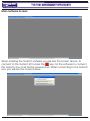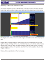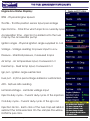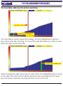
1
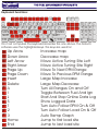
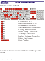
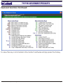
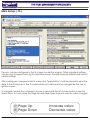
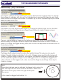
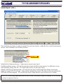
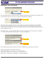
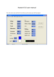
Engine Management Systems
Software User Manual
MFI X and PRO X
THE FUEL MANAGEMENT SPECIALISTS
Fuel Management System
Index
Keyboard Functions
Page #
1
Main software screen
3
Active display panel
5
The fuel map
The fuel map
- Changing injector time
The fuel map - Moving RPM ranges
6
7
8
The ignition map
The ignition map - Trigger degree
9
11
F5 Configuration screen
12
Water temp correction
Air temp correction
Battery voltage correction
17
18
19
Micro staged fuel map
20
Online data logging
21
Saving a map
Load a map onto ECU
22
23
Extra features
24
All Specifications Subject to Change without Notification
Manual Version 09.08 2009/08/25
THE FUEL MANAGEMENT SPECIALISTS
Fuel Management System
Keyboard Functions:
Esc
F1 F2 F3 F4 F5 F6 F7 F8 F9 F10 F11 F12
~ 1 2 3 4 5 6 7 8 9 0 - + Back
TAB Q W E R T Y U I O P [ ] \
CAPS A S D F G H J K L ; “ ENTER
SHIFT Z X C V B N M < > ? SHIFT
Ctrl Win Alt
Alt
Ctrl
Print Sc
Scroll Pause
Page
Insert Home Up
Delete End
Page
Down
/
7 8
4 5
1 2
0
Num
Lock
* 9
+
6
3
Del
Enter
On most computers the keyboard looks like the one above. The Gotech
software uses the highlighted keys. The keys are used for:
Page
Up
Page
Down
Insert
Delete
A
I
L
S
1
2
3
Home
End
Up Arrow
Down Arrow
Left Arrow
Right Arrow
Page Up
Page Down
Insert
Delete
A
I
L
S
1
2
3
Home
End
All Specifications Subject to Change without Notification
Increase map
Decrease map
Move Active Tuning Site Left
Move Active Tuning Site Right
Move To Next RPM Range
Move To Previous RPM Range
Large Map Increase
Large Map Decrease
Turn All Ranges On and Off
Toggle Between Fuel And Ign
Start And Stop Online Data Log
Show Logged Data
Turn Auto Follow RPM On & Off
Turn Auto Follow Load On & Off
Auto Ramp Graph
Jump to first load site
Jump to last load site
Manual Version 09.08 2009/08/25 Page 1
THE FUEL MANAGEMENT SPECIALISTS
Fuel Management System
Keyboard Functions Continued:
Esc
F1 F2 F3 F4 F5 F6 F7 F8 F9 F10 F11 F12
~ 1 2 3 4 5 6 7 8 9 0 - + Back
TAB Q W E R T Y U I O P [ ] \
CAPS A S D F G H J K L ; “ ENTER
SHIFT Z X C V B N M < > ? SHIFT
Ctrl Win Alt
Alt
Ctrl
F1
F2
F3
F4
F5
F6
F7
F8
F9
F1
F2
F3
F4
F5
F6
F7
F8
F9
SPACE BAR
Print Sc
Scroll Pause
Page
Insert Home Up
Delete End
Page
Down
/
7 8
4 5
1 2
0
* 9
+
6
3
Num
Lock
Del
Enter
Connect To ECU
Disconnect From ECU
Load Map Onto ECU
Save Map Onto Hard Drive
Configuration Screen
Water Temp Correction
Air Temp Correction
Battery Voltage Correction
Micro Fuel Screen
Mark Position
Full Details On These Key Commands Will Be Discussed Throughout This
Manual.
All Specifications Subject to Change without Notification
Manual Version 09.08 2009/08/25 Page 2
THE FUEL MANAGEMENT SPECIALISTS
Fuel Management System
Keyboard Functions Continued:
To view the key commands in the Gotech software simply press the M key.
All Specifications Subject to Change without Notification
Manual Version 09.08 2009/08/25 Page 3
THE FUEL MANAGEMENT SPECIALISTS
Fuel Management System
Main Software Screen:
When entering the Gotech software you will see the screen above. To
connect to the Gotech ECU press the F1 key. For the software to connect,
the Gotech ecu must first be powered up. Whilst connecting to the Gotech
ecu you will see the screen below.
All Specifications Subject to Change without Notification
Manual Version 09.08 2009/08/25 Page 4
THE FUEL MANAGEMENT SPECIALISTS
Fuel Management System
Main Software Screen:
After connecting to the Gotech ecu you will see the screen below.
Press the F Key to display the fuel and ignition screen.
All Specifications Subject to Change without Notification
Manual Version 09.08 2009/08/25 Page 5
THE FUEL MANAGEMENT SPECIALISTS
Fuel Management System
Anatomy of the main software screen:
The main software screen is divided into 4 sections. These sections are the
Fuel Map, Ignition Map, Engine Ecu status and the basic Key Commands.
Fuel Map
Engine ECU Status
Ignition Map
Key Commands
The Engine Ecu status shows current engine conditions. The items displayed
are:
Engine RPM, Throttle position, Total injector time, Acceleration time, Total
ignition angle, Voltage to the ecu, Manifold pressure, Air temp, Water temp,
Ignition pot, Fuel pot, AFR, Lambda Voltage, Injector duty cycle, Coil duty
cycle, Engine number of cylinders, Injector time factor, Ignition divide and
Trigger degrees.
These will be explained on the next page.
All Specifications Subject to Change without Notification
Manual Version 09.08 2009/08/25 Page 6
THE FUEL MANAGEMENT SPECIALISTS
Fuel Management System
Engine Ecu Status Display:
RPM - Physical Engine Speed
Throttle - Throttle position sensor input percentage
Injector time - Total time which injector is currently open
Acceleration time - injector ms added onto the fuel
map by the accelerator pump
Ignition angle - Physical ignition angle supplied to coil
Voltage - Voltage reading for power input to ecu
Pressure - Manifold pressure, measured in kpa
Air temp - Air temperature input, measured in ‘c
Fluid temp - Fluid temp input, measured in ‘c
Ign pot - Ignition angle subtracted
Fuel pot - Inj time percentage added or subtracted.
AFR - Air/Fuel ratio reading
Lambda Voltage - Lambda voltage input
Injector duty cycle - Current duty cycle of the injectors
Coil duty cycle - Current duty cycle of the ign coil
Injection factor - Each click of the fuel map will add or
subtract the total selected. On the sample this will be
0.058ms per click.
All Specifications Subject to Change without Notification
Manual Version 09.08 2009/08/25 Page 7
THE FUEL MANAGEMENT SPECIALISTS
Fuel Management System
The Fuel Map: (Moving the Active Load Site)
Active Load Site
Active Load Site Of Tuning
Load Sites
The Fuel Map is used to setup the fueling. The bar highlighted in green is
the active load site of tuning. To move the load site where you want to tune
press the right or left arrow key.
Active Load Site Of Tuning
When pressing the right arrow key you will notice the highlighted bar moving
to the right. The same effect will be archived when pressing the left arrow
key. The active load site of tuning will then move to the left.
All Specifications Subject to Change without Notification
Manual Version 09.08 2009/08/25 Page 8
THE FUEL MANAGEMENT SPECIALISTS
Fuel Management System
The Fuel Map Continued: (Changing the inj time)
Injector time
Active Load Site Of Tuning
To increase or decrease the fueling, move the active load site of tuning to
the preferred place. Then press the Up Arrow to increase the injector time
and the down arrow to make it less.
Injector time
Active Load Site Of Tuning
When pressing the Up Arrow you will notice the injector time going up. The
same effect will be archived when pressing the down arrow. You will then
notice the injector time moving down.
All Specifications Subject to Change without Notification
Manual Version 09.08 2009/08/25 Page 9
THE FUEL MANAGEMENT SPECIALISTS
Fuel Management System
The Fuel Map Continued: (Moving RPM Ranges)
Current RPM Range
The fuel maps are sorted in RPM ranges. So in actual fact there is 32 Load
sites every RPM range. On a 4 cylinder engine the maps are tunable on
every 500rpm. To move to the next RPM range press the Page UP key. To
move to the previous RPM range press the Page Down key.
Current RPM Range
You will see the RPM range move up when pressing the Page Up key.
All Specifications Subject to Change without Notification
Manual Version 09.08 2009/08/25 Page 10
THE FUEL MANAGEMENT SPECIALISTS
Fuel Management System
The Ignition Map: (Toggle between fuel and ignition)
Active Load Site
To toggle between the fuel and ignition screen, press the I Key.
Active Load Site
By pressing the I Key you will notice the active load site moving to the
bottom. The ignition screen is now active.
All Specifications Subject to Change without Notification
Manual Version 09.08 2009/08/25 Page 11
THE FUEL MANAGEMENT SPECIALISTS
Fuel Management System
The Ignition Map Continued:
Ignition Angle
Active Load Site Of Tuning
The ignition map works on the same principle as the fuel screen. The up
arrow will increase the ignition angle and the down arrow will make it less.
The left and right arrow keys will move the active load site of tuning and the
Page Up/Page Down keys will toggle between RPM ranges. When the
ignition angle is increased then the ignition timing is being advanced.
Ignition Angle
All Specifications Subject to Change without Notification
Manual Version 09.08 2009/08/25 Page 12
THE FUEL MANAGEMENT SPECIALISTS
Fuel Management System
Water temp correction screen: ( F6 )
Enrichment %
Current water temperature
Current load site of tuning
The water temperature correction map is used to enrich the engine when cold. The main
tuning principle is the same as on the fueling map, except that the water temp correction
is not RPM based.
The Green highlighted bar is the current load site of tuning. The red bar is where engine
temperature is currently situated.
The left and right arrow keys are used to move the current load site of tuning between the
temperature ranges. The up and down arrow keys are used to increase and decrease the
enrichment percentage.
Move Current Load Site Of Tuning Left
Move Current Load Site Of Tuning Right
Decrease enrichment percentage
Increase enrichment percentage
All Specifications Subject to Change without Notification
Manual Version 09.08 2009/08/25 Page 13
THE FUEL MANAGEMENT SPECIALISTS
Fuel Management System
Air temp correction screen: ( F7 )
Enrichment %
Current air temperature
Current load site of tuning
The air temperature correction map is used to enrich the engine when the air temp is
cold. The main tuning principle is the same as on the fueling map, except that the air
temp correction is not RPM based.
The Green highlighted bar is the current load site of tuning. The red bar is where the air
temperature is currently situated.
The left and right arrow keys are used to move the current load site of tuning between the
temperature ranges. The up and down arrow keys are used to increase and decrease the
enrichment percentage.
Move Current Load Site Of Tuning Left
Move Current Load Site Of Tuning Right
Decrease enrichment percentage
Increase enrichment percentage
All Specifications Subject to Change without Notification
Manual Version 09.08 2009/08/25 Page 14
THE FUEL MANAGEMENT SPECIALISTS
Fuel Management System
Battery Voltage correction screen: ( F8 )
Enrichment %
Current battery voltage
Current load site of tuning
The battery voltage correction map is used to enrich the engine when the battery voltage
drops. The main tuning principle is the same as on the fueling map, except that the
battery voltage correction is not RPM based.
The Green highlighted bar is the current load site of tuning. The red bar is where the
battery voltage is currently situated.
The left and right arrow keys are used to move the current load site of tuning between the
voltage ranges. The up and down arrow keys are used to increase and decrease the
enrichment percentage.
Move Current Load Site Of Tuning Left
Move Current Load Site Of Tuning Right
Decrease enrichment percentage
Increase enrichment percentage
All Specifications Subject to Change without Notification
Manual Version 09.08 2009/08/25 Page 15
THE FUEL MANAGEMENT SPECIALISTS
Fuel Management System
Micro staged fuel map: ( F9 )
Enrichment ms
Current load site
Current load site of tuning
The micro staged fuel map is used to control a second set of fuel injectors. The main
tuning principle is the same as on the fueling map, except that the micro staged map is
not RPM based.
The Green highlighted bar is the current load site of tuning. The red bar is the active load
site.
The left and right arrow keys are used to move the current load site of tuning between the
load sites. The up and down arrow keys are used to increase and decrease the injector
time.
Move Current Load Site Of Tuning Left
Move Current Load Site Of Tuning Right
Decrease injector time
Increase injector time
All Specifications Subject to Change without Notification
Manual Version 09.08 2009/08/25 Page 16
THE FUEL MANAGEMENT SPECIALISTS
Fuel Management System
Main Setup: ( F5 )
The ecu can be configured in the f5 screen to suite the engine. Other important settings
can also be changed here, eg Acceleration pump, General purpose outputs and launch
control settings.
After making any changes to the f5 screen the “Apply Button” must be clicked to save the
data to the Gotech ecu. The f5 screen does not make real time changes like the fuel or
ignition screen.
To navigate around the computer’s mouse is used and the left mouse button is used to
select items. In most cases the Page Up and Page Down keys are used to make changes.
Page
Up
Page
Down
Page Up
Page Down
All Specifications Subject to Change without Notification
Increase value
Decrease value
Manual Version 09.08 2009/08/25 Page 17
THE FUEL MANAGEMENT SPECIALISTS
Fuel Management System
Main Setup: ( F5 )
Trigger mode
The main setup screen is the most critical part of the Gotech software. Here you can
select the trigger input and engine setup.
The configuration modes available are: (These are explained in the wiring installation manual)
To select a mode, click on the preferred mode to use with the left mouse button.
Mode 0 - Trigger Per Event, No TDC; Distributor only.
Mode 1 - Trigger Per Event, Plus TDC; Distributor only.
Mode 2 - Trigger Per Event, Plus TDC; Distributor or coil packs (Full sequential compatible)
Mode 3 - Distributor 24 tooth sensor, Plus TDC; Distributor or coil packs
Mode 4 - Crank angle input 60 -2; Coil packs (Full sequential compatible with TDC)
Mode 5 - Crank angle input 60 -2; Distributor only.
Mode 6 - Crank angle input 36 -1; Coil Packs (Full sequential compatible with TDC)
Mode 7 - Distributor 24-2 sensor; Distributor or coil packs (Full sequential compatible)
Click here
The full sequential mode can be enabled by left clicking on the drop down list and then
using the left mouse button to select “Enabled”. The full sequential mode can only be
selected in certain applications. These have been pin pointed above.
All Specifications Subject to Change without Notification
Manual Version 09.08 2009/08/25 Page 18
THE FUEL MANAGEMENT SPECIALISTS
Fuel Management System
Main Setup: ( F5 ) Continued
Click here
The engine cylinders value is used by the ecu to determine the engine setup. To change
the number of cylinders, left click on the Cylinders block and use the Page Up and Page
Down buttons to change the number of cylinders. Eg on a four cylinder engine you would
want this value to be four.
Click here
Ed
ge
i ng
R is
Rising Edge
ge
Ed
0
g
Click here
lil n
Fa
+
Falling Edge
The Gotech ecu has a built in RPM limiter. To change the RPM limit left click on the RPM
limit value and use the Page Up and Page Down buttons to make it higher or lower.
The ecu can be setup to trigger on the falling or rising edge when using a distributor.
Before making a change it is best to inspect the distributor and see for which mode it is
setup. To change the trigger sensing value, left click on the drop down list and left click on
the preferred setup.
Click here
The trigger tooth value is used to match the ignition timing. This value is only used in
Mode4, Mode5, Mode6 and Mode7. On a 60 -2 trigger wheel each tooth change will
make a 6’ ignition angle change on the engine. To advance the ignition timing go less
and to retard the ignition timing increase the trigger tooth. To change the trigger tooth
value, left click on the trigger tooth value and use the Page Up and Page Down key to
make a change.
Hint:
A quick and simple way to estimate the trigger tooth value is to
turn the engine to TDC and count the amount of teeth from
the sensor to the gap. At TDC the gap will be past
the sensor.
In this case the trigger tooth will be 14.
All Specifications Subject to Change without Notification
Manual Version 09.08 2009/08/25 Page 19
THE FUEL MANAGEMENT SPECIALISTS
Fuel Management System
Load Input: ( F5 )
The load input screen is used to select the primary inputs, calibrate the manifold pressure
sensor and calibrate the throttle position.
Click here
Manifold Air Pressure Sensor - Map sensor as primary input
Throttle position sensor - TPS as the primary input and the map sensor for altitude comp.
Mix between Map and TPS - TPS and Map sensor as primary input.
Mixed until TPS not appropriate - TPS as primary input until boost then Map as primary.
Map for load & TPS for accell - Map sensor as primary input, TPS only for the accell pump.
TPS Main & Map staged - TPS as primary input, Map sensor only for the micro fueller.
Hint: For a normally aspirated vehicle with mild camshafts; Map for load& TPS for accell
pump is a good choice.
All Specifications Subject to Change without Notification
Manual Version 09.08 2009/08/25 Page 20
THE FUEL MANAGEMENT SPECIALISTS
Fuel Management System
Load Input: ( F5 ) Continued
Click here
The load interpolation method enables / disables interpolation between the load sites. The
most effective way to run the ecu is with the interpolation enabled.
Click here
The sensor type configures the ecu for the type of map sensor that has been installed.
When using a standard map sensor the load start and load interpolation values will be
active. When selecting any one of the optional items, the ecu will automatically scale the
fuel and ignition maps
The Gotech ecu comes standard with a 2.5 Bar map sensor. This map sensor is capable
of 1.5 Bar (21psi) positive pressure and 1 Bar (14 psi) negative
Click here
Click here
The load start and load increment is used to calibrate the map sensor or the TPS.
When running map only these values are:
Normally aspirated - Load start 1, Load increment 3
Turbo Up to 1 Bar boost - Load start 1, Load increment 6
Turbo Up to 1.5 Bar boost - Load start 1, Load increment 8
All Specifications Subject to Change without Notification
Manual Version 09.08 2009/08/25 Page 21
THE FUEL MANAGEMENT SPECIALISTS
Fuel Management System
Fuel: ( F5 )
The fuel screen is used for basic injection setup and fuel trimming. The individual fuel
trimming should only be used on full sequential applications.
Click here
The injection time modifier changes the steps in which fuel map can be programmed. Eg
each click up will make a 0.058ms change on the fuel map.
Mode
Batch or Phased
Full sequential
Batch or phased with
big injectors
Injection Time modifier suggested
0.058ms
0.087ms
0.029ms
All Specifications Subject to Change without Notification
Manual Version 09.08 2009/08/25 Page 22
THE FUEL MANAGEMENT SPECIALISTS
Fuel Management System
Fuel: ( F5 )
Click here
The ignition divide factor is only active in batch firing modes. The ignition divide factor
divides the injection per engine cycle.
Engine Cylinders
1
2
3
4
5
6
8
Ignition divide suggested
1
1
1
2
1
3
4
When running in full sequential mode each cylinder can be trimmed individually. The
trimming can be done either in percentage or injector time. You can then add a
percentage onto the injection time or add a physical value.
Move Current Load Site Of Tuning Left
Decrease injector time or percentage
Move Current Load Site Of Tuning Right
Increase injector time or percentage
All Specifications Subject to Change without Notification
Manual Version 09.08 2009/08/25 Page 23
THE FUEL MANAGEMENT SPECIALISTS
Fuel Management System
Fuel: ( F5 )
Click here
The startup fueling setting can be used to add more fuel whilst cranking the engine. This
setting is only active when the engine temperature is below 50’c. In most cases around
1.5ms is more than sufficient fo a good startup. When running big injectors this value must
be changed accordingly to prevent engine over fueling.
Click here
The micro fuel mode configures the micro fueller’s ignition divide. The micro fueller can be
setup to use the same ignition divide as the main injectors or be setup to fire differently.
The recommended setting is [Use Ignition Divide]
All Specifications Subject to Change without Notification
Manual Version 09.08 2009/08/25 Page 24
THE FUEL MANAGEMENT SPECIALISTS
Fuel Management System
Ignition: ( F5 )
The ignition screen controls basic ignition options.
Trigger Degrees:
The trigger degrees is the degrees before TDC at which the ecu is triggered. In most cases
this would be 40 degrees. When running a trigger degree of 40 the maximum ignition
timing achievable will also be 40 degrees. This value should never be above 55’.
Coil charge time:
The ecu can control the time for which the ignition coil will be charged before discharge
will take place. There are certain conditions that must be taken into consideration when
charging the ignition coil. These are; Number of Cylinders and maximum engine RPM.
Max Charge time =
(
120000
Max RPM x Cylinders
)
– 0.5
Cold Ignition Advance:
The ignition timing can be advanced whilst cranking the engine to aid cold starting. In
most cases this is not required, thus this feature is locked for feature use.
Rotary Trailing Degrees:
On Rotary engines the leading and trailing spark plugs are not fired at precisely the same
time. The ignition trail can be set be suite these engines. The recommended setting is 6’.
All Specifications Subject to Change without Notification
Manual Version 09.08 2009/08/25 Page 25
THE FUEL MANAGEMENT SPECIALISTS
Fuel Management System
Acceleration: ( F5 )
The acceleration screen controls basic acceleration pump options and setup.
Acceleration sensitivity:
The Acceleration sensitivity configures how sensitive the Acceleration pump should be. The
lower the value, the more sensitive the pump. Normally around 10% is a good place to
start. There are two settings, one for the accel pump and one for the cold accel pump.
The cold accel pump adds a percentage onto the normal accel pump to aid cold rev
up. If either of the sensitivities are set too low the accel pump may switch when it is not
required and over fuel the engine.
The accelerator fueling map adds fuel onto the main
fuel map to aid rev up conditions. This map adds fuel
in a ms value.
The accelerator value added can be seen on the main
fuel screen. Normally the accel map should only be
activated after full tuning has been done.
Move Current Load Site Of Tuning Left
Move Current Load Site Of Tuning Right
Decrease accelerator pump time
Increase accelerator pump time
All Specifications Subject to Change without Notification
Manual Version 09.08 2009/08/25 Page 26
THE FUEL MANAGEMENT SPECIALISTS
Fuel Management System
Acceleration: ( F5 )
The cold accelerator map adds a percentage onto the
acceleration map to aid rev up conditions when the engine
is cold.
The cold acceleration map is based on temperature
(left to right where the right hand is cold) and percentage.
The accelerator value added can be seen on the main
fuel screen. Normally the accel map should only be
activated after full tuning has been done.
Click here
The acceleration high rpm decay controls how long the acceleration pump should be
kept activated before the fueling returns back to normal.
Click here
All Specifications Subject to Change without Notification
Manual Version 09.08 2009/08/25 Page 27
THE FUEL MANAGEMENT SPECIALISTS
Fuel Management System
Lambda: ( F5 )
The lambda screen is used to setup the lambda sensor and select lambda type.
Click here
Lambda sensor type:
The type of lambda input can be selected
These can be from narrow band sensors to
wideband analogue inputs.
Lambda Target AFR:
The AFR target can be selected by using the
mouse and clicking on the preferred value.
The AFR and lambda values are displayed on
the bottom of the screen.
Each lambda sensor uses a different lookup
table for the AFR.
All Specifications Subject to Change without Notification
Manual Version 09.08 2009/08/25 Page 28
THE FUEL MANAGEMENT SPECIALISTS
Fuel Management System
Lambda: ( F5 )
Click here
The lambda start RPM is the RPM at which the closed loop lambda control will start
working. Normally the lambda will get a good reading above around 2000rpm.
Click here
The lambda stop load is the load site at which the closed loop lambda control will stop
working. Normally you do not want the lambda to operate past half throttle or in boost. The
lambda sensor should only be used to optimize cruising mixtures.
Click here
The lambda response time determines how long the ecu should take before making a
change to the engine’s mixture. The ecu should not be able to change the mixture too
quickly, the ECU should have enough time to take a couple of samples and then change
the mixture accordingly.
Click here
The lambda modification limit controls the maximum allowable fuel change. The lambda
limit is in ms.
All Specifications Subject to Change without Notification
Manual Version 09.08 2009/08/25 Page 29
THE FUEL MANAGEMENT SPECIALISTS
Fuel Management System
Launch Control: ( F5 )
The launch control screen is used to setup the launch control RPM and time limit.
Click here
The launch RPM limit is where the engine will limit whilst the launch control is activated. This
value is fully configurable.
Click here
Launch Retard Limit. After de-activating the launch control this is the time that it will take for
the ecu to start advancing the ignition timing back to it’s original state.
All Specifications Subject to Change without Notification
Manual Version 09.08 2009/08/25 Page 30
THE FUEL MANAGEMENT SPECIALISTS
Fuel Management System
Launch Control: ( F5 )
Move Current Load Site Of Tuning Left
Move Current Load Site Of Tuning Right
Advance ignition timing closer to original
Retard Ignition Timing
The launch ignition map is used to retard the ignition timing whilst the launch control is
activated. The ignition timing can be kept retarded for a certain amount of time and then
brought back to the original position as desired.
The Launch fuel map can be used to enrich
the engine whilst the launch control has been
activated. The enriched mixture will help spool
up the turbo and cool the exhaust housing.
Be aware not to add too much fuel as it may
cause the engine to over fuel and misfire.
Move Current Load Site Of Tuning Left
Move Current Load Site Of Tuning Right
Decrease Injector time
Increase injector time
All Specifications Subject to Change without Notification
Manual Version 09.08 2009/08/25 Page 31
THE FUEL MANAGEMENT SPECIALISTS
Fuel Management System
GPO Control: ( F5 )
The GPO screen controls all the GPO outputs and their functionality.
All Specifications Subject to Change without Notification
Manual Version 09.08 2009/08/25 Page 32
THE FUEL MANAGEMENT SPECIALISTS
Fuel Management System
Advanced: ( F5 )
The advanced screen controls the double rpm, cooling fan, noise filter and altitude
settings.
Double RPM Range:
The double RPM range setting is used for engines
that need tuning ability at higher RPM ranges.
Click here
Eg. When enabled on a eight cylinder engine
each RPM range will be 500rpm and you can
map up to 13500rpm instead of 6750rpm.
The Altitude correction value is only available when running in TPS mode. The Gotech ecu
can then add a percentage onto the main fuel map to enrich the engine when going to
the coast or lean it out when going up to altitude.
The altitude retard value is used to retard the ignition timing when going to the coast from
altitude. This setting is only available when running in TPS mode.
Noise filter strength. The noise filter should always be disabled, except when triggering the
ecu from coil negative and only running the fuel.
Cooling fan. The cooling fan can be switched on at a temperature and then off again
once it has cooled down. Both these values can be set to any temperature.
All Specifications Subject to Change without Notification
Manual Version 09.08 2009/08/25 Page 33
THE FUEL MANAGEMENT SPECIALISTS
Fuel Management System
Summary: ( F5 )
The summary page simply shows all the selected values on one page for a quick
reference. You cannot change any values on this page, they can only be viewed.
After making any changes on the f5 setup screens remember to press the apply button to
save them to the Gotech ecu.
All Specifications Subject to Change without Notification
Manual Version 09.08 2009/08/25 Page 34
THE FUEL MANAGEMENT SPECIALISTS
Fuel Management System
Save and Upload maps:
The Gotech software is capable of saving the current map from your Gotech ECU to the
hard drive of your notebook / desktop.
To save your current map from the ECU press the F4 button. You can then enter a file
name into the block and simply click on the save button. Wait for the map to save
completely before resuming with any tuning.
To load a map from your computer’s hard drive press the F3 button. After the load file
window appears select the preferred map to upload and click on the load button. This will
then transfer the map from your computer’s hard drive to the Gotech ECU. Wait for the
map to load completely before resuming with any tuning.
All Specifications Subject to Change without Notification
Manual Version 09.08 2009/08/25 Page 35
THE FUEL MANAGEMENT SPECIALISTS
Fuel Management System
Online data logging:
The Gotech software is capable of online data logging. The online data log can be used
for basic fault finding. To start logging press the L key. To stop the logging process press the
L key again. To view the logged data press the S key.
All Specifications Subject to Change without Notification
Manual Version 09.08 2009/08/25 Page 36