1
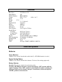
Fairwinds
Sailing and Recreational Society
Standard Operating Procedures
Jolie Systems
Revised: August 2014
1
Document Revision History
August, 2014 : fueling, Webasto heater , electrical systems update
June, 2013 : pre/post sailing checklists and anchoring procedure updated
January 23, 2005 – created
2
JOLIE SYSTEMS ................................................................................................. 1
SKIPPER SIGNATURE SHEET ........................................................................... 6
OVERVIEW .......................................................................................................... 8
ELECTRICAL SYSTEMS ..................................................................................... 8
HOUSE BATTERIES
ENGINE STARTING BATTERY
BATTERY SELECTOR
BATTERY CHARGING
12 VOLT BREAKER PANEL
12 VOLT SYSTEMS NOT WIRED THROUGH A BREAKER
120V BREAKER PANEL
SHORE POWER
WATER HEATER
ELECTRICAL OUTLETS
ELECTRIC BILGE PUMP
STEREO / CD CHANGER
DEPTH, SPEED, LOG AND WATER TEMPERATURE
INTERIOR LIGHTING
NAVIGATION AND DECK LIGHTING
VHF RADIO
GPS
8
9
9
10
10
11
11
12
14
14
14
14
15
16
16
16
16
ENGINE / PROPULSION SYSTEMS ................................................................. 17
OVERVIEW
STARTING
RUNNING
STOPPING
EMERGENCY STARTING
EMERGENCY STOPPING
OVERHEATING
OIL PRESSURE FAILURE
ALTERNATOR FAILURE
FUEL
ENGINE OIL
ENGINE COOLANT (FRESH)
COOLING WATER (SEA WATER)
TRANSMISSION
SHAFT SEAL
PROPELLER
17
18
18
18
19
19
19
20
20
21
21
21
21
23
23
23
DOMESTIC SYSTEMS ....................................................................................... 23
ICE BOX
FRESH WATER
SINKS AND DRAINS
HEAD AND HOLDING TANK
23
23
24
24
3
SHOWER
GALLEY STOVE
PROPANE
CABIN HEAT
BUNKS AND CUSHIONS
25
26
26
26
27
RIGGING ............................................................................................................ 28
SAILS
RUNNING RIGGING
DOCKING LINES, FENDERS, ETC.
28
28
28
DECK SYSTEMS................................................................................................ 28
STEERING
THROUGH-HULL AND VENT LOCATIONS
STORAGE
ANCHORING
BILGES AND BILGE PUMPS
STERN-TIE LINE
28
29
29
30
31
31
SAFETY AND MISCELLANEOUS ..................................................................... 32
FLARES
LIFE VESTS – PFDS – FLOATING THINGS
FIRE EXTINGUISHERS
TOOLS AND SPARE PARTS
LIGHTENING PROTECTION
REVERSE POLARITY LIGHT
PROPANE ALARM
ENGINE PANEL ALARMS
DOCUMENTATION, LOG AND OPERATING MANUALS
DEHUMIDIFYING AND WINTER STORAGE
THE BAR
MISCELLANEOUS BOAT EQUIPMENT
CLEANING SUPPLIES AND EQUIPMENT
BARBEQUE
LOCKS AND KEYS
32
32
32
33
33
33
33
34
34
34
35
36
36
36
36
PRE-SAILING CHECKLIST ............................................................................... 37
POST SAILING CHECKLIST ............................................................................. 39
4
Skipper Signature Sheet
All skippers must sign below to indicate that they have read the complete “Jolie SOP”
and relevant section in the “Manual Book” Skippers must also read the Pearson Owner’s
Manual.
Name
Date
Signature
5
Overview
Boat Type:
Hull Number:
Hull Id. Number:
Length
Beam:
Height:
47’ 6”
Draft:
Displacement:
Ballast:
Sail Area:
Hull Speed:
Fuel Capacity:
Potable Water:
Aft Tank:
V-berth Tank:
Hot Water:
Engine:
Fuel consumption
Holding Tank:
Rudder:
VHF
1988 Pearson 33-2
140
PEA88I40F788
LOA: 32’ 6”
11’ 0”
LWL: 26’ 3”
5’ 11” (fin keel)
12,441 lbs
4,000 lbs
515 sq ft.
6.9 kts
18.5 US gal or 70 liters
20 US gal (75 liters)
24 US gal (90 liters)
6 US gal (22 liters)
Yanmar 2GM20F 18hp at 3600rpm
2.4 liter/hour @ 2800 rpm
14.5 US gal
Spade
call sign: CFN6073; MMSI#: 316022134
Electrical Systems
Batteries
House Batteries
(Number 2 on selector) located under after berth (2 x 6V/240Ah batteries in series)
Engine Starting Battery
(Number 1 on selector) located in the lazarette. To be used for starting engine only.
Battery Selector
Location: The selector switch is located in after cabin.
Warning: NEVER turn the battery selector through the “OFF” position while the
engine is running. If the “OFF” position is selected while the engine is running, the
alternator diodes may be seriously damaged. Switch battery selector through the
“BOTH” position to select batteries.
6
Use: To start the engine when leaving dock, select battery #1 (Starting battery). Once the
engine has started, select battery #2 (house batteries), by turning the selector through the
“BOTH” position and leave it there for the duration of your voyage. The engine may be
started from the house batteries without detrimental effect to them, but using the starting
battery at least once per trip will lengthen the life of the starting battery.
After Use: Battery selector switch must be turned to the “OFF” position when finished
using boat.
Battery Charging
Location: There is a permanent, “smart” ferro-resonant charger located under the aft
berth. The breaker for the charger is located on the shore power portion of the breaker
panel. This system may only be used when connected to shore power. The charger is
designed to not overcharge the batteries, so the 110v charger breaker should be left in the
ON position when connected to shore power.
Jolie is equipped with a digital battery separator that charges both batteries while the
engine is running.
Use: The built-in battery charger may be used at any time while connected to shore
power. If running the engine only to charge the batteries, do not idle the engine, run at
about 1200 to 1500 rpm to ensure proper lubrication.
After Use: If connected to shore power leave the charger breaker in the ON position.
When not connected to shore power the breaker should be in the OFF position.
Check electrolyte levels in “House” batteries regularly and top up with distilled water
when needed.
Breaker Panels / Power Distribution
The following is a list of equipment that is isolated by each breaker.
12 Volt Breaker Panel
Breaker Name
Cabin Lights
Running Lights
Anchor Light
Nav / Com
Instruments
Sump Pump / Water Pressure
Stereo
Head Discharge
Spreader
Propane
Systems Controlled
All interior lights
Running lights (sail and steaming light)
Anchor light (LED)
VHF
Cockpit instrument cluster
Shower / head sump pump (On/Off switch is in the head)
Turns on water pressure system (NEVER USE if the water
tanks are empty)
Stereo & CD changer
Operates holding tank pump
Spreader lights (shines on foredeck)
Operates propane electric shut-off valve
7
Other 12 V breakers:
Electric windlass
Electric head
Webasto heater fuse
Aft cabin
In the head, next to “holding tank full” light
Lazarette under the heater
12 Volt Systems not wired through a Breaker
- Auxiliary 12 Volt plug-in (cigarette lighter type).
- Bilge pump (pump operated by switch above breaker panel and will operate even when
battery selector is in OFF position).
- Clock on Webasto controller /timer (will run with battery selector in OFF position).
- Propane alarm /CO detector (will NOT operate with battery selector in OFF position).
- Battery status monitor
120V Breaker Panel
Breaker Name
Main Breaker
Reverse Polarity Light
Outlets
Appliances / Water Heater
Accessories / Battery
Charger
Systems Controlled
Turns shore power on to the rest of the panel
Light turns on if polarity reversed
Electrical outlets
Turns on the water heater
Turns on the built-in battery charger.
Electrical systems power budget
DEVICE
Power draw
Windlass
35A (420W)
Electric head
18A (200W)
Head discharge
16A (190W)
Webasto heater
8 A (90W)
3.2A (40W)
1.2A (15W)
Water pressure pump
4.0A (48W)
Running lights
1.7A (20W) sail
2.5A (30W) power
Propane solenoid
1A (12W)
Stereo
1A (12W)
Cabin lights
1.4A(16W)
Anchor light
Nav/Com
Instruments
0.2A (2.5W)
0.5A (6W)
0.2A (2.5W)
8
Notes
use it ONLY while the engine is running
high amperage, but only minutes per day in use.
use it while the engine is running
- glow plug pre-heating (initial ~20 seconds)
- first stage heat
- temperature maintenance mode (low speed fan).
while the pump is running
w/ all white lights ON. Note: white cabin lights are a LED ty
Red incandescent lights draw 1Amp each.
Individual Electrical Systems
Shore Power
Jolie has a 120V - 30 Amp system (round plug). A gender-bender is required to connect
to 15 Amp shore power.
Connector Location: The shore power connector is located under the helmsman’s seat
(aft cockpit port side).
Shore power breakers: The forward section of the breaker panel is for shore power
systems. These include electrical outlets, the water heater and battery charger.
Cable: The shore power cable is kept in a canvas bag in the lazarette. Also in the bag are:
gender-bender fittings, Velcro tabs for supporting the cable and a rubber bungee for
supporting the cable at the jetty power source. Always store the cable on board, never
leave it on the jetty. When connecting to shore power, always “work towards the source”.
This means connect the boat end first, secure the cable run and finally connect to the
shore power source. Always make this connection last so the cable is never live until it is
all set-up.
After Use: When finished with Jolie, leave her connected to shore power at Tsehum
Harbour.
9
Water Heater
Location / Specifications: Six gallon hot water tank is located under the holding tank,
accessed from the lazarette. Water is heated by 120V (shore power) electric heater
element and also by engine heat. The breaker is located on the shore power breaker panel.
Use: Hot water may be turned on whenever connected to shore power.
Warning: Do not turn on the water heater breaker when the tanks are empty. The
heater must be full of water before 110v power is applied in order to avoid damage
to the heater element. You can confirm there is water in the system by turning on
any tap while system is pressurized. In addition to the shore power water heater, the
water also automatically heats whenever the engine is running.
After Use: Turn off hot water breaker.
Electrical outlets
Location: Electrical outlets are located throughout the cabin.
Use: Outlets may only be used when connected to shore power. To use, turn on the outlet
breaker on the shore power breaker panel. The outlets in the galley and head are groundfault protected.
After Use: Turn off the outlets at the shore power breaker panel.
Electric Bilge Pump
Location / Specifications: The electric bilge pump is located under the deck panel,
amidships, next to the liquor cabinet. It has a single pick-up located amidships, about ½
inch from the bilge bottom. Operating switch is on the instrument panel.
Flow rate is: 800 gph
Automatic operation: Leave the switch in the Automatic position. The automatic bilge
pump runs directly from the battery.
Manual operation: Select Manual on bilge pump selector switch. Switch back to
Automatic when the pump loses suction.
Stereo / CD changer
Location / Specifications: Stereo and CD changer are located port side in the cabin.
Speakers are located in the cabin and in the cockpit. Fader control may be used to select
between these.
Use: Refer to manual for operation. Stereo breaker must be on.
After Use: The CD cassette must be left in the CD changer after use. The remote control
must be left on its Velcro tab after use.
Depth, Speed, Log and Water Temperature
Location / Specifications: Sensors are located in the forward bilge compartment. The
instrument displays are located on the binnacle.
Use: Turn on the instrument breaker on the breaker panel.
After Use: Turn off the instruments breaker.
10
Interior Lighting
Location / Specifications: Located throughout cabin. All interior lights operate on 12V.
Use: Lighting breaker must be on. Dome lights may be switched to either white (LED) or
red (incandescent) light.
After Use: Turn off all lighting and the breaker.
Navigation and Deck Lighting
Location / Specifications: Controlled from navigation light control panel and main
breaker panel.
Use: The navigation light control panel shows various light configurations.
Configurations are running lights (sail and motor) anchor light and foredeck light.
After Use: Turn off all lights and shut off breaker.
VHF Radio
Location / Specifications: Instrument panel / Standard Horizon Quest-plus, DSC.
Use: Refer to owners manual. Command Mic. is stored on the shelf port side; it is to be
connected to connection in cockpit.
After Use: Place Command Mic. on the port shelf, turn off Nav/Com breaker.
GPS
Location / Specifications: GARMIN hand-held type, on holder, port side, forward of the
nav station
Use: Use plug-in connected to the GPS unit, as the device feeds GPS coordinates to VHF
Radio.
After Use: Turn off GPS unit.
Battery status monitor
Location / Specifications: Instrument panel / Battery voltage and charging systems
monitor.
Use: "Three bars" (or 12.6V) is a "battery fully charged" indicator. That normally
relatively quickly falls to 12.3V (2 bars) under a load and then slowly slips to 2 bars
(12V) over time.
Once a single bar begins tp flash (<12V), it is time to recharge the battery (ie. run the
engine for an hour @ 1200 rpm or engage the battery charger, if on shore power).
The battery monitor draws a negligible current and it should be left ON at all times.
Engine / Propulsion Systems
Engine
Overview
Engine Type:
Horsepower:
Yanmar 2GMF-20
18hp @ 3600rpm
11
Basic Description:
output:75Amps.
Hour-meter:
Price:
2 Cylinder, Freshwater Cooled, Diesel Engine. Alternator
Located above breaker panel
Pay the hourly rate to the kitty located in the navigation table.
($8.00 per hour at time of publication of this SOP – refer to
website for current rates)
12
Starting
1. Check oil. Dip stick is accessed via small door in aft cabin. Engine room light switch is
below the battery selector switch (cabin lights breaker must be on to operate light). If low
-top up with 15W-40 engine oil. Spare oil is stored under port settee.
2. Check cooling water level (Check only when cold).
3. Check cooling water through-hull (normally left open) in main engine compartment.
4. Visual check. Check for obvious leaks of oil, fuel or cooling water, check alternator
and water pump belt tension, check for loose hose clamps, broken components. When
replacing companionway steps, ensure the bottom of the step is properly seated.
5. Check fuel level. Fuel tank gauge in the aft berth.
6. Place gear selector in neutral.
8. Turn on ignition and press start button.
9. Engine should turn over. Release the button as soon as engine fires steadily.
NOTE: Do not crank engine for more than 15 seconds. If engine fails to start, wait 15
seconds and try again. NEVER press the start button unless the engine is fully stopped.
11. Warm-up engine for a minute or two at high idle (~1200 rpm) – long enough to
ensure it is running smoothly; extended warm-up dockside is not necessary as diesels
don’t warm up well under no load.
VISUALLY CHECK that water is being ejected out the exhaust pipe. This indicates
correct cooling water flow.
Running
1. Select desired gear (forward – down, back – up). Always ensure engine is at idle
before changing gear.
2. The engine is rated for 3600 max rpm. It runs most comfortably at about 2800 rpm.
Running the engine between 2800 and 3000 rpm while cruising will keep it “hot” and it
will prevent build up of undesirable carbon deposits in the system.
3. Maintain a watch on engine’s rpm, listen for unusual noises, monitor engine exhaust
colour, and visually inspect quantity of water in exhaust on a continual basis. Shut engine
down if there is anything out of the ordinary.
4. The most common cause of overheating is seaweed stuck in the cooling water inlet. If
overheating occurs… shut off engine, close engine water through-hull valve and clean
water strainer (near the valve). Replace strainer, open valve and try engine again.
Stopping
1. Place throttle at idle. Allow engine to operate at a low speed for about five minutes to
cool. If engine has been used at low speed for this amount of time to moor the boat… this
will suffice.
2. Ensure gear box is in neutral.
3. Move throttle to ¾ position and allow engine to rev for about 2 seconds.
4. Move throttle to idle and pull stop lever while engine is coming down from the high
revs so that it slows and stops in one smooth motion. (this procedure will help clear
carbon from the cylinders before shutting off)
5. Switch off the ignition.
13
Emergency Starting
The engine will not start if both “Starting” and “House” batteries are drained.
Avoid putting the battery selector switch on “BOTH” position.
Emergency Stopping
1. In the case of an emergency, pull and hold the stop lever until the engine stops.
2. If the stop lever does not work, pull the stop lever mechanism on the engine.
3. If the engine still won’t stop, close the fuel shut-off valve (on the fuel tank under aft
berth). Fuel lines will need to be bled to re-start.
4. As a last resort (in case of engine run-away) pull the decompression lever until the
engine is stopped. If you use this method, fuel delivery to the engine continues until the
engine stops turning. This will result in abnormal combustion, and possibly explosion,
when the engine is next started.
Engine Emergencies
The engine alarm panel has audible and visual alarms for high water temperature
(Overheating), low oil pressure and low charging voltage (Alternator Failure). The
following actions should be carried out if the alarms sound.
Overheating
If engine overheats, STOP ENGINE IMMEDIATELY. The most likely cause is a sea
water blockage. Clean strainer /raw water inlet and try again.
Oil Pressure Failure
In case of oil pressure failure, STOP ENGINE IMMEDIATELY. Check oil level and
replenish if required. If oil level is ok, do not re-start engine. If oil level is low, (it will
have to be very low to cause a loss of oil pressure) then check for leaks prior to restarting.
Alternator Failure
If the alternator fails, you may keep running the engine. The batteries however will not be
charging during operation, and the problem should be rectified as soon as possible.
14
Engine Systems
Fuel
Location / Specifications:
-Aluminum tank, located under aft berth (70 liters, 18.5 US gal).
-Fuel gauge is located under aft berth on top of the tank.
-Fuel shut-off valve is located on the top forward edge of the fuel tank, accessed under
the aft berth.
-Deck fitting: located at the aft port corner of the deck.
Use: Fill with diesel fuel only to max. 7/8 of tank's capacity. Do not overfill to
minimize the risk of a diesel leak from the tank. Fuel consumption is about 2.4 liters per
hour at 2800 rpm.
Feel free to calculate it for a long trip and let the boat captain know what your
consumption is. The range of Jolie on a full tank is about 30 hours or about
180 nautical miles.
NOTE: The fuel gauge will not display the diesel levels below ~1/4 full. Do not run out
of fuel or you will have the joy of priming the fuel system when you fill it next.
After Use: No action required.
Engine Oil
Location / Specifications: Filled though cap on top of engine rocker cover. Oil is stored
under the aft berth on the starboard side.
Use: Use 15W-40 only, check oil level once per day during engine use.
After Use: Clean all spilled oil as if the engine compartment is your kitchen.
Engine Coolant (Fresh)
Location / Specifications: Engine coolant may be checked via the expansion tank,
located in the upper port side of the engine compartment. This is accessed from the aft
cabin (under the forward shelf).
Use: May be topped up with fresh water or anti-freeze coolant. Inform boat captain if it is
necessary to frequently top up engine coolant.
After Use: Clean any spills as if the engine compartment is your dining room.
Cooling Water (Sea Water)
Location / Specifications: Through-hull valve is located in the engine compartment,
under the companionway on the starboard side. The strainer is located just above the
through-hull valve.
Use: The through hull should be left open at all times. A visual check should be carried
out prior to boat use. The strainer should be checked / cleaned if a cooling problem arises.
A loss of cooling water flow may be indicated by a lack of water flowing from the
exhaust, or the sound of the exhaust changing to a loud, throaty roar. Running the engine
with no cooling water in circulation will damage the raw water impeller after a few
minutes and it will ultimately cause serious engine damage.
After Use: No action required.
15
Other Propulsion Systems
Transmission
Location / Specifications: The transmission should not require any maintenance by boat
skippers. Use SAE 30 oil in the transmission only.
Shaft Seal
Location / Specifications: Located under aft berth. There is a dripless, permanent PSS
stuffing box fitted.
Propeller
Specifications: Two blade right-hand prop. Walks to port when going astern.
Domestic Systems
Ice Box
Location: The ice box is located under the chart table. The drain is the hand pump
located in the head sink.
Use: It is recommended that the ice box be pre-cooled prior to use (by placing a block of
ice in the cooler approx. 12 hours prior to use). Storing food in such a way as to minimize
the amount of times the ice box is opened will maximize the life of a block of cooling ice.
After use: Always do the following: empty, pump out, wash, place some fresh water in
the ice box and pump-out again then wipe dry. Leave the lid open to allow the ice box to
dry completely.
Fresh Water
Location / Capacity: There are two fresh water tanks. The forward tank (24gal) is under
the v-berth, the after tank (20gal) is under the starboard settee. The hot water tank (6gal)
is located in the lazarette, under the holding tank. The pressure pump and valves are
located under the starboard settee.
Deck Fittings: There are two deck fittings, one at the bow for filling the forward tank
and one starboard side aft of the shrouds for the filling the after tank. Do not overfill
tanks (only fill to within 2" of top) as they will leak out vents/inspection covers into the
bilge and under the galley.
Use: Pump must be turned on at breaker panel. Normal use is to use forward tank only
and reserve aft tank for back-up if you empty the forward tank. If you are going to fill
both tanks at the end of your cruise, you may use either tank (selector valves are under
the after settee). Select only one tank at a time, do not open both tank valves at the same
time (this will connect both tanks together and they will attempt to equalize levels).
Warning: Only turn on water pressure pump when it is required, and NEVER if the
tanks are empty.
Warning: When one tank is empty, always shut off the empty tank and select a full
one.
16
After Use: Always ensure the after tank is full and the forward tank is selected for use. If
you empty the forward tank… fill it too.
Sinks and Drains
Location / Specifications: There are two sinks… galley and head. Each supplied with
hot and cold pressurized water.
Use: Through-hull valves for drains must be opened for use. One is located under each of
the sinks. Close the head sink drain when sailing. On a port tack, the head sink can fill
with water, and it will slosh about and make a mess.
After Use: Close through-hull valves .
Head and Holding Tank
Location / Specifications: 14.5 gallon holding tank located forward part of lazarette.
Macerator pump, the Y-valve and “odor control” vent-line carbon filter are located above
the tank. Head inlet through-hull is located in forward port corner of engine
compartment. Tank full light (red) located in head on port bulkhead. Overboard pumpout through-hull valve is located in the bottom of the lazarette.
Head Use: Jolie is equipped with electric macerating head. The rule of thumb is: if you
didn’t eat it, it shouldn’t enter the head, with the exception of a small amount of Marine
grade toilet paper. Pre-flush if you are doing a number 2 to wet the bowl. The Y-valve
selects either overboard flush or flush to holding tank. Do not flush to holding tank if the
red “holding tank full” light is on.
Hold the FLUSH button down for 8 seconds to ensure your deposit is flushed though the
system to the tank or over the side.
To Pump Holding Tank Overboard: Ensure discharge through-hull valve is open (it is
normally left open). Turn on the pump at the breaker and run pump until the tank is
empty. It takes about a minute to empty full tank.
To use Vacuum Deck Discharge: Connect vacuum hose to deck fitting and empty tank.
There are no valves to open.
After Use: Close head inlet through-hull valve. Ensure Y-valve is in the overboard
position. Leave the overboard pump-out through-hull in the open position. Fill the tank
with fresh water and add H/T enzymes to prevent build-up of hard deposits in the system.
Shower
Location / Specifications: Shower is located in the head.
Use: Ensure shower curtain is up. Turn water pressure breaker to the ON position. While
showering, turn ON the sump pump switch (in the head) and turn it OFF immediately
after your shower. (remember… showering uses up your water supply). To make water
come out of the shower head, open the valve between the faucet controls and the
showerhead.
After Use: Ensure shower area and curtain are dry and sump has been pumped dry.
17
Galley Stove
Location / Specifications: Gimbaled two burner propane stove with oven. Fiddles are
stored in bottom of galley drawer.
Use: Refer to owners manual for proper operation. Also, see section below about propane
use.
After Use: Shut off propane and clean the oven as if you are about to eat off it.
Propane
Location / Specifications: Propane tank is located in the propane locker, aft – port side
of cockpit. System has a solenoid shut-off valve. Note: the propane alarm is not
interconnected with the solenoid. If the alarm sounds, shut off the propane breaker
immediately. To test the operation of the alarm, press the test button… the light should
come on immediately and the audible alarm will sound after holding the button down for
15 to 20 seconds.
Use: To use, tank valve must be manually opened. Solenoid valve must be opened by
turning on at breaker panel. Propane is now ready to be used (stove only). Tank valve
may be left open while cruising, but solenoid should be shut at all times when propane is
not in use. If propane is sensed by the detector, the alarm light will come on immediately
and the audible alarm will sound after propane has been sensed for 15 to 20 seconds.
When finished using the stove, shut solenoid valve by shutting off the propane breaker
and allow the flame to extinguish on its own (uses the propane in the line) then close the
control valve on the stove.
After Use: Close the tank valve before retiring for the night, and at the end of your
cruise. Fill the tank if you emptied it.
Cabin Heat
Location / Specifications: Webasto EVO3900 diesel heater is located in the lazarette.
Heat outlets are located in head, aft cabin and main cabin. Webasto programmable
controller is located on the breakers panel. The heater’s fuel shut-off valve and the fuel
pump are located in the aft cabin by the fuel tank.
Use: To use, set the temperature dial and push “Heat” button on the controller (refer to
user manual for details, please). Do not block the heater outlets.
After Use: Turn off heater.
Warning: Serious damage to the heater may occur if power is switched off while the
unit is in operation. Wait at least 2 minutes before switching battery selector to “OFF”
to ensure that the heater has a cooling down period.
Note: in off-seasons months - run the heater 20 minutes once a month to maintain the fuel
line prime and keep the fuel pump lubricated.
Bunks and Cushions
Location / Specifications: Located throughout the boat.
Use: Use as desired, keep dry.
After Use: Place cushions on their side to promote air circulation.
18
Rigging
Sails
Location / Specifications: Main and roller-furled genoa only. Two reefing points on
main, single reefing point on genoa.
Use: Use proper seamanship. Note that genoa reefing point is indicated with a vertical
line on the foot of the genoa.
After Use: Furl sails, secure all lines and place cover on the main.
Running Rigging
Location / Specifications: All led back to cockpit except topping lift and outhaul. There
is a spare halyard rigged on the port side of the mast.
Use: Use proper seamanship.
After Use: Coil and stow all lines on their hangers.
Docking Lines, Fenders, etc.
Location / Specifications: Dock lines and fenders are located in the lazarette. Life lines
on port side open for easy access to dock.
Use: Use as appropriate.
After Use: Coil and stow all lines, close lifelines.
Deck Systems
Steering
Location / Specifications: There are two fitted steering systems. The “destroyer wheel”
on the cockpit binnacle and the emergency tiller system. The emergency tiller is kept in
the lazarette, the rudder post fitting is located under a white, round cover under the
helmsman’s seat.
Use: Use as per manuals. Steering lock is located on starboard side of the pedestal. Do
not over tighten.
After Use: Leave steering unlocked and cover the binnacle with the canvas cover.
Through-Hull and Vent locations
Location / Specifications: It is important that skippers are aware of where the hull is
penetrated, as these are potential locations for major leaks. Also, care must be taken not
to damage these if the boat is hauled out of the water. Locations are shown in figure 7.1
in the Pearson 33 Owners Manual. The following is a list of the through-hull
penetrations near or below the waterline:
1. Engine raw water intake
2. Head intake
3. Head overboard discharge
19
4.
5.
6.
7.
8.
9.
Bilge discharge
Sump discharge
Galley sink drain
Head-sink drain
Propane bin drain
Deck drains
There are also vents and drains above the waterline… they are:
1. Propane bin vent
2. Cockpit drains
3. Engine exhaust
4. Fuel tank vent
5. Holding tank vent
6. Anchor locker drain
Finally, just forward of the keel are the instrument heads (knotmeter (wheel type), depth
sounder, water temperature). These are accessed from the bilge, under the table.
Most through-hulls have a wooden plug for emergency use, located on a sting, near the
hull penetration.
Storage
Location / Specifications: There is dry storage located throughout the boat. All skippers
should be familiar with the location of all storage.
After Use: Empty and clean all storage compartments you use as if you are going to eat
out of them.
Anchoring
Ensure crew are familiar with windlass and anchoring procedures; it will save on
windlass repair costs.
IN AN EMERGENCY USE THE WRENCH TO RELEASE THE CLUTCH TO DROP THE ANCHOR.
Lowering the anchor
1. Confirm that the power to the windlass is turned on (switch in aft cabin). This
switch should ALWAYS be on when underway.
2. Unhook the chain from the deck lock and release a foot or so of chain.
3. Push the anchor outboard until it will fall on its own.
4. Wait for a signal from the helmsperson to lower the anchor.
5. Let out enough chain for the anchor to reach the bottom. The boat should not be
drifting backwards as you do this.
6. Signal to the helmsperson to go astern as you pay out more chain.
20
7. Watch the marks on the chain and pay out the correct amount of chain. You are
responsible for determining the correct scope.
8. Signal the helmsperson to stop the boat.
9. Place the chain hook (in chain locker) on the anchor chain.
10. Let out a bit of slack on the chain so that the anchor is now pulling on the chain
hook and rope and not the windlass.
11. Signal the helmsperson to set the anchor by GENTLY going astern.
12. Reach overboard; place your hand on the chain so that you can feel when the
anchor stops dragging.
13. Once Jolie comes to a stop (judging by the shore) speed up the engine to drive
the anchor through any weed and into the bottom.
14. If you are spending the night, remove the chain hook and replace it with the
bridle.
15. Ensure there is slack between the bridle and the windlass.
Raising the anchor
1. Power Jolie slowly towards the anchor as you retrieve the chain with the
windlass. Do not overload the windlass towing the boat into the wind.
2. When Jolie is over the anchor (chain is close to vertical) slip the chain hook onto
the chain and release a bit of chain (as you did lowering the anchor) so that the
pull is on the chain hook and rope, and not the windlass.
3. Signal the helmsperson to GENTLY power ahead and watch for the anchor to
break free of the bottom. DO NOT BE IN A RUSH. It can take a few minutes for
the anchor to ooze out of a muddy bottom.
4. Remove the chain hook.
5. Raise the anchor watching the chain coming aboard. If it is muddy, get the boat
brush and clean it before it gets on the deck and into the chain locker.
6. When the anchor gets close to the roller, reach out and pull it over the top and
onto the deck.
7. DO NOT GET UNDERWAY BEFORE THE ANCHOR IS ON THE DECK. The
anchor can swing and crunch the hull if it is hanging off the bow.
8. Secure the anchor with the deck lock.
9. Signal the helmsperson that they can 'get underway'.
Bilges and Bilge Pumps
Location / Specifications: The bilges are shallow so please keep them as dry as possible
to avoid damaging the wooden floor. They are accessed via removable deck plates
throughout the cabin. There are three bilge pumps. One electric 800gph (located in bilge
next to liquor cabinet), one permanently mounted hand pump 500 gph (suction located in
bilge next to liquor cabinet, operated by hand-pump on cockpit on the port side) and a
21
portable hand-pump kept in the lazarette. The manual bilge pump handle is stored under
the helmsman’s seat.
Use: Follow directions in manuals.
After Use: No action.
Stern-tie Line
Location / Specifications: There is 200 ft of floating stern-tie line in a bag on the aft
pushpit.
Safety and Miscellaneous
Emergency Equipment
Flares
Location / Specifications: Coastguard approved complement of flares are located above
the settee on the starboard side.
Use: In case of emergency, use according to instructions.
After Use: Record in log and inform boat captain of use so flares can be replaced.
Life Vests – PFDs – Floating things
Location / Specifications: There are four adult PFDs. They are stored in the hanging
locker in the aft cabin. There are four boat-cushion / throwing-devices kept under the
vee-berth. There is one life-sling attached to the pushpit rail.
Use: Follow coastguard approved directions for the use of each device. The square
throwing cushions may be used for cockpit cushions while underway. A fender should be
used to practice man-overboard drills… tie a loop in the fender line for easier retrieval
with a boat hook.
After Use: Return all items to their storage place after use.
Fire Extinguishers
Location / Specifications: There are three – 3lb dry chemical ABC fire extinguishers.
10. Under the helmsman’s bench
11. V-berth
12. Galley
Use: All skippers must read the directions on the side of the extinguishers. To use, pull
pin, point at base of flame from a couple of feet away, squeeze lever.
After Boat Use: No Action
Tools and Spare Parts
22
Location / Specifications: Tools and spare parts are located in tool boxes in the forward
cabin.
Use: If spare parts are used from the tool boxes, let the boat captain know. Ensure tool
boxes are secure, prior to sailing.
After Use: Dry off and clean the tools before replacing in the tool box.
Lightening Protection
Location / Specifications: Jolie is fitted with a lightening protection system. This system
provides a cone of protection around the boat during an electrical storm. A bonding
system of #8 gauge stranded copper wire connects the chainplates, mast step, fuel fill and
fuel tank to the keel.
Use: In the case of an electrical storm, do not allow anyone in the water. Everyone on
board must stay inside the boat. Do not make contact with any metal object, regardless if
it is connected to the bonding system or not, especially in such a manner as to bridge any
of the bonded items listed above.
After Use: In the case of a lightning strike, damage to electronic equipment is likely. All
electronic equipment must be tested for proper operation and calibration. Contact boat
captain in case of a lightning strike.
Safety Alarms and Warnings
Reverse Polarity Light
Location / Specifications: Warning light located on 120 Volt shore power breaker panel
Use: If this light is on, turn off the 120 Volt shore breaker immediately, disconnect the
power cable from the shore power connection and inform the marina management. Do
not use reverse polarity power, it can kill you.
After Boat Use: No Action
Propane Alarm & CO detector
Location / Specifications:
• There is one propane sniffer (red thing) located at foot level below the chart table.
Be careful not to bump it as it will be your responsibility to replace this expensive part if
it is broken. The alarm monitor is located on the breaker panel.
Use: The alarm should be turned on and tested each day. Test by pressing the test button
and holding for 20 to 30 seconds. The red light should come on immediately, and the
alarm should sound after about 20 to 25 seconds. Leave alarm turned on at all times that a
propane tank is on board. This alarm is not connected to the propane valve. If alarm
sounds, extinguish all flames and shut off propane valve immediately. Evacuate the
cabin, shut of tank valve and open hatches to air out the cabin.
• There is one maintenance free CO detector located on the port side bulkhead.
After Use: No action required.
Engine Panel Alarms
23
Location / Specifications: The engine operating panel has light and audible alarms for
high water temperature, low oil pressure and low charging voltage.
Use: Stop engine immediately and investigate problem if alarm sounds. See section on
engine emergencies for corrective action.
Miscellaneous
Documentation, Log and Operating Manuals
Location / Specifications: The operating manuals for all equipment are located in a
binder situated on the starboard side above the settees. The Pearson 33 Owner’s Manual
and the Yanmar owner’s manual are also located here. The log book, charts and other
paperwork are located in the chart table.
Use: All skippers should familiarize themselves with the operating procedures for every
piece of equipment on board.
After Use: Return to proper stowage locations.
Dehumidifying and Winter Storage
Location / Specifications: During cooler months, an electric heater and a blower will be
placed on board by the boat captains.
Use: During winter months, while the boat is not in use, both the heater and blower
should be plugged in and left running to minimize moisture. The heater should be left on
its low heat setting.
After Use: Carefully stow the heater and blower while sailing.
The Bar
Location: Liquor cabinet is located on the port side of the galley.
Use: Instructions are in the liquor cabinet in a little note book. Use the 1 oz measure
located in the cabinet to measure your drinks. Keep a record of how much you drink in
the note book (tear out when done) and pay the posted rate per drink to the bar kitty
located in the cabinet. Replenish any depleted stocks from the bar kitty. Keep bottle
receipts in the kitty.
Warning: If you sail to the US… on your return, Canada Customs has the right to charge
a skipper duty on all alcohol onboard (over your duty-free limit) unless it is in an
unopened (sealed) bottle and you have a Canadian receipt for it. If they do this, it is only
on the actual amount of liquor in the bottles. Generally they will not bother to do this as
thousands of boats travel to and from the US with stocked bars every year; however, they
can, and occasionally do, exercise their right to check your bar and charge duty. If you do
not wish to be subject to this possibility, drink what you take or remove the booze prior to
sailing. When asked by Customs what you are bringing into Canada, tell them what you
bought… don’t flap your gums about the bar… they never ask if you are bringing back
open booze that you purchased in Canada before you left so there is no need to mention
it.
24
Miscellaneous Boat Equipment
There is various equipment located throughout the boat.
Location / Specifications:
Flashlights: One in the aft cabin, one on port shelf above settee.
Hand held wind speed indicator: Port shelf above settee.
Winch Handles - locking type (2): Port shelf above settee (use these ones).
Winch Handles – non-locking type (1): Port shelf above settee.
12 Volt portable spot light: Port shelf above settee.
12 Volt, 2 amp portable trickle charger under settee.
Hand bearing compass: Port shelf above settee.
Spare parts box: Under settee stbd side.
Tool Box: Under settee port side.
Batteries: Port shelf above settee (if you use them up, replace them or let boat captain
know).
Wooden through-hull plugs: Port shelf above settee.
Companionway door (three pieces): Stored in canvas hanging bag in aft cabin.
Use: All skippers should familiarize themselves with the locations and proper use of all
items.
After Use: Carefully stow any items used.
Cleaning Supplies and Equipment
Location / Specifications: Cleaning supplies are located in a green container under the
galley sink.
Use: Use as required.
After Use: Replace or inform boat captain of any required replenishments.
Barbeque
Location / Specifications: Propane barbeque located aft port cockpit mounted on the
pushpit. This barbeque uses disposable screw-in propane canisters. The regulator fitting
(and a spare) are located in the bottom drawer in the galley.
Use: Follow instructions in manual book.
After Use: Clean and replace cover.
Locks and keys
Location: All locks and keys are to be kept in the nav. table when not in use.
25
Pre-sailing Checklist
This checklist is intended to be a guide only. Skippers are responsible for all systems on
board. Non-inclusion in this list is not an excuse for improper system or boat use.
Skippers should file a cruise plan and keep someone updated as their plans change.
1.
2.
3.
4.
5.
6.
7.
Read recent logbook AND maintenance log entries.
Engine compartment:
• Ensure engine water through hull valve is open.
• Open Head through hull valve.
• Check engine belt tension.
• Check engine fresh water coolant level in
expansion tank.
• Visually check engine.
• Check engine oil level if in doubt. You are
responsible to make sure it is correct.
Check fuel level.
Close sink through hull valve in Head.
Breakers/Power:
• Disconnect shore power from dock then from the
boat.
• Disconnect the zinc from the chainplate and secure
it to the dock.
• Switch off shore power breaker.
• Turn battery switch to Battery 1 (Start) for starting
the engine.
• Switch on battery breakers for Nav/Com,
Instruments, cabin lights and any others needed.
• Turn ON windlass On/Off switch in aft cabin (so
windlass is ready in case of emergency)
Safety/Equipment:
• Confirm the propane switch on the instrument panel
is off. Open the valve on the propane tank if you
intend on using the stove.
• Check safety equipment.
• Check carbon monoxide alarm and separate
propane alarm are working
• Stowage of equipment: ensure everything is
secure.
Prepare to Sail:
• Unlock wheel.
26
Prepare sail covers, raise flag, take out winch
handles to cockpit.
• Hook-up radio mike, GPS to Binnacle power.
Check sounder is functioning.
• Check bilge. Empty all water so that it does not
slosh onto the cabin sole.
• Ensure bilge pump is on auto.
• Brief crew/passengers on conduct, safety
equipment/procedures and appropriate use of
head. i.e., Always sit down when using the head
(both men and women). Ensure at least one crew
member is familiar with anchoring procedures.
• Fresh water: check level if cruising.
• Close four cabin top hinged hatches to prevent the
jib sheets from snagging, and allow the use of the
mainsheet traveller.
8. Start engine. Check that water is pumping out of exhaust. If the exhaust water is
week, clean the raw water intake strainer.
9. Warm-up the engine for a few minutes.
10. Switch battery through “Both” to “House” once underway or when you reach your
destination.
•
27
Post Sailing Checklist
This checklist is intended to be a guide only. Skippers are responsible for all systems on board.
Non-inclusion in this list is not an excuse for improper system or boat use.
1.
Top up fuel, propane and water if needed for the next Skipper.
2.
Breakers/Power:
•
•
•
•
•
•
•
•
•
3.
Packing up:
•
•
•
•
•
•
•
•
•
•
4.
Shore power: Connect and secure power-line to
stanchions and dock post. Connect at boat first
then dock last. (if battery is low or Jolie is expected
to sit idle for an extended time)
Hang zinc bar and connect to chain plate.
Breakers: Turn off all Battery Breakers at the
instrument panel.
Ensure propane is shut off at the tank.
Turn on shore power breaker, outlets and battery
charger (if needed).
Ensure bilge pump is on Auto.
Ensure furnace is OFF.
Shut off windlass On/Off switch in aft cabin.
Turn battery selector to the OFF position
Stow flag, winch handles and radio mike.
Stow cockpit cushions.
Lock wheel.
Install Binnacle and main sail canvas covers.
Open skylights in head and aft cabin.
Close all other hatches/ports.
Remove any personal gear that you brought
aboard.
Lock lazarette and place engine key in nav. table.
Enter details of trip in Log (and maintenance book
if there is an issue). If maintenance is required,
please either do the work or make arrangements to
have it done. Do NOT leave things undone for the
next skipper to discover on their way out to cruise.
Notify the boat captain of any work done.
Enter the current engine hours in the Log book and
pay kitty $8.00/hour of engine run time.
Cabin interior check:
•
Close sink valve under sink in Head.
28
•
•
•
•
•
5.
Close head through hull in engine compartment.
Visually check engine (leaks, etc.)
Clean the cooler and leave open to ventilate.
Open the head door and secure the latch.
Plug in the heater during the off season. Turn the
heater to low (not lowest) setting and place on
cabin sole.
Clean and tidy boat.
Exterior clean up and check:
•
•
•
•
Check mooring lines.
Check that the three Bumpers at dock side are low
and the bumper on the port side is at the gunnel
and all are securely tied.
Flush chain locker with fresh water.
Hose off deck and cockpit.
If you know who’s taking the boat out next, be thoughtful and brief them on boat
status (fuel, maintenance, etc).
29