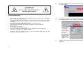
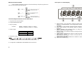
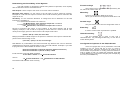
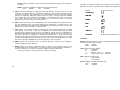
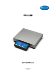
1
FABRICANTES DE BASCULAS TORREY S.A DE C.V.
TECHNICAL FEATURES
POWER SUPLIER
127 Vac/ 9Vdc
OPERATION TEMPERATURE
-10°C A 40°C
STORAGE TEMPATURE
-20°C A 50°C
INDICATOR SENSIBILITY
1.0 µV / GRADUATE
EXCITATION VOLTAGE
CURRENT
5 ± 0.02 Vcc, 8 X 350-Ohms or 16 X 700-Ohms
120 mA MAXIMUM (8 X 350 Ohms LOAD CELLS)
RATE OF SAMPLES
RESOLUTION
7 SAMPLES/SECOND
INT.: 1,000,000
EXT.: 10,000 (LEGAL FOR TRADE) 40,000 MAX
VISIBLE AREA, 48 X 160 mm
RS-232
DISPLAY
INTERFACE
R
PROGRAMMABLE WEIGHT INDICATOR
PIQ SERIES
NOTE: THE PIQ INDICATOR SERIAL NUMBER CAN BE FOUND IN THE BACK OF PIQ
INDICATOR. WE SUGGEST THAT YOU WRITE IT AT THE FOLLOWING BLANKS AND
KEEP THEM AS PERMANENT PROOF OF YOUR ADQUISITION, TO HELP IN THE
IDENTIFICATION IN CASE OF LOSS OR FURTHER COSULTATIONS.
DISTRIBUTOR:
User’s Manual
ADDRESS:
Release 1.1
PHONE:
PURCHASE’S DATE:
MODEL:
SERIAL NUMBER:
IMPORTANT: Before operate your Indicator, read this manual completely.
32
Possible Failures and Solutions
Index
Description
Introduction
Important Warnings
General Features of the PIQ Indicator
Name and Location of Important Parts
Description of the Display
Description of the Keyboard
PIQ Indicator Functions
Configuration Options of the PIQ Indicator
Menu’s Map
Installation
PIQ Indicator Calibration
Determining the sensibility of the system
Conversions
Special Applications
RS232 Serial Communication
Possible Failures and Solutions
Technical Features
2
Page
3
4
5
6
7
8
9
11
12
16
19
22
23
24
26
31
32
Before call to obtain technical support from your Authorized Distributor about any
problem or a question of your PIQ Indicator, we suggest first read this manual completely
again, to discard any possible wrong understanding of PIQ Indicator’s operation. Next it is
shown a list with the more frequently fails, that will be appeared join its possible solution. In
case it’s no found the solution for the problem of your PIQ indicator contact your Authorized
Distributor.
Problem
The PIQ Indicator
does not turn ON
Possible Cause
Solution
There is not power for Verify the power supplier is perfectly
operate
connected at the power contact and the
Indicator.
Verify with a Multimeter if there is
voltage at the power contact
Weight is not stable
Something
under
the Lift the platform or plate and remove
platform or plate
something if it is founded
Motion Indicator
There are vibration or airs Move the platform to other place
standstill on
flows
PIQ Indicator is not
Verify the cable is connected correctly
• Bad connection
showing the weight
• A different serial port with PC at the correct serial port
at the PC
defined.
• Software is incorrectly Configure the software accord the PIQ
Indicator manual.
configured
• The computer serial
port is wrong.
PIQ Indicator does
• A different Baud Rate Configure the printer accord the baud
not print the weight at • Bad connection
rate and specifications of the PIQ
the serial printer
• The port of the serial Indicator port.
printer is wrong.
Verify the cable is connected correctly
with printer.
PIQ Indicator shows • Weight on the scale Remove the weight over the platform
“HELP” message
over 50% of scale’s and turn On the Indicator again.
capacity.
• Cell damaged by hits. Replace damaged cells.
• Bad connection with Verify the connectors and cables of the
cell.
cells.
31
Introduction
8)
Close this window to see the weight on the scale.
9)
Normal Mode
The PIQ Indicator is a weigh device designed with the newest technology and keep
in mind the necessities required for industrial sector. Absolutely configurable for capacities
from 10 kilograms until 500 metrics tons, with 40,000 external divisions as maximum
(10,000 accord Handbook 44). Each one capacity has six possible resolutions. AutomaticZero Tracking and digital Filter programmable. Configurable serial communication to 2400,
4800 and 9600 bps. Tare by Keyboard and 49 programmable tares, eight for direct
accesses. Handle of two independent platforms.
The possibility to configure all its parameters at different forms and easy operation
become PIQ Indicator a very versatile instrument that it can be used in receipt scales,
platforms scales, bulk-truck scales, hopper scales, livestock scales. As company we thank
to you the confidence deposited in us by acquired one of our products and we are sure you
won’t be repented. Thanks.
10)
Tare Mode
11)
In case the weight is not showed in the computer screen. Verify the
following
- Serial cable is correctly connected.
- BAUD RATE for transmission is correctly configured.
- Serial port is not damaged.
- Verify the serial port is not using for other application.
30
3
5)
At from Hard Drive, execute the program “Scale.exe”, this action will open
the next window.
6)
At SCALE menu enter into CONFIGURATION option, by make a click with
the mouse left button. The window of Configuration will be opened.
7)
Configure the parameters to accord with the parameters of the PIQ
Indicator.
¡Caution!
Do not open the PIQ Indicator
Risk of short circuit
Important Warnings
Do not open the PIQ Indicator. Your warranty will be canceled. Only Authorized
personal can open the PIQ Indicator.
Verify periodically the good conditions of the sockets and connectors, cells, power
supplier and serial cable communications. Avoid the scale is free of powder, dampness
or oxidize.
Never wash the scale using a flow of water.
Do not use solvents or detergents for cleaning, just use a damp rag.
Never press the Keyboard with objects such as pencils, pens, knives, etc.
Do not drop it.
Do not expose it to the sun.
Connect the cells to physical ground.
Do not use a different power supplier than it is supplied with your PIQ Indicator
(127 Vac +/- 10% input 9 Vcc, 500 mA output).
-
-
Remember the good operation and time of your PIQ Indicator depends on the good
handle and correctly maintenance.
4
29
Unit Section: shows the unit that is configured in the PIQ Indicator.
Status Section: in this section can appear a “Z” letter means PIQ Indicator marks a center
of Zero, or a “M” letter means that weight is not stable.
General Features of the PIQ Indicator
At the end a carrier return will be sent (CR).
-
Additional Texts
Demo Software of the serial communication with the PC
At order to show you the serial communication of the PIQ Indicator with a PC, we
have development software that you can use to see the weight sent for the PIQ Indicator.
PROGRAM NAME:
REQUIREMENTS:
SCALE.EXE
80486X Or HIGHEST PROCESSOR
OPERATIVE SYSTEM WINDOWS95 or HIGHEST.
MOUSE
Installation Guide of the Software “Scale.exe”
1)
2)
Connect the PIQ Indicator to serial port of the PC using RS232 serial cable
(not included).
Turn On your PIQ Indicator.
3)
Turn On your computer
4)
Copy all the files into the 3 ½” disk included with the PIQ Indicator to the
hard drive of the computer.
28
-
-
Compact and light cabinet, easy to handling.
Its design permits to place it on a worktable or mounted in a wall.
Mechanism of movement frees and supports anti-skid to best position and
visualization.
Programmable capacities from 10 kg to 500 metrics tons.
6 possible division for each capacity.
Until 10,000 external divisions.
7 different levels for Zero Tracking.
20 different levels for digital Filter.
Acummulable Tare.
Tare by Keyboard easy to use.
49 memories for tares, 8 for direct access.
Three programmable keys for functions.
Conversions from kg to lb and metrics tons to short tons.
Programmable Initial Zero System Mechanics
Able to lock the Keyboard and ZERO, TARE, KEYBOARD TARE, M, R,
PRINT, T1-T8 and F1 – F3 keys.
RS232 Interface to communicate with a PC or serial printer.
Programmable Baud Rate (2400, 4800 o 9600 bps).
Net weight, gross weight and tare weight can be printed.
Keyboard with 39 keys.
Audible Keyboard.
Seal of Calibration by padlock.
LCD Display easy to read with Backlight.
Power supplier 127 Vac/9 Vcc.
Simple installation of cells.
Dual Analog-to-Digital converts.
5
Name and Location of Important Parts
Note: Shield is not connected.
N/C = No connection.
Format of the data sent to the PC
Usually, through the serial port, the data following are sent:
1)
2)
3)
4)
5)
6)
7)
8)
9)
10)
Stainless steel cabinet.
LCD Display.
Membrane Keyboard.
Support for worktable.
Cell’s connectors cover.
Cable protectors.
Security seal.
DB9 male connector for RS232 serial communication
Jack for the power supplier.
Support to wall.
Text Section: The message into this section depends on you are working in Tare mode. If
you are working in Tare mode the first three messages will be sent at different lines.
Although the forth message will be sent.
Weight Section: in this section the weight value will be sent. The Position dot depends on
the configured capacity in the PIQ Indicator. The first space is for the negative sign and it is
sending just in Tare mode.
6
27
RS-232 Communication
Description of the Display
The information following is useful for users that develop computer programs and
want to communicate with PIQ Indicator.
Technical Specifications of the Serial Port
1.- Asynchronous communication.
2.- Programmable Baud Rate.
3.- Sign of polarity.
RS-232:
MARK: 1 LOGICO (-3VDC A -12 VDC).
SPACE: 0 LOGICO (+3VDC A +12 VDC).
4.- Word Length:
START BIT
DATA BITS
PARID BIT
STOP BIT
1 BIT
8 BITS
0 BITS
1 BIT
5.- Sequence of bits:
MARK
SPACE
Bit inicial
Start
Bit
b0
b1
b2
b3
b4
b5
b6
b7 StopBit
final
1) Weight section. In the operation mode this section shows the NET WEIGHT, GROSS
WEIGHT or TARE WEIGHT. In the configuration mode this section can shows different
messages.
2) Unit section. In the operation mode this section shows the unit used to weigh (kg, lb, t).
3) Motion Filter indicator. This indicator stands on always the weight is not stable for a
short time.
4) GROSS indicator. This indicator stands on always that the weight showed in the
display represents the gross weight.
5) ZERO indicator. This indicator stands on always that the weight showed in the display
is equal to Zero.
6) TARE indicator. This indicator stands on always that the weight showed in the display
represents Tare weight.
7) NET indicator. This indicator stands on always that the weight showed in the display
represents the Net weight.
8) Center of Zero indicators. Indicates the condition of “Zero-Balance” in ±½ division.
9) Shorts tons indicator (ton).
Bit
6.- Configuration of DB9/DB25 and DB9/DB9 serial connectors:
26
7
Description of the Keyboard
MTN_I: Motion Indicator enabled.
Filt: Digital Filter enabled.
SAMP: readings to average with a value from 2 to 5.
D_ERR: error divisions with a value from 1 to 2.
Z_BLK: ZERO key enabled. Allow you move Zero reference while is weighing.
T_BLK: TARE key enabled. Allow you tare the weight over the scale.
IZSM: INITIAL ZERO SYSTEM MECHANIS enabled. Always you turn On the PIQ
indicator the weight over the scale is taking as initial Zero (until 20%).
PRNET: Enabled. Print NET weight.
PRGRS: Enabled. Print GROSS weight.
PRTAR: Enabled. Print TARE weight.
Live-stocks
8
Turn On the PIQ Indicator
Turn On/Off Backlight
Set Zero Reference
Sets current weight like Tare
Accept a TARE by Keyboard
Saves a Tare in a memory
Recall a Tare from a memory
Recall a TARE directly
Switch NET, TARE and GROSS weight
Sends the current weight to serial
Port
Allow input a numeric data
Do an assigned function
Accept a numeric data
Lock/Unlock Keyboard
Enters into the configuration menu
Allow move into the menu
AZT: Automatic-Zero Tracking define with two divisions (2 d).
MTN_I: Motion indicator disabled.
Filt: Enabled.
SAMP: samples to average with a value from 15 to 20.
D_ERR: error divisions with a value from 10 to 15.
Z_BLK: ZERO key enabled. Allow you move Zero reference while is weighing.
T_BLK: TARE key enabled. Allow you tare the weight over the scale.
IZSM: INITIAL ZERO SYSTEM MECHANIS activated. Always you turn on the PIQ
indicator the weight over the scale is taking as initial Zero.
PRNET: Enabled. Print NET weight.
PRGRS: Enabled. Print GROSS weight.
PRTAR: Enabled. Print TARE weight.
Note: All the others parameters can be define with theirs predefined values.
25
Specials Applications
All the parameters of the PIQ indicator can be configured in different combinations
to obtain the indicator is functioning in different forms. Below there is some recommended
combination for some special applications.
PIQ Indicator Functions
ON key
Turn On the PIQ Indicator.
Received Platforms
AZT: Auto-Zero Tracking defined with half division (0.5 d).
MTN_I: Motion Indicator Enabled.
Filt: Enabled.
SAMP: reading to average with a value from 2 to 5.
D_ERR: error division with a value from 1 to 2.
Z_BLK: ZERO key enabled. Allow you move the Zero reference while is weighing.
T_BLK: TARE key enabled. Allow you tare the weight over the scale.
IZSM: INITIAL ZERO SYSTEM MECHANIS activate. Always you turn on the PIQ
indicator the weight over the scale is taken as initial Zero.
PRNET: Enabled. Print NET weight.
PRGRS: Enabled. Print GROSS weight.
PRTAR: Enabled. Print TARE weight.
Hoppers
AZT: Auto-Zero Tracking disabled defined (0 d).
MTN_I: Motion Indicator disabled.
Filt: Digital Filter disabled, update the weight soon on the display.
Z_BLK: ZERO key disabled. Prevents you move Zero reference while is weighing.
T_BLK: TARE key disabled. Prevents you tare the weight over the scale.
IZSM: INITIAL ZERO SYSTEM MECHANIS disabled. Prevents the PIQ indicator
taking the weight over the scale as initial Zero when you turn on the indicator.
Bulk-Truck Scale
AZT: Auto-Zero Tracking defined with 1.5 division (1.5 d).
MTN_I: Motion Indicator Enabled.
Filt: Enabled.
24
Backlight key
Turn ON/OFF the Backlight.
ZERO key
Set the Zero reference.
TARE key
When this key is pressed the weight over the scale is taken it like the TARE weight,
as such contents, recipients, packaged or others things; this weight is not included to
determinate the NET weight indicator. In this moment the display shows Zero and the net
indicator stands on. If all the weight on the scale is taken away the display shows negative
weight equal to the TARE weight. To exit from TARE mode take away all the weight on the
scale and press TARE key again. The maximum tare is equivalent to the maximum
capacity of the scale minus an external division.
Keyboard TARE key
Set a numeric input like TARE weight. The manual tares should be in the same
units and minimum division of the PIQ Indicator. Pressed the KEYBOARD TARE key
following the value data and then press ENTER key to accept this value. If you want to
recall the last tare by keyboard, press the next sequence of keys R,0,0.
Save TARE key
The PIQ Indicator has 49 programmable tares by cell from 01- to 49. Using the
numeric Keyboard type the value of tare that you wish to save, following press M key and
then type the memory number with two digits to recall the tare weight. At end the display
shows SAVED message that indicates the TARE weight has been saved in memory.
9
Recall Tare Key
To recall a programmed tare press R key and then type the memory number with
two digits (01-49) of the tare to recall.
Saving Tares by Direct Access
The PIQ Indicator has eight direct accesses that correspond with the eight
first memories programmable tares. These memories can be saved or recalled press the
T1 – T8 keys. Using the numeric Keyboard type the tare value that you wish to save,
following press M key and then press the direct access key to recall this TARE weight. At
end the display shows the SAVED message to indicate that TARE weight has been saved
in memory.
Recall Tares by Direct Access
Press the direct access key (T1 - T8) has the TARE weight to recall. Automatically
the display shows the different between GROSS weight and the TARE weight that has
been recalled.
NET weight, TARE weight and GROSS weight
If someone of the methods has set a value of TARE weight, and you wish to altern
the weight showed in the display, press GROSS-TARE-NET key. When the GROSS
indicator is enabled the weight showed in the display represent the GROSS weight, it’s so
the real weight on the platform or plate of the scale. When the TARE indicator is enabled
the weight showed in the display represent the TARE weight. When the NET indicator is
enabled the weight showed in the display represent the NET weight. That so it’s the
GROSS weight minus TARE weight.
Print key
Press this key to send the current weight on the scale through the RS-232 serial
port.
Numeric Keyboard
Using these keys to enter a numeric input data in the normal mode or the
configuration mode.
10
In the case when the real graduation is lower than the specified graduation of the
indicator, the system is not working correctly. To be able to increment the real sign you
should modify someone of the next variables.
a)
b)
c)
Use a load cell with more rate output.
Use a load cell nearest to the capacity of the scale it’s so to increment the percent
of rate output of the load cell.
Increment the minimum external division to decrement the counts of internals
graduations.
Factors of Conversion
They are supplied with the intention of the user has an exactly reference of the
equivalent units.
a) Conversion formula from kg to lb
1 kg = 2.20458 lb
Example: 10 kg = ? lb
Then:
1 kg = 2.20458 lb
10 kg = 2.20458(10)
10 kg = 22.0458 lb
b) Conversion formula from lb to kg
1 lb = 0.4536 kg
Example: 100 lb = ? kg
Then:
1 lb = 0.4536 kg
100 lb = 0.4536(100)
100 lb = 45.36 kg
c) Conversion formula from t to ton
1 t = 1.10229 ton
Example: 30 t = ? ton
Then:
1 t = 1.10229 ton
30t = 1.10229 (30)
30t = 33.0687 ton
d) Conversion formula from ton a t
1 ton = 0.9072 t
Example: 33.0687 ton = ? t
Then:
1 t = 0.9072 ton
1 t = 0.9072 (33.0687)
1 t = 30
23
Determining the Sensibility of the System
Functions keys
The PIQ Indicator is designed to handle many different capacities, each capacity
with six different minimum external divisions.
Rate Output: It is the output of the cell in mV for each Volt of excitation.
Maximum Rate Output: It is the output of the cell when it has its maximum capacity;
Example for a cell with rate output of 3.0mV/V and 5 Volts excitation gives a maximum rate
output of 15 mV.
Sensibility: It is the minimum difference of voltage that can be detected. For the PIQ
Indicator the sensibility is:
For 10,000 external divisions as maximum:
1.0 µV/Graduates; with maximum output rate >= 10 mV
For 40,000 external divisions as maximum:
0.25 µV/Graduates; with maximum output rate >= 10 mV
Percent of maximum rate output: it is the relation of the useful capacity and its total
capacity. Example, a cell of 500 lb of capacity it will be used for a scale of 400 lb. This
mean just the eighty percent of the maximum rate output will be used.
(400 lb / 500 lb) = 0.80, this mean 80%
Multiply the Maximum Rate Output for the percent of maximum rate output to calculate the
percent of the electrical sign to use.
The Function keys are used to call a previously defined function that can be turn
off, switch cell, switch units, etc.
Menu key
Enters to Configuration Mode of the scale.
When you are into the Configuration Mode return a level.
Arrows keys
They are used to move into the configuration menu and locate a specific option.
Enter key
It used to confirm when a parameter is updated.
Unlock/Lock key
Join the ENTER key is used to lock and unlock the Keyboard. Press
UNLOCK/LOCK key following ENTER key, to lock the Keyboard, repeat this action to
unlock the Keyboard.
(15 mV/V) * (0.80) = 12 mV, of useful sign.
Real Relation of µV/Graduation: the useful electrical sign divide at the count of electronic
graduates that it has been programmable to use in the PIQ Indicator. Example: if you want
to programmer the PIQ Indicator for 400 lb x 0.05 lb.
Electronic Graduates = (Nominal Capacity / Minimum Division)
Electronic Graduates = (400 lb / 0.05 lb) = 8000
If PIQ Indicator works with 8000 graduates,
12 mV/ 8000 = 0.0015 = 1.5 µV/ Real Graduation
Configuration Options of the PIQ Indicator
At the next pages each one of parameters of the PIQ Indicator are described. If the
Indicator is turn off, press ON key to turn on. Press MENU key to enter into the
configuration menu. Using the Arrow keys to position on the option to modify. When you
has localized the parameter to modify press the ENTER key or RIGHT ARROW key to
enter to update it. After you update the parameter press ENTER key to save the changes
or press MENU key to cancel the changes (see example page 13). To return one level from
the menu press MENU key.
That so
1.5 µV/ Real Graduation > 1.0 µV/Graduation of PIQ Indicator.
Forward the PIQ Indicator works correctly.
22
11
j)
Press ENTER key to define this parameter. Using the arrow keys selecting the external
division to use in the scale. Press the ENTER key to accept this value or press the
MENU key to cancel and return one level menu.
k) %LD: Define the calibration percent in relation of the nominal capacity of the scale.
Depending on the nominal capacity could not be possible to have the load of calibration
equivalent to the nominal capacity. In this case you can use a percent of load.
Example: is a scale of the nominal capacity of 100 kg, but you only have 50 kg of test
weights, you should define the percent of calibration with a value of 50%. Press the
ENTER key to define this parameter. Use the numeric Keyboard to define the capacity
of the scale. Press the ENTER key to accept this value or press the MENU key to
cancel and return one level menu. If a zero is defined in this parameter when the scale
will calibrate asks for the load of calibration. If you want to calibrate with a specific net
weigh, define this parameter to zero. At the moment to take the calibration reference
(RZERO) will request you this weigh.
k) RZERO: Take the scale reference when it is without weight on the platform or structure.
Press the ENTER key to modify this parameter. The display will show “NOW?”
message asking for the confirmation to the value reference *. Press the ENTER key to
confirm this action or press the MENU key to cancel and return one level menu. The
digital filter must be disable for best performance.
l)
LOAD: Take the scale reference when it is with the load of calibration on the platform
or structure. Press the ENTER key to define this parameter. The display will show
“NOW?” message asking for the confirmation to take the reference value *. Press the
ENTER key to confirm this action or press the MENU key to cancel and return one level
menu.
m) IZSM: Enable the Initial Zero System Mechanism always the scale is turn ON or when
the cells are switched. This parameter must be disable for those system where the
method or charge makes impossible to take away the weight on the platform or
structure for get other Initial Zero. This parameters should be disable for all the systems
where the method or charge the scale become impossible to take away the weight on
the platform or structure to take another Initial Zero when the PIQ Indicator is turn OFF
accidentally. (Hoppers, Tanks, railroad). Press the ENTER key to define this
parameter. Select “YES” if you want to enable this option or select “NO” if you don’t
want this option. Press the ENTER key to accept this value or press the MENU key to
cancel and return one level menu.
n) Press the MENU key to exit from configuration menu and begin to use the scale
o) Put the calibration seal over the DIP SWITCH again.
* When the reference of the scale is reading, neither value is took as stable, at less the
same value is gotten 10 times consequently. In the case it is not possible to get a
stable value, it will be possible to take the last read as stable by press the ENTER key.
12
21
LOAD: Take the reference of the scale with the Calibration weigh over the plate or
structure.
Example, is required to modify the configured unit of weight from kilograms (kg) to pounds
(lb) when you are in operation mode. Realize the following sequence of keys.
IZSM: Enable or disable the Initial Zero System Mechanism.
YES
- Enable
NO
- Disable
Display
a) CELL: The first parameter to configure of the PIQ Indicator it is the cell to use. In the
case that your PIQ Indicator is not able to handle two cells, leave this option with the
number 1 as value. If your Indicator is able to handle two cells you must define which
cell will be calibrated. While the display show the “CELL” message press the ENTER
key to define the cell to calibrate. Use number “1” to define the one cell or use number
“2” to define the two cell. Press the ENTER key to accept this value or press the
MENU key to cancel and return one level menu.
0.000 kg
b) UNIT: Define the weigh unit to calibrate the scale. Press ENTER key to define the unit,
use the ARROWS keys to select lb (pounds), kg (kilograms), T (metrics tons) o ton
(short tons) like unit of weight. Press the ENTER key to accept this value or press the
MENU key to cancel and return one level menu.
KG
c) CAP: Define the nominal capacity to calibrate the scale. Press ENTER key to define
the capacity of the scale. If the unit of calibration is defined like pounds the valid
options for the capacity will be from 20 to 100,000 lb. When the unit of calibrations is
defined like kilograms the valid options for the capacity will be from 10 to 100,000 kg. In
the case of the unit of calibration is defined like metrics tons or short tons the valid
options for the capacity will be from 10 to 500 and from 20 to 500 respectively. Use the
numeric Keyboard to define the capacity of the scale. Press the ENTER key to accept
this value or press the MENU key to cancel and return one level menu.
CELL#
d) NMAX: Define the maximum count of external divisions, These can be defined in
10000 or 40000 external divisions.
l)
DIVM: Define the minimum external division to show on the display, there are six
possible divisions for each capacity. The minimum division always will be multiples of 1,
2 and 5. Example: for a scale of 10 kg the possible minimum division are:
‘0.001 kg, 0.002 kg, 0.005 kg, 0.010 kg, 0.020 kg, 0.050 kg
Sequence of keys
EN/SP
UNIT
Lb
0.00 lb
Ready the PIQ Indicator is configured in pounds(lb).
OPTIONS
EN/SP: Select the idiom to use on the display and that weight that will be printed through
the RS232 serial communication.
ENG - English
SPN - Spanish
UNIT: Select the unit of weight.
kg
- kilograms
lb
- pounds
t
- Metrics Tons ( 1 t = 1000 kg)
ton
- Short Tons (1 ton = 0.9072 t)
CELL: Select the cell to use.
1
- cell number 1
2
- cell number 2
Z BLK: disable or enable the ZERO key.
YES
- disabled
NO
- enabled
20
13
AZT: Set the range of the AUTOMATIC ZERO TRACKING. AZT is the range around the
CENTER OF ZERO where all the samples are taken like the new CENTER OF ZERO; it so
to order to eliminate any variation from the Initial Zero by residuals of material lay on the
plate or platform.
0d
- disabled
0.5 d - half minimum external division
1d
- one minimum external division
1.5 d - one and half minimum external division
2d
- two minimum external division
3d
- three minimum external division
4d
- four minimum external division
MNTI: Enable or disable the Motion Indicator. The Motion Indicator stands turns on while
the weight is not stable for one-second o more.
YES
- enabled
NO
- disabled
FILT: Configure the digital Filter. The filter average several samples to order to eliminate
any variation of the weight by vibration, rain, air flows, etc.
ENAB: Enable or disable the digital Filter.
YES
- enabled
NO
- disabled
SAMP: Sample number to average. The Filter value can be from 2 to 20. The rate
of reads of the PIQ Indicator is approximately 7 samples x second.
D_ERR: The number of error division between one sample and the last. The value
of error division can be from 1 to 20.
TARES: Enters sub menu of tares.
T BLK: Disable or enable TARE key.
YES
- disabled
NO
- enabled
KTBLK: Disable or enable KEYBOARD TARE key.
YES
- disabled
NO
- enabled
M BLK: Disable or enable “M” and “R” keys.
YES
- disabled
NO
- enabled
Guide of Calibration
Before to enter into the Calibration menu, you should verify that is not any weight
on the platform or structure, and that cells are connected at connector board of the PIQ
Indicator in according to the specified by this manual (page 16).
PIQ Indicator Calibration
(To realize only for an installer who must be an Authorized Technical in Instruments of
Weights and Measures)
In the back of PIQ Indicator is located the calibration seal. Remove it.
e) Under the seal it is found the DIP SWITCH to the calibration access. Put these
switches to ON.
Dip
Calibration
Seal
Switch
“ON”
f) If the PIQ Indicator is turn off, press the ON key to turn on.
g) When the counter is finish, press the MENU key to enter into the Configuration menu.
h) Using the arrows keys position you the sub menu CALIB (see Menu’s map page. 12).
Calibration Menu
CALIB: Enters into Calibration menu.
CELL: Select the cell to use.
1 - Cell number 1
2 - Cell number 2
UNIT: Define the unit of weight to calibrate.
kg
- kilograms
lb
- pounds
t
- Metric Tons ( 1 t = 1000 kg)
ton
- Short Tons (1 ton = 0.9072 t)
CAP:
Define the Nominal Capacity PIQ Indicator.
NMAX: Select the maximum amount of external divisions.
10000 - 10000 external divisions
40000 - 40000 external divisions
DIVM: Define the minimum division to use
%LD: Set the capacity percent for the calibration.
If you want to calibrate with a specific net weigh, define this parameter to zero. At
the moment to take the calibration reference (RZERO) will request you this weigh.
RZERO: Take the Zero reference of the scale (initial death load), The weight of the
plate or structure.
14
19
PRINT: Enters to the Print sub menu.
BAUDR: Set the value of baud rate for the RS232 serial communication.
2400 - 2400 bits per second
4800 - 4800 bits per second
9600 - 9600 bits per second
PRBLK: Disable or enable the PRINT key.
YES
- disable
NO
- enable
PIQ Indicator Installation with a Cell and a Platform
PRNET: Enable or disable to print NET weight.
YES
- enable
NO
- disable
PRGRS: Enable or disable to print GROSS weight.
YES
- enable
NO
- disable
PRTAR: Enable or disable to print TARE weight.
YES
- enable
NO
- disable
CCTRL: Select the control character to end the lines.
CR
- Carrier return
LF
- Line Feed
CR FF - Carrier return Form Feed (label mode)
LF FF - Line Feed
Form Feed (label mode)
CALIB: Enters into sub menu of Calibration (see Calibration of PIQ Indicator page19).
FUNC: Enters into sub menu of Function Keys. Into this sub menu you can defined a
function for each function key (F1 – F3). The possible options for these keys are the next.
NONE: None function.
OFF: Turn off the Indicator.
CELL: Select the cell.
UNITS: Select weight unit.
MOTIO: Enable or disable the MOTION INDICATOR.
TRACK: Enable or disable the Autotracking-Zero Tracking.
FILT: Enable or disable the DIGITAL FILTER.
TARE: Assign a programmable tare to the key.
EXIT: Exit from Configuration menu.
Note: The calibration options only are accessible if the DIP SWITCH of the calibration
access is.
18
15
Installation
Unpack the PIQ Indicator and check is in good conditions, in case there is a defect
report it immediately with your Authorized Distributor.
To connect the load cell to the PIQ Indicator, take away the connectors cover that
is in the back of the indicator. Pass the cable through the cable protector as shows
the next figure.
Cell Installation
View of the connection of a load cell
LOADCELL
CONECT OR
LOADCELL
Load cell color code (Torrey)
Option 1
Red
Black
nc
nc
nc
Green
White
Option 2
Green
Black
Brown
Shield
Blue
Red
White
(Shield)
Configuration of the connector
After makes the connections put the connector cover at its place. Connect the
power supplier to a contact of 127Vac and put the plug of the power supplier into
the jack at the back of the PIQ Indicator.
16
Platform Installation with four cells by summing junction board.
17