1
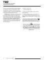
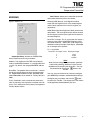
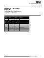
June 2004
225-720-02B
TMZ
PC-Programmable MODBUS
Temperature Transmitter
TMZ
PC-Programmable MODBUS
Temperature Transmitter
TPRG
Left: TMZ TPRG: PC-Programmable MODBUS Temperature Transmitter
Right: TMZ HLPRG: PC-Programmable MODBUS Signal Converter
All product names are registered trademarks of their respective companies.
Table of Contents
Introduction .................................................................................................... 4
About this Manual ........................................................................................................... 4
The TMZ ......................................................................................................................... 4
Model and Serial Numbers ............................................................................................. 4
Specifications ................................................................................................ 5
Dimensions ..................................................................................................................... 7
Configuring the TMZ ...................................................................................... 8
Installing the Configuration Software .............................................................................. 9
Connecting the TMZ to the PC ........................................................................................ 9
PC Configuration Software Summary ...................................................... 10
Status and Tool Bar Legend ......................................................................................... 11
Configuration Screens ............................................................................... 12
Input .............................................................................................................................. 12
Trimming ....................................................................................................................... 13
Scaling & Custom Curve ............................................................................................... 13
MODBUS ...................................................................................................................... 15
Installation ................................................................................................... 16
Mounting the TMZ ......................................................................................................... 16
Making the Electrical Connections ................................................................................ 16
Recommended Ground Wiring Practices ...................................................................... 16
CE Conformity............................................................................................................... 16
Operation ..................................................................................................... 16
Maintenance ................................................................................................................. 16
Customer Support ...................................................................................... 16
Appendix A: TMZ MODBUS Register Set ................................................ 17
TMZ
PC-Programmable MODBUS
Temperature Transmitter
The TMZ
Introduction
This is the users’ manual for the Moore Industries
TMZ PC-Programmable MODBUS Temperature
Transmitter (TPRG: RTD, T/C, Ohms, mV and
Potentiometer inputs). It contains all of the
information needed to configure, install, operate and
maintain this instrument.
About this Manual
Wherever you see a “Note”, “Caution” or “WARNING ”
pay particular attention.
WARNING - Hazardous procedure or condition that
could injure the operator.
Caution - Hazardous procedure or condition that could
damage or destroy the unit.
Note - Information that is helpful for a procedure,
condition or operation of the unit.
The TMZ is a PC-Programmable, user-configurable,
signal converter. It has a digital output and retains the
high accuracy of an Analog to Digital converter without
the limitation of low resolution which is associated with
analog outputs. The multi-drop nature of the RS-485
port allows the connection of up to 32 units on a single
drop of cable that consists of two pairs of wires. The
TMZ has a READY LED to indicate the health of the
unit and an INPUT LED to indicate status.
Model and Serial Numbers
Moore Industries uses the model and serial numbers of
our instruments to track all information on each unit
that we sell and service. If a problem occurs with your
TMZ, check for a tag affixed to the unit listing these
numbers. Supply the Customer Support representative
with this information when calling.
Inputs
Refer to Table 4 for input ranges and accuracies of the
TMZ (TPRG).
Figure 1. The TMZ (TPRG)
1
2
3
4
Outputs
READY
INPUT
RS-232 Port
MODBUS Terminals
A
B
S
4
The Interface Solution Experts
TMZ
PROGAMMABLE
MODBUS
TRANSMITTER
COM
The TMZ has a standard RS-485 port that supports the
MODBUS RTU protocol.
TMZ
PC-Programmable MODBUS
Temperature Transmitter
Specifications
Performance
Input Accuracy:
See Table 4
Overall Accuracy: The
overall accuracy of the
unit is the input accuracy.
It includes the combined
effects of linearity,
hysteresis, repeatability
and adjustment resolution.
It does not include ambient
temperature effect. For
T/C input, add the RJC
error.
Cold Junction
Compensation Accuracy
(T/C Inputs Only):
±0.45°C
Stability: See Table 1
Response Time: INPUT
UPDATE TIME: 128msec;
MODBUS POLLING TIME:
Dependent upon how fast
and how often a MODBUS
master requests data
Isolation: Standard unit,
1000Vrms between case,
input. 1500Vrms between
power and input; WITH
-RF OPTION, 500Vrms
between case, input and
power.
Power Consumption:
1W max.
Input Impedance:
T/C and mV inputs,
40Mohms, nominal
Performance
(continued)
Input Over-Range
Protection: ±5Vdc
Excitation Current
(RTD and Ohm Inputs
Only): 250µA, ±10%
Communications
Type: Standard
MODBUS RTU protocol
interface over RS-485
(parameters as specified
in U.S. Standard EIARS485)
Address Range:
Configurable from 1 to
247. Unit will assume a
MODBUS address of 01
by default.
Baud Rates: Interface
supports the following:
300, 600, 1200, 2400,
4800, 9600, 19.2k and
38.4k
Character Format: One
start bit, 8 data bits and
one stop bit
Indicators
LED Type: INPUT LED:
Dual color LED indicates
input failure
READY LED: Green
LED indicates unit is
operating properly
Ambient
Conditions
Weight
Operating & Storage
Range: -40°C to +85°C
(-40°F to +185°F)
Effect of Ambient
Temperature on Cold
Junction
Compensation (T/C
Inputs Only):
±0.005°C per °C change
of ambient temperature
Relative Humidity:
0-95%, non-condensing
Ambient Temperature
Effect: See Table 3
RFI/EMI Immunity
(Standard Unit):
10V/m@20-1000MHz,
1kHz when tested
according to
IEC1000-4-3-1995
WITH -RF OPTION,
30V/m@20-1000MHz,
1kHz AM when tested
according to
IEC1000-4-3-1995
Noise Rejection:
Common mode,
100dB@50/60Hz;
Normal mode, Refer to
Table 2
290 g (10.2 oz)
Specifications and information subject to change without notice.
Table 1. Long-Term Stability
Stability
(% of maximum
span)
RTD, Ohm & Pot Inputs
T/C & mV Inputs
Table 3.
Ambient Temperature Effect
Input-to-Output
(Years)
Input Type
*RTD
0.0035°C
1
3
5
Millivolt
0.5µV + 0.005% of reading
0.09
0.16
0.21
Ohm
0.002ohms + 0.005% of reading
0.08
0.14
0.18
Accuracy per 1°C (1.8°F) change in Ambient
Thermocouples
Input Type
Accuracy per 1°C (1.8°F) change in Ambient
J
Table 2. Normal Mode Rejection Ratio
T/C: J, K, N, C, E
T/C: T, R, S, B
Pt RTD: 100, 200, 300ohms
Pt RTD: 400, 500, 1000ohms
Ni: 120ohms
Cu: 9.03ohms
Max. p-p Voltage Injection
for 100dB at 50/60Hz
150mV
80mV
250mV
1V
500mV
100mV
Resistance
mV
1-4kohms
250-1000
0.25-1kohms
62.5-250
0.125-0.25kohms 31.25-62.5
1V
250mV
100mV
Sensor Type
0.00016°C + 0.005% of reading
K
0.0002°C + 0.005% of reading
E
0.00026°C + 0.005% of reading
T
0.0001°C + 0.005% of reading
R, S
0.00075°C + 0.005% of reading
B
0.0038°C + 0.005% of reading
N
0.0003°C + 0.005% of reading
C
0.00043°C + 0.005% of reading
mV
0.5µV + 0.005% of reading
*Accuracy of Ni672 is 0.002°C
The Interface Solution Experts
5
TMZ
PC-Programmable MODBUS
Temperature Transmitter
Table 4. Accuracy with RTD, Thermocouple, Ohms, Potentiometer and Millivolt Inputs
Input
Type
α
RTD
(2-, 3-,
4-Wire)
Ohms
Conformance
Range
Input
Accuracy/Repeatability
Maximum
Range
100
200
300
0.003850
400
-200 to 850°C
(-328 to 1562°F)
-240 to 960°C
(-400 to 1760°F)
500
1000
Platinum
±0.1°C
(±0.18°F)
100
200
0.003902
-100 to 650°C
(-148 to 1202°F)
-150 to 720°C
(-238 to 1328°F)
-200 to 510°C
(-328 to 950°F)
-80 to 320°C
(-112 to 608°F)
-50 to 250°C
(-58 to 482°F)
±0.85°C
(±1.53°F)
-240 to 580°C
(-400 to 1076°F)
-100 to 360°C
(-148 to 680°F)
-65 to 280°C
(-85 to 536°F)
0-4000
0-4000ohms
±0.4ohms
0-4095ohms
4000 max.
0-100%
±0.1%
0-100%
400
500
1000
0.003916
100
Nickel
0.00672
120
Copper
0.00427
9.035
Direct Resistance
Ohms
n/a
Potentiometer
T/C
mV
6
J
n/a
n/a
-180 to 760°C
(-292 to 1400°F)
±0.25°C
(±0.45°F)
-210 to 770°C
(-346 to 1418°F)
K
n/a
n/a
-150 to 1370°C
(-238 to 2498°F)
±0.30°C
(±0.54°F)
-270 to 1390°C
(-454 to 2534°F)
E
n/a
n/a
-170 to 1000°C
(-274 to 1832°F)
±0.20°C
(±0.36°F)
-270 to 1013°C
(-454 to 1855.4°F)
T
n/a
n/a
-170 to 400°C
(-274 to 752°F)
±0.25°C
(±0.45°F)
-270 to 407°C
(-454 to 764.6°F)
R
n/a
n/a
0 to 1760°C
(32 to 3200°F)
±0.55°C
(±0.99°F)
-50 to 1786°C
(-58 to 3246.8°F)
S
n/a
n/a
0 to 1760°C
(32 to 3200°F)
±0.55°C
(±0.99°F)
-50 to 1786°C
(-58 to 3246.8°F)
B
n/a
n/a
400 to 1820°C
(752 to 3308°F)
±0.75°C
(±1.35°F)
200 to 1836°C
(392 to 3336.8°F)
N
n/a
n/a
-130 to 1300°C
(-202 to 2372°F)
±0.40°C
(±0.72°F)
-270 to 1316°C
(-454 to 2400.8°F)
C
n/a
n/a
0 to 2300°C
(32 to 4172°F)
±0.80°C
(±1.44°F)
0 to 2338°C
(32 to 4240.4°F)
mV
n/a
n/a
n/a
±15µV
-50 to 1000mV
The Interface Solution Experts
TMZ
PC-Programmable MODBUS
Temperature Transmitter
Figure 2. TMZ (TPRG) Dimensions
138mm
(5.43 in)
WHEN INSTALLED
133mm
(5.24 in)
25mm
(1.00 in)
1
2
READY
INPUT
WHEN INSTALLED
126mm
(4.97 in)
3
4
TMZ
52mm
(2.05 in)
PROGAMMABLE
MODBUS
TRANSMITTER
100mm
(3.94 in)
C
L
COM
48mm
(1.89 in)
Table 5. Terminal Designations
Top Terminals (Left to Right)
Input Type
T1
T2
T3
T4
KEY:
RTD, Ohms, Potentiometer,
T/C & mV Inputs
See Figure 3
Bottom Terminals (Left to Right)
Row 1
Row 2
MODBUS Output
Power
B1
B2
B3
B4
A
B
S
Not Used
Not Used
Not Used
+
–
A = A MODBUS
B = B MODUBUS
S = S MODBUS
+ = Positive power input
– = Negative power input
NOTES:
1. Terminal blocks can accommodate 14-22 AWG solid wiring.
Figure 3. Temperature Sensor Hook-Up Guide
Thermocouple
and Millivolt
Input
+
2-Wire RTD
or Decade
Resistance Box
3-Wire RTD
or Decade
Resistance Box
4-Wire RTD
or Decade
Resistance Box
Potentiometer
Input
1 234
1 2 3 4
1 234
1 234
–
12 3 4
The Interface Solution Experts
7
TMZ
PC-Programmable MODBUS
Temperature Transmitter
Figure 4. Hooking-Up the TMZ (TPRG)
MILLIVOLT _
SOURCE
OR T/C +
SIMULATOR
MODBUS Host
TO SERIAL
(COM) PORT
OF PC
OHMS OR
2-WIRE
RTD
SIMULATOR
1
2
READY
INPUT
3
4
PC
TMZ
PROGAMMABLE
MODBUS
TRANSMITTER
COM
TO SERIAL
(COM) PORT
OF PC
RS-485/RS-232 A
B
Converter
S
MODBUS OUTPUT
24Vdc
POWER
+ SUPPLY
–
INPUT HOOKUP CONNECTIONS
4-Wire RTD or
Decade Resistance Input
3-Wire RTD or
Decade Resistance Input
OHMS
OR RTD
SIMULATOR
OHMS
OR RTD
SIMULATOR
Configuring the TMZ
One of the benefits of the TMZ is that there are no internal or external controls to adjust or settings to
change. All operating parameters are set using a PC
and Moore Industries’ Intelligent PC Configuration
Software.
8
The Interface Solution Experts
Potentiometer Input
The software settings are downloaded to the
transmitter in the form of a Configuration File and
stored in the instrument’s memory. You can save a
backup copy of the file on your PC hard drive or disk.
The transmitter communicates with the PC through an
RS-232 connection to the PC’s serial port or through
the MODBUS output with a fixed baud rate at 19.2k.
TMZ
PC-Programmable MODBUS
Temperature Transmitter
Installing the Configuration
Software
This makes it easy to create a set of operating parameters, save them to disk, and download them to one or
more transmitters at a later time.
Refer to Table 6 for the equipment needed.
1.
Insert the Moore Industries Interface Solution
PC Configuration Software CD into the CD drive
of the PC. Access the CD and open the “TMZ
PC Configuration Software” folder.
The TMZ must be connected to the PC in order to:
perform sensor trimming; assign a tag, descriptor or
message; receive (via download) a configuration file;
and save the configuration file from the transmitter’s
memory.
2.
Double-click the installation program located in
the folder. Follow the prompts to correctly
install the program.
Connecting the TMZ to the PC
Once the Configuration Program is installed on the PC,
the TMZ can be connected to equipment to simulate
input and monitor output. You can then change the
transmitter’s operating parameters.
Connect the RS-232 end of the cable to the PC’s COM
port.
See Table 6 for information on the necessary equipment.
No Transmitter Needed
It is not necessary to connect the transmitter to a PC
to create configuration files using the software. The
Configuration Program can be run without connecting a
transmitter, and most parameters can be set
without the benefit of input from a sensor or TMZ.
Table 6. Assembling the equipment needed to configure the TMZ (TPRG)
Device
Specifications
Variable Input Simulator for Thermocouple,
RTD, Millivolt, Potentiometer, or Decade Variable; Accurate to ±0.05% of unit span
Resistance Box
Power Supply 24Vdc, ±10%
80386-based(or faster) IBM PC, or 100% compatible;
1.44Mb floppy diskette drive
4Mb free RAM; 8Mb recommended; 20Mb free disk space on hard drive
(More RAM & hard disk space is required for Windows 98, NT 2000 or XP)
Personal Computer Microsoft Windows® 95, 98, NT, 2000 or XP
Internet Explorer 3.0+
1 (one) serial port (COM 1, 2, 3, or 4) set to 19.2k baud, no parity, 8 data bits,
and 1 stop bit
Moore Industries PC Version 1.0 or greater, successfully installed to the hard drive
Configuration Software
Communication Cable Part# 803-053-26
The Interface Solution Experts
9
TMZ
PC-Programmable MODBUS
Temperature Transmitter
PC Configuration Software Summary
Figure 5. TMZ (TPRG) PC Configuration Software Screen
1
10
6
2
11
12
13
3
7
4
5
8
9
Once the default configuration has been saved to disk,
it is safe to program other parameters. The PC
Software is made up of these sections:
1. Tool Bar/Status Bar– Dropdown menus and corresponding icons allow you to perform various functions
throughout the PC Configuration Program. Refer to the
Status and Tool Bar Legend section for a complete
description.
2. Program Status– This portion of the program displays the activity (idle, monitoring, downloading, uploading) of the connected unit.
3. Device ID– Displays your unit configuration
(HLPRG/TPRG), ID, Hardware revision and Software
revision.
10
The Interface Solution Experts
4. Identification Parameters– Use this parameter to
place an identifying “Tag” (8 alphanumeric characters
max.), “Descriptor” (16 alphanumeric characters max.)
or “Message” (32 alphanumeric characters max.). You
may also use the Quick Set feature to set your Tag
and download it. Simply click the
button in the
Tool Bar.
5. Device Configuration– Displays the Input and
MODBUS parameters you have chosen as settings for
your TMZ.
6. Input Type– Select your input type (RTD, T/C,
Ohms, mV and Potentiometer) and characteristics.
7. Variables– Displays the value of the Process Variable that is being monitored, the Reference Junction
temperature, the scaled output and the Custom Curve
output.
TMZ
PC-Programmable MODBUS
Temperature Transmitter
8. Device Status– Notifies of any errors or conditions
which are outside of tolerance range.
9. Communications– Indicates current PC connection/communications status.
10. Input– Use this tab to set your input parameters.
Refer to the Input section for a complete description.
11. Trimming– This parameter allows you to configure and perform sensor trimming. Refer to the
Trimming section for a complete description.
12. Scaling & Custom Curve– Use this portion of the
screen to set up your custom curve table. Refer to the
Scaling & Custom Curve section for a complete
description.
13. MODBUS– Allows you to configure your MODBUS
parameters. Refer to the MODBUS section for a
complete description.
Status and Tool Bar Legend
Allows such functions as New,
Open, Save and Print
Allows you to Upload and
Download configurations
Select the PC Port
(Comm Port) that you will use
Allows you to Monitor and
Stop monitoring processes
Provides functions specific to
your Custom Curve table
Controls whether Tool and Status
Bars are viewed on the screen
Displays the version of the TMZ
Configuration Program
Quick Set Buttons
The Interface Solution Experts
11
TMZ
PC-Programmable MODBUS
Temperature Transmitter
Configuration Screens
Input
Figure 6. Input Tab
Running Average Filter– This function is for filtering the input signal. The TMZ provides this filter with
a user-selected range between 1 and 16. Factory default is 4.
Note:
A higher Running Average Filter setting provides
smoother output transitions however, reduces
response time. Conversely, a lower setting provides
a faster response time, but may seem more
unstable.
Input Filter– This setting is used to configure the
input filter. This filter is designed to reduce the effects
of mains-induced noise. The input filter frequency
value should be set to the frequency of the local AC
supply-either 50Hz or 60Hz.
Note:
Once you have configured all parameters, download
to the unit by selecting “Download” in the Transfer
dropdown menu located in the Status Bar. You may
also download by clicking the
button in the
Tool Bar.
Input Range– Allows you to set your “Upper
Range Value” (URV) and “Lower Range Value” (LRV)
depending upon the input configuration and range chosen in the Input Type section.
Temperature Measurements– Select the unit in
which you wish your Input Range displayed. Choose
from Deg C, Deg F, Kelvin or Deg R.
Broken Wire– Allows the TMZ to continuously
test the integrity of your sensor wiring by sending out
random microamp pulses during operation. If a problem is detected, a message is displayed in the Device
Status box.
12
The Interface Solution Experts
You may also use the Quick Set feature to configure
your Input parameters and download the settings.
Configure your parameters and click the
button,
located in the Tool Bar. The input settings you have
chosen will be applied and downloaded to your unit.
TMZ
PC-Programmable MODBUS
Temperature Transmitter
Trimming
Figure 7. Trimming Tab
Note:
Once you have configured all parameters, download
to the unit by selecting “Download” in the Transfer
dropdown menu located in the Status Bar. You may
also download by clicking the
button in the
Tool Bar.
Scaling & Custom Curve
Figure 8. Scaling & Custom Curve Tab
Sensor Trimming– Sensor Trimming increases
the measurement accuracy of your instrument by
matching the reading of its actual input to either a calibrated source or the device to which it is connected.
This verifies that the input from the sensor to the
transmitter is being interpreted correctly.
You may trim any point between 0% and 100% along
the scale. Note that one-point trimming applies an
offset to the sensor reading, while two-point trimming
applies both an offset and a gain.
Follow the steps below in order to perform sensor
trimming.
1. Select either “1 Point” (one-point trimming) or “2
Points” (two-point trimming) by clicking the appropriate
button. Each pair consists of “Set” and “Trim” values.
2. Enter the values that need to be trimmed into the
“Set Value” field and click “Set”.
3. Apply the targeted signal to the input, wait until it
settles and click “Trim” to capture the measured value.
If you chose “2 Points”, repeat the step above for the
second point.
Scaling– Scaling allows you to take your PV
(Process Variable) reading and manipulate it to a more
customized display range (Scaled PV). PV is the unit
read after selecting your input type. For example,
choosing a mV input would then produce a PV
displayed in mV.
Should you require a Scaled PV, follow the instructions below.
1. In the “PV” parameter, enter the actual range of
your input type. Place the minimum value in the “LRV”
text box and the maximum value in the “URV” box.
2. In the “Scaled PV” parameter, enter the scale, or
range you require. In the “LRV” text box, enter the
value that you wish displayed when your reading is at
its minimum. In the “URV” text box, place the value to
be displayed when the process variable has reached
maximum.
The Interface Solution Experts
13
TMZ
PC-Programmable MODBUS
Temperature Transmitter
You may also use the Quick Set feature to configure
your Scaling parameters and download the settings.
To create a custom curve:
1. Click the “Enabled” box .
Configure your parameters and click the
button,
located in the Tool Bar. The settings you have chosen
will be applied and downloaded to your unit.
Custom Curve– The Custom Curve feature allows
you to setup your own custom curve table. This allows you to tell the transmitter what it should output
when it receives a certain input. This feature also allows you the ability to write a table in Microsoft® Excel, save it in a .csv format, and import it into the
Configuration Software. This makes it simple to save
the custom table for downloading to multiple units or
for backup purposes.
2. Select the number of points for your curve (32
points maximum).
3. Type your individual values in the X and Y columns. Source variables are inserted into the X column while the corresponding data is inserted into the Y
column.
4. After all of your data has been entered, you must
use the Custom Curve dropdown menu to save your
newly created custom (“Save Custom Curve”) and to
download it to your TMZ (“Download Custom Curve”).
Note:
Once you have configured all parameters, download
to the unit by selecting “Download” in the Transfer
dropdown menu located in the Status Bar. You may
also download by clicking the
button in the Tool
Bar. However, this does not download your custom
table. To do so, you must use the Custom Curve
dropdown menu.
14
The Interface Solution Experts
TMZ
PC-Programmable MODBUS
Temperature Transmitter
MODBUS
Data Format– Allows you to select the word order
and number of decimal places you choose.
Figure 9. MODBUS Tab
Selecting LSW (Normal), Least Significant Word,
stores the most signifcant bits in the second register
and the least significant bits in the first register (factory default).
MSW (Reversed), Most Significant Word, reverses the
above order. The most significant bits will be stored in
the first register with the least significant bits stored in
the second register.
No of DPs in integer- This is a calculation that stores a
more accurate value in the MODBUS register and offers better resolution. Select your value using the up
and down arrows to the right of the display. See below
for an example of this process.
PV = 123.456789
Communications– Used to set MODBUS Address, Baud Rate and Parity parameters.
Address- The number that the TMZ uses to identify
itself on the MODBUS network. It is configurable from
1 to 247. By default, the assigned MODBUS address
is 01.
Baud Rate- The speed of data transmission. It should
be set to match the baud rate of the attached controller. Supported Baud Rates include: 300, 600, 1200,
2400, 4800, 9600, 19.2k and 38.4k. Factory default is
9600.
Parity- A method in serial asynchronous communications of “checking” that characters have been sent correctly. Even, Odd and no Parity (None) are supported.
Factory default is None.
"No of DPs in integer" Value Displayed Integer
1234
1
2
12345
123456
3
Note:
Once you have configured all parameters, download
to the unit by selecting “Download” in the Transfer
dropdown menu located in the Status Bar. You may
also download by clicking the
button in the
Tool Bar.
You may also use the Quick Set feature to configure
your MODBUS parameters and download the settings.
Configure your parameters and click the
button,
located in the Tool Bar. The settings you have chosen
will be applied and downloaded to your unit.
The Interface Solution Experts
15
TMZ
PC-Programmable MODBUS
Temperature Transmitter
Installation
Operation
Installation consists of physically mounting the unit
and completing the electrical connections.
Once programmed, calibrated, installed, and supplied
with the correct power, the TMZ transmitter begins to
operate immediately. Depending upon environmental
conditions, it can be expected to operate unattended
for extended periods of time.
Mounting the TMZ
The TMZ can be mounted on standard DIN mounting
rails.
Maintenance
Making the Electrical
Connections
Please refer to Figure 4 for electrical connections.
Recommended Ground Wiring
Practices
Moore Industries recommends the following ground
wiring practices:
• Any Moore Industries product in a metal case or
housing should be grounded.
• The protective earth conductor must be
connected to a system safety earth ground before
making any other connections.
• All input signals to, and output signals from,
Moore Industries’ products should be wired using
a shielded, twisted pair technique. Shields are to
be connected to an earth or safety ground at the
unit itself.
• The maximum length of unshielded input
and/or output signal wiring should be
two inches.
CE Conformity
Installation of any Moore Industries’ products that
carry the CE certification must adhere to the guidelines above in order to meet the requirements set forth
in applicable EMC directive (EN 61326-1). Consult the
factory for the most current information on products
that have been CE certified.
16
The Interface Solution Experts
Moore Industries suggests a check for terminal tightness and general unit condition every 6-8 months.
Always adhere to any site requirements for programmed maintenance.
Customer Support
Moore Industries is recognized as the industry leader
in delivering top quality to its customers in products
and services. We perform a battery of stringent quality assurance checks on every unit we ship. If any
Moore Industries product fails to perform up to rated
specifications, call us for help. Our highly skilled staff
of trained technicians and engineers pride themselves
on their ability to provide timely, accurate and practical
answers to your process instrumentation questions.
Factory phone numbers are listed on the back cover of
this manual.
If problems involve a particular TMZ (TPRG), there are
several pieces of information that can be gathered before you call the factory that will help our staff get the
answers you need in the shortest time possible. For
the fastest service, gather the complete model and
serial number(s) of the problem unit(s) and the job
number of the original sale.
TMZ
PC-Programmable MODBUS
Temperature Transmitter
Appendix A: TMZ MODBUS
Register Set
Table A-1 contains all of the MODBUS integer registers supported by the TMZ. These registers constitute
both the 30000 and 40000 register set.
Table A-1. MODBUS Register Table
Register
Variable
Read
Description
0
1
2
3
4
5
6
256-257
258-259
260-261
262-263
264-265
266
267
PV
SV
PercentOfRange
ScaledPV
LinearedPV
ErrorStatus
PV_STATUS
PV
SV
PercentOfRange
ScaledPV
LinearedPV
ErrorStatus
PV_STATUS
R
R
R
R
R
R
R
R
R
R
R
R
R
R
PV (integer)
SV (integer)
Percent of range (integer)
Scaled PV (integer)
Linearised PV (integer)
TMZ Error / Status Word
UFE PV Status
PV (float)
SV (float)
Percent of Range (float)
Scaled PV (float)
Linearised PV (float)
TMZ Error / Status Word (*)
UFE PV Status
The Interface Solution Experts
17
Declaration of Conformity
EMC Directive 89/336/EEC
• Manufacturer’s Name:
• Manufacturer’s Address:
Moore Industries-International, Inc.
16650 Schoenborn Street
North Hills, CA 91343-6196
USA
Declares that the product(s):
• Product Name:
TMZ
MODEL /
• Model Number(s):
TMZ
INPUT
/
OUTPUT
*
*
/
POWER
20-30Vdc
/
OPTIONS
/
*
HOUSING
[DIN]
* Indicates any input, output, power, option and housing as listed on the product data sheet
• Conforms to the following EMC specifications:
EN 61326-1, 1998, Electromagnetic Compatibility requirements for electrical equipment for control use
• Supplementary Information:
None
September 25, 2003
Date
Fred Adt
Quality Assurance Director
Robert Stockham
Moore Industries-Europe General Mgr.
European Contact: Your Local Moore Industries Sales and Service Office
RETURN PROCEDURES
To return equipment to Moore Industries for repair, follow these four steps:
1. Call Moore Industries and request a Returned Material Authorization (RMA) number.
Warranty Repair –
If you are unsure if your unit is still under warranty, we can use the unit’s serial number
to verify the warranty status for you over the phone. Be sure to include the RMA
number on all documentation.
Non-Warranty Repair –
If your unit is out of warranty, be prepared to give us a Purchase Order number when
you call. In most cases, we will be able to quote you the repair costs at that time.
The repair price you are quoted will be a “Not To Exceed” price, which means that the
actual repair costs may be less than the quote. Be sure to include the RMA number on
all documentation.
2. Provide us with the following documentation:
a) A note listing the symptoms that indicate the unit needs repair
b) Complete shipping information for return of the equipment after repair
c) The name and phone number of the person to contact if questions arise at the factory
3. Use sufficient packing material and carefully pack the equipment in a sturdy shipping
container.
4. Ship the equipment to the Moore Industries location nearest you.
The returned equipment will be inspected and tested at the factory. A Moore Industries
representative will contact the person designated on your documentation if more information is
needed. The repaired equipment, or its replacement, will be returned to you in accordance with
the shipping instructions furnished in your documentation.
WARRANTY DISCLAIMER
THE COMPANY MAKES NO EXPRESS, IMPLIED OR STATUTORY WARRANTIES (INCLUDING ANY WARRANTY OF MERCHANTABILITY OR OF FITNESS
FOR A PARTICULAR PURPOSE) WITH RESPECT TO ANY GOODS OR SERVICES SOLD BY THE COMPANY. THE COMPANY DISCLAIMS ALL WARRANTIES ARISING FROM ANY COURSE OF DEALING OR TRADE USAGE, AND
ANY BUYER OF GOODS OR SERVICES FROM THE COMPANY ACKNOWLEDGES THAT THERE ARE NO WARRANTIES IMPLIED BY CUSTOM OR
USAGE IN THE TRADE OF THE BUYER AND OF THE COMPANY, AND THAT
ANY PRIOR DEALINGS OF THE BUYER WITH THE COMPANY DO NOT IMPLY THAT THE COMPANY WARRANTS THE GOODS OR SERVICES IN ANY
WAY.
ANY BUYER OF GOODS OR SERVICES FROM THE COMPANY AGREES
WITH THE COMPANY THAT THE SOLE AND EXCLUSIVE REMEDIES FOR
BREACH OF ANY WARRANTY CONCERNING THE GOODS OR SERVICES
SHALL BE FOR THE COMPANY, AT ITS OPTION, TO REPAIR OR REPLACE
THE GOODS OR SERVICES OR REFUND THE PURCHASE PRICE. THE
COMPANY SHALL IN NO EVENT BE LIABLE FOR ANY CONSEQUENTIAL OR
INCIDENTAL DAMAGES EVEN IF THE COMPANY FAILS IN ANY ATTEMPT
TO REMEDY DEFECTS IN THE GOODS OR SERVICES , BUT IN SUCH CASE
THE BUYER SHALL BE ENTITLED TO NO MORE THAN A REFUND OF ALL
MONIES PAID TO THE COMPANY BY THE BUYER FOR PURCHASE OF THE
GOODS OR SERVICES.
United States • [email protected]
Tel: (818) 894-7111 • FAX: (818) 891-2816
Australia • [email protected]
Tel: (02) 8536-7200 • FAX: (02) 9525-7296
© 2007 Moore Industries-International, Inc.
ANY CAUSE OF ACTION FOR BREACH OF ANY WARRANTY BY THE
COMPANY SHALL BE BARRED UNLESS THE COMPANY RECEIVES
FROM THE BUYER A WRITTEN NOTICE OF THE ALLEGED DEFECT OR
BREACH WITHIN TEN DAYS FROM THE EARLIEST DATE ON WHICH THE
BUYER COULD REASONABLY HAVE DISCOVERED THE ALLEGED DEFECT OR BREACH, AND NO ACTION FOR THE BREACH OF ANY WARRANTY SHALL BE COMMENCED BY THE BUYER ANY LATER THAN
TWELVE MONTHS FROM THE EARLIEST DATE ON WHICH THE BUYER
COULD REASONABLY HAVE DISCOVERED THE ALLEGED DEFECT OR
BREACH.
RETURN POLICY
For a period of thirty-six (36) months from the date of shipment, and under
normal conditions of use and service, Moore Industries ("The Company") will
at its option replace, repair or refund the purchase price for any of its manufactured products found, upon return to the Company (transportation charges
prepaid and otherwise in accordance with the return procedures established
by The Company), to be defective in material or workmanship. This policy
extends to the original Buyer only and not to Buyer's customers or the users
of Buyer's products, unless Buyer is an engineering contractor in which case
the policy shall extend to Buyer's immediate customer only. This policy shall
not apply if the product has been subject to alteration, misuse, accident, neglect or improper application, installation, or operation. THE COMPANY
SHALL IN NO EVENT BE LIABLE FOR ANY INCIDENTAL OR CONSEQUENTIAL DAMAGES.
Belgium • [email protected]
Tel: 03/448.10.18 • FAX: 03/440.17.97
The Netherlands • [email protected]
Tel: (0)344-617971 • FAX: (0)344-615920
China • [email protected]
Tel: 86-21-62491499 • FAX: 86-21-62490635
United Kingdom • [email protected]
Tel: 01293 514488 • FAX: 01293 536852
Specifications and Information subject to change without notice.
User’s Manual Supplement
TMZ (2TPRG) Dual Input Model
with -SP2 Option in IP Housing
November 2004
Information contained within this supplement accompanies data in the TMZ (TPRG) User’s Manual, 225-72002, Revision B. This document addresses the TMZ
(2TPRG) dual input model of the TMZ with the -SP2 Option and enclosed in an IP Housing. The TMZ (2TPRG)
has a single MODBUS port. It also has two alarm relays
and two inputs which provide two measurements per instrument. Inputs are individually configurable.
The -SP2 Option refers to a special 5mA excitation current feature for RTD Cu0427. This is provided to allow a
more stable measurement with this RTD.
IP Housing refers to the orientation of input and output
terminals in which power and output/relay terminals are
located on the top of the instrument while input terminals
are located at the bottom.
Figure S-1. The TMZ (TPRG) Dual Input in the IP Housing
TMZ
PROGAMMABLE
MODBUS
TRANSMITTER
ALARM 2
ALARM 1
INPUT 2
INPUT 1
READY
Note:
Unless otherwise stated, all specifications, tolerances
and operating parameters for both inputs adhere to
those described in the TMZ (TPRG) User’s Manual.
The Interface Solution Experts
© 2004 Moore Industries-International, Inc.
225-720-03A
1
User’s Manual Supplement
TMZ (2TPRG) Dual Input Model
with -SP2 Option in IP Housing
Figure S-2. Dimensions of the TMZ (2TPRG) in the IP Housing
WHEN INSTALLED
138mm
(5.43 in)
WHEN INSTALLED
133mm
(5.24 in)
45mm
(1.77 in)
126mm
(4.97 in)
52mm
(2.05 in)
TMZ
PROGAMMABLE
MODBUS
TRANSMITTER
100mm
(3.94 in)
ALARM 2
ALARM 1
INPUT 2
INPUT 1
C
L
48mm
(1.89 in)
READY
Table S-1. Terminal Designations of the TMZ (2TPRG) in the IP Housing
Top Terminals (Left to Right)
Power/Output
T1
T2
T3
T4
T5
T6
T7
T8
DCC
DC
NC2
CM2
NO2
NC1
CM1
NO1
Middle Terminals (Left to Right)
MODBUS Output
M1
M2
M3
M4
Not
Used
Not
Used
Not
Used
Not
Used
M5
S
M6
M7
B
A
KEY:
DC = Positve power input
DCC = Negative power input
NC = Normally Closed
CM = Relay Common
NO = Normally Open
Bottom Terminals (Left to Right)
Input
B1
RTD Inputs
NOTES:
1. Terminal blocks can accommodate 14-22 AWG solid
wiring.
2
The Interface Solution Experts
B2
B3
See Input Hook-Up Connections
portion of Figure S-3
B4
B5
B6
B7
See Input Hook-Up Connections
portion of Figure S-3
B8
S = S MODBUS
B = B MODBUS
A = A MODBUS
User’s Manual Supplement
TMZ (2TPRG) Dual Input Model
with -SP2 Option in IP Housing
Figure S-3. Hooking-Up the TMZ (2TPRG) in the IP Housing
MODBUS Host
TO SERIAL
(COM) PORT
OF PC
24Vdc
POWER
SUPPLY
– +
PC
RS-485/RS-232 S
B
Converter
A
TMZ
MODBUS OUTPUT
PROGAMMABLE
MODBUS
TRANSMITTER
TO SERIAL
(COM) PORT
OF PC
ALARM 2
ALARM 1
INPUT 2
INPUT 1
READY
4
3
2
1 4
3
2
1
2-WIRE
RTD
SIMULATOR
2-WIRE
RTD
SIMULATOR
INPUT HOOK-UP CONNECTIONS
2-Wire RTD
or Decade
Resistance Box
3-Wire RTD
or Decade
Resistance Box
4-Wire RTD
or Decade
Resistance Box
4 3 2 1
4 3 2 1
4 3 2 1
The Interface Solution Experts
3
User’s Manual Supplement
TMZ (2TPRG) Dual Input Model
with -SP2 Option in IP Housing
PC Configuration Software Summary of TMZ (2TPRG) Dual Input
with -SP2 Option
Figure S-4. Main Screen of the TMZ (TPRG) PC Configuration Software Program for Dual Input Units Configured with the -SP2 Option
1
8
2
9
10
11
3
4
5
6
7
Once the default configuration has been saved to disk,
it is safe to program other parameters. The PC
Software is made up of these sections:
6. TMZ Device Info– Displays your unit configuration,
ID, Hardware revision and Software revision.
7. Communications– Indicates current PC connection/communications status.
1. Tool Bar/Status Bar– Dropdown menus and corresponding icons allow you to perform various functions
throughout the PC Configuration Program. Refer to the
Status and Tool Bar Legend section of this document
for a complete description.
8. Input 1 / Input 2 Tabs– Use these tabs to set your
input parameters. Refer to the Input 1 / Input 2 section for a complete description.
2. Program Status– This portion of the program displays the activity (idle, monitoring, downloading, uploading) of the connected unit.
9. Scaling Tab– Use this portion of the screen to
scale your instrument. Refer to the Scaling section for
a complete description.
3. TMZ Status– Notifies of any errors or conditions
which are outside of tolerance range.
10. Alarms 1 & 2 Tab– Use this tab to set up your
alarms. Refer to the Alarms section of this document
for a complete description.
4. Process Variable (PV)– Displays the values of the
process variables that are being monitored.
5. Identification Parameters– Use this parameter to
place an identifying “Tag” (8 alphanumeric characters
max.), “Descriptor” (16 alphanumeric characters max.)
or “Message” (32 alphanumeric characters max.).
4
The Interface Solution Experts
11. MODBUS– Allows you to configure your MODBUS
parameters. Refer to the MODBUS section of TMZ
(TPRG) User’s Manual (Page 15) for a complete description.
User’s Manual Supplement
TMZ (2TPRG) Dual Input Model
with -SP2 Option in IP Housing
Status and Tool Bar Legend
Configuration Screens
Allows such functions as New,
Open, Save and Print
Input 1 / Input 2
Controls whether Tool and Status
Bars are viewed on the screen
Figure S-5. Input 1 / Input 2 Tab
Allows you to Upload and
Download configurations
Select the PC Port
(Comm Port) that you will use
Allows you to Monitor and
Stop monitoring processes
Displays the version of the TMZ
Configuration Program
Note:
Sensor Trimming for each input to be trimmed is now
performed at the respective Input tab (Input 1 or Input
2). Configuration remains as described in the TMZ
(TPRG) User’s Manual (Page 13).
In appearance, windows for both Input 1 and Input 2 are
the same. They are configured similarly for the specific
input chosen. Configuration of the Input windows follows
the general parameters, with slight variation, as described
in the TMZ (TPRG) User’s Manual (Page 12).
Input Type– Select your input type (RTD 2 Wire, RTD 3
Wire or RTD 4 Wire).
The Sensor Range section will adjust according to the
parameters that have been set.
Temperature, Filter, Broken Wire Detection and Running
Average Filter Settings configuration remains as described in the TMZ (TPRG) User’s Manual (Page 12).
The Interface Solution Experts
5
User’s Manual Supplement
TMZ (2TPRG) Dual Input Model
with -SP2 Option in IP Housing
Scaling
Note:
The Custom Curve feature is not available with the
TMZ (2TPRG).
Alarms 1 & 2
Figure S-7. Alarms 1 & 2 Tab
Figure S-6. Scaling Tab
Mode– Click the appropriate button to configure your
alarm as a Trip or Fault.
The following instructions apply to Channel 1 and Channel
2 Scaling configuration.
Trip– Notifies you if your process input drops below, or
exceeds your trip point setting.
1. Select the “Enabled” checkbox of the channel you are
configuring.
Fault– Alerts the user of a fault whenever one has
been sensed.
To scale the zero and full range span of your sensor,
perform the following steps in the “Sensor Range” parameter.
2. Place the value you want displayed as the low, or zero
end of your range in the “Zero” textbox.
3. Place the upper, or full range value in the “Full”
textbox.
To scale the zero and full range span of your process
variable reading, perform the following steps in the
“Process Variable” parameter.
4. Place the value you want displayed as the low, or zero
end of your range in the “Zero” textbox.
5. Place the upper, or full range value in the “Full”
textbox.
Trip Alarm
Choosing the Trip Alarm, you are prompted to complete the following fields:
Input Failure– Check the appropriate box in order for
your alarm to trip at a failure at Input 1, Input 2 or both.
Source Channel– From the dropdown menu, select
the process variable to be used as reference for your
selected trip point value. You may select Channel 1,
Channel 2 or both.
Trip Point– The reference value used for notification.
In choosing your limits, you are setting the parameters for your unit to notify you if your process input
drops below (Low Alarm) or exceeds (High Alarm) your
trip point setting.
1. Select the “High Alarm” or “Low Alarm” button.
6
The Interface Solution Experts
User’s Manual Supplement
TMZ (2TPRG) Dual Input Model
with -SP2 Option in IP Housing
2. Enter the value you wish set as the trip point in the
“Trip Point” text box.
Dead Band– The Dead Band is the range in which an
alarm relay remains in an alarm condition even after the
monitored process variable input has returned to a safe
level, at or below/above the trip point setting.
MODBUS
MODBUS configuration remains unchanged as described
in the TMZ (TPRG) User’s Manual (Page15).
3. If choosing to use a dead band value, enter it into the
“Dead Band” text box
Delay– When your unit is in an alarm condition, the delay
is the amount of time you set (0-120sec) to elapse before
a relay trip.
4. Enter your delay time into the “Delay” text box.
Fail Safe/Non Fail Safe– A Fail Safe alarm, if in the
alarm condition, will remain in the alarm condition even if
power to the unit is removed. Its alarm trip relays are
energized whenever the process input is in a non-alarm
condition (including any dead band setting). These relays
de-energize when the process input trips the alarm.
Non Fail Safe alarm trip relays are energized whenever
the process input is in an alarm condition. These relays
de-energize when the process input returns to the reset
point (including any dead band).
Fault Alarm
The Fault Alarm enables the fields outlined below.
1. Select the type of Fault Alarm you require in your
application.
Input Failure– Check the appropriate box in order for
your alarm to notify you of a failure at Input 1, Input 2 or
both.
Input Saturation– Should the input become overloaded,
or saturated, your alarm would activate.
TMZ Failure– Choosing this parameter activates the
alarm at any internal failure that occurs in the TMZ itself.
2. Enter your Delay value. Refer to the Trip Alarm
section for further explanation.
3. Select a Fail Safe or Non Fail Safe alarm, and click
the corresponding button. Refer to the Trip Alarm section
for further explanation.
The Interface Solution Experts
7
User’s Manual Supplement
TMZ (2TPRG) Dual Input Model
with -SP2 Option in IP Housing
TMZ MODBUS Register Set
Table S-2 contains all of the MODBUS integer registers
supported by the TMZ (2TPRG) dual input model. These
registers constitute both the 30000 and 40000 register
set.
Table S-2. MODBUS Register Table
Register
Variable
Read/
Write
Description
0
1
2
3
4
5
6
7
8
9
PV1
PV2
SV1
SV2
PercentOfRange1
PercentOfRange2
ErrorStatus
Measured PV channel 1
Measured PV channel 2
ErrorStatus2
R
R
R
R
R
R
R
R
R
R
PV1 (integer)
PV2 (integer)
SV1 (integer)
SV2 (integer)
Percent of range channel 1 (integer)
Percent of range channel 2 (integer)
TMZ dual input status information
Raw measurement from front-end channel 1
Raw measurement from front-end channel 2
TMZ dual input additional status information
256-257
258-259
260-261
262-263
264-265
266-267
268
269
512
513
PV1
PV2
SV1
SV2
PercentOfRange1
PercentOfRange2
ErrorStatus
ErrorStatus2
TMZ_OffLine
Model Type
R
R
R
R
R
R
R
R
R
R
PV1 (float)
PV2 (float)
SV1 (float)
SV2 (float)
Percent of range channel 1 (float)
Percent of range channel 2 (float)
TMZ dual input status information
TMZ dual input additional status information
TMZ on line (0) off line (1) mode
Model Type
0 = low level (single input)
1= high level (single input)
2 = special RTD (single input)
3 = low level dual input
4 = high level dual input
5 = special RTD dual input
514
Channel 1 mode
W
MSB = measurement mode, LSB = sensor type code
Measurement mode:
1 = RTD 2 wire
2 = RTD 3 wire
3 = RTD 4 wire
4 = mV
5 = resistance 2 wire
6 = resistance 3 wire
7 = resistance 4 wire
8 = thermocouple with no RJC compensation
9 = thermocouple
10 = potentiometer
17 = current
18 = voltage
Table continued on next page
8
The Interface Solution Experts
User’s Manual Supplement
TMZ (2TPRG) Dual Input Model
with -SP2 Option in IP Housing
MSB = byte 3, LSB = byte 4
MSB = measurement mode, LSB = sensor type code
MSB = byte 3, LSB = byte 4
MSB = PV units, LSB = SV units
MSB = PV units, LSB = SV units
LSB = MODBUS address (1-247)
MODBUS baud rate:
0 = 300 baud
1 = 600 baud
2 = 1200 baud
7 = 38400 baud
MODBUS parity:
0 = none
1 = odd
2 = even
MODBUS floating point mode:
0 = MSW first
1 = LSW first
Writing any value causes channel 1’s trimming to be
reset
515
516
517
518
519
520
521
Channel 1 configuration
Channel 2 mode
Channel 2 configuration
Channel 1 units of measure
Channel 2 units of measure
MODBUS address
MODBUS baud rate
W
W
W
W
W
W
W
522
MODBUS parity
W
523
MODBUS float format
W
526
Reset channel 1 trimming
W
527
Reset channel 2 trimming
W
528
Channel1_Trim_Lower
W
529
Channel1_Trim_Upper
W
530
Channel2_Trim_Lower
W
Writing any value to this register causes the TMZ dual
input to trim the channel 2 lower point
531
Channel2_Trim_Upper
W
Writing any value to this register causes the TMZ dual
input to trim the channel 2 upper point
Writing any value causes channel 2’s trimming to be
reset
Writing any value to this register causes the TMZ dual
input to trim the channel 1 lower point
Writing any value to this register causes the TMZ dual
input to trim the channel 1 upper point
9
The and
Interface
Solution
Experts
Specifications
information
subject to change
without notice.