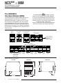
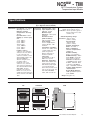
1
NCS
MIM
NET Concentrator ® System
with MODBUS Interface
September 2003
288-766-00 A
®
MIM
NCS
NET Concentrator System
with MODBUS Interface
Table of Contents
The NET Concentrator ® System ..................................................................... 3
About this Manual ............................................................................................................... 3
The MODBUS Interface Module (MIM) ............................................................ 4
Specifications–MIM ............................................................................................................. 5
Connecting the MIM to the MODBUS-RTU Network .......................................................5
Mounting ................................................................................................................................................... 5
Making the Connections............................................................................................................................ 6
PC Configuration Program ......................................................................... 8
Navigating the PC Program ........................................................................................... 10
The TIM Temperature Input Module ..............................................................11
The AIM Analog Input Module ......................................................................17
The AOM Analog Output Module ..................................................................22
The CPM NET Concentrator System Power Module ..................................27
The DIM Discrete Input Module.....................................................................30
The ROM Relay Output Module ....................................................................35
Appendix A: MODBUS RTU Support.......................................................... A-1
Appendix B: Loading a Custom Curve File............................................... A-3
Appendix C: Hot-Swapping a NET Concentrator® Module...................... A-5
Customer Service ......................................................................................... A-6
All product names are the property of their respective companies.
2
The Interface Solution Experts
NCSMIM
NET Concentrator ® System
with MODBUS Interface
The NET Concentrator®
System
This is the user’s manual for the Moore Industries NET
Concentrator® System (NCS), a modular family that
provides a link between dispersed field-mounted
process monitoring/control equipment and the control
room. The NCS transports just a few, or hundreds, of
process signals between the field or plant floor and
your control room on a single communications
network.
The NET Concentrator System is any combination of
one Interface Module with one or more I/O modules.
If there are multiple Interface Modules on one network,
the individual Interface Modules are termed stations,
while all the combined modules are called a system.
If there is a single Interface Module on a network, it
(and any attached I/O modules) is termed a system.
The Interface Module and one or more I/O modules
connect together via DB-25 connectors integrated into
the side(s) of each module. Any combination of input
and output modules may be used within a NET Concentrator System network. Power for up to two input/
output modules is supplied by the Interface Module. A
total of eight units can be powered by adding a NET
Concentrator System Power Module, or CPM.
About this Manual
Wherever you see a “Note”, “Caution”, or “WARNING ”
pay particular attention.
• A “Note” provides information to help you avoid
minor inconveniences during calibration,
installation, or operation of the NCS.
• A “Caution” provides information on steps to take in
avoiding procedures and practices that could risk
damage to the NCS or other equipment.
• A “WARNING ” provides information on steps to take
in avoiding procedures and practices that could
pose safety risks to personnel.
Figure 1. The NET Concentrator System Connects a Variety of Field Devices to Your Controller
CITECT
ICONICS
Intellution
US DATA
Wonderware
DCS, PLC,
or PC with
HMI/SCADA
(with NET
Concentrator
System
OPC Server)
MODBUS-RTU
Network
NET
Concentrator
System
Module
Number
Distributed Field Devices
Process Variable Transmitters
Temperature Sensors
Control Valves
Discrete Devices
Relays
The Interface Solution Experts
3
NCSMIM – MIM
NET Concentrator ® System
MODBUS Interface Module
Note:
The MIM MODBUS Interface Module provides
power for up to two Input and/or Output Modules.
If more than two I/O Modules will be connected to
the Interface Module, a CPM Concentrator Power
Module is required. The CPM may be installed at
any position within a NCS station.
It works in conjunction with the Interface Module to
power NCS stations of up to eight I/O Modules.
The MODBUS
Interface Module (MIM)
The MODBUS Interface Module (MIM) interfaces the
wide range of NET Concentrator I/O modules to
MODBUS RTU protocol. It regularly scans I/O modules for process and diagnostics data and maintains
its own database for quick access from two independent MODBUS RTU slave ports. Upon power-up, the
MIM automatically detects all I/O modules connected,
and uploads data needed from each module in order to
begin scanning.
Figure 2. NET Concentrator System stations consist of one MIM Interface Module combined with up to eight Input/Output Modules.
Interface
Module
Input or Output
Module
+
Input or Output Module
(Not Required)
NET Concentrator
System Station
Up to 8 Input/Output
Modules per Interface
Module (with
addition of a CPM)
=
+
Module
Number
Module
Number
Fully-Populated
NET Concentrator System Station
Module
Number
Module
Number
Interface CPM Power
Input
Module Supply Module Module
(Can be Installed
at Any Position
Within a Station)
Input
Module
Output
Module
Input
Module
Input
Module
Module
Number
Output
Module
Input
Module
Output
Module
Figure 3. MIM Dimensional Diagram
LEFT SIDE
RIGHT SIDE
MIM FRONT
MIM MODBUS INTERFACE MODULE
NCS NET CONCENTRATOR SYSTEM
RX1
TX1
READY
RX2
TX2
135mm
(5.3 in)
4
The Interface Solution Experts
POWER COMMS
74mm
(2.9 in)
STATUS
114mm
(4.5 in)
83mm
(3.3 in)
NCSMIM - MIM
NET Concentrator ® System
MODBUS Interface Module
Specifications
MIM MODBUS Interface Module
One Interface Module Required Per NET Concentrator System Station
Communi- Type:
cations Two independently
configurable RS-485 ports
(according to EIA RS-485,
1983)
Protocol Type:
MODBUS RTU for Peer-toHost Systems; Moore
Industries proprietary
protocol for Peer-to-Peer
Systems
Baud Rates: Any rate is
user selectable (1200, 2400,
4800, 9600, 19200, 38400
and 57600)
Configuration:
Accomplished using a PC
with RS-232 port and Moore
Industries’ Intelligent
Configuration Software
Performance Communication Range:
1.6km (1 mile) typical at
9600 baud over 20AWG
twisted pair; 0.8km (0.5 mile)
typical at 19200 baud
Data Access Time: Time to
detect or effect a change in
an I/O signal. For a
MODBUS master polling an
MIM station, it is the sum of
the 3 timing components
(consult the factory for peerto-peer system throughput):
1. Network Communication
Time: Depends on baud
rate, amount of system data
Performance and the number of different
Status and
(continued) polls
Fault
2. Scan Time: Time
Indicators
required by the EIM to scan
real-time data in all I/O
modules within an NCS
station (see “Module Scan
Time” specification for each
I/O module type and add
times for each I/O module in
the NCS station
3. Signal Response Time:
Time to convert between
physical I/O and digital
signals (see specification for
specific I/O type)
Ambient
OPC Server: Allows PCConditions
based software packages to
access data from the
MODBUS Interface Module
Isolation: 500Vrms,
continuous, and will
withstand 1000Vrms
dielectric strength test for
one minute with no
breakdown, between power
input, each MODBUS port,
case and terminals of other
attached NCS modules
Weight
Power Supply:
20-30Vdc/3.6W maximum
Diagnostic Data: Fault
information provided on the
following conditions: error in
one of the I/O modules;
RAM error; system
configuration error; I/O
module port failure
READY: Green LED
indicates the device has
initialized and is running
properly
STATUS: Red/Green LED,
normally green, turns red
when fault conditions within
the MIM are detected.
RX (one for each RS-485
port): Green LED flashes
as information is received
TX (one for each RS-485
port): Green LED flashes
as information is transmitted
Operating Range:
–40°C to +85°C
(–40°F to +185°F)
Storage Range:
–40°C to +85°C
(–40°F to +185°F)
Relative Humidity:
0-95%, non-condensing
RFI/EMI Protection:
20V/m @20-1000MHz, 1kHz
AM when tested according to
EN61000-4-3-1996
493 g (17.4 oz)
Specifications and information subject to change without notice.
Connecting the MIM
to the MODBUS RTU Network
Connecting the MIM to the MODBUS RTU network involves Making the Connections and PC Configuration
Program.
Mounting
The MIM is designed to snap easily onto 32mm,
G-type (EN50035) or 35mm Top Hat (EN50022) DINrails. Snap the MIM onto the DIN-rail, then snap additional NCS modules onto the DIN-rail to the right of the
EIM, and slide together until the DB25 connectors on
the side of the MIM connect completely with the unit
to its right.
The Interface Solution Experts
5
NCSMIM – MIM
NET Concentrator ® System
MODBUS Interface Module
Making the Connections
The MIM has five external connections: power, I/O
module interface connector, PC port (for configuration)
and two MODBUS RTU slave ports. Refer to Table 1
for requirements and Figure 4 for illustration.
Table 1. Assembling the equipment for NCS Hookup
MODBUS RTU
One or two shielded, twisted pair
Network Connection MODBUS RTU connections
Power Supply
To install the power supply into the terminals, insert a
small, flathead screwdriver into the pry slot, open wire
terminal and place wire.
MODBUS Connection
MODBUS RTU cabling should be shielded twisted pair.
The conductors connected to the “A” and “B” terminals
and the shield to the “S” terminal at one of the MIM’s
MODBUS ports. The second port can be connected to
a second network.
CE Conformity
Installation of any Moore Industries’ product that carries the CE compliance marking (Commission Electrotechnique) must adhere to their respective installation
guidelines in order to meet the requirements set forth
in applicable EMC (Electromagnetic Compatibility)
directive (EN61326). Consult the factory for additional
information.
Recommended Ground Wiring Practices
Moore Industries recommends the following ground
wiring practices:
• Any Moore Industries product in a metal case or
housing should be grounded.
• The NCS individual module bases are
mechanically grounded when installed onto the
DIN-rail.
Be sure the DIN-rail is connected to a system
safety earth ground before making any other con
nections.
• All input signals to, and output signals
from, Moore Industries’ products should be
wired using a shielded, twisted pair
technique. Shields are to be connected to an
earth or safety ground at one end only.
6
The Interface Solution Experts
Description
Device
Personal Computer
(for configuration)
24Vdc
IBM or compatible PC with:
20Mb free hard disk space
Microsoft Windows® 95, 98, 2000, ME,
or NT (Windows 98, 2000, ME and NT
may require additional RAM and hard
disk space. See your Windows manual
for details.)
Note:
The “S” terminals of the MIM’s MODBUS
ports are NOT case ground. The shield of
the MODBUS cable must be connected to
earth ground at some other point.
• The maximum length of unshielded input
and output signal wiring should be 2 inches.
Power Sourcing Parameters for General
Locations, Intrinsically Safe, and
Non-Incendive/Type N applications
In accordance with IEC 1010.1 Annex H (all
models), the input terminals must be connected
to and/or supplied from a certified energy limiting
Class 2 or a Separate Extra Low Voltage
(S.E.L.V.) power supply separated from all
mains by double/reinforced insulation.
NCSMIM - MIM
NET Concentrator ® System
MODBUS Interface Module
Figure 4. NET Concentrator System Connection Diagram
INPUTS/OUTPUTS
MIM
Module
Number
MIM MODBUS INTERFACE MODULE
CHANNEL 1
CHANNEL 2
CHANNEL 3
NCS NET CONCENTRATOR SYSTEM
CHANNEL 4
RX1
TX1
24Vdc
POWER
SUPPLY
+
POWER
A
B S
A
B S
READY
RX2
TX2
COMMS
STATUS
I/O MODULE
–
RS-232 PC Port
(for Configuration)
MODBUS Hookups
From Secondary
MODBUS Host
From Primary
MODBUS Host
RX1
RX1
TX1
A
B S
A
B S
POWER COMMS
READY
TX1
MODBUS Port 1
RX2
MODBUS Port 2
TX2
STATUS
POWER
A
B S
RX2
A
B S
TX2
COMMS
READY
STATUS
The Interface Solution Experts
7
NCSMIM – MIM
NET Concentrator ® System
MODBUS Interface Module
Figure 5. MIM Configuration Screen
PC Configuration Program
The MIM is a MODBUS RTU slave. It has two
independent MODBUS ports which can have different
port settings, including MODBUS address. Character
Formats supported include: N-8-2 (default), E-8-1 and
O-8-1.
You will need to connect your MIM to a PC through the
RS-232 port in order to configure it with the PC Configuration Program.
MODBUS Port 1 and MODBUS Port 2 can be configured independently. The configuration screen contains 2 sets of the following controls– one for
configuring each port.
After initializing the NCS Configuration Program (NCS
Config), perform the following steps in order to connect
your device to the network.
Verify that the Ready and Status leds on the MIM are
both green.
8
The Interface Solution Experts
1. Select the Communications drop down menu, and
click “Connect”. You may also click the “Connect”
icon from the Communications bar.
2. Next, the Configure Communciations screen appears. From the drop down menu select the Serial
Port that is to be used.
3. Select “OK” from the Attempting Connection screen
once the connection has been made.
4. Drop down the Communications menu again and
choose “Upload” (up arrow). You may also directly
click the “Upload” button from the Communciations
bar. The MIM Configuration Screen in Figure 5 will appear.
NCSMIM - MIM
NET Concentrator ® System
MODBUS Interface Module
Configuration
Process Data
After clicking the “Interface Module Settings” button
from the device tree or the “MODBUS Interface
Module” screen, the Interface Module Settings Screen
will appear (Figure 6) with the following parameters:
To monitor process data, click “Monitor Process Data”
from the device tree or the “MODBUS Interface
Module” screen. The screen in Figure 7 (below) appears. Screen set-up is detailed below.
Station Identification
This is an edit box that allows entry of a text description of the device.
Monitor Process Data
Check this box in order to monitor a log of your system processes.
Note:
Wherever an invalid value is entered in a text box, the
invalid data will turn red as a visual indication of the
illegal entry.
Update Rate (seconds)
The dropdown menu allows you to select how often
your screen is updated.
MODBUS Floating Point Word Order
This selection control allows choices of: Standard or
Swapped.
Address
The device Address parameter allows you to enter or
select values from 1 to 247 (default is “1”).
Data Precision (digits right of decimal)
Choose the amount of resolution you want to monitor
by selecting the value from the dropdown menu.
Status
Indicates the present status of your system.
Last Update
Indicates the last time that information was posted and
updated to your screen.
Figure 6. Interface Module Settings Screen
Figure 7. Process Data Screen
The Interface Solution Experts
9
NCSMIM – MIM
NET Concentrator ® System
MODBUS Interface Module
Navigating the PC Program
The following information applies to all modules connected to the MIM. It details instructions for manuevering
through the configuration program.
Channel Selection
There are various methods for selecting a device channel for configuration, you may use any of the following:
Open the module itself in the device tree by clicking the “+”.
In the device tree, double-click the desired device
to open it up and expose the channels.
Highlight the module itself in the device tree. In
the right-hand pane, buttons will appear for each channel in the selected module. Select the channel you
wish to configure.
You may also select the Edit dropdown menu and
click “Add Module”.
3. The selected module type with default module/
channel configuration will be added to the last module
position in the station.
4. You may Upload the configuration present in the
module or modify the configuration to your requirements and download the configuration to your system.
To Delete a Module
1. Ensure that the station is offline.
2. Right-click the module you want to delete and select “Delete” in the pop-up menu.
You may also select the Edit dropdown menu and
click “Delete”.
Settings
To Add a New Interface Module
When enabling Trimming or Custom Curve settings in
a channel, check the appropriate box in the right-hand
pane. Open the channel from the device tree and then
open the enabled setting. Proceed in configuring the
parameter.
To add another interface module into your system, select the File dropdown menu, highlight “New” click “Interface Module” and select “MIM”. Clicking the “New”
icon in the Communications bar will also automatically
add an MIM.
Adding and Removing Modules
You may also right-click any empty area within the device tree and select “New”, “Interface Module” and then
“MIM”.
Right-clicking is an important function in station configuration and in the addition or placement of modules
within the device tree.
Note:
When placing or replacing a module in your system
configuration, you must “Disconnect” from the
Communications drop down menu and cycle down
power before disconnecting or reconnecting to your
system. Once you have placed your desired
modules, you may reconnect and repeat the
steps in “Connecting to the Network”.
To Add a Module
1. Ensure that the station is offline. Highlight the
core device of the station to which the module is to be
added.
2. Right-click and select the “Add Module” pop-up
menu item. Select the desired module type.
10
The Interface Solution Experts
Saving Your Configuration
When saving your system configuration, you must
save with a “.xml” file extension.
Device Tree Indicators
You will notice different colored indicator lights in the
device tree. These are meant to indicate the status of
connected modules. For a guide to the meaning of
different colors, open the Help dropdown menu and
select “Tree Indicators Legend”.
Log
At the bottom of the NCS Configuration Software
screen is a log that indicates system messages and
operations. You may clear the log at any time by
right-clicking and selecting “Clear”.
NCSMIM - TIM
NET Concentrator ® System
Temperature Input Module
The TIM Temperature
Input Module
The Temperature Input Module (TIM) of the NCS
family isolates and conditions up to four temperature
signals and relays temperature information from these
inputs to the Interface Module.
Installing the TIM
Installation consists of physically mounting the unit,
completing the input connections, and grounding the
unit.
Mounting
The TIM is designed to snap easily onto 32mm,
G-type (EN50035) or 35mm Top Hat (EN50022) DINrails. Snap the TIM onto the DIN-rail to the right of the
NCS module, then slide it along the rail until the DB25
connectors on the side of the TIM connect completely
with the unit to its left. See Figure 8 for illustration.
Input Connections
After mounting, you are ready to connect the inputs to
the TIM. Since the TIM receives power from the
connected Interface Module, only the temperature
sensor inputs need to be connected. Figure 8 shows
the connection diagrams for the TIM.
“Hot Swapable” I/O Modules
Should an Input/Output Module need to be replaced,
simply program a new module, remove the old
module from the mounting base and snap in the new
one. For more specific instructions, see Appendix
C: Hot-Swapping a NET Concentrator Module.
CE Conformity
Installation of any Moore Industries’ product that
carries the CE compliance marking (Commission
Electro technique) must adhere to their respective
installation guidelines in order to meet the requirements
set forth in applicable EMC (Electromagnetic
Compatibility) directive (EN61326). Consult the factory
for additional information.
Recommended Ground Wiring Practices
Moore Industries recommends the following ground
wiring practices:
• Any Moore Industries product in a metal
case or housing should be grounded.
• The NCS individual module bases are
mechanically grounded when installed onto
the DIN-rail. Be sure the DIN-rail is
connected to a system safety earth ground
before making any other connections.
• All input signals to, and output signals
from, Moore Industries’ products should be
wired using a shielded, twisted pair
technique. Shields are to be connected to an
earth or safety ground near the unit itself.
• The maximum length of unshielded input
and output signal wiring should be 2 inches.
The Interface Solution Experts
11
NCSMIM – TIM
NET Concentrator ® System
Temperature Input Module
Figure 8. TIM Connection Diagram
INPUT CONNECTIONS
ATTACH THE TEMPERATURE
INPUTS TO THE TERMINALS
AT THE TOP OF THE TIM.
SPECIFIC CONNECTION
TYPES ARE SHOWN BELOW.
Module
Number
TIM TEMPERATURE INPUT MODULE
MIM MODBUS INTERFACE MODULE
CHANNEL 1
CHANNEL 2
CHANNEL 3
NCS NET CONCENTRATOR SYSTEM
INTERFACE MODULE
THE INTERFACE MODULE
SHOULD ALREADY BE
INSTALLED ON THE DIN-RAIL.
CHANNEL 4
CONNECTING THE TIM
SLIDE THE TIM ALONG
THE DIN-RAIL UNTIL THE
DB25 LINK CONNECTS
TO THE ADJACENT I/O
OR INTERFACE MODULE
RX1
TX1
READY
RX2
TX2
POWER COMMS
24VDC
POWER
SUPPLY
+
STATUS
TIM
INTERFACE MODULE
–
TERMINAL CONNECTIONS
THERMOCOUPLE
1
2
3
MILLIVOLT
1
4
+
1
2
3
–
POTENTIOMETER
3
4
+
2
4
–
INCREASING
4-WIRE RTD &
DIRECT RESISTANCE
1
2
3
12
The Interface Solution Experts
3-WIRE RTD &
DIRECT RESISTANCE
1
4
2
3
2-WIRE RTD &
DIRECT RESISTANCE
1
4
2
3
4
NCSMIM - TIM
NET Concentrator ® System
Temperature Input Module
Configuring the TIM
Settings
The TIM is configured using the PC Configuration
Program. To configure the TIM, you must first mount
it to the Interface Module as described in Installing the
TIM.
Filter-This setting is used to configure the input
filter which is designed to reduce the effects of
mains-induced noise. The frequency value should be
set to the frequency of the local AC supply.
After mounting, bring up the NCS configuration
software. Add a TIM to the device tree. The TIM
accepts four different temperature inputs, and uses a
separate channel for each. Select the channel you
wish to program. The screen shown in Figure 9 will
appear. See below for a description of the different
parts of the screen.
Custom Curve-Checking this box allows you to
setup a custom linearization table of up to 128 points
that will tell the TIM what value to output when a
certain input is received. This is accomplished by
loading into memory a comma-separated value file
(.csv) that was created in Excel® or a similar program.
For instructions, refer to Appendix B: Loading a
Custom Curve File.
Usage
Allows you to select “Channel Not Used”. Checking
this box will cause the TIM and its associated
Interface Module to ignore the selected channel,
allowing you to use less than all four channels without
receiving error messages.
Input Configuration
This programs the type of input that the TIM will
receive. Different measurement types require different
parameters to be programmed. Once an input type is
selected, the associated parameter fields will appear.
When a measurement type is selected, other
parameters may become red, indicating that the red
parameter must be programmed.
Input Ranging
Allows you to either input or capture the upper and
lower ranges that you want to have measured.
Input Scaling
Input Scaling allows you to take the input and convert
it to a different range. For example, you take a
channel with a 0-1000°C range and scale it to 0-100°C;
now when the input is 734°C, it is relayed to the
Interface Module as 73.4°C.
Trimming-Select the “Trimming” box to enable.
The TIM can be trimmed with an upper and lower trim
point. When arriving at the Trimming screen, select “1
Point Trim” or “2 Point Trim” in the Mode section.
Next, in the “Trim Point” text box, place the value you
wish to use. Depending on the parameter you are
setting, select the “Trim Lower” or “Trim Upper” box
and follow the instructions.
Ambient Temp-Check this box to compensate for
the effects of ambient temperature on thermocouple
wire. To read ambient temperature, select °C or °F
from the dropdown menu, and then refer to the
MODBUS Register Definitions table (Appendix A:
MODBUS RTU Support, Table A-1).
Broken Wire Detection-Upon selection of this
function, the TIM performs continuous sensor
diagnostics, monitoring the sensor and sending the
output upscale or downscale during a failure.
The Interface Solution Experts
13
NCSMIM – TIM
NET Concentrator ® System
Temperature Input Module
Figure 9. TIM Configuration Screen
14
The Interface Solution Experts
NCSMIM - TIM
NET Concentrator ® System
Temperature Input Module
Specifications
TIM Temperature Input Module (4 Channels)
(Up to Eight Per Interface Module)
Performance Input Ranges: See Table 2
Accuracy: See Table 2
Reference Junction
Compensation Accuracy:
±0.25°C
Input Resolution: 20-bit
Stability (% of max. span):
RTD:
1-year, 0.013%;
3-year, 0.023%;
5-year, 0.029%
Thermocouple:
1-year, 0.0084%;
3-year, 0.015%;
5-year, 0.019%
Isolation: 500Vrms,
continuous, from channel to
channel, from each channel
to case, and from each
channel to terminals of other
attached NCS modules; will
withstand 1000Vrms
dielectric strength test for
one minute, with no
breakdown, from each
channel to case, and from
each channel to terminals of
other attached NCS modules
Scan Time: The time
required for the Interface
Module to access process
variable and status data from
all four channels of the TIM is
16ms
Performance Response Time: 150ms
(continued) Input Impedance (T/C):
40Mohms, nominal
Maximum Input
Overrange: ±5Vdc peak,
maximum
Excitation Current
(RTD and Ohms):
250 microamps nominal
Power Supply:
Power is supplied by the
Interface Module, 1.5W
maximum
Linearization Capability:
Custom curve tables can be
configured with up to 128
points using Internet
Explorer web pages or
PC-based software
Input Filter:
Programmable for 50 or
60Hz noise rejection
Diagnostic Information:
Status data available when
polling channels includes
A/D saturated; input signal
out of linearized range;
broken RJC; broken sensor
wire (#1, #2, #3, or #4); runtime failure; EEPROM
failure; A/D converter fail
Status and One red/green LED per
Fault channel indicates proper
Indicators channel operation (green) or
that the channel is in a fault
condition (red)
Ambient Operating Range:
Conditions –40°C to +85°C
(–40°F to +185°F)
Storage Range:
–40°C to +85°C
(–40°F to +185°F)
Ambient Temperature
Effect: See Table 1
Effect on Reference
Junction Compensation:
±0.005°C/°C
Relative Humidity:
0-95%, non-condensing
RFI/EMI Immunity: 20V/m
@20-1000MHz, 1kHz AM
when tested according to
ENC6100-4-3-1996; Effect
on RTD/Ohms Input: 0.4°C/
0.1Ohms, maximum; Effect
on Thermocouple/Millivolt
Input: 1.0°C/40uV, maximum
Common Mode Rejection:
100dB@50/60Hz
Normal Mode Rejection:
50dB [email protected] peak-topeak, 50/60Hz
Weight 589 g (20.7 oz)
Specifications and information subject to change without notice.
Figure 10. TIM Dimensions
TOP
SIDE
TIM FRONT
TERMINAL BLOCK
IDENTIFICATION
CH1
CH2
CH3
CH4
1 2
3 4
1 2
3 4
1 2
3 4
1 2
3 4
Module
Number
TIM TEMPERATURE INPUT MODULE
CHANNEL 1
CHANNEL 2
CHANNEL 3
114mm
(4.5 in)
CHANNEL 4
TIM TEMPERATURE INPUT MODULE
MODULE
NUMBER
1
2
3
4
70mm
(2.8 in)
138mm
(5.4 in)
The Interface Solution Experts
15
NCSMIM – TIM
NET Concentrator ® System
Temperature Input Module
Table 8. TIM Temperature Input Type and Accuracy Table.
Input
Type
α
Ohms
RTD
(2-, 3-,
4-Wire)
Conformance
Range
Minimum
Span
Input
Accuracy
Maximum
Range
Ambient Temperature
Accuracy/°C Change
100
200
300
0.003850
400
-200 to 850°C
-328 to 1562°F
-240 to 960°C
-400 to 1760°F
500
1000
Platinum
10°C
(18°F)
100
0.0035°C (0.0063°F)
±0.1°C
(±0.18°F)
200
0.003902
400
-100 to 650°C
-148 to 1202°F
-150 to 720°C
-238 to 1328°F
-200 to 510°C
-328 to 950°F
-80 to 320°C
-112 to 608°F
-50 to 250°C
-58 to 482°F
±0.14°C
(±0.25°F)
±1.6°C
(±2.88°F)
-240 to 580°C
-400 to 1076°F
-100 to 360°C
-148 to 680°F
-65 to 280°C
-85 to 536°F
500
1000
0.003916
100
Nickel
0.00672
120
Copper
0.00427
9.035
Direct Resistance
Ohms
Potentiometer
T/C
mV
16
0-4000ohms
0-4000ohms
10ohms
±0.4ohms
0-4095ohms
100-4000ohms
0-100%
10%
±0.1%
0-100%
n/a
0.002°C (0.0036°F)
0.0035°C (0.0063°F)
0.002ohms + 0.005%
of reading
J
n/a
n/a
-180 to 760°C
-292 to 1400°F
35°C
(63°F)
±0.25°C
(±0.45°F)
-210 to 770°C
-346 to 1418°F
0.00016°C + 0.005%
of reading
K
n/a
n/a
-150 to 1370°C
-238 to 2498°F
40°C
(72°F)
±0.3°C
(±0.54°F)
-270 to 1390°C
-454 to 2534°F
0.0002°C +
0.005% of reading
E
n/a
n/a
-170 to 1000°C
-274 to 1832°F
35°C
(63°F)
±0.25°C
-270 to 1013°C 0.00026°C + 0.005%
(±0.45°F) -454 to 1855.4°F
of reading
T
n/a
n/a
-170 to 400°C
-274 to 752°F
35°C
(63°F)
±0.25°C
(±0.45°F)
-270 to 407°C
-454 to 764.6°F
0.0001°C +
0.005% of reading
R
n/a
n/a
0 to 1760°C
32 to 3200°F
50°C
(90°F)
±0.55°C
(±0.99°F)
-50 to 1786°C
-58 to 3246.8°F
0.00075°C + 0.005%
of reading
S
n/a
n/a
0 to 1760°C
32 to 3200°F
50°C
(90°F)
±0.55°C
(±0.99°F)
-50 to 1786°C
-58 to 3246.8°F
0.00075°C + 0.005%
of reading
B
n/a
n/a
400 to 1820°C
752 to 3308°F
75°C
(135°F)
±0.75°C
(±1.35°F)
200 to 1836°C
392 to 3336.8°F
0.0038°C +
0.005% of reading
N
n/a
n/a
-130 to 1300°C
-202 to 2372°F
45°C
(81°F)
±0.4°C
-270 to 1316°C
(±0.72°F) -454 to 2400.8°F
0.0003°C +
0.005% of reading
C
n/a
n/a
0 to 2300°C
32 to 4172°F
100°C
(180°F)
±0.8°C
(±1.44°F)
0 to 2338°C
32 to 4240.4°F
0.00043°C + 0.005%
of reading
DC
n/a
n/a
-50 to 1000mV
4 mV
15 microvolts
n/a
0.5 microvolts + 0.005%
The Interface Solution Experts
NCSMIM - AIM
NET Concentrator ® System
Analog Input Module
The AIM Analog
Input Module
The Analog Input Module (AIM) of the NCS family isolates and conditions four analog signals and relays input information to the Interface Module.
Installing the AIM
Installation consists of physically mounting the unit,
completing the input connections, and grounding the
unit.
Mounting
The AIM is designed to snap easily onto 32mm,
G-type (EN50035) or 35mm Top Hat (EN50022) DINrails. Snap the AIM onto the DIN-rail to the right of the
NCS unit, then slide it along the rail until the DB25
connectors on the side of the AIM connect completely
with the unit to its left. See Figure 11 for illustration.
Recommended Ground Wiring Practices
Moore Industries recommends the following ground
wiring practices:
Input Connections
After mounting, it is time to connect the analog inputs
to the AIM. Since the AIM receives power from the
connected Interface Module, only the analog inputs
need to be connected. Figure 11 shows the connection diagrams for an AIM.
“Hot Swapable” I/O Modules
Should an Input/Output Module need to be replaced,
simply program a new module, remove the old module
from the mounting base and snap in the new one. For
more specific instructions, see Appendix C: Hot-Swapping a NET Concentrator Module.
CE Conformity
Installation of any Moore Industries’ product that carries the CE compliance marking (Commission Electro
technique) must adhere to their respective installation
guidelines in order to meet the requirements set forth
in applicable EMC (Electromagnetic Compatibility)
directive (EN61326). Consult the factory for additional
information.
• Any Moore Industries product in a metal
case or housing should be grounded.
• The NCS individual module bases are
mechanically grounded when installed onto
the DIN-rail. Be sure the DIN-rail is
connected to a system safety earth ground
before making any other connections.
• All input signals to, and output signals
from, Moore Industries’ products should be
wired using a shielded, twisted pair
technique. Shields are to be connected to an
earth or safety ground near the unit itself.
• The maximum length of unshielded input
and output signal wiring should be 2 inches.
The Interface Solution Experts
17
NCSMIM – AIM
NET Concentrator ® System
Analog Input Module
Figure 11. AIM Connection Diagram
INPUT CONNECTIONS
ATTACH THE ANALOG
INPUTS TO THE TERMINALS
AT THE TOP OF THE AIM.
Module
Number
MIM MODBUS INTERFACE MODULE
AIM ANALOG INPUT MODULE
CHANNEL 1
CHANNEL 2
NCS NET CONCENTRATOR SYSTEM
CHANNEL 3
CHANNEL 4
INTERFACE MODULE
THE INTERFACE MODULE
SHOULD ALREADY BE
INSTALLED ON THE DIN-RAIL.
CONNECTING THE AIM
SLIDE THE AIM ALONG
THE DIN-RAIL UNTIL THE
DB25 LINK CONNECTS
TO THE ADJACENT I/O
OR INTERFACE MODULE
RX1
TX1
READY
RX2
TX2
POWER COMMS
+
24VDC
POWER
SUPPLY
STATUS
AIM
INTERFACE MODULE
–
TERMINAL CONNECTIONS
CURRENT INPUT
WITH TRANSMITTER
EXCITATION
1
CURRENT INPUT
WITHOUT TRANSMITTER
EXCITATION
2
1
VOLTAGE
INPUT
1
2
2
TX
Iin
TX
Iin
TX
Iin
Vin
Com
Vin
Com
Vin
Com
3
4
+PS –PS
3
4
–
3
+
4
–
+
NOTE: TO INSTALL WIRES INTO THE TERMINALS, INSERT A SMALL, FLATHEAD
SCREWDRIVER INTO THE PRY SLOT, OPEN WIRE TERMINAL AND PLACE WIRE.
18
The Interface Solution Experts
NCSMIM - AIM
NET Concentrator ® System
Analog Input Module
Configuring the AIM
Settings
The AIM is configured using the PC Configuration
Program. To configure the AIM, you must first mount
it to the Interface Module as described in Installing the
AIM.
Filter-This setting is used to configure the input
filter which is designed to reduce the effects of
mains-induced noise. The frequency value should be
set to the frequency of the local AC supply.
After mounting, bring up the NCS configuration
software. Add an AIM to the device tree. The AIM
accepts four different analog signals, and uses a
separate channel for each. Select the channel you
wish to program. The screen shown in Figure 12 will
appear. See below for a description of the different
parts of the screen.
Custom Curve-Checking this box allows you to
setup a custom linearization table of up to 128 points
that will tell the AIM what value to output when a
certain input is received. This is accomplished by
loading into memory a comma-separated value file
(.csv) that was created in Excel® or a similar program.
For instructions, refer to Appendix B: Loading a
Custom Curve File.
Usage
Allows you to select “Channel Not Used”. Checking
this box will cause the AIM and its associated
Interface Module to ignore the selected channel,
allowing you to use less than all four channels without
receiving error messages.
Input Type
This sets the type of input that the AIM will receive.
Different measurement types require different
parameters to be programmed. You may select
between “Volts” and “Current”. When a measurement
type is selected, other parameters may become red,
indicating that the red parameter must be programmed.
Trimming-Select the “Trimming” box to enable.
The AIM can be trimmed with an upper and lower trim
point. When arriving at the Trimming screen, select “1
Point Trim” or “2 Point Trim” in the Mode section.
Next, in the “Trim Point” text box, place the value you
wish to use. Depending on the parameter you are
setting, select the “Trim Lower” or “Trim Upper” box
and follow the instructions.
Input Ranging
Allows you to either input or capture the upper and
lower ranges that you want to have measured.
Input Scaling
Input Scaling allows you to take the input and convert
it to a different range. For example, you take a
channel with a 0-10V range and scale it to 0-100V; now
when the input is 7.34V, it is relayed to the Interface
Module as 73.4V.
The Interface Solution Experts
19
NCSMIM – AIM
NET Concentrator ® System
Analog Input Module
Figure 12. AIM Configuration Screen
20
The Interface Solution Experts
NCSMIM - AIM
NET Concentrator ® System
Analog Input Module
Specifications
AIM Analog Input Module (4 Channels)
Up to Eight Per Interface Module
Performance
Performance
Input Ranges:
Programmable for any range (continued)
within: Current, 0-25mA
(4mA minimum span) or
Voltage, –10V to +10V
(1V minimum span)
Accuracy: ±0.01% of
maximum span
Input Resolution: 20-bit
Stability (% of max. span):
Current:
1-year, 0.047%;
3-year, 0.081%;
5-year, 0.11%
Voltage:
1-year, 0.066%;
3-year, 0.11%;
5-year, 0.15%
Isolation: 500Vrms,
continuous, from channel to
channel, from each channel
to case, and from each
channel to terminals of other
attached NCS modules; will
withstand 1000Vrms
dielectric strength test for
one minute, with no
breakdown, from each
channel to case, and from
each channel to terminals of
other attached NCS modules
Scan Time: The time
required for the Interface
Module to access process
variable and status data from
all four channels of the AIM
is 16ms
Response Time: 60ms
Input Impedance:
Current, 20ohms;
Voltage, 1Mohm
Maximum Input
Overrange: Current,
±100mA;
Voltage, ±30V
Power Supply: Power is
supplied by the Interface
Module, 4W maximum
Input Filter: UserProgrammable for 50Hz or
60Hz noise rejection
Linearization Capability:
Custom curve tables can be
configured with up to 128
points using Internet
Explorer web pages or
PC-based software
Transmitter Excitation:
21V/24mA excitation for
powering a 2-wire
transmitter
Diagnostic Information:
Status data available when
polling channels includes
A/D saturated; input signal
out of linearized range;
EEPROM failure; A/D
converter failure; and
run-time failure
Status
and
Fault
Indicators
Ambient
Conditions
Weight
One red/green LED per
channel indicates proper
channel operation (green)
or that the channel is in a
fault condition (red)
Operating Range:
–40°C to +85°C
(–40°F to +185°F)
Storage Range:
–40°C to +85°C
(–40°F to +185°F)
Ambient Temperature
Effect: 0.01% of maximum
span/°C
Relative Humidity:
0-95%, non-condensing
RFI/EMI Protection: 20V/m
@20-1000MHz, 1kHz AM
when tested according to
ENC61000-4-3-1996.
Common Mode
Rejection:
100dB@50/60Hz
Normal Mode Rejection:
Current, 60dB
typical@10mA peak-topeak; Voltage, 60dB
typical@1V peak-to-peak,
50/60Hz
562 g (19.8 oz)
Specifications and information subject to change without notice.
Figure 13. AIM Dimensions
RIGHT SIDE
AIM FRONT
LEFT SIDE
Module
Number
AIM ANALOG INPUT MODULE
CHANNEL 1
CHANNEL 2
CHANNEL 3
CHANNEL 4
138mm
(5.4 in)
114mm
(4.5 in)
83mm
(3.3 in)
70mm
(2.8 in)
The Interface Solution Experts
21
NCSMIM – AOM
NET Concentrator ® System
Analog Output Module
The AOM Analog
Output Module
The Analog Output Module (AOM) accepts information
from the NCS and outputs it as one of four independently configurable analog signals.
Installing the AOM
Installation consists of physically mounting the unit,
completing the output connections, and grounding the
unit.
Mounting
The AOM is designed to snap easily onto 32mm,
G-type (EN50035) or 35mm Top Hat (EN50022) DINrails. Snap the AOM onto the DIN-rail to the right of
the NCS unit, then slide it along the rail until the DB25
connectors on the side of the AOM connect completely with the unit to its left. See Figure 14 for
illustration.
Recommended Ground Wiring Practices
Moore Industries recommends the following ground
wiring practices:
• Any Moore Industries product in a metal
case or housing should be grounded.
• The NCS individual module bases are
mechanically grounded when installed onto
the DIN-rail. Be sure the DIN-rail is
connected to a system safety earth ground
before making any other connections.
• All input signals to, and output signals
from, Moore Industries’ products should be
wired using a shielded, twisted pair
technique. Shields are to be connected to an
earth or safety ground at the unit itself.
• The maximum length of unshielded input
and output signal wiring should be 2 inches.
22
The Interface Solution Experts
Input and Output Connections
After mounting, it is time to connect the analog
outputs to the AOM. Since the AOM receives power
from the connected Interface Module, only the analog
outputs need to be connected. Figure 14 shows the
connection diagrams for an AOM.
“Hot Swapable” I/O Modules
Should an Input/Output Module need to be replaced,
simply program a new module, remove the old module
from the mounting base and snap in the new one. For
more specific instructions, see Appendix C: Hot-Swapping a NET Concentrator Module.
CE Conformity
Installation of any Moore Industries’ product that carries the CE compliance marking (Commission Electro
technique) must adhere to their respective installation
guidelines in order to meet the requirements set forth
in applicable EMC (Electromagnetic Compatibility) directive (EN61326). Consult the factory for additional
information.
NCSMIM - AOM
NET Concentrator ® System
Analog Output Module
Figure 14. AOM Connection Diagram
AOM
MIM MODBUS INTERFACE MODULE
AOM ANALOG OUTPUT MODULE
NCS NET CONCENTRATOR SYSTEM
INTERFACE MODULE
THE INTERFACE MODULE
SHOULD ALREADY BE
INSTALLED ON THE DIN-RAIL.
RX1
TX1
READY
RX2
TX2
POWER COMMS
24VDC
POWER
SUPPLY
+
STATUS
CONNECTING THE AOM
SLIDE THE AOM ALONG
THE DIN-RAIL UNTIL THE
DB25 LINK CONNECTS
TO THE ADJACENT I/O
OR INTERFACE MODULE
Module
Number
INTERFACE MODULE
OUTPUT CONNECTIONS
ATTACH THE ANALOG
OUTPUTS TO THE TERMINALS
ON THE BOTTOM OF THE AOM.
–
TERMINAL CONNECTIONS
CURRENT
SINK
CURRENT
SOURCE
1
2
1
2
3
4 -Iout
VOLTAGE
OUTPUT
1 2
-Iout
+Iout
3
4
3
+Iout
4
-Vout
+Vout
NOTE: TO INSTALL WIRES INTO THE TERMINALS, INSERT A SMALL, FLATHEAD
SCREWDRIVER INTO THE PRY SLOT, OPEN WIRE TERMINAL AND PLACE WIRE.
The Interface Solution Experts
23
NCSMIM – AOM
NET Concentrator ® System
Analog Output Module
Configuring the AOM
The AOM is configured using the PC Configuration
Program. To configure the AOM, you must first mount
it to the Interface Module as described in Installing the
AOM.
After mounting, bring up the NCS configuration
software. Add a AOM to the device tree. The AOM
outputs four different analog signals, and uses a
separate channel for each. Select the channel you
wish to program. The screen shown in Figure 15 will
appear. See below for a description of the different
parts of the screen.
Usage
Allows you to select “Channel Not Used”. Checking
this box will cause the AOM and its associated
Interface Module to ignore the selected channel,
allowing you to use less than all four channels without
receiving error messages.
Output Type
This programs the AOM to output either “Volts” or
“Current”. When an Output Type is selected, other
parameters may become red, indicating that these
parameters must be programmed.
Output Ranging
Allows you to enter the upper and lower ranges that
you want the AOM to output.
Output on Out-of-Range PV
These boxes allow you to enter the value that you want
the AOM’s output to return to (as a default) when the
monitored input goes out of range.
Loop Test
This function allows you test the other instruments on
the loop by setting the AOM to output a specific value.
After clicking Loop Test, use the arrows to select the
desired value and press Set to begin.
Output Scaling
Output scaling allows you to access the analog output
process variable in a number range more meaningful to
you than the acutal mA or Volts output. For example,
if the actual output range is 4-20mA, set the scaled
range to 0-100; you now write “0” to the process
variable to get 4mA out and “100” to get 20mA out.
Output on Failure
This section tells the AOM what to do when the
monitored input fails entirely. It will either maintain the
last value (Hold Last), or jump to a predefined value
that you input (Preset Predefined Value).
Settings
Trimming-The AOM can be trimmed with two data
points within the selected zero and span output range.
This allows a complete range to be output, while
placing an emphasis on a specific segment of the
range most critical to the process.
Output Damping-Allows you to introduce a delay
into the AOM’s response to a change in input. The
value of the output damping is the number of seconds
that it will take for a display to make a 63% change in
response to the chane in input. A damping of “0” will
disable damping.
24
The Interface Solution Experts
NCSMIM - AOM
NET Concentrator ® System
Analog Output Module
Figure 15. AOM Configuration Screen
The Interface Solution Experts
25
NCSMIM – AOM
NET Concentrator ® System
Analog Output Module
Specifications
AOM Analog Output Module (4 Channels)
Up to Eight per Interface Module
Performance
Performance
Output Ranges:
Programmable for any range (continued)
within: Current (sink or
source), 0-20mA or Voltage,
0-10V
Accuracy: ±0.015% of
maximum span
Output Resolution: 18-bit
Stability (% of max. span):
Current:
1-year, 0.012%;
3-year, 0.020%;
5-year, 0.026%
Voltage:
1-year, 0.066%;
3-year, 0.11%;
5-year, 0.15%
Isolation: 500Vrms,
continuous, from channel to
channel, from each channel
to case, and from each
channel to terminals of other
attached NCS modules; will
withstand 1000Vrms
dielectric strength test for
one minute, with no
breakdown, from each
channel to case, and from
each channel to terminals of
other attached NCS modules
Scan Time: The time
required for the Interface
Module to access process
variable and status data from
all four channels of the AOM
is 16ms
Response Time:
50ms to 90% of final value
on a step input
Output Damping:
Increases response time
by adjusting filter time
constant from 0-30
seconds
Ripple: Current, 10mV
peak-to-peak measured
across a 250ohm load
resistor; Voltage, 50mV
peak-to-peak maximum
Load Capability:
Current, 0-1000ohms
(source), 42V maximum
(sink) 1500ohms;
Voltage, 0-50mA
(2000ohms minimum
load)
Output Limiting:
Current output is
guaranteed up to 21.6mA
(or 10% of full scale
above the programmed
full value) and limits at
23.6mA; Voltage output
accuracy is guaranteed
up to 10.5V (or 5% of full
scale above the
programmed full value)
and limits at 11.0V
Load Effect (current
outputs): 0.01% of span
from 0 to maximum load
resistance on current
output
Output Failure Mode:
Outputs are
programmable to either
hold last value or go to a
pre-defined value on error
Performance upon lost communication with
(continued) the Interface Module or upon
receiving invalid primary
variable data
Power Supply:
Power is supplied by the
Interface Module,
4W maximum
Diagnostic Information:
Status data available when
polling channels includes
ROM failure; RAM failure;
EEPROM; open current
output; EEPROM checksum
error
Status One red/green LED per
and Fault channel indicates proper
Indicators channel operation (green) or
that the channel is in a fault
condition (red)
Ambient Operating Range:
Conditions –40°C to +85°C
(–40°F to +185°F)
Storage Range:
–40°C to +85°C
(–40°F to +185°F)
Ambient Temperature
Effect: 0.01% of maximum
span/°C
Relative Humidity:
0-95%, non-condensing
RFI/EMI Protection:
20V/m@20-1000MHz, 1kHz
AM when tested according to
ENC61000-4-3-1996
Weight 765 g (27 oz)
Specifications and information subject to change without notice.
Figure 16. AOM Dimensions
AOM FRONT
LEFT SIDE
RIGHT SIDE
AOM ANALOG OUTPUT MODULE
114mm
(4.5 in)
Module
Number
138mm
(5.4 in)
26
The Interface Solution Experts
70mm
(2.8 in)
83mm
(3.3 in)
NCSMIM - CPM
NET Concentrator ® System
Power Module
Recommended Ground Wiring Practices
Moore Industries recommends the following ground
wiring practices:
The CPM NET Concentrator
System Power Module
Normally, an Interface Module can only power two I/O
modules; the CPM provides additional power, allowing
a total of eight I/O modules of any type to be attached
to one Interface Module.
• Any Moore Industries product in a metal
case or housing should be grounded.
• The NCS individual module bases are
mechanically grounded when installed onto
the DIN-rail. Be sure the DIN-rail is
connected to a system safety earth ground
before making any other connections.
Installing the CPM
Installation consists of physically mounting the unit,
making the power connections, and grounding the unit.
• The maximum length of unshielded input
and output signal wiring should be 2 inches.
Mounting
The CPM is designed to snap easily onto 32mm,
G-type (EN50035) or 35mm Top Hat (EN50022) DINrails. Snap the CPM onto the DIN-rail to the right of
any module within the NCS station, then slide it along
the rail until the DB25 connectors on the side of the
CPM connect completely with the unit to its left.
The CPM can be installed at any position within a
NET Concentrator System.
Figure 17. CPM Connection Diagram
CPM
INPUTS/OUTPUTS
Module
Number
CPM NCS POWER MODULE
CHANNEL 1
TO INTERFACE
OR I/O MODULE
CHANNEL 2
CHANNEL 3
CHANNEL 4
READY
STATUS
24VDC
POWER
SUPPLY
POWER
+
I/O MODULE
–
The Interface Solution Experts
27
NCSMIM – CPM
NET Concentrator ® System
Power Module
Specifications
CPM Power Supply Module
One Required Per NET Concentrator System Station if There Are More Than Two Input/Output Modules
Performance Inputs (Power):
20-30Vdc
Output (Power): Provides
power to up to eight NCS
I/O modules
Isolation: 500Vrms,
continuous, and will withstand
1000Vrms dielectric strength
test for 1 minute with no
breakdown, between power
input, each Modbus port,
case and terminals of other
attached NCS modules
Startup Time: 10ms
Power Consumption:
40W maximum
Status and
Fault
Indicators
Ambient
Conditions
Power LED: A green LED
turns on to indicate that
power is being supplied to
the power terminals.
Status LED: A green LED
turns on to indicate that
power is available at the
CPM module’s output
Ambient Relative Humidity:
Conditions 0-95%, non-condensing
(continued) RFI/EMI Protection:
20V/m@20-1000MHz, 1kHz
AM when tested according to
ENC61000-4-3-1996
Weight 585 g (20.7 oz)
Operating Range:
–40°C to +85°C
(–40°F to +185°F)
Storage Range:
–40°C to +85°C
(–40°F to +185°F)
Specifications and information subject to change without notice.
Figure 18. CPM Dimensions
LEFT SIDE
CPM FRONT
RIGHT SIDE
CPM NCS Power Module
114mm
(4.5 in)
READY
STATUS
135mm
(5.3 in)
28
The Interface Solution Experts
POWER
74mm
(2.9 in)
83mm
(3.3 in)
NCSMIM - CPM
NET Concentrator ® System
Power Module
Note:
The MIM MODBUS Interface Module provides power
for up to two Input and/or Output Modules.
If more than two I/O Modules will be connected to the
Interface Module, a CPM Concentrator Power Module is
required. The CPM may be installed at any position
within a NCS station.
It works in conjunction with the Interface Module to
power NCS stations of up to eight I/O Modules.
CE Conformity
Installation of any Moore Industries’ product that carries the CE compliance marking (Commission Electro
technique) must adhere to their respective installation
guidelines in order to meet the requirements set forth
in applicable EMC (Electromagnetic Compatibility) directive (EN61326). Consult the factory for additional
information.
Power Connections
After mounting, it is time to power the CPM. Attach
20-30Vdc power as shown in Figure 17.
Power Sourcing Parameters for General
Locations, Intrinsically Safe, and
Non-Incendive/Type N applications
In accordance with IEC 1010.1 Annex H (all models),
the input terminals must be connected to and/or
supplied from a certified energy limiting Class 2 or a
Separate Extra Low Voltage (S.E.L.V.) power supply
separated from all mains by double/reinforced insulation.
The Interface Solution Experts
29
NCSMIM – DIM
NET Concentrator ® System
Discrete Input Module
The DIM Discrete
Input Module
The Discrete Input Module (DIM) of the NCS family
isolates and conditions up to eight discrete signals,
and relays input information to the Interface Module.
The DIM is available for three different discrete input
channel types: contact closure, high range voltage, or
low range voltage. See the NCS Data Sheet for more
information on module types and options.
Installing the DIM
Installation consists of physically mounting the unit,
completing the input connections, and grounding the
unit.
Mounting
The DIM is designed to snap easily onto 32mm,
G-type (EN50035) or 35mm Top Hat (EN50022) DINrails. Snap the DIM onto the DIN-rail to the right of the
NCS unit, then slide it along the rail until the DB25
connectors on the side of the DIM connect completely
with the unit to its left. See Figure 18 for illustration.
Recommended Ground Wiring Practices
Moore Industries recommends the following ground
wiring practices:
• Any Moore Industries product in a metal
case or housing should be grounded.
• The NCS individual module bases are
mechanically grounded when installed onto
the DIN-rail. Be sure the DIN-rail is
connected to a system safety earth ground
before making any other connections.
• All input signals to, and output signals
from, Moore Industries’ products should be
wired using a shielded, twisted pair
technique. Shields are to be connected to an
earth or safety ground near the unit itself.
• The maximum length of unshielded input
and output signal wiring should be 2 inches.
30
The Interface Solution Experts
Input Connections
After mounting, it is time to connect the discrete inputs to the DIM. Since the DIM receives power from
the connected Interface Module, only the discrete inputs need to be connected. Figure 18 shows the connection diagrams for the DIM.
“Hot Swapable” I/O Modules
Should an Input/Output Module need to be replaced,
simply program a new module, remove the old module
from the mounting base and snap in the new one. For
more specific instructions, see Appendix C: Hot-Swapping a NET Concentrator Module.
CE Conformity
Installation of any Moore Industries’ product that carries the CE compliance marking (Commission Electro
technique) must adhere to their respective installation
guidelines in order to meet the requirements set forth
in applicable EMC (Electromagnetic Compatibility) directive (EN61326). Consult the factory for additional
information.
NCSMIM - DIM
NET Concentrator ® System
Discrete Input Module
Figure 19. DIM Connection Diagram
INPUT CONNECTIONS
ATTACH THE DISCRETE
INPUTS TO THE TERMINALS
AT THE TOP OF THE DIM.
Module
Number
MIM MODBUS INTERFACE MODULE
DIM-V DISCRETE INPUT MODULE
NCS NET CONCENTRATOR SYSTEM
INTERFACE MODULE
THE INTERFACE MODULE
SHOULD ALREADY BE
INSTALLED ON THE DIN-RAIL.
READY
RX2
TX2
POWER COMMS
+
24VDC
POWER
SUPPLY –
CHANNEL 5
CHANNEL 2
CHANNEL 6
CHANNEL 3
CHANNEL 7
CHANNEL 4
CHANNEL 8
CONNECTING THE DIM
SLIDE THE DIM ALONG
THE DIN-RAIL UNTIL THE
DB25 LINK CONNECTS
TO THE ADJACENT I/O
OR INTERFACE MODULE
RX1
TX1
CHANNEL 1
STATUS
DIM
INTERFACE MODULE
TERMINAL CONNECTIONS
(TYPICAL)
VOLTAGE
INPUT
CONTACT
CLOSURE INPUT
1
1
2
2
+
–
NOTE: TO INSTALL WIRES INTO THE TERMINALS, INSERT A SMALL, FLATHEAD
SCREWDRIVER INTO THE PRY SLOT, OPEN WIRE TERMINAL AND PLACE WIRE.
The Interface Solution Experts
31
NCSMIM – DIM
NET Concentrator ® System
Discrete Input Module
Configuring the DIM
The DIM is configured using the PC Configuration Program. To configure the DIM, you must first mount it to
the Interface Module as described in Installing the
DIM.
After mounting, bring up the NCS configuration software. Add your DIM to the device tree. See below for
a description of the different parts of the screen.
DIM Discrete Contact Closure Input Module
(DIMCC)
With the DIM Discrete Contact Closure Input Module
(DIMCC) the only configurable parameter is debounce
time. Once you have accessed the NCS configuration
software, select the DIM (CC8) module in the device
tree. This will display the screen shown in Figure 20.
32
The Interface Solution Experts
Settings
Contact Debounce-When some contacts open or
close, there can be a short period of oscillation resulting from the mechanical contacts. The Contact
Debounce setting causes the NCS to ignore false signals caused by these oscillations. This setting is only
available with contact closure DIM (DIMCC) modules.
DIM Discrete Voltage Input Module (DIMV)
There are no configurable parameters within the DIMV.
Its configuration is hard-wired. Once the module is
added to the device tree and its configuration uploaded, it is brought into the system. A heading in the
device tree identifies whether the DIMV is a Low or
High Range unit. Figure 21 displays the screen that
will appear once the unit is introduced into the system.
NCSMIM - DIM
NET Concentrator ® System
Discrete Input Module
Figure 20. DIMCC Configuration Screen
Figure 21. DIMV High and Low Range Configuration Screen
The Interface Solution Experts
33
NCSMIM – DIM
NET Concentrator ® System
Discrete Input Module
Specifications
DIM Discrete Contact Closure Input Module (8 Channels)
Up to Eight Per Interface Module
Performance Input Ratings: 24V/3.7mA,
internally powered
Input Logic Threshold:
8V low-going; 16V high-going
Input Logic: Closed contact
input yields logic 1
Isolation: 500Vrms,
continuous, from channel to
channel, from each channel
to case, and from each
channel to terminals of other
attached NCS modules; will
withstand 1000Vrms
dielectric strength test for one
minute, with no breakdown,
from each channel to case,
Performance and from each channel to
(continued) terminals of other attached NCS
modules
Scan Time: 4ms
Response Time: <12ms with
contact debounce disabled
Power Supply: Power is
supplied by the Interface
Module, 3W maximum
Diagnostic Information:
Status data available when
polling channels, includes:
ROM failure; RAM failure;
EEPROM checksum error
Ambient Operating Range:
Conditions –40°C to +85°C
(–40°F to +185°F)
Storage Range:
–40°C to +85°C
(–40°F to +185°F)
Relative Humidity:
0-95%, non-condensing
RFI/EMI Protection:
20V/m @20-1000MHz, 1kHz
AM when tested according to
IEC1000-4-3-1995
Weight 493 g (17.4 oz)
LED One red/green LED per channel
Indicators indicates input state, with red
indicating open contact input
DIM Discrete Voltage Input Module (8 Channels)
Up to Eight Per Interface Module
Performance Input Ratings: Low Range,
30Vac/Vdc; High Range:
120/240Vac/Vdc
Input Logic Threshold:
Low Range: <9Vac/Vdc
guaranteed low, >15Vac/Vdc
guaranteed high;
High Range: <55Vac
guaranteed low, >90Vac
guaranteed high
Input Logic: Input above
threshold yields logic 1; Input
below threshold yields logic 0
Input Impedance: Each
input draws <4mA when on
Isolation: 500Vrms,
continuous, from channel to
channel, from each channel
to case, and from each
channel to terminals of other
Performance attached NCS modules; will
(continued) withstand 1000Vrms
dielectric strength test for one
minute, with no breakdown,
from each channel to case,
and from each channel to
terminals of other attached
NCS modules
Scan Time: 4ms
Response Time: <30ms
Maximum Input Overrange:
Up to 260Vac/Vdc
Power Supply: Power is
supplied by the Interface
Module, 1W maximum
Diagnostic Information:
Status data available when
polling channels, includes:
ROM failure; RAM failure;
EEPROM checksum error
LED
Indicators
One red/green LED per
channel indicates input state,
with red indicating input below
threshold
Ambient
Conditions
Operating Range:
–40°C to +85°C
(–40°F to +185°F)
Storage Range:
–40°C to +85°C
(–40°F to +185°F)
Relative Humidity:
0-95%, non-condensing
RFI/EMI Protection:
20V/m @20-1000MHz, 1kHz
AM when tested according to
IEC1000-4-3-1995
Weight
Figure 22. DIM Dimensions
LEFT SIDE
RIGHT SIDE
DIM FRONT
Module
Number
DIM-V DISCRETE INPUT MODULE
CHANNEL 1
CHANNEL 5
CHANNEL 2
CHANNEL 6
CHANNEL 3
CHANNEL 7
CHANNEL 4
CHANNEL 8
138mm
(5.4 in)
70mm
(2.8 in)
34
The Interface Solution Experts
114mm
(4.5 in)
83mm
(3.3 in)
536 g (18.8 oz)
NCSMIM - ROM
NET Concentrator ® System
Relay Output Module
The ROM Relay
Output Module
The Relay Output Module (ROM) accepts information
from the NCS and outputs it to either four or eight
independently configurable relay signals.
Installing the ROM
Installation consists of physically mounting the unit,
completing the output connections, and grounding the
unit.
Mounting
The ROM is designed to snap easily onto 32mm,
G-type (EN50035) or 35mm Top Hat (EN50022) DINrails. Snap the ROM onto the DIN-rail to the right of
the NCS unit, then slide it along the rail until the DB25
connectors on the side of the ROM connect completely with the unit to its left. See Figure 23 for
illustration.
Input Connections
After mounting, it is time to connect the relay outputs
to the ROM. Since the ROM receives power from the
connected Interface Module, only the relay outputs
need to be connected. Figure 23 shows the connection diagrams for a ROM.
“Hot Swapable” I/O Modules
Should an Input/Output Module need to be replaced,
simply program a new module, remove the old module
from the mounting base and snap in the new one. For
more specific instructions, see Appendix C: Hot-Swapping a NET Concentrator Module.
CE Conformity
Installation of any Moore Industries’ product that carries the CE compliance marking (Commission Electro
technique) must adhere to their respective installation
guidelines in order to meet the requirements set forth
in applicable EMC (Electromagnetic Compatibility) directive (EN61326). Consult the factory for additional
information.
Recommended Ground Wiring Practices
Moore Industries recommends the following ground
wiring practices:
• Any Moore Industries product in a metal
case or housing should be grounded.
• The NCS individual module bases are
mechanically grounded when installed onto
the DIN-rail. Be sure the DIN-rail is
connected to a system safety earth ground
before making any other connections.
• All input signals to, and output signals
from, Moore Industries’ products should be
wired using a shielded, twisted pair
technique. Shields are to be connected to an
earth or safety ground near the unit itself.
• The maximum length of unshielded input
and output signal wiring should be 2 inches.
The Interface Solution Experts
35
NCSMIM – ROM
NET Concentrator ® System
Relay Output Module
Figure 23. ROM Connection Diagram
ROM
MIM MODBUS INTERFACE MODULE
ROM RELAY OUTPUT MODULE
NCS NET CONCENTRATOR SYSTEM
INTERFACE MODULE
THE INTERFACE MODULE
SHOULD ALREADY BE
INSTALLED ON THE DIN-RAIL.
RX1
TX1
READY
RX2
TX2
POWER COMMS
24VDC
POWER
SUPPLY
+
STATUS
CONNECTING THE ROM
SLIDE THE AOM ALONG
THE DIN-RAIL UNTIL THE
DB25 LINK CONNECTS
TO THE ADJACENT I/O
OR INTERFACE MODULE
Module
Number
INTERFACE MODULE
OUTPUT CONNECTIONS
ATTACH THE RELAY
OUTPUTS TO THE TERMINALS
ON THE BOTTOM OF THE ROM.
–
TERMINAL CONNECTIONS
RELAY OUTPUT
1
2
NOTE: TO INSTALL WIRES INTO THE TERMINALS, INSERT A SMALL, FLATHEAD
SCREWDRIVER INTO THE PRY SLOT, OPEN WIRE TERMINAL AND PLACE WIRE.
36
The Interface Solution Experts
NCSMIM - ROM
NET Concentrator ® System
Relay Output Module
Configuring the ROM
The ROM is configured using the PC Configuration
Program. To configure the ROM, you must first
mount it to the Interface Module as described in
Installing the ROM.
Output On Fail
This section tells the ROM what to do if
communication with the Interface Module fails. It will
either maintain the last value (Hold), or turn the relay to
a predetermined energized or de-energized state (On/
Off).
After mounting, bring up the NCS configuration
software. Add your ROM to the device tree. See
below for a description of the different parts of the
screen.
LEDs When Energized
Allows you to input the color (red or green) of the LED
when the relay is energized.
Once you have accessed the NCS configuration
software, click on I/O Module, then Configure Relay
Output Module. This will display the screen shown in
Figure 24. If you are installing a ROM4, you will see
the same screen except with four configurable
channels.
Output Test
This function allows you to change the state of each
relay. After clicking Output Test, use the check boxes
to select the desired relay and press “Apply” . A
checked box energizes the corresponding relay. To
display the current status of your Output Test, click
“Read”.
Configure the parameters listed on the screen. See
below for a description of the different parts of the
screen.
Power Up State
Checking a box configures the corresponding relay to
be on (energized) upon power up.
The Interface Solution Experts
37
NCSMIM – ROM
NET Concentrator ® System
Relay Output Module
Figure 24. ROM8 Configuration Page
38
The Interface Solution Experts
NCSMIM - ROM
NET Concentrator ® System
Relay Output Module
Specifications
ROM Relay Output Module (4 or 8 Channels)
Up to Eight Per Interface Module
Performance Mechanical Output
Ratings: 4-Channel Model:
SPDT relay, 1 form C, rated
2A@250Vac, 50/60Hz, noninductive, or 2A@30Vdc
8-Channel Model: SPST
relay, 1 form A or B, rated
2A@250Vac, 50/60Hz,
non-inductive, or 2A@30Vdc
Output Logic: Logic 1
yields energized relay
Output Failure Mode:
Outputs are programmable to
either hold last value, or go
energized or de-energized
upon lost communication with
the Interface Module
Scan Time: 4ms
Isolation: 500Vrms,
Performance continuous, from channel to
(continued) channel, from each channel
to case, and from each
channel to terminals of other
attached NCS modules; will
withstand 1000Vrms
dielectric strength test for one
minute, with no breakdown,
from each channel to case,
and from each channel to
terminals of other attached
NCS modules
Response Time: <10ms
Power Supply: Power is
supplied by the Interface
Module, 3W maximum
Diagnostic Information:
Status data available when
polling channels, includes:
ROM failure; RAM failure;
EEPROM checksum error
LED
Indicators
One red/green LED per
channel indicates relay state
and can be programmed for
desired sense
Ambient
Conditions
Operating Range:
–40°C to +85°C
(–40°F to +185°F)
Storage Range:
–40°C to +85°C
(–40°F to +185°F)
Relative Humidity:
0-95%, non-condensing
RFI/EMI Protection: 20V/m
@20-1000MHz, 1kHz AM
when tested according to
IEC1000-4-3-1995
Weight
493 g (17.4 oz)
Figure 25. ROM Dimensions
ROM FRONT
LEFT SIDE
RIGHT SIDE
ROM8 RELAY OUTPUT MODULE
CHANNEL 1
CHANNEL 5
CHANNEL 2
CHANNEL 6
CHANNEL 3
CHANNEL 7
CHANNEL 4
CHANNEL 8
114mm
(4.5 in)
83mm
(3.3 in)
Module
Number
138mm
(5.4 in)
70mm
(2.8 in)
The Interface Solution Experts
39
NCSMIM
NET Concentrator® System
with MODBUS Interface
Appendix A: MODBUS RTU
Support
Each NCS Interface Module is designed to be
accessed using either a supplied OPC server or
MODBUS communication. Directions for connecting
to the OPC server can be found in the installation section for your Interface Module. The section below supplies all of the information necessary to reference the
MODBUS register map and program a generic
MODBUS RTU OPC server, or other MODBUS RTU
master.
The MIM acts as independent MODBUS RTU slave on
each of the two RS-485 ports. The MODBUS registers
allow access to process variable data and status information. See Table A-1 for a complete list of available
MODBUS Registers.
Reading Primary Variables
Process variables are read using MODBUS function
code 3 or 4. Each 32-bit floating-point process variable will be mapped to two MODBUS registers; the
lower numbered MODBUS register will hold the leastsignificant-word (LSW), and the higher numbered
MODBUS register will hold the most-significant-word
(MSW) of the 32-bit value. For MODBUS masters that
use swapped floating point, the MIM has a configuration setting to change the default word order which is
(LSW).
Reading Device Status
Diagnostic data is read using MODBUS function codes
1 to 4. Each 16-bit status register will be one
MODBUS integer register, accessible using function
codes 3 or 4. When using function codes 1 or 2, the
16 status register bits are mapped to 16 consecutive
cells, with the status register’s least-significant-bit in
the lowest addressed cell.
Communicating with NET Concentrator Modules
At startup, the Interface Module will perform an initialization sequence to detect all connected NCS I/O
modules. If it recognizes the connected device, it will
mark the module as active in preparation for data
scanning.
After detecting connected NCS modules, the Interface
Module will begin continuous polling for the current
process variable and status of each module. The
returned data is stored locally by the Inteface Module
for access by the configuration software,
MODBUS RTU master or OPC server.
Table A-1. MODBUS Register Definitions
Number of MODBUS
Registers
Function
Code
Data
Type
2
3, 4, 6,
or 16
Float
2000
1
3 or 4
Integer
Interface Module
Status Flags
2000 + B
1
1 or 2
Discrete
Base Fail Register
2001
1
3 or 4
Integer
Module Fail Register
2002
1
3 or 4
Integer
Base Fail Flags
2015 + M
1
1 or 2
Discrete
Module Fail Flags
2031 + M
1
1 or 2
Discrete
Channel Status Register
2002 + 4(M – 1) + C
1
3 or 4
Integer
Channel Status Flags
2048 + 64(M – 1) + 16(C – 1) + B
1
1 or 2
Discrete
Discrete Primary Variable
8(M – 1) + C
1
1-6, 15 or 16*
Discrete
Discrete Module
Status Register
2003 + 4(M – 1)
1
3 or 4
Integer
Discrete Module
Status Flags
2048 + 64(M – 1) + B
1
1 or 2
Discrete
Variable Name
Register Reference
Primary Variable
1 + 8(M – 1) + 2(C – 1)
Ambient Temperature
201 + 8(M – 1) + 2(C – 1)
Interface Module
Status Register
In Register Reference:
M represents module
position (1-8);
C represents channel
number (1-4);
B represents bit position
(0-15) within the Interface
Module’s register.
*When using function codes
3, 4, 6, or 16, one discrete
primary variable is delivered
per MODBUS register, with a
non-zero integer value
representing logic 1.
The Interface Solution Experts
A-1
NCSMIM
NET Concentrator® System
with MODBUS Interface
NET Concentrator Module StatusThe I/O status register obtained during data scanning is used to create a
16-bit status word. The status word can be read using
MODBUS RTU as described earlier. The status register bits are defined in Table A-2. An error is indicated
by a set bit or any combination of set bits.
Table A-2. Interface Module Status Register
Bit Position
Description
15
14
13
12
11
Reserved
Reserved
Reserved
Reserved
Reserved
8
Indicates a failure to start one or more services.
4
Missing system configuration file.
3
New file system. Indicates that the EEC has formatted the file system. Normally, this is only performed once at the
initial system startup. However, an automatic format can occur if the file system becomes corrupted.
2
File system initialization error. Indicates that the EEC cannot determine the state of the file system.
Depending on the type of error, the EEC may attempt to automatically format the file system.
1
RAM test failed. This bit is set when a read/write error occurs during the power-on RAM test.
0
Slave device error. Typically used to indicate an error in any attached I/O devices.
Table A-3. TIM Channel Status Register/Bit Positions
Bit
Position
11
10
9
8
7
6
5
4
3
2
1
0
Description
Run-time Failure
EEPROM Failure
A/D Converter Failure
Broken RJC
Broken Wire #4
Broken Wire #3
Broken Wire #2
Broken Wire #1
Analog Input A/D Saturated
Input Signal out of Linearized Range
Channel not Used
I/O Channel Fail
Table A-5. AIM Channel Status Register/Bit Positions
Bit
Position
11
10
9
3
2
1
0
A-2
Description
Run-time Failure
EEPROM Failure
A/D Converter Failure
Analog Input #1 A/D Saturated or
Analog Input #2 A/D Saturated
Input signal of RTD/TC linearization table range
or Input/Trimmed value out of custom table range
Channel not used
I/O channel failure
The Interface Solution Experts
Table A-4. AOM Channel Status Register/Bit Positions
Bit
Description
Position
9
8
7
6
5
4
3
2
1
0
PV is too large
PV is too small
PV is invalid floating-point value
Low current error
Front-end reset occurred
FLASH failure
SRAM failure
EEPROM failure
Channel not used
I/O channel failure
Table A-6. ROM and DIM Channel Status Register/Bit Positions
Bit
Position
6
5
4
3
2
1
0
Description
LED Port Error
Front-end reset occurred
FLASH failure
SRAM failure
EEPROM failure
Channel not used
I/O channel failure
NCSMIM
NET Concentrator® System
with MODBUS Interface
Appendix B: Loading a
Custom Curve File
There are two ways in which a custom curve can be
loaded into the MIM for use with the TIM or AIM
configuration pages. In order to create a Comma
Separated Value (.csv) file, you will need either
Microsoft Excel® or other similar spreadsheet program,
or a text editor.
To configure the TIM or AIM with the custom curve,
perform the following:
1. In the Settings section of the configuration page for
the channel requiring the custom curve, check the
“Trimming” box.
2. Next, in the device tree, click the channel of the
associated module in order to expose the custom
curve parameter .
3. The window in Figure A-1 (below) will appear.
4. In the Number of Linearization Points box, type the
number of points you are to use, then hit “Enter”.
Using a spreadsheet program
In Microsoft Excel®, open a new sheet (refer to Figure
A-2). Using column A as your X data, and column B
as your Y data observe the following scheme:
Column A: The X data must be a monotonically
increasing sequence (i.e, each value must be greater
than the previous value in the sequence).
Column B: The Y data may be any sequence. You
may enter up to 128 X,Y pairs. All numbers must be
real, signed numbers, up to 6 digits long (7 digits and
higher must be translated to exponential notation) or 6
plus one decimal point. Exponent notation (in the form
of 1e+010, rather than 10e9) may also be used, but it
will be translated to the full value (i.e. 10e9 =
10000000000) and thus must not represent a number
higher than Xe37. Numbers represented as Xe38 and
above will produce errors.
After entering your values, simply save as a .csv file.
Using a text editor
Observing the same rules as above, you can also use
a text editor, as shown in Figure A-3, to create your
.csv file.
Saving and Opening Files
The files must be saved with a .csv extention. When
you are ready to save your file, simply right-click the
custom curve parameter that you are working on in the
device tree and select “Export” to save to your
designated location.
To open a saved file, right-click the desired custom
curve parameter in the the device tree and select
“Import”.
Figure A-1. Custom Curve Window
The Interface Solution Experts
A-3
NCSMIM
NET Concentrator® System
with MODBUS Interface
Figure A-2. Comma Separated Value file (Microsoft Excel® Spreadsheet)
Figure A-3. Comma Separated Value file (text editor)
A-4
The Interface Solution Experts
NCSMIM
NET Concentrator® System
with MODBUS Interface
Appendix C:
Hot-Swapping a NET
Concentrator® Module
Should an Input/Output Module need to be replaced,
you do not need to power down the NET Concentrator
System. Instead, simply remove the old module from
the terminal base, and snap in the new one.
Programming a New Module
The NCS uses the configuration present in the new
module. If the new module has the same configuration
as the one being replaced, nothing else needs to be
done. If not, the new module must be programmed
using the directions in the configuration section of the
manual that applies to the module being installed.
Removing the Old Module
Begin by taking two small flathead screwdrivers and
insert each under a different base clip, as shown in
Figure A-4. With the base clips pulled away, pull the
module out from the base.
Figure A-4. Removing the Old NCS Module
STEP 1:
GENTLY PULL BASE
CLIPS AWAY FROM BASE
Snapping in the New Module
Check to see that the keying post (shown in Figure
A-5) will line up properly with the keying hole in the
bottom of the module. If it does not, rotate the module
180°. If it still does not line up, the module is of the
wrong I/O type. The new module must be of the same
type as the previous module.
Caution:
Do not try to force to force in the unit. You will
damage the module.
Slip the new module into the base that the old one was
removed from. Push firmly into position. The lights
on the face of the input/output module should glow as
the unit powers up.
Highlight the Interface Module in the device tree. In
the Communciations dropdown menu, select “Synchronize” to update such details as firmware revision and
module serial number.
Note:
A new NCS module will only work with an identical
type of base. For example, you cannot place an AIM
module into a base that previously held a TIM; the new
module must replace an identical older module.
Figure A-5. Snapping in the New NCS Module
BASE
(INTERNAL VIEW)
BASE
CLIP
MODULE
(BACK VIEW)
STEP 2:
WITH BASE CLIPS
PULLED AWAY,
PULL MODULE
OUT FROM BASE.
BASE
CLIP
STEP 1:
GENTLY PULL BASE
CLIPS AWAY FROM BASE
KEYING
HOLE
KEYING
POST
The Interface Solution Experts
A-5
NCSMIM
NET Concentrator® System
with MODBUS Interface
Customer Service
If service assistance is ever required for one of the
NET Concentrator Modules in your application, refer to
the back cover of this manual for the telephone
numbers to Moore Industries STAR Center customer
service department.
If possible, make a note of the model number of the
offending module before calling. For fastest
assistance, try to gather information on the unit(s)
serial number and the job and purchase order number
under which it was shipped.
A-6
The Interface Solution Experts
User’s Manual Supplement
NCSMIM NET Concentrator® System
with MODBUS Interface
MODBUS Integer Access
September 2010
The following information supersedes data in the
NCSMIM NET Concentrator® System with MODBUS
Interface Module User’s Manual, 288-766-00,
Revision A.
Appendix D: MODBUS Integer
Access
Register Addressing
The data in each NCS interface module is designed to
be accessed using either an OPC server or MODBUS
communication. The section below supplies all of
the information necessary to reference the MODBUS
register map for 16-bit unsigned Integer values. The
floating point reference map is located in Appendix A of
the User’s Manual.
There are two register ranges containing the scaled
16-bit integer equivalents for the floating point data.
Primary variables are in the first set at an offset of 600.
Ambient temperatures are in the second set at an offset
of 700.
Primary Variables
The primary variable data in each NCS I/O module
occupies four consecutive integer registers. Data in
module 1 occupies registers 601 through 604. Module
2 occupies registers 605 through 608. See Table A-7
for mapping reference. Regardless of the I/O data type,
floating point or discrete, an I/O module occupies its
four alotted integer registers. Note if the I/O module is
of discrete data type– DIM or ROM– the contents of the
four integer registers it occupies contain nothing.
Note:
Refer to Table A-1 for discrete I/O module mapping.
Ambient Temperature
A range of integer registers starting at 701 contains the
ambient temperature variables for the TIM (Temperature
Input Module). Four consecutive registers are dedicated
to each module position, regardless of whether the
module is a TIM. If there is a TIM in position 2, its four
integer scaled ambient temperature variables will appear
at registers 705, 706, 707 and 708.
Table A-7. MODBUS Integer Register Addressing
Variable Name
Register Reference
Primary Variable
601 + 4(M – 1) + (C – 1)
Ambient Temperature
(TIM only)
Number of MODBUS Function Code
Registers
1
701 + 4(M – 1) + (C – 1)
3, 4, 6
or 16
Data
Type
Unsigned
Integer
M represents module position (1-8)
C represents channel number (1-4)
The Interface Solution Experts
© 2010 Moore Industries-International, Inc.
288-766-01B
User’s Manual Supplement
NCSMIM NET Concentrator® System
with MODBUS Interface
MODBUS Integer Access
Overview
Data Conversion
To support MODBUS Masters which prefer reading
and processing variables as integers, each PV is also
accessible as a 16 bit integer. For input modules, the
NCS Interface Module will convert the floating point
input value to an integer. This value can then be read
and used by the MODBUS Master. For output modules,
the MODBUS master will generate the scaled integer,
and write it to the NCS Interface Module. The NCS will
convert this value to floating point, and will use it to drive
the output.
Integer data is unsigned. The Float Zero (input/output
lower range) value is mapped to Scaled Integer Zero,
and the Float Full (input / output upper range value) is
mapped to Scaled Integer Full. This range allows an
integer representation of the entire range with some
additional room for out-of-range values. For process
variables the Float Zero and Float Full values are taken
from the Lower Range Value and the Upper Range
Value unless scaling is enabled. If scaling is enabled,
they are taken from the Lower and Upper Scaled Values.
As the variable goes out of range, it is limited by the
Scaled Integer Zero or Full Limit. This is summarized in
Table A-9.
Default Integer Scaling Behavior
MIM Firmware Versions prior to 3.12 only support the
standard Integer Scaling, hereafter described as the
“Default Scaling Behavior.” Default behavior is to scale
the PV value between the Input/Output Range (or
Scaled Range if Scaling is enabled in a channel) and
the Integer Range of 4096 (0x1000) to 61440 (0xF000)
as per Table A-8. If a DCS does not support this
integer range (for example if they are limited to integers
between 0 and 9999), then “User Defined Integer
Scaling” should be used.
Table A-8. Integer values used in the data conversion and
their default values (prior to Firmware Version 3.12)
Value Name
Scaled Integer Zero
Scaled Integer Full
Scaled Integer Zero Limit
Scaled Integer Full Limit
Default Value
4096 (0x1000)
61440 (0xF000)
0 (0x0000)
65535 (0xFFFF)
Table A-9. Settings used for the Float Zero and Float Full values.
Value
Name
Input Module, Output Module, Input or Output
Scaling
Module, Scaling
Scaling
Disabled
Enabled
Disabled
Zero Float
Input Zero
Output Zero
Scaling Zero
Float Full
Input Full
Output Full
Scaling Full
For ambient temperature variables in the TIM, the
ambient operating range is used for the Float Zero and
Full. Thus Float Zero is -40°C, and Float Full is 85°C.
The Float Zero and Float Full values are fixed and
therefore they cannot be sub-ranged per Table A-10.
Table A-10. TIM ambient variables (fixed).
User Defined Integer Scaling
MIM Firmware Versions 3.12 and later provide for
User Defined Integer Scaling. This allows the user to
perform a system wide override of the values used in
the conversion to and from Scaled Integer values. The
purpose of this is to accommodate MODBUS Register
formats required by existing DCS and PLCs.
On the Configuration page of the NCS Configuration
Software, check the “User Defined Integer Scaling”
check box. This activates the “User Defined Integer
Scaling” and deactivates the “Default Integer Scaling”.
Then enter the Zero, Full and Limits to be used in the
calculation.
The Interface Solution Experts
Value Name
Value
Float Zero
-40°C
Float Full
85°C
User’s Manual Supplement
NCSMIM NET Concentrator® System
with MODBUS Interface
MODBUS Integer Access
September 2010
Input Modules:
To convert a Scaled Integer PV to a Float PV (e.g. to interpret an input module’s PV):
(
Float Full-FloatZero
)
Float PV= (Scaled Int PV-Scaled Int Zero) Scaled Int Full-Scaled Int Zero + FloatZero
If the default Integer Scaling settings are used (and also in units with firmware before 3.12,) the equation above
simplifies to:
Float PV= (Scaled Int PV-4096)
(
FloatFull-FloatZero
57344
) + FloatZero
Output Modules:
To convert a Float PV to a Scaled Integer PV (e.g. to drive an analog output):
Scaled Int PV= (FloatPV-Float Zero)
(
Scaled Int Full-Scaled IntZero
FloatFull-FloatZero
) +Scaled Int Zero
If the default Integer Scaling settings are used (and also in units with firmware before 3.12,) the equation above
simplifies to:
(
Scaled Int PV= (FloatPV-Float Zero)
57344
FloatFull-FloatZero
) +4096
Examples
Example #1:
This example illustrates using the default scaled integer behavior to read and interpret a value from an TIM channel,
and to calculate an integer value to write to an AO channel. This scenario is applicable to systems with firmware prior
to 3.12, or when the system-wide “User Defined Integer Scaling” setting is disabled.
Input Configuration :
RTD 3850,100R,°F
Input Range :
-400 to 1760°F
User Defined Integer Scaling : Disabled
Upon accessing the Scaled Integer corresponding to this input channel, the user observes a value of 16862
(0x41DE.) The following calculation is performed to convert this value to Floating point:
(
Float PV= (16862-4096) (
Float PV= (Scaled Int PV-4096) FloatFull-FloatZero
57344
1760-(-400)
57344
) + FloatZero
) + (-400)
Float PV= 80.862°F
The scaled integer value of 16862 (0x41DE) equals 80.862 degrees Fahrenheit
The Interface Solution Experts
User’s Manual Supplement
NCSMIM NET Concentrator® System
with MODBUS Interface
MODBUS Integer Access
Output Configuration :
Output Range:
User Defined Integer Scaling:
Current
4 to 20 mA
Disabled
The user wishes to set the output current to 12.34 mA. The following calculation is performed to determine what
value to write to the scaled integer register:
(
Scaled Int PV= (12.34-4.0)(
Scaled Int PV= (FloatPV-Float Zero)
57344
FloatFull-FloatZero
57344
20.0 - 4.0
)+4096
) +4096
Scaled Int PV= 33987 (0x84C3)
To obtain an output of 12.34 mA, a value of 33987 (0x84C3) should be written to the Channel’s Scaled Integer
register.
Example #2:
This example illustrates converting the Floating Point value to an integer value with a single fixed decimal point. This
makes it easy to look at the Scaled Integer, and interpret it with no fancy calculations (i.e. just shift the decimal point
to the left one position.) It also shows the resulting Scaled Integers if default behavior is used.
The input signal to a NCS TIM channel is a resistance with typical PV (Process Variable) values from 250 Ohms to
750 Ohms. It is desirable to also report the values below the expected 250 Ohms and above 750 Ohms.
Input Configuration:
Input Range:
User Defined Integer Scaling:
Integer Scaling Zero and Full:
Integer Scaling Zero and Full Limits:
Ohms
250 to 750 ohms
Enabled
2500 and 7500
1000 and 9000.
For comparison, the table below shows the resulting integers using “Default Integer Scaling” and “User Defined
Integer Scaling”.
Table A-11. Comparison of Integer Values by Method
PV
Default Integer
Scaling
User Scaling
Comment
Enabled
149.0
0 (0x0000)
1000
Out of Range
150.0
0 (0x0000)
1500
Out of Range
250.0
500.0
4096 (0x1000)
32768 (0x8000)
2500
5000
In Range
In Range
750.0
850.0
851.0
61440 (0xF000)
65535 (0xFFFF)
65535 (0xFFFF)
7500
8500
9000
In Range
Out of Range
Out of Range
United States • [email protected]
Tel: (818) 894-7111 • FAX: (818) 891-2816
Australia • [email protected]
Tel: (02) 8536-7200 • FAX: (02) 9525-7296
Belgium • [email protected]
Tel: 03/448.10.18 • FAX: 03/440.17.97
The Netherlands • [email protected]
Tel: (0)344-617971 • FAX: (0)344-615920
China • [email protected]
Tel: 86-21-62491499 • FAX: 86-21-62490635
United Kingdom • [email protected]
Tel: 01293 514488 • FAX: 01293 536852
Specifications and information subject to change without notice.
Declaration of Conformity
EMC Directive 89/336/EEC
• Manufacturer’s Name:
• Manufacturer’s Address:
Moore Industries-International, Inc.
16650 Schoenborn Street
North Hills, CA 91343-6196
USA
Declares that the product(s):
• Product Name:
MODBUS NET CONCENTRATOR SYSTEM
MODEL /
AIM
AOM
CPM
DIM
MIM
ROM
TIM
• Model Number(s):
INPUT
/
OUTPUT
*
*
*
*
*
*
*
*
*
*
*
*
*
*
/
POWER
*
*
*
*
*
*
*
/
OPTIONS
/
*
*
*
*
*
*
*
HOUSING
*
*
*
*
*
*
*
* Indicates any input, output, power, option and housing as listed on the product data sheet
• Conforms to the following EMC specifications:
EN 61326-1, 1998, Electromagnetic Compliance (EMC) requirements for electrical equipment for control use
• Supplementary Information:
None
August 8, 2003
Date
Fred Adt
Quality Assurance Director
Robert Stockham
Moore Industries-Europe General Mgr.
European Contact: Your Local Moore Industries Sales and Service Office
United States • [email protected]
Tel: (818) 894-7111 • FAX: (818) 891-2816
Australia • [email protected]
Tel: (02) 8536-7200 • FAX: (02) 9525-7296
Belgium • [email protected]
Tel: 03/448.10.18 • FAX: 03/440.17.97
The Netherlands • [email protected]
Tel: (0)344-617971 • FAX: (0)344-615920
China • [email protected]
Tel: 86-21-62491499 • FAX: 86-21-62490635
United Kingdom • [email protected]
Tel: 01293 514488 • FAX: 01293 536852
RETURN PROCEDURES
To return equipment to Moore Industries for repair, follow these four steps:
1. Call Moore Industries and request a Returned Material Authorization (RMA) number.
Warranty Repair –
If you are unsure if your unit is still under warranty, we can use the unit’s serial number
to verify the warranty status for you over the phone. Be sure to include the RMA
number on all documentation.
Non-Warranty Repair –
If your unit is out of warranty, be prepared to give us a Purchase Order number when
you call. In most cases, we will be able to quote you the repair costs at that time.
The repair price you are quoted will be a “Not To Exceed” price, which means that the
actual repair costs may be less than the quote. Be sure to include the RMA number on
all documentation.
2. Provide us with the following documentation:
a) A note listing the symptoms that indicate the unit needs repair
b) Complete shipping information for return of the equipment after repair
c) The name and phone number of the person to contact if questions arise at the factory
3. Use sufficient packing material and carefully pack the equipment in a sturdy shipping
container.
4. Ship the equipment to the Moore Industries location nearest you.
The returned equipment will be inspected and tested at the factory. A Moore Industries
representative will contact the person designated on your documentation if more information is
needed. The repaired equipment, or its replacement, will be returned to you in accordance with
the shipping instructions furnished in your documentation.
WARRANTY DISCLAIMER
THE COMPANY MAKES NO EXPRESS, IMPLIED OR STATUTORY WARRANTIES (INCLUDING ANY WARRANTY OF MERCHANTABILITY OR OF FITNESS
FOR A PARTICULAR PURPOSE) WITH RESPECT TO ANY GOODS OR SERVICES SOLD BY THE COMPANY. THE COMPANY DISCLAIMS ALL WARRANTIES ARISING FROM ANY COURSE OF DEALING OR TRADE USAGE, AND
ANY BUYER OF GOODS OR SERVICES FROM THE COMPANY ACKNOWLEDGES THAT THERE ARE NO WARRANTIES IMPLIED BY CUSTOM OR
USAGE IN THE TRADE OF THE BUYER AND OF THE COMPANY, AND THAT
ANY PRIOR DEALINGS OF THE BUYER WITH THE COMPANY DO NOT IMPLY THAT THE COMPANY WARRANTS THE GOODS OR SERVICES IN ANY
WAY.
ANY BUYER OF GOODS OR SERVICES FROM THE COMPANY AGREES
WITH THE COMPANY THAT THE SOLE AND EXCLUSIVE REMEDIES FOR
BREACH OF ANY WARRANTY CONCERNING THE GOODS OR SERVICES
SHALL BE FOR THE COMPANY, AT ITS OPTION, TO REPAIR OR REPLACE
THE GOODS OR SERVICES OR REFUND THE PURCHASE PRICE. THE
COMPANY SHALL IN NO EVENT BE LIABLE FOR ANY CONSEQUENTIAL OR
INCIDENTAL DAMAGES EVEN IF THE COMPANY FAILS IN ANY ATTEMPT
TO REMEDY DEFECTS IN THE GOODS OR SERVICES , BUT IN SUCH CASE
THE BUYER SHALL BE ENTITLED TO NO MORE THAN A REFUND OF ALL
MONIES PAID TO THE COMPANY BY THE BUYER FOR PURCHASE OF THE
GOODS OR SERVICES.
ANY CAUSE OF ACTION FOR BREACH OF ANY WARRANTY BY THE
COMPANY SHALL BE BARRED UNLESS THE COMPANY RECEIVES
FROM THE BUYER A WRITTEN NOTICE OF THE ALLEGED DEFECT OR
BREACH WITHIN TEN DAYS FROM THE EARLIEST DATE ON WHICH THE
BUYER COULD REASONABLY HAVE DISCOVERED THE ALLEGED DEFECT OR BREACH, AND NO ACTION FOR THE BREACH OF ANY WARRANTY SHALL BE COMMENCED BY THE BUYER ANY LATER THAN
TWELVE MONTHS FROM THE EARLIEST DATE ON WHICH THE BUYER
COULD REASONABLY HAVE DISCOVERED THE ALLEGED DEFECT OR
BREACH.
RETURN POLICY
For a period of thirty-six (36) months from the date of shipment, and under
normal conditions of use and service, Moore Industries ("The Company") will
at its option replace, repair or refund the purchase price for any of its manufactured products found, upon return to the Company (transportation charges
prepaid and otherwise in accordance with the return procedures established
by The Company), to be defective in material or workmanship. This policy
extends to the original Buyer only and not to Buyer's customers or the users
of Buyer's products, unless Buyer is an engineering contractor in which case
the policy shall extend to Buyer's immediate customer only. This policy shall
not apply if the product has been subject to alteration, misuse, accident, neglect or improper application, installation, or operation. THE COMPANY
SHALL IN NO EVENT BE LIABLE FOR ANY INCIDENTAL OR CONSEQUENTIAL DAMAGES.
United States • [email protected]
Tel: (818) 894-7111 • FAX: (818) 891-2816
Australia • [email protected]
Tel: (02) 8536-7200 • FAX: (02) 9525-7296
© 2005 Moore Industries-International, Inc.
Belgium • [email protected]
Tel: 03/448.10.18 • FAX: 03/440.17.97
The Netherlands • [email protected]
Tel: (0)344-617971 • FAX: (0)344-615920
China • [email protected]
Tel: 86-21-62491499 • FAX: 86-21-62490635
United Kingdom • [email protected]
Tel: 01293 514488 • FAX: 01293 536852
Specifications and Information subject to change without notice.
User’s Manual Supplement
NCSMIM NET Concentrator® System
with MODBUS Interface
Peer-to-Peer Configuration
October 2004
The following information supersedes data in the NCSMIM
NET Concentrator® System with MODBUS Interface
Module User’s Manual, 288-766-00, Revision A.
The information contained in this document describes
the operation and use of the Peer-to-Peer function of the
NCSMIM.
Peer-to-Peer systems function without the use of a host
device and continuously communicate the inputs and/or
outputs of field instrumentation from point-to-point over a
digital data communications link.
MIM
Among the features available with the NCS is the ability to map temperature inputs of one station to the analog outputs of another. You are also able to map the
inputs of one station to the outputs of a second all while
mapping inputs of the second station to the outputs of
the first. Point-to-multipoint mapping is also available in
which you are able to map the inputs of one station to
the outputs of multiple other stations.
MIM System Configurations
The MIM has two independent MODBUS communication
ports that support different network architectures. A
system of MIM stations can communicate in one of the
following three configurations:
1. As a system of MODBUS slaves with two independent communication ports for each MIM (this has been
described in the NCSMIM User’s Manual).
2. As a Peer-to-Peer system on one MODBUS port and
as a system of MODBUS slaves on a second port.
3. As a Peer-to-Peer system with redundant communication ports.
System Terminology
To fully understand the MIM Peer-to-Peer system and its
configuration, certain terms must be understood. The
following are explanations of terms used in the system.
Producer and Consumer
In a Peer-to-Peer system, the MIM whose inputs are
mapped to another MIM’s outputs is called a Producer.
The MIM that reads the inputs from another MIM and
maps them to its own outputs is called a Consumer. For
example, if an MIM-AIM system is connected via a Peerto-Peer network to a MIM-AOM, the MIM-AIM system will
be a producer and the MIM-AOM system will be a
consumer. There are several valid producer and consumer relationships in a system including:
A. A station may be solely a Producer (because it has
only inputs).
B. A station may be solely a Consumer (because it has
only outputs).
C. A station may be both a consumer of another
station’s inputs, as well as a producer supplying data for
outputs of consumer stations.
In essence, the producer is the station generating input
signals; the consumer station receives and processes
those inputs to produce output signals.
Software Configuration
The MIM has two MODBUS ports that are independently
configurable. For each MODBUS port, there are four required software configuration parameters for Peer-to-Peer
configuration: Mode, MODBUS Address, Consumer and
Producer’s MODBUS Address.
Mode determines whether the MODBUS port is in Peerto-Peer or MODBUS slave mode. If, for example, a system of MIM stations is to operate as a Peer-to-Peer
system on MODBUS Port 1, then you must ensure Peerto-Peer mode is enabled on MODBUS Port 1 in all MIMs
in the system. You must also ensure that baud rate,
parity, character timeout and response delay are the
same in all MIMs in that system.
Each port may be individually configured for either normal MODBUS slave operation or for Peer-to-Peer operation. You must set the Mode to the same value in all
MIM stations of the Peer-to-Peer system.
The MODBUS Address can be set independently for
each port. The allowed range for a MODBUS slave is 1
to 247. However, the allowed range in Peer-to-Peer
mode is 1-32. The user is responsible for assigning
each MIM station in a given network with a unique
MODBUS Address. If both ports of the MIM are being
used on the same bus, the ports must have unique addresses.
© 2004 Moore Industries-International, Inc.
288-766-02A
The Interface Solution Experts
1
User’s Manual Supplement
NCSMIM NET Concentrator® System
with MODBUS Interface
Peer-to-Peer Configuration
Each MODBUS port can be individually configured to
enable the MIM station to act as a Peer-to-Peer mode
consumer on that port. For all consumer station ports, a
Producer’s MODBUS Address (see below) must be assigned. When the consumer feature is disabled, no
Producer’s MODBUS Address is assigned and the
station’s output channels will have no input (from another
MIM station) mapped to them via that port.
The Producer’s MODBUS Address identifies the
MODBUS address of the MIM station containing the input channels that will be mapped to the output channels
of this station. The address range is 1-32 excluding the
MODBUS Address of the station being configured.
Hardware Configuration
The MIM with the Peer-to-Peer feature has a point-topoint or point-to-multipoint relationship. In each case,
however, the module must be in the same position as the
module with which it is exchanging data. For example, if
the Producer station has a MIM-TIM-AIM-DIM configuration, then the Consumer station must have a MIM-AOMAOM-ROM configuration. If the discrete and analog
module positions are not the same in the producer and
consumer, an incompatible module fault will occur (see
Table S-1).
Enabling Peer-to-Peer Software
Configuration
To configure a Peer-to-Peer network, you must use NCS
Configuration Software Program (NCS Config), version
3.04 or later.
Note:
For further clarification of terms or parameters in
the NCS Configuration Software Program, rightclick the related portion of the screen and select
the “What’s This?” button.
Connect each MIM as detailed in the PC Configuration
Program section of the NCSMIM User’s Manual. To
enable the Peer-to-Peer feature in the MODBUS configuration window, check the “Enable Peer to Peer Mode”
box for either MODBUS 1, MODBUS 2 or both ports for
redundant Peer-to-Peer. Perform this for all MIMs in
your system that require operation in Peer-to-Peer mode.
To connect multiple MIMs with a limited number of
available COM Ports, connect and configure each MIM
2
The Interface Solution Experts
individually on the accessible port then disconnect and
move to the next MIM. Repeat this for all MIMs in your
system.
Once you enable Peer-to-Peer, the “Consumer” box
becomes available. If your station is to also be configured as a consumer, check this box.
When enabling your MIM as a consumer, you must enter
an address value in the “Producer’s MODBUS Address”
text box. This number may be any value between 1 and
32, with the exception of the value entered into the
“MODBUS Address” box in the configuration window.
Ensure that all MIM baud rates, parities, character
timeouts and response delays match one another.
Repeat the previous steps for all MIMs in your system
that are to be configured as Peer-to-Peer.
Examples of Peer-to-Peer
Configurations
To help describe the various capabilities of the Peer-toPeer system, written and illustrated examples of particular configurations are detailed below.
Single Station Pair Configurations
A Peer-to-Peer system configuration is described in the
following application example.
You have two MIM stations communicating Peerto-Peer (bi-directional) on Port 1. On Port 2, these
same MIMs will communicate with a MODBUS
Master in a Peer-to-Host configuration.
Figure S-2 provides an illustrated representation of this
example with the AIM in position 1 of the producer
mapping to the AOM in position 1 of the consumer and
their channels mapping from channels 1 to 1, 2 to 2 and
so forth. Refer to Figure S-1 for an example of PC
software window configuration.
Note:
Only modules of like data types can map to each other
(analog data AIMs and TIMs map to AOMs; discrete
data DIMs map to ROMs).
You may access diagnostics information in the
consumer for the application in the example above via
the NCS Configuration Software program.
User’s Manual Supplement
NCSMIM NET Concentrator® System
with MODBUS Interface
Peer-to-Peer Configuration
Figure S-1. Configuration Windows for a Single Station Pair Running Peer-to-Peer on Port 1 and MODBUS Peer-to-Host on Port 2
Figure S-2. Hook-Up Diagram for a Single Station Pair Running Peer-to-Peer on Port 1 and MODBUS Peer-to-Host on Port 2
PC running MODBUS
Master software
MIM 1
Module
Number
MIM MODBUS INTERFACE MODULE
AIM ANALOG INPUT MODULE
NCS NET CONCENTRATOR SYSTEM
ROM8 RELAY OUTPUT MODULE
CHANNEL 1
CHANNEL 1
CHANNEL 5
CHANNEL 2
CHANNEL 2
CHANNEL 6
CHANNEL 3
CHANNEL 3
CHANNEL 7
CHANNEL 4
CHANNEL 4
CHANNEL 8
RX1
A1 B1
A2 B2
RS-485 / RS-232
Converter
TX1
S
S
POWER
MODBUS Link (Port 2)
Peer-to-Peer Link (Port 1)
COMMS
A1 B1
S
A2 B2
S
READY
RX2
Module
Number
TX2
COMMS
STATUS
MIM 2
Module
Number
MIM MODBUS INTERFACE MODULE
AOM ANALOG OUTPUT MODULE
NCS NET CONCENTRATOR SYSTEM
DIM-V DISCRETE INPUT MODULE
CHANNEL 1
CHANNEL 5
CHANNEL 2
CHANNEL 6
CHANNEL 3
CHANNEL 7
CHANNEL 4
CHANNEL 8
RX1
A1 B1
A2 B2
S
TX1
S
COMMS
POWER
A1 B1
S
A2 B2
S
COMMS
READY
RX2
Module
Number
TX2
STATUS
The Interface Solution Experts
3
User’s Manual Supplement
NCSMIM NET Concentrator® System
with MODBUS Interface
Peer-to-Peer Configuration
Multiple Station Configurations
A typical application when using multiple stations with
redundant Peer-to-Peer and using point-to-multipoint
mapping is outlined below. Refer to Figure S-4 for an
illustrated representation of this example. Refer to
Figure S-3 for an example of PC software window
configuration.
Map four temperature inputs from Station 1 to four
analog outputs (4-20mA) of Stations 2, 3 and 4.
Note:
Analog output channels must be configured to scale
the producer temperature data to the current or voltage
outputs (refer to Figure S-5 for an example).
Access diagnostics through MODBUS by interrupting
Peer-to-Peer communications on either port network.
For the consumer only, you may use the NCS Configuration Software program to view diagnostics messages.
Figure S-3. Configuration Windows for Multiple Station Pairs with Redundant Peer-to-Peer Links Using Point-to-Multipoint Mapping
4
The Interface Solution Experts
User’s Manual Supplement
NCSMIM NET Concentrator® System
with MODBUS Interface
Peer-to-Peer Configuration
Figure S-4. Multiple Station Pairs with Redundant Peer-to-Peer Links Using Point-to-Multipoint Mapping
MIM 1
MIM 3
Module
Number
MIM MODBUS INTERFACE MODULE
MIM MODBUS INTERFACE MODULE
TIM TEMPERATURE INPUT MODULE
AOM ANALOG OUTPUT MODULE
CHANNEL 1
CHANNEL 2
NCS NET CONCENTRATOR SYSTEM
NCS NET CONCENTRATOR SYSTEM
CHANNEL 3
CHANNEL 4
RX1
A1 B1
TX1
S
A2 B2 S
COMMS
POWER
A1 B1
S
A2 B2
S
A1 B1
READY
A2 B2 S
COMMS
TX2
COMMS
RX1
S
TX1
RX2
STATUS
POWER
A1 B1
S
A2 B2
S
READY
RX2
Module
Number
TX2
COMMS
STATUS
Peer-to-Peer Link (Port 2)
Peer-to-Peer Link (Port 1)
MIM 4
MIM 2
MIM MODBUS INTERFACE MODULE
MIM MODBUS INTERFACE MODULE
AOM ANALOG OUTPUT MODULE
NCS NET CONCENTRATOR SYSTEM
NCS NET CONCENTRATOR SYSTEM
RX1
RX1
TX1
A1 B1
S
A2 B2 S
COMMS
POWER
A1 B1
S
A2 B2
S
COMMS
AOM ANALOG OUTPUT MODULE
READY
A1 B1
S
TX1
RX2
Module
Number
TX2
STATUS
A2 B2 S
COMMS
POWER
A1 B1
S
A2 B2
S
COMMS
READY
RX2
Module
Number
TX2
STATUS
Figure S-5. Configuration Window for Analog Output Temperature Scaling
The Interface Solution Experts
5
User’s Manual Supplement
NCSMIM NET Concentrator® System
with MODBUS Interface
Peer-to-Peer Configuration
Diagnostics
Faults preventing correct process data from reaching a
consumer station, or “Peer-to-Peer faults”, will be
flagged and made available in the consumer station MIM
for you to access via MODBUS or the NCS PC Configuration Software program. In addition, the Status LED of
the consumer MIM station will turn red. Refer to Table
S-1 for descriptions of these faults and their causes.
Loss of Port 1 on a Redundant
Peer-to-Peer System
When the communication link to Port 1 is severed,
Peer-to-Peer communications will automatically switch
to Port 2, the redundant port. When this happens, the
status LED on the consumer(s) will turn red and the
appropriate MODBUS status bits in Table S-1 will be
activated to true. This Port 1 communication failure can
also be seen when using the NCS Configuration Software in the “Monitor Process Data” view. Once the
severed link for Port 1 has been repaired, the Peer-toPeer communication link will switch back to Port 1 and
the LED will return to green with the status bits resetting
back to false.
Note:
Peer-to-Peer will automatically switch to Port 2 ONLY
when Port 2 is configured for Peer-to-Peer AND the
RS-485 bus is healthy.
Display of Peer-to-Peer Faults in NCS
PC Configuration Software Program
Peer-to-Peer faults on a given station can be viewed
through the PC Configuration Software program on the
Process Data page of the consumer station, the same
page where MIM and system level faults are listed.
Descriptions of all present faults are shown simultaneously.
6
The Interface Solution Experts
Viewing Peer-to-Peer Faults
via MODBUS
The Peer-to-Peer Status Register can be accessed via
MODBUS on the second port if the first is declared Peerto-Peer, or on the Peer-to-Peer link itself. A MODBUS
master on a Peer-to-Peer link may interrupt the Peer-toPeer communications on that link and poll any slave for
diagnostics, or any other data. When the MODBUS
master goes silent, Peer-to-Peer communications will
resume. The 16-Bit “Peer-to-Peer Status Register” may
be read using MODBUS analog commands 3 and 4. The
individual flag bits within the register are also available
through discrete read commands 1 and 2 where “B” is the
bit position within the Peer-to-Peer Status register (see
table below). The bit positions and corresponding faults
are outlined in Table S-1.
Variable
Register Address
Peer-to-Peer
Status Register
2131 (Analog Commands)
Peer-to-Peer
Status Flags
4095 + B (Discrete Commands)
Fault Conditions
If any of the faults listed in Table S-1 are present,
meaning data is not available to drive the output, the
output channel behaves according to the “Output On
Failure” parameter(s) in the output channel configuration.
See Figure S-5 for an example of output channel configuration.
User’s Manual Supplement
NCSMIM NET Concentrator® System
with MODBUS Interface
Peer-to-Peer Configuration
Table S-1. Detected Peer-to-Peer Faults
Fault
Loss of a
Communication Link
to a Producer Station
on Port 1
Description
No communication with
a producer station is
available on Port 1
Status Flag
Bit 0 of the Peer-toPeer Status register
goes true
Loss of a
Communication Link
to a Producer Station
on Port 2
No communication with
a producer station is
available on Port 2
Bit 1 of the Peer-toPeer Status register
goes true
Incompatible Module
Types Port 1
Bit 2 of the Peer-toAt least one output
module in the consumer Peer Status register
station is not compatible goes true
with the corresponding
module in the producer
station for Port 1
Incompatible Module
Types Port 2
At least one output
Bit 3 of the Peer-tomodule in the consumer Peer Status register
station is not compatible goes true
with the corresponding
module in the producer
station for Port 2
Error in Producer
Channel or Module
The producer station’s
input channel or module
corresponding to this
output channel has an
error
Bit 4 of the Peer-toPeer Status register
goes true
Causes
RS485 wiring is incomplete or incorrectly
connected
Baud rate/character format configurations for
Port 1 of the stations in the Peer-to-Peer
system do not match
The producer station does not have Peer-toPeer enabled on Port 1
RS485 wiring is incomplete or incorrectly
connected
Baud rate/character format configurations for
Port 2 of the stations in the Peer-to-Peer
system do not match
The producer station does not have Peer-toPeer enabled on Port 2
The corresponding module in the producer
station is an output module, such as an
AOM in the consumer station but another
AOM in the corresponding module position
of the producer station
The corresponding module in the producer
station is an input module but of the wrong
data type, such as an AOM (expecting
floating point data) in the consumer station
but a DIM (transmitting Boolean data) in the
corresponding module position of the producer station
The corresponding module in the producer
station is an output module, such as an
AOM in the consumer station but another
AOM in the corresponding module position
of the producer station
The corresponding module in the producer
station is an input module but of the wrong
data type, such as an AOM (expecting
floating point data) in the consumer station
but a DIM (transmitting Boolean data) in the
corresponding module position of the producer station
The input channel in the producer station
corresponding to this output channel has a
flag in its Channel Status register (refer to
Appendix A of the NCSMIM User’s Manual)
The flag in the Module Fail register of the
producer station corresponding to this output
channel’s module position is true
The flag in the Base Fail register of the
producer station corresponding to this output
channel’s module position is true
The Interface Solution Experts
7
User’s Manual Supplement
NCSMIM NET Concentrator® System
with MODBUS Interface
Peer-to-Peer Configuration
United States • [email protected]
Tel: (818) 894-7111 • FAX: (818) 891-2816
Australia • [email protected]
Tel: (02) 8536-7200 • FAX: (02) 9525-7296
8
The Interface Solution Experts
Belgium • [email protected]
Tel: 03/448.10.18 • FAX: 03/440.17.97
The Netherlands • [email protected]
Tel: (0)344-617971 • FAX: (0)344-615920
China • [email protected]
Tel: 86-21-62491499 • FAX: 86-21-62490635
United Kingdom • [email protected]
Tel: 01293 514488 • FAX: 01293 536852