1
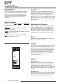
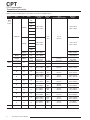
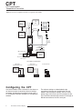
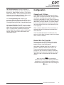
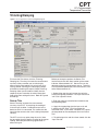
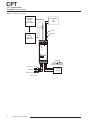
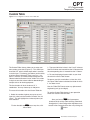
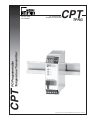
CPT
PC-Programmable
Temperature Transmitter
TPRG
CPT
PC-Programmable
Temperature Transmitter
January 2010
225-708-01D
All product names are registered trademarks of their respective companies.
Table of Contents
Introduction ............................................................................................................................................. 4
About this Manual ............................................................................................................ 4
The CPT ........................................................................................................................... 4
Model and Serial Numbers............................................................................................... 4
Inputs ............................................................................................................................... 4
Outputs............................................................................................................................. 4
Options ............................................................................................................................. 4
Specifications ................................................................................................. 5
Dimensions ...................................................................................................................... 7
Configuring the CPT....................................................................................... 8
Installing the Configuration Software ............................................................................... 9
Connecting the CPT to the PC ........................................................................................ 9
PC Configuration Software Summary ........................................................ 10
Configuration ................................................................................................ 11
Output Level if Failure .................................................................................................... 11
Broken Wire Test Override ............................................................................................. 11
Alarms ............................................................................................................................ 12
Trimming/Damping ....................................................................................... 13
Sensor Trim .................................................................................................................... 13
Output Trim ..................................................................................................................... 15
Loop Test ........................................................................................................................ 15
Output Damping ............................................................................................................. 16
Output Measurement if OFF .......................................................................................... 16
Custom Table ................................................................................................ 17
Installation..................................................................................................... 18
Mounting the CPT .......................................................................................................... 18
Making the Electrical Connections ................................................................................. 18
Recommended Ground Wiring Practices ....................................................................... 18
CE Conformity ................................................................................................................ 18
Operation....................................................................................................... 18
Maintenance................................................................................................................... 18
Customer Support ........................................................................................ 18
CPT
PC-Programmable
Temperature Transmitter
The CPT
Introduction
This is the user’s manual for the Moore Industries
CPT PC-Programmable Temperature Transmitter
(TPRG:RTD, T/C, Ohms, mV and Potentiometer
inputs). It contains all of the information needed
to configure, install, operate, and maintain this
instrument.
The CPT (TPRG) is a PC-Programmable, userconfigurable, temperature transmitter. The instrument
includes an analog output and an optional alarm
(relay) output. The alarm can be configured as a trip
or fault alarm. The CPT has a READY LED to indicate
the health of the unit, an INPUT LED to indicate the
status of the input and a dual color LED to indicate
alarm status.
About this Manual
Wherever you see a “Note”, “Caution”, or “WARNING
” pay particular attention.
WARNING - Hazardous procedure or condition that
could injure the operator.
Caution - Hazardous procedure or condition that could
damage or destroy the unit.
Note - Information that is helpful for a procedure,
condition or operation of the unit.
Model and Serial Numbers
Moore Industries uses a system of model and serial
numbers to keep track of all of the information on
every unit it sells and services. If a problem occurs
with your CPT, check for a tag affixed to the unit
listing these numbers. Supply the Customer Support
representative with this information when calling.
Inputs
Refer to Table 3 of this manual for input ranges and
accuracies of the CPT (TPRG).
Figure 1. The CPT (TPRG)
Outputs
COMPUTER
PROGRAMMABLE
TRANSMITTER
INPUT
READY
The CPT has a factory configurable current or voltage
output. The curent output range is 0-20mA. The
voltage output is 0-10V. An Analog Output (-AO) is
standard. The current output is factory configurable
as sink or source. Please notify Moore Industries
of your required configuration. The output may
also be configured to narrower spans from the PC
Configuration Program.
ALARM
Options
COM
Relay Output (-C)
An optional Relay Output (-C) is available. This is a
one relay output with a 5A@250Vac or 5A@24Vdc,
50/60Hz non-inductive contact rating. The relay
contact arrangement is SPDT. All relay contacts (NO,
NC and COM) are available for use. No jumpers are
required.
RF Option (-RF)
An RF option is also available. This version provides
30V/m RFI/EMI immunity compared to our standard
model which offers 10V/m RFI/EMI immunity.
4
The Interface Solution Experts
CPT
PC-Programmable
Temperature Transmitter
Specifications
Performance Maximum Load
(continued) Resistance: 1 kohm
Line Voltage Effect:
±0.002% of span per 1%
change in line voltage
(AC or DC)
Isolation: STANDARD
UNIT: 1000Vrms between
case, input and output.
1500Vrms between power
and input and between
power and output; WITH
-RF OPTION: 500Vrms
between case, input,
output and power
Power Consumption:
2.5W typical, 3W maximum
Power Supply Effect:
±0.002% of span per 1% of
line change
Input Impedance:
T/C and mV inputs,
40 Mohms, nominal
Input Over-Range
Protection: ±5Vdc
Excitation Current (RTD
and Ohm Inputs Only):
250 microamps, ±10%
Performance Input Accuracy:
See Table 3
Output Accuracy: Current,
±0.01% of maximum span
(±2 microamps)
Voltage, ±0.01% of
maximum span (±1mV)
Overall Accuracy: The
overall accuracy of the unit
is the combined input and
output (if any) accuracies.
It includes the combined
effects of linearity,
hysteresis, repeatability,
and adjustment resolution.
It does not include ambient
temperature effect
Mimimum Span at
Specified Accuracy:
See Table 3
Reference Junction
Compensation Accuracy
(T/C Inputs Only): ±0.45°C
Stability: See Table 1
Response Time: 256msec
maximum
(128msec typical) for the
output to change from 10
to 90% of its scale for an
input step change of 0 to
100%
Ripple: Voltage output,
50mVp-p maximum; Current
output, 10mVp-p measured
across a 250 ohm load
resistor. (Frequencies up to
120Hz)
Output Limiting:
Input over range, -0.2V/0mA
and 10.5V/21.4mA; Input
failure, -0.5V/0mA and
11V/24mA
Output Current Limiting:
25mA maximum
Load Effect: 0.01% of
span from 0 to maximum
load resistance on current
output
Performance
with Alarm
Trip
(-C Option)
WITH ALARM TRIP
OUTPUT:
Alarm Trip Repeatability:
See Table 3
Response Time:
300msec (Defined as time
from step change on input
to alarm state change
when alarm is set to trip
midpoint)
Alarm Deadband:
Programmable from
0-100% of input range
Alarm Trip Delay:
0-120 seconds
Indicators LED Type: INPUT LED:
Dual color LED indicates
input failure
READY LED: Green LED
indicates unit is operating
properly
ALARM 1 LED: Dual color
LED indicates alarm status
Ambient Operating & Storage
Conditions Range: -40°C to +85°C
(-40°F to +185°F)
Relay Range: -25°C to
+70°C (-13°F to +158°F)
Effect of Ambient
Temperature on
Reference Junction
Compensation (T/C
Inputs Only): ±0.005°C
per °C change of ambient
temperature
Relative Humidity:
0-95% non-condensing
Ambient Temperature
Effect: ±0.015% of
maximum span/°C
RFI/EMI Immunity
STANDARD UNIT:
10V/m@20-1000MHz, 1kHz
when tested according to
IEC1000-4-3-1995 with
0.5% of span or less error
WITH -RF OPTION:
30V/m@20-1000MHz, 1kHz
AM when tested according
to IEC1000-4-3-1995 with
0.5% of span or less error
Noise Rejection: Common
mode,
100dB@50/60Hz;
Normal Mode,
See Table 2
Weight 535 g (17.2 oz)
Specifications and information subject to change without notice.
Table 2. Normal Mode Rejection Ratio Table
Table 1. Long-Term Stability
Input-to-Analog
Output (Years)
Input-to-Relay
Output (Years)
Stability
(% of maximum
span)
1
3
5
1
RTD, Ohm, & Pot Inputs
0.066
0.114
0.147
0.47
0.081 0.104
T/C & mV Inputs
0.047
0.082
0.106
0.008
0.014 0.019
3
5
Sensor Type
T/C: J, K, N, C, E
T/C: T, R, S, B
Pt RTD: 100, 200, 300 ohms
Pt RTD: 400, 500, 1000 ohms
Ni: 120 ohms
Cu: 9.03 ohms
Resistance
mV
1-4 kohms
250-1000
0.25-1 kohms
62.5-250
0.125-0.25 kohms
31.25-62.5
Max. p-p Voltage Injection for
100dB at 50/60Hz
150mV
80mV
250mV
1V
500mV
100mV
1V
250mV
100mV
The Interface Solution Experts
5
CPT
PC-Programmable
Temperature Transmitter
Table 3. Accuracy with RTD, Thermocouple, Ohms, Potentiometer and Millivolt Inputs
Input
Type
α
Ohms
RTD
(2-, 3-,
4-Wire)
Conformance
Range
Minimum
Span
Input
Accuracy/Repeatability
Maximum
Range
100
200
300
0.003850
400
-240 to 960°C
-400 to 1760°F
-200 to 850°C
-328 to 1562°F
500
1000
Platinum
10°C
(18°F)
100
±0.1°C
(±0.18°F)
200
0.003902
400
-100 to 650°C
-148 to 1202°F
-150 to 720°C
-238 to 1328°F
-200 to 510°C
-328 to 950°F
-80 to 320°C
-112 to 608°F
-50 to 250°C
-58 to 482°F
±0.85°C
(±1.53°F)
-240 to 580°C
-400 to 1076°F
-100 to 360°C
-148 to 680°F
-65 to 280°C
-85 to 536°F
500
1000
0.003916
100
Nickel
0.00672
120
Copper
0.00427
9.035
Direct Resistance
Ohms
Potentiometer
T/C
mV
6
0-4000
0-4000 ohms
10 ohms
±0.4 ohms
0-4000 ohms
4000 max.
0-100%
10%
±0.1%
0-100%
n/a
J
n/a
n/a
-180 to 760°C
-292 to 1400°F
35°C
63°F
±0.25°C
(±0.45°F)
-210 to 770°C
-346 to 1418°F
K
n/a
n/a
-150 to 1370°C
-238 to 2498°F
40°C
72°F
±0.3°C
(±0.54°F)
-270 to 1390°C
-454 to 2534°F
E
n/a
n/a
-170 to 1000°C
-274 to 1832°F
35°C
63°F
±0.2°C
(±0.36°F)
-270 to 1013°C
-454 to 1855.4°F
T
n/a
n/a
-170 to 400°C
-274 to 752°F
35°C
63°F
±0.25°C
(±0.45°F)
-270 to 407°C
-454 to 764.6°F
R
n/a
n/a
0 to 1760°C
32 to 3200°F
50°C
90°F
±0.55°C
(±0.99°F)
-50 to 1786°C
-58 to 3246.8°F
S
n/a
n/a
0 to 1760°C
32 to 3200°F
50°C
90°F
±0.55°C
(±0.99°F)
-50 to 1786°C
-58 to 3246.8°F
B
n/a
n/a
400 to 1820°C
752 to 3308°F
75°C
135°F
±0.75°C
(±1.35°F)
200 to 1836°C
392 to 3336.8°F
N
n/a
n/a
-130 to 1300°C
-202 to 2372°F
45°C
81°F
±0.4°C
(±0.72°F)
-270 to 1316°C
-454 to 2400.8°F
C
n/a
n/a
0 to 2300°C
32 to 4172°F
100°C
180°F
±0.8°C
(±1.44°F)
0 to 2338°C
32 to 4240.4°F
DC
n/a
n/a
-50 to 1000mV
4mV
±15 microvolts
-50 to 1000mV
The Interface Solution Experts
CPT
PC-Programmable
Temperature Transmitter
Figure 2. CPT (TPRG) Dimensions
WHEN INSTALLED
136mm
(5.36 in)
131mm
(5.16 in)
WHEN INSTALLED
124mm
(4.89 in)
35mm
(1.38 in)
COMPUTER
PROGRAMMABLE
TRANSMITTER
53mm
(2.09 in)
INPUT
READY
ALARM
100mm
(3.94 in)
CL
COM
48mm
(1.89 in)
Table 4. Terminal Designations
Top Terminals (Left to Right)
Input Type
T1
T2
RTD, Ohm, Potentiometer,
T/C & mV Inputs
T3
T4
See Figure 3
T5
T6
+OUT
–OUT
Bottom Terminals (Left to Right)
Power/Options
B1
B2
B3
B4
B5
B6
Standard Unit
Not
Used
Not
Used
Not
Used
AC/DC
ACC/DCC
GND
With Alarm Trip (-C) Option
NO
CM
NC
AC/DC
ACC/DCC
GND
NOTES:
1. Terminal blocks can accomodate 14-22 AWG
solid wiring.
2. NO/CM/NC labeling is present only when the
unit is equipped with the Alarm Trip (-C) option.
KEY:
AC/DC = Power Input
ACC/DCC = Power Input
CM = Relay Common
COM = Analog Common
GND = Ground
OUT = Current Output
NO = Normally Open
NC = Normally Closed
SPDT = Single-Pole/Double-Throw
Figure 3. Temperature Sensor Hook-Up Guide
Thermocouple
and Millivolt
Input
+
1 2 3 4
2-Wire RTD
or Decade
Resistance Box
3-Wire RTD
or Decade
Resistance Box
4-Wire RTD
or Decade
Resistance Box
Potentiometer
Input
1 2 3 4
1 2 3 4
1 2 3 4
1 2 3 4
–
The Interface Solution Experts
7
CPT
PC-Programmable
Temperature Transmitter
Figure 4. Use the PC Configuration Software to program the CPT (TPRG)
MULTIMETER
OR
+
– DCS
MILLIVOLT _
SOURCE
OR T/C +
SIMULATOR
A +OUT
A -OUT
PC
OHMS OR
2-WIRE
RTD
SIMULATOR
TO SERIAL
(COM) PORT
OF PC
INPUT
READY
To USB
(COM)
Port of PC
(optional)
ALARM
COM
24VDC OR
117VAC OR 230VAC
COMMON
NC
NO (normally open)
COM
NO
(CHECK MODEL NUMBER
FOR UNIT CONFIGURATION)
GND
– POWER
+ SOURCE
NC (normally closed)
With -C option
INPUT HOOK-UP CONNECTIONS
3-Wire RTD or
Decade Resistance Input
4-Wire RTD or
Decade Resistance Input
OHMS
OR RTD
SIMULATOR
OHMS
OR RTD
SIMULATOR
Potentiometer Input
Configuring the CPT
One of the benefits of this transmitter is that there are
no internal or external controls to adjust or settings
to change. All operating parameters are set using a
PC and Moore Industries’ Intelligent PC Configuration
software.
8
The Interface Solution Experts
The software settings are downloaded to the
transmitter in the form of a Configuration File and
stored in the instrument’s memory. You can save a
backup copy of the file on your PC hard drive or disk.
The transmitter communicates with the PC through an
RS-232 connection to the PC’s serial port.
CPT
PC-Programmable
Temperature Transmitter
Installing the Configuration Software
Refer to Table 5 for the equipment needed.
1.
Insert the Moore Industries Interface Solution
PC Configuration Software CD into the CD
drive of the PC. Access the CD and open the
“CPA CPT PC Configuration Software” folder.
2.
Double-click the installation program located
in the folder. Follow the prompts to correctly
install the program.
Once the Configuration Program is installed on the
PC, the CPT can be connected to equipment to
simulate input and monitor output. You can then
change the transmitter’s operating parameters.
The CPT must be connected to the PC in order to:
trim input, trim output, assign a tag, perform a loop
test, receive (via download) a configuration file, and
save the configuration file from the transmitter’s
memory.
Connecting the CPT to the PC
Connect the RS-232 end of the cable to the PC’s COM
port.
See Table 5 for information on the necessary
equipment.
No Transmitter Needed
It is not necessary to connect the transmitter to a PC
to create configuration files using the software. The
Configuration Program can be run without connecting
a transmitter, and most parameters can be set without
benefit of input from a sensor or CPT.
This makes it easy to create a set of operating
parameters, save and then download them to one or
more transmitters at a later time.
Table 5. Assembling the equipment needed to configure the CPT (TPRG)
Device
Specifications
Variable Input Simulator for Thermocouple,
RTD, Millivolt, Potentiometer, or Decade Variable; Accurate to ±0.05% of unit span
Resistance Box
Power Supply 24Vdc, ±10% or 117/230Vac (depending on configuration)
Multimeter (optional)
Accurate to ±0.009% of span; e.g., HP Model 3478A
80386-based(or faster) IBM PC, or 100% compatible;
4Mb free RAM; 8Mb recommended; 20Mb free disk space on hard drive
(More RAM & hard disk space is required for Windows NT, 2000, XP, Vista, or 7)
Personal Computer Microsoft Windows® NT, 2000, XP, Vista, or 7
Internet Explorer 3.0+
1 (one) serial port (COM 1, 2, 3, or 4) set to 9600 baud, no parity, 8 data bits,
and 1 stop bit or one available USB port (with optional USB cable)
Moore Industries PC
Version 1.0 or greater, successfully installed to the hard drive
Configuration Software
Communication Cable
Part# 803-053-26 or optional USB cable, Part# 208-236-00A
or USB Cable (Optional)
The Interface Solution Experts
9
CPT
PC-Programmable
Temperature Transmitter
PC Configuration Software Summary
Figure 5. Main PC Screen of CPT (TPRG) PC Configuration Software Program
4
5
1
12
11
7
10
2
8
3
6
9
Once the default configuration has been saved to
disk, it is safe to program other parameters. The PC
Software is made up of these sections:
1. Status– This portion of the program displays the
activity of the connected unit. It will show the COM
Port being used and the current Measurement Mode.
2. Measurements– Measurements– Displays current
software processes and indications. Allows you to
select the decimal place of your process variable
(Decimal Places (PV)) indication and monitor up to
two configuration variables (Monitored Vars).
3. Device Information– This “read only” display
indicates firmware version, hardware revision, serial
number, calibration date, software version and
configuration date and the last configuration source.
4. Communication– From here you may enable Start
Measurements and Stop Measurements, upload your
configuration to PC or download your configuration to
the unit, save your configuration to a file, and print out
your configuration settings.
10
The Interface Solution Experts
5. Input Configuration– Select 50/60Hz Rejection
Selection and selection of °C or °F. Allows you to
choose sensor type and wiring connections. You may
also enable Input Trim, Output Trim, Custom Table and
Broken Wire Test functions.
6. Device Configuration– Use this parameter to
place an identifying “Message” (32 alphanumeric
characters maximum), select an “I.D. Tag” (8
alphanumeric characters maximum) and “Descriptor”
(16 alphanumeric characters maximum).
7. Output Configuration– Use this section to select
your output configuration and output limits.
8. Output Level if Failure– Used to select
configuration of Upscale/Downscale Drive failure
detection of sensor or sensor wiring. Refer to Output
Level if
Failure section for a complete description.
9. Broken Wire Test Override– Allows you to enable
or disable the Broken Wire Test Override feature by
clicking the “BW ON” or “BW OFF” buttons. Refer to
the Broken Wire Test Override section for a complete
description.
CPT
PC-Programmable
Temperature Transmitter
10. Alarm Parameters– Use this to choose an
alarm mode and configure as either a Trip, Fault or
Band alarm. Select whether to use as a Fail Safe or
NON Fail Safe Alarm. You may also choose a Delay
(0-120sec) and a Deadband (0-100%). Refer to the
Alarms section for a complete description.
11. Trimming/Damping Tab– Selecting this
parameter allows you to perform Sensor Trim, Output
Trim and Output Damping functions. Refer to the
Trimming/Damping section for a complete description.
12. Custom Table Tab– The CPT has two modes of
operation: linear mode and custom mode. In linear
mode, the scaled output is proportional to the scaled
input. In custom mode, reached by selecting the
Custom Table Tab, you define a special linearization
function. Refer to the Custom Table section for a
complete description.
Configuration
Output Level if Failure
In the Output Level if Failure section you will notice
Down Scale and Up Scale selection. Using its output,
the CPA can be configured to provide a special
warning of a breakdown or failure. Use this setting to
configure the instrument to drive its output either up or
down when a failure is detected. For current outputs,
limits are 3.6mA (downscale) and 23.6mA (upscale);
for voltage outputs, limits are -0.5V (downscale) and
11.0V (upscale).
When a failure is detected, the “Fail Last” feature, if
enabled, holds the last measured value before the
failure occurred.
If the “User Selected” feature is enabled, you may
enter any value, within the range, to view at the output
when a failure is detected.
Broken Wire Test Override
During operation, the CPT (TPRG) sends random
microamp pulses through input wiring to check for
broken wiring or a burned out sensor.
Upon power-up Broken Wire Test is enabled. If a
problem is detected, “Broken Wire” Failure in the
Process Information section of the configuration
program will light to indicate a problem. The Broken
Wire Test may be temporarily disabled by clicking the
“BW OFF” button in the Broken Wire Test Override
section.
Note:
Once you have configured all parameters,
download to the unit by either selecting “Download
Configuration” in the Configuration dropdown menu
located in the Communications bar or by clicking the
button.
The Interface Solution Experts
11
CPT
PC-Programmable
Temperature Transmitter
Alarms
Figure 6. Band Alarm Parameter Graph
Trip Low and Trip High Alarms
In the Alarm Parameters portion of our CPT
Configuration Program you may choose a “Trip Low”
and “Trip High” limit. In choosing your limits you are
setting the parameters for your unit to notify you if your
process input drops below (Trip Low) or exceeds (Trip
High) your trip point setting.
Deadband
Fail Safe/NON Fail Safe Alarms
The Band Alarm is activated when the Process
Variable is outside of the Low/High Trip point ranges.
The Trip Low is always lower than the Trip High and
their deadbands are inside the range of Low/High
Trip. The span between the Low and High Trip is not
limited, which allows control of measurements in a
very narrow range.
A Fail Safe alarm, if in the alarm condition, will remain
in the alarm condition even if power to the unit is
removed.
Fault Alarm
Deadband (0-100%) is the range within which an alarm
relay remains in an alarm condition even after the
monitored process variable input has returned to a safe
level, at or below/above the trip point setting.
Fail Safe alarm trip relays are energized whenever the
process input is in a non-alarm condition (including
any deadband setting). These relays de-energize
when the process input trips the alarm.
NON Fail Safe alarm trip relays are energized
whenever the process input is in an alarm condition.
These relays de-energize when the process input
returns to the reset point (including any deadband).
Band Alarm
The Band Alarm incorporates Low and High Trip
points, Deadband and Delay (0-120sec).
The Band Alarm combines two Trip Alarm settings.
The first alarm is always configured as Low Trip
(Trip Point Low) and the second as High Trip (Trip
Point High). See Figure 6 for information on alarm
parameters.
12
The Interface Solution Experts
To simply be alerted in the case of any fault that may
arise, select the “Fault Alarm” button. This requires no
parameters to be set and will notify you anytime a fault
is sensed.
Note:
Once you have configured all parameters,
download to the unit by either selecting “Download
Configuration” in the Configuration dropdown menu
located in the Communications bar or by clicking the
button.
CPT
PC-Programmable
Temperature Transmitter
Trimming/Damping
Figure 7. PC Configuration Software Trimming/Damping Tab
To access the Trim feature, click the Trimming/
Damping tab . Trimming increases the measurement
accuracy of the parameter you are trimming by
either matching the reading of its actual input to its
scaling (Sensor Trimming) or calibrating the output
to the device receiving the output (Output Trimming).
Damping allows you to introduce a delay into the
response of your transmitter in order to stop shortlived spikes from setting off alarms. Refer to Figure 8
for hook-up.
Before you attempt to perform the Sensor Trim
function ensure that the Status section of the screen
indicates “Measurements On”. Sensor Trim can be
done only when the measurements are on. To do this
click the Mode dropdown box, from the menu bar, and
select “Measurements On”.
Sensor Trim
2. Enter the values that need to be trimmed into the
corresponding fields.
Sensor Trimming increases the measurement
accuracy of your CPT by matching the reading of
its actual input to either a calibrated source or the
device to which it is connected. This verifies that the
input from the sensor to the alarm is being interpreted
correctly.
The CPT can trim any point along the scale. Note
that one-point trimming applies an offset to the sensor
reading, while two-point trimming applies both an
offset and a gain.
1. Select either one trim point or two trim points by
clicking the appropriate button. Each pair consists of
“trim” and “captured” values.
3. Apply the targeted signal to the input, wait until
it settles and click “Point 1 Trim” to capture the
measured value. If you chose “Two-point Trim” repeat
the step above for the second point and click “Point 2
Trim”.
4. To enable input trim and the values stored, click the
“Input Trim ON”.
The Interface Solution Experts
13
CPT
PC-Programmable
Temperature Transmitter
Figure 8. Trimming the CPT (TPRG)
MILLIVOLT _
SOURCE
OR T/C
+
SIMULATOR
+
–
MULTIMETER
OR
DCS
A +OUT
A -OUT
OHMS
OR RTD
SIMULATOR
INPUT
READY
ALARM
COM
24VDC OR
117VAC OR 230VAC
COMMON
NC (normally closed)
With -C option
14
The Interface Solution Experts
NC
NO (normally open)
COM
NO
(CHECK MODEL NUMBER
FOR UNIT CONFIGURATION)
GND
– POWER
+ SOURCE
CPT
PC-Programmable
Temperature Transmitter
Output Trim
Loop Test
Output Trimming increases the measurement accuracy
of your CPT by calibrating its output to the device
that is receiving the output. This ensures that the
instrument is being correctly interpreted.
A Loop Test may be performed in order to check
output performance and accuracy and to trim other
instruments in the loop. Your output will be a current
value, in mA, or a voltage equal to the value you input.
You can check the other current devices on the loop
and calibrate them to this signal.
Before you attempt to perform the Output Trim
function ensure that the Status section of the screen
indicates “Measurements Off”. To do this click the
Mode dropdown box, from the menu bar, and select
“Measurements Off”.
This feature is independent of the input. If you find
that the output requires adjustment you may perform
the Output Trim function.
1. Review your Model Number label to determine if
your unit is built for Current (0-20mA) or Voltage (010V) output.
1. To use the Loop Test function select the Mode
dropdown box in the Communications bar and select
“Measurements Off”.
2. Attach a multimeter to the analog output and select
the “4mA” or “0V” button (whichever is appropriate).
Use the scroll bar to trim the measured output to your
desired value.
2. Next, in the “Output Value %” box, type the
percentage of the output value you wish to test. You
may also use your mouse, left click and adjust the
scroll bar to adjust to your desired value. Hit “Enter”.
3. With the multimeter still connected select the
“20mA” or “10V” button (whichever is appropriate).
Use the scroll bar to trim the measured output to your
desired value.
3. In the “Output Value” box enter the value, within
your configuration range, that you wish to signify as
your output value. Hit “Enter”.
4. Perform your test and calibration.
4. To enable Output Trim and the values stored, click
the “Output Trim ON” box.
5. Set Status back to “Measurements On”.
5. When you are finished, return to Mode in the
Communications bar and reset your status to
“Measurements On”.
If selected, the User trim values will be used and the
manufacturer settings will be nullified.
The Interface Solution Experts
15
CPT
PC-Programmable
Temperature Transmitter
Output Damping
Output Damping allows you to introduce a delay into
the response of your unit in order to stop short-lived
spikes from setting off alarms. Output Damping is
activated when the value set in the “Output Step
Threshold” field is exceeded.
1. To enable output damping, select the “Enabled”
button. If you do not wish to use the damping feature,
then select “Disabled”.
A possible source for the occurence above is a
rapid change on the input. Another possiblity would
be an existing output level of 5.6mA upon Start
Measurements from a PC.
Figure 10 gives another damping example where the
output has been driven upscale to 23.6mA. After
five seconds the 63% output change is reached at
16.98mA.
Figure 10. Damping When Output Driven Upscale to 23.6mA
2. Insert a value between 1 and 16mA in the “Output
Step Threshold” field. This is how much of an output
step change is allowed in a specified time frame
before flagging the software.
3. Insert a value between 0.5 and 120sec in the
“Damping Sec” field. This is the amount of time it will
take for the output to reach 63% of the step output
change once the input exceeds the value in the
“Output Step Threshold” field.
By checking the appropriate box in the Other Damping
Options section, you may also choose to select Output
Damping to occur upon power up or start up from
a PC, upon broken wire failure detection or upon
resolution of broken wire failure.
A typical damping situation would be described as a
step change in output which causes the output to go
from 5.6mA to 20mA. After five seconds the output
reaches 14.58mA which equals 63% of the output step
change. This is graphed in Figure 9.
In this case, an instrument malfunction or
Adc/EEPROM failure may be to blame.
Output if Measurement OFF
Choose “Zero Range” to read zero volts or mA at
output if measurement was off.
Choose “Stay Last” to read the last value held before
the measurement was off.
Figure 9. Typical Damping Scenario
Note:
Once you have configured all parameters,
download to the unit by either selecting “Download
Configuration” in the Configuration dropdown menu
located in the Communications bar or by clicking the
button.
16
The Interface Solution Experts
CPT
PC-Programmable
Temperature Transmitter
Custom Table
Figure 11. PC Configuration Software Custom Table Tab
The Custom Table feature allows you to setup your
own custom curve table (Figure 11). This allows you
to tell the CPT what it should output when it receives
a certain input. This feature also allows you the ability
to write a table in Microsoft® Excel, save it in a .csv
format. The files are saved to/read to/read from the
“Moore Industries\Custom Curves” folder. This makes
it simple to save the custom table for downloading to
multiple units or for backup purposes.
The linearization will be in the form of X, Y
coordinates. You may choose up to 128 points.
To access this function click the Custom Table tab.
1. Select the number of points you are to set and
insert this value into the “Number Of Points” line, hit
“Enter”. This will highlight the number of points you
have selected.
Note:
To clear the table and start over at any time, click
“Clear Table”.
2. Type your individual values in the X and Y columns.
Source variables are inserted into the X Column while
the corresponding data is inserted into the Y Column.
3. To save the displayed custom table to your hard
drive click the “Save Table” button.
To open or use this saved table at a later time, click
the “Open Table” button and select the folder in which
it has been saved.
Use the “Table EGU” box to enter any alphanumeric
engineering unit (up to 6 digits).
To use the Custom Table feature in your operation
check the “Custom Table ON” box.
Note:
Once you have configured all parameters,
download to the unit by either selecting “Download
Configuration” in the Configuration dropdown menu
located in the Communications bar or by clicking the
button.
The Interface Solution Experts
17
CPT
PC-Programmable
Temperature Transmitter
Installation
Operation
Installation consists of physically mounting the unit
and completing the electrical connections.
Once programmed, calibrated, installed, and supplied
with the correct power, the CPT transmitter begins to
operate immediately. Depending upon environmental
conditions, it can be expected to operate unattended
for extended periods of time.
Mounting the CPT
The CPT can be mounted on standard DIN mounting
rails.
Maintenance
Making the Electrical Connections
Please refer to Figure 4 for electrical connections.
Recommended Ground Wiring
Practices
Moore Industries recommends the following ground
wiring practices:
• Any Moore Industries product in a metal case or
housing should be grounded.
• The protective earth conductor must be connected
to a system safety earth ground before making any
other connections.
• All input signals to, and output signals from, Moore
Industries’ products should be wired using a
shielded, twisted pair technique. Shields are to be
connected to an earth or safety ground at the unit
itself.
• The maximum length of unshielded input
and/or output signal wiring should be
two inches.
CE Conformity
Installation of any Moore Industries’ products that
carry the CE certification must adhere to the
guidelines above in order to meet the requirements set
forth in the European EMC and Low Voltage Directives
(EN 61326 and EN 61010). Consult the factory for the
most current information on products that have been
CE certified.
18
The Interface Solution Experts
Moore Industries suggests a check for terminal
tightness and general unit condition every 6-8
months. Always adhere to any site requirements for
programmed maintenance.
Customer Support
Moore Industries is recognized as the industry leader
in delivering top quality to its customers in products
and services. We perform a battery of stringent quality
assurance checks on every unit we ship. If any Moore
Industries product fails to perform up to rated specifications, call us for help. Our highly skilled staff of
trained technicians and engineers pride themselves on
their ability to provide timely, accurate, and practical
answers to your process instrumentation questions.
Factory phone numbers are listed on the back cover of
this manual.
If problems involve a particular CPT, there are several
pieces of information that can be gathered before
you call the factory that will help our staff get the answers you need in the shortest time possible. For
the fastest service, gather the complete model and
serial number(s) of the problem unit(s) and the job
number of the original sale.
Declaration of Conformity
EMC Directive 89/336/EEC
• Manufacturer’s Name:
• Manufacturer’s Address:
Moore Industries-International, Inc.
16650 Schoenborn Street
North Hills, CA 91343-6196
USA
Declares that the product(s):
• Product Name:
CPT
MODEL /
• Model Number(s):
CPT
INPUT
/
OUTPUT
*
*
/
POWER
/
*
OPTIONS
/
*
HOUSING
*
* Indicates any input, output, power, option and housing as listed on the product data sheet
• Conforms to the following EMC specifications:
EN 61326-1, 1998, Electromagnetic Compliance (EMC) requirements for electrical equipment for control use
EN 61010-1, 1995, Safety requirements for electrical equipment for measurement and control use
• Supplementary Information:
None
25 March 2003
Date
Fred Adt
Quality Assurance Director
Robert Stockham
Moore Industries-Europe General Mgr.
European Contact: Your Local Moore Industries Sales and Service Office
United States • [email protected]
Tel: (818) 894-7111 • FAX: (818) 891-2816
Australia • [email protected]
Tel: (02) 8536-7200 • FAX: (02) 9525-7296
Belgium • [email protected]
Tel: 03/448.10.18 • FAX: 03/440.17.97
The Netherlands • [email protected]
Tel: (0)344-617971 • FAX: (0)344-615920
China • [email protected]
Tel: 86-21-62491499 • FAX: 86-21-62490635
United Kingdom • [email protected]
Tel: 01293 514488 • FAX: 01293 536852
RETURN PROCEDURES
To return equipment to Moore Industries for repair, follow these four steps:
1. Call Moore Industries and request a Returned Material Authorization (RMA) number.
Warranty Repair –
If you are unsure if your unit is still under warranty, we can use the unit’s serial number
to verify the warranty status for you over the phone. Be sure to include the RMA
number on all documentation.
Non-Warranty Repair –
If your unit is out of warranty, be prepared to give us a Purchase Order number when
you call. In most cases, we will be able to quote you the repair costs at that time.
The repair price you are quoted will be a “Not To Exceed” price, which means that the
actual repair costs may be less than the quote. Be sure to include the RMA number on
all documentation.
2. Provide us with the following documentation:
a) A note listing the symptoms that indicate the unit needs repair
b) Complete shipping information for return of the equipment after repair
c) The name and phone number of the person to contact if questions arise at the factory
3. Use sufficient packing material and carefully pack the equipment in a sturdy shipping container.
4. Ship the equipment to the Moore Industries location nearest you.
The returned equipment will be inspected and tested at the factory. A Moore Industries representative will contact the person designated on your documentation if more information is
needed. The repaired equipment, or its replacement, will be returned to you in accordance
with the shipping instructions furnished in your documentation.
WARRANTY DISCLAIMER
THE COMPANY MAKES NO EXPRESS, IMPLIED OR STATUTORY WARRANTIES (INCLUDING ANY WARRANTY OF MERCHANTABILITY OR
OF FITNESS FOR A PARTICULAR PURPOSE) WITH RESPECT TO ANY
GOODS OR SERVICES SOLD BY THE COMPANY. THE COMPANY DISCLAIMS ALL WARRANTIES ARISING FROM ANY COURSE OF DEALING
OR TRADE USAGE, AND ANY BUYER OF GOODS OR SERVICES FROM
THE COMPANY ACKNOWLEDGES THAT THERE ARE NO WARRANTIES
IMPLIED BY CUSTOM OR USAGE IN THE TRADE OF THE BUYER AND
OF THE COMPANY, AND THAT ANY PRIOR DEALINGS OF THE BUYER
WITH THE COMPANY DO NOT IMPLY THAT THE COMPANY WARRANTS
THE GOODS OR SERVICES IN ANY WAY.
ANY BUYER OF GOODS OR SERVICES FROM THE COMPANY
AGREES WITH THE COMPANY THAT THE SOLE AND EXCLUSIVE REMEDIES FOR BREACH OF ANY WARRANTY CONCERNING THE GOODS OR
SERVICES SHALL BE FOR THE COMPANY, AT ITS OPTION, TO REPAIR
OR REPLACE THE GOODS OR SERVICES OR REFUND THE PURCHASE
PRICE. THE COMPANY SHALL IN NO EVENT BE LIABLE FOR ANY CONSEQUENTIAL OR INCIDENTAL DAMAGES EVEN IF THE COMPANY FAILS
IN ANY ATTEMPT TO REMEDY DEFECTS IN THE GOODS OR SERVICES
, BUT IN SUCH CASE THE BUYER SHALL BE ENTITLED TO NO MORE
THAN A REFUND OF ALL MONIES PAID TO THE COMPANY BY THE BUYER
FOR PURCHASE OF THE GOODS OR SERVICES.
ANY CAUSE OF ACTION FOR BREACH OF ANY WARRANTY BY
THE COMPANY SHALL BE BARRED UNLESS THE COMPANY RECEIVES FROM THE BUYER A WRITTEN NOTICE OF THE ALLEGED
DEFECT OR BREACH WITHIN TEN DAYS FROM THE EARLIEST DATE
ON WHICH THE BUYER COULD REASONABLY HAVE DISCOVERED
THE ALLEGED DEFECT OR BREACH, AND NO ACTION FOR THE
BREACH OF ANY WARRANTY SHALL BE COMMENCED BY THE
BUYER ANY LATER THAN TWELVE MONTHS FROM THE EARLIEST
DATE ON WHICH THE BUYER COULD REASONABLY HAVE DISCOVERED THE ALLEGED DEFECT OR BREACH.
RETURN POLICY
For a period of thirty-six (36) months from the date of shipment, and under
normal conditions of use and service, Moore Industries (“The Company”)
will at its option replace, repair or refund the purchase price for any of its
manufactured products found, upon return to the Company (transportation
charges prepaid and otherwise in accordance with the return procedures
established by The Company), to be defective in material or workmanship.
This policy extends to the original Buyer only and not to Buyer’s customers
or the users of Buyer’s products, unless Buyer is an engineering contractor
in which case the policy shall extend to Buyer’s immediate customer only.
This policy shall not apply if the product has been subject to alteration,
misuse, accident, neglect or improper application, installation, or operation.
THE COMPANY SHALL IN NO EVENT BE LIABLE FOR ANY INCIDENTAL
OR CONSEQUENTIAL DAMAGES.
United States • [email protected]
Tel: (818) 894-7111 • FAX: (818) 891-2816
Australia • [email protected]
Tel: (02) 8536-7200 • FAX: (02) 9525-7296
© 2004 Moore Industries-International, Inc.
Belgium • [email protected]
Tel: 03/448.10.18 • FAX: 03/440.17.97
The Netherlands • [email protected]
Tel: (0)344-617971 • FAX: (0)344-615920
China • [email protected]
Tel: 86-21-62491499 • FAX: 86-21-62490635
United Kingdom • [email protected]
Tel: 01293 514488 • FAX: 01293 536852
Specifications and Information subject to change without notice.