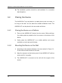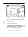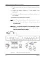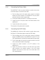
1
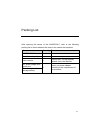
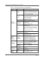
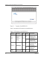
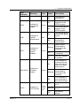
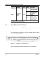
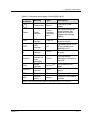
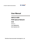
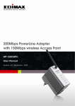
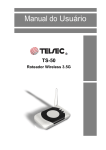
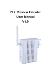
AN5506-04-F GPON Optical Network Unit User Manual Version: A Code: MN000000619 FiberHome Telecommunication Technologies Co., Ltd. June 2010 Thank you for choosing our products! We appreciate your business. Your satisfaction is our goal. We will provide you with comprehensive technical support and after-sales service. Please contact your local sales representative, service representative or distributor for any help needed at the contact information shown below. Fiberhome Telecommunication Technologies Co., Ltd. Address: No. 5 Dongxin Rd., Hongshan Dist., Wuhan, China Zip code: 430073 Tel: +86-27-87691549 Fax: +86-27-87691755 Website: http://www.fiberhomegroup.com Legal Notice TM TM TM are trademarks of FiberHome Telecommunication Technologies Co., Ltd. (Hereinafter referred to as FiberHome) All brand names and product names used in this document are used for identification purposes only and are trademarks or registered trademarks of their respective holders. All rights reserved No part of this document (including the electronic version) may be reproduced or transmitted in any form or by any means without prior written permission from FiberHome. Information in this document is subject to change without notice. Operation Safety Rules High optical power can cause bodily harm, especially to eyes. Never look directly into the end of the optical transmitter fiber jumper or the end of its active connector. Exercise care if you must bend fibers. If bends are necessary, the fiber bending radius should never be less than 38mm. Power socket overload, broken cables or broken plugs may cause electric shock or fire. Regular check-ups on power supply wires and cables are essential. If any appear damaged, replace at once. Use the power supply adapter provided in the package only. Using other adapters may cause equipment damage or operation failures. Install the equipment in a well ventilated environment without high temperatures or direct sunlight to protect the equipment and its components from overheating, which can result in damage. I Avoid moisture, dampness and water damage. Equipment exposed to water cannot work normally and can be extremely hazardous due to shorting. II Do not lay this equipment on an unsteady base. Packing List After opening the carton of the AN5506-04-F, refer to the following packing list to check whether the items in the carton are complete: Item Quantity Remarks AN5506-04-F 1 - Certificate of quality 1 - User manual 1 AN5506-04-F GPON Opitical Network Unit User Manual 1 Select one power adapter according to the requirement of the customer. AC power adapte with three pins Power adapter with storage battery III Contents 1 Product Introduction ........................................................................ 1-1 1.1 Product Functions ................................................................... 1-1 1.2 Product Type .......................................................................... 1-3 1.3 Technical Specifications .......................................................... 1-3 2 Appearance Description .................................................................. 2-1 2.1 Top Panel and LED Indicators ................................................ 2-1 2.2 Rear Panel and Interfaces ...................................................... 2-4 3 Product Installation.......................................................................... 3-1 3.1 Preparation Before Installation................................................ 3-1 3.1.1 Checking Items in the Package.................................. 3-1 3.1.2 Installation Precautions .............................................. 3-1 3.2 Placing the Device .................................................................. 3-2 3.2.1 Placing the Device on a Platform ............................... 3-2 3.2.2 Mounting the Device on the Wall................................ 3-2 3.3 Cable Connection ................................................................... 3-3 3.3.1 Connecting the Network Cable .................................. 3-3 3.3.2 Connecting the Phone Cable ..................................... 3-5 3.3.3 Connecting the CATV Cable ...................................... 3-5 3.3.4 Connecting the Fiber .................................................. 3-6 3.3.5 Connecting the Power Cable ..................................... 3-8 3.4 Checking After Installation ...................................................... 3-9 4 FAQs ............................................................................................... 4-1 Figures Figure 1-1 Network application of the AN5506-04-F ...................... 1-1 Figure 2-1 Top panel of the AN5506-04-G1 ................................... 2-2 Figure 2-2 Rear panel of the AN5506-04-G1 ................................. 2-4 Figure 3-1 Dimensions of recesses on the AN5506-04-F bottom panel ............................................................................ 3-3 Figure 3-2 Cable connection (three-pin power) .............................. 3-4 Figure 3-3 Fiber connection (1) ...................................................... 3-6 Figure 3-4 Fiber connection (2) ...................................................... 3-7 Figure 3-5 Fiber connection (3) ...................................................... 3-7 Figure 3-6 Cable connection .......................................................... 3-9 Tables Table 1-1 Product type ................................................................... 1-3 Table 1-2 Technical specifications of the AN5506-04-F .................. 1-4 Table 2-1 LED indicators of the AN5506-04-G1 ............................. 2-2 Table 2-2 Interfaces and buttons of the AN5506-04-G1 ................. 2-5 1 Product Introduction 1.1 Product Functions The AN5506-04-F is an FTTH GPON optical network unit. It provides communication and entertainment service in multiple modes such as data, voice, and video, to meet integrated access requirement of families or small enterprises. The following figure shows the network application of the AN5506-04-F: Figure 1-1 Version A Network application of the AN5506-04-F 1-1 AN5506-04-F GPON Optical Network Unit User Manual As shown in Figure 1-1, the AN5506-04-F works with the AN5116-06B (the OLT) to build a gigabit GPON system, which provides triple-play multi-service access of high capacity and reliability. The AN5506-04-F is one of the AN5506-04 series and it supports the following features: Adopts GPON interface for uplinkings, compliant with ITU-T G.984. Supports configuring the Ethernet interface rate, working mode, MDI/MDIX self-adaption mode, and pause-frame-based flow control. Provides lightningproof and ESD protection of Ethernet interfaces. Supports packet filtering and DoS attack protection, to suppress unknown unicast, broadcast, and multicast packets. Supports performance statistics of Ethernet lines. Supports reporting the physical position information of Ethernet interfaces through DHCP Option82. Supports PPPoE+ function for accurate user identification. Supports various voice protocols including H.248, MGCP, and SIP. Supports IGMP snooping and IGMP proxy. Supports the STP/RSTP protocol. Supports L2/L3 line-speed forwarding. Adopts triple churning algorithm for data encryption of downstream data in GPON system. 1-2 Version A 1 Product Introduction Supports powerful QoS function. Supports global configuration of queue priority and flexible mapping of 802.1p value of packets. Supports three scheduling modes: PQ, WRR, and PQ+WRR. You can configure the weight of scheduling queue to ensure QoS of key services such as voice and video under multiple service conditions. Supports wireless access mode, compliant with 802.11 b/g/n. Supports the following authentication modes: open, shared, WPA, WPAPSK, WPA2, WPA2PSK, WPA1WPA2, WPAPSKWPA2PSK, and 802.1x. Supports the following encryption modes: none, WEP, TKIP, AES, and TKIPAES. 1.2 Product Type The AN5506-04-F has two types: AN5506-04-F1 and AN5506-04-G1. Both types provide Ethernet interfaces, phone interfaces and WiFi access. In addition, the AN5506-04-G1 supports CATV interface. Table 1-1 lists the two product types and the interfaces that each type supports. Table 1-1 Product type Product Type 1.3 Ethernet Interface Phone Interface CATV Interface Power Interface AN5506-04-F1 4 2 - 1 AN5506-04-G1 4 2 1 Three-pin power jack Technical Specifications Table 1-2 lists technical specifications of the AN5506-04-F in detail. Version A 1-3 AN5506-04-F GPON Optical Network Unit User Manual Table 1-2 Technical specifications of the AN5506-04-F Type Item Voice Description Supports the following voice protocols: H.248, MGCP, and SIP. Adopts the following voice coding: G.711a/u, G.723, G.729. Supports IEEE 802.1Q VLAN. VLAN Supports adding 802.1Q VLAN in tag or untag mode. Supports 64 VLANs. Service parameter MAC address Supports 8k MAC addresses. Multicast Supports IGMP snooping and IGMP proxy. Supports IGMP V1/V2. Supports 802.1P. QoS Supports QoS classification based on port, MAC address, and VLAN ID. Supports priority re-tag. Network side interface User side interface Mechanical parameter Power supply 1-4 Line speed L2/3 switching All interfaces support line speed forwarding. CATV Output level: 75dBuV. Owned by the AN5506-04-G1. GPON interface G.984-compliant, the maximum transmission distance is 20 km. One SC/PC inerface for the AN5506-04-F1 and one SC/APC interface for the AN5506-04-G1. LAN interface Four RJ-45 interfaces. Supports full duplex or half duplex, 10/100 Mbps self-adaption. Phone interface Two RJ-11 interfaces. Dimension (H x W x D:) 45 mm x 190 mm x 235 mm Weight About 650 g DC Input voltage: 12 V DC Version A 1 Product Introduction Type Item Description Power consumption - 15 W Operating temperature 0˚C to 45˚C Storage temperature -30˚C to 60˚C Environment humidity 10% to 90%, non-condensing. Environment parameter Note: Technical specifications of the CATV interface are only supported by AN5506-04-G1. Version A 1-5 2 2.1 Appearance Description Top Panel and LED Indicators The AN5506-04-F adopts hollow-carved streamline design with novel and fashionable appearance. You can know the running status of the device according to the LED indicators on the top panel. The following takes the AN5506-04-G1 as an example. Figure 2-1 shows the top panel of AN5506-04-G1. Version A 2-1 AN5506-04-F GPON Optical Network Unit User Manual Figure 2-1 Top panel of the AN5506-04-G1 Table 2-1 describes the LED indicators of the AN5506-04-G1. Table 2-1 LED indicators of the AN5506-04-G1 LED Indicator VoIP Phone1/2 Power 2-2 Meaning Registration status indicator of voice service Indicator of phone status Indicator of power status Color Status Description On The device registers to the softswitch system successfully. Off The device fails to register to the softswitch system. On The user picks up the phone or the user is in a conversation. Off The phone is on hook or is not connected. On The device is powered on. Green Green Green Version A 2 LED Indicator PON LOS WIFI LAN1/2/3/4 CATV Version A Meaning Indicator of registration status Indicator of optical signal status Indicator of wireless signal statatus Indicator of Ethernet status Indicator of CATV status Color Status Description Off The device is powered off. On The device registers to the GPON system. Off The device fails to register to the GPON system. On The device fails to receive the optical signal. Off The device receives the optical signal. Blinking Data is being transmitted or received at this interface. Off The WIFI service is disabled. On The WIFI service is enabled. On This interface is connected to the user terminal but there is no data transmission. Blinking Data is being transmitted or received at this interface. Off This interface is not connected to the user terminal. On Optical power: -8 to +2 Blinking Optical power: -25 to -8 Off Indicationg others. Green Red Green Green Green (1550 nm) Appearance Description 2-3 AN5506-04-F GPON Optical Network Unit User Manual LED Indicator Note Battery Meaning Indicator of battery status Color Status Description On The battery works normally. Blinking The battery works abnormally, such as overlow voltage. Off The power adapter of the storage battery is not in use or the battery is faulty. Green Note: When the power with three pins is adopted, the Battery indicator is off and does not indicate anything. 2.2 Rear Panel and Interfaces All interfaces and buttons of AN5506-04-F are distributed on the rear panel of the device, with a compact shape and good utility. The following takes the AN5506-04-G1 as an example. Figure 2-2 shows the rear panel of AN5506-04-G1. Figure 2-2 Rear panel of the AN5506-04-G1 Table 2-2 describes the interfaces and buttons of the AN5506-04-G1: 2-4 Version A 2 Appearance Description Table 2-2 Interfaces and buttons of the AN5506-04-G1 Interface or Button Meaning Type Description Power switch Button Turn on or off the power. Power Power interface Power interface with three pins For connecting the AC power adapter with three pins or power adapter with storage battery. USB USB interface USB 2.0 For connecting a USB terminal device. CATV CATV interface RF For connecting a TV or STB. Owned by the AN5506-04-G1. LAN1/2/3/ 4 Ethernet interface RJ-45 For connecting a PC or a router. Console Network interface for local debugging RJ-45 For local device debugging. Not open to the user. PON Optical interface SC/APCNote For connecting the ODN. Phone1/2 Phone interface RJ-11 For connecting a phone. RTS Reset button Button Reset manually. WIFI Wireless switch Button Switch on / off wireless function Note: The PON interface type of the AN5506-04-F1 is SC/PC. Version A 2-5 3 Product Installation 3.1 Preparation Before Installation 3.1.1 Checking Items in the Package After opening the carton of the AN5506-04-F, refer to the packing list to check items in the carton. If the items do not match the packing list, contact the local office of FiberHome. 3.1.2 Installation Precautions Before installing the AN5506-04-F, ensure that the following requirements are met: The installation position is water proof, moisture proof, and lightning proof. The AN5506-04-F is installed in a place where the AN5506-04-F can connect to the exterior. For example, there should be suitable outlet space for power supply cable and network cable. Version A 3-1 AN5506-04-F GPON Optical Network Unit User Manual The installation position should be well-ventilated, for convenient heat dissipation. 3.2 Placing the Device The AN5506-04-F can be placed on a stable plane (such as a desk), or be hung on the wall. You can select the suitable installation mode. The AN5506-04-F can be placed in the two modes as follows. 3.2.1 Placing the Device on a Platform 1) Take out the AN5506-04-F device from the carton. Before delivery, four rubber pads are pasted to the four corners on the bottom of the device. 2) Gently place the AN5506-04-F on a stable platform and ensure ventilation on both right and left sides. 3.2.2 Mounting the Device on the Wall 1) According to the recesses distance (114 mm) marked in Figure 3-1, fix two wall-mounted screws into the wall. 2) Align the recesses on the bottom panel of the AN5506-04-F with the screws and fix it up gently. 3) The AN5506-04-F is mounted on the wall with the support of the screws. 3-2 Version A 3 Figure 3-1 Product Installation Dimensions of recesses on the AN5506-04-F bottom panel 3.3 Cable Connection 3.3.1 Connecting the Network Cable You can connect the Ethernet interfaces of the AN5506-04-F to user terminals, such as PCs and switches, by using network cables. See Figure 3-2. Follow these steps to connect the network cable. 1) Plan the cabling mode of the network cable, measure the distance between the LAN interface of the AN5506-04-F and the user terminal, and select the network cable of proper length. Version A 3-3 AN5506-04-F GPON Optical Network Unit User Manual 2) Fix the network cable and make the Ethernet connectors for both ends. 3) Connect one Ethernet connector to a LAN interface of the AN5506-04-F 4) Connect the other Ethernet connector to an Ethernet interface on a PC or a switch. The connection of the network cable is complete. Note 1: Transmission distance of the network cable is shorter than 100m. Therefore, the network cable you prepare should not exceed 100m. Note 2: The Ethernet interfaces of the AN5506-04-F support MDI/MDIX, self-adaption. You can use the straight-through or cross-over network cable for cabling. Figure 3-2 3-4 Cable connection (three-pin power) Version A 3 3.3.2 Product Installation Connecting the Phone Cable The AN5506-04-F offers two phone interfaces to provide voice service. Follow these steps to connect the voice cable: 1) Plan the cabling mode of the phone cable, measure the distance between the Phone interface of the AN5506-04-F and your phone, and select the phone cable of proper length. 2) Fix the phone cable and make RJ-11 connectors for both ends. 3) Connect one end of the phone cable to the Phone interface of the AN5506-04-F. 4) Connect the other end to your phone. The connection of the phone cable is complete. 3.3.3 Connecting the CATV Cable The AN5506-04-G1 offers the CATV module to provide video service. See Figure 3-2. Follow these steps to connect the CATV cable: 1) Plan the cabling mode of the coaxial cable, measure the distance between the CATV interface of the AN5506-04-G1 and the TV or the CATV signal distributor, and select the coaxial cable of proper length. 2) Fix the coaxial cable, and connect the coaxial connector to one end of the coaxial cable included in the package. 3) Connect the coaxial connector to the RF interface of the AN5506-04-G1. 4) Prepare the conversion connector for the other end of the coaxial cable according to the specific interface of the CATV signal distributer, and connect the other end of the coaxial cable to the CATV signal distributer. Version A 3-5 AN5506-04-F GPON Optical Network Unit User Manual The connection of the CATV cable is complete. 3.3.4 Connecting the Fiber The AN5506-04-F adopts wavelength division multiplexing (WDM) mode and provides “triple-play” integrated access. See Figure 3-2. The connection steps of optical fibers are as follows. 1) Remove the fiber cover. See Figure 3-3. Figure 3-3 2) Fiber connection (1) Wrap the fiber jumper along the groove on the bottom panel and insert one end to the PON interface of the AN5506-04-F. See Figure 3-4. 3-6 Version A 3 Figure 3-4 3) Product Installation Fiber connection (2) Close the fiber cover and the connection is complete. See Figure 3-5. Figure 3-5 Version A Fiber connection (3) 3-7 AN5506-04-F GPON Optical Network Unit User Manual 3.3.5 Connecting the Power Cable The AN5506-04-F provides two types of power adapters: a power adapter with three pins and a power adapter with battery. Connecting the Power with Three Pins 1) Take out the power adapter with three pins included in the package. 2) Connect one end of the adapter to the Power interface of the AN5506-04-F. 3) Connect the other end to the mains supply socket. See Figure 3-2. The connection of power cable is complete. Note: This power adapter can convert 220V AC into 12V DC input, to provide power supply for the AN5506-04-F. Connecting the Storage Battery Power Storage battery power adapter integrates a DC storage battery, which enables the device to keep running for 6 to 7 hours in case of power cutoff. This function improves operation reliability of the device. Follow these steps to connect the power cable: 1) Take out the storage battery power adapter included in the package. 2) Connect one end of the adapter to the Power interface of the AN5506-04-F. 3) Connect the other end to the mains supply socket. See Figure 3-6. The connection of power cable is complete. 3-8 Version A 3 Product Installation Note: There is an LED indicator indicates the status of the storage battery power adapter. When the storage battery is being charged, the indicator is red. When the battery charging is complete, the indicator is green. Figure 3-6 3.4 Cable connection Checking After Installation After the cable connection is complete and relevant services are applied to your ISP, you need to power on the AN5506-04-F and do the following checking: 1) Turn on the power. 2) Observe the status of the Power indicator. If the Power indicator is on, the the device is normally powered on. Otherwise, check whether the connection of power cable is correct. Version A 3-9 AN5506-04-F GPON Optical Network Unit User Manual 3) If storage battery is used, observe the status of the Battery indicator. If the Battery indicator is on, the power cable of the storage battery is connected normally. Otherwise, check whether the connection of the power cable is correct. 4) Observe the status of the LOS indicator. If the LOS indicator is off, the fiber connection is normal. Otherwise, check whether the fiber access is correct. 5) Observe the status of the LAN indicator. If the LAN indicator is on or it blinks, the network cable is connected normally. Otherwise, check whether the connection of network cable is correct. 6) Observe the status of the Phone indicator. If the Phone indicator is off before the phone is picked up and on after the phone is picked up, the phone cable is connected normally. Otherwise, check whether the connection of phone cable is correct. 7) When the device is running, ensure ventilation, to avoid anomalies because of overheating. For abnormity, contact the local office of FiberHome for replacement, to prevent impact on the device usage. 3-10 Version A 4 FAQs Q: A: Why are all LED indicators off after the device is powered on? 1) Check whether the power connection cable is connected properly. 2) Check whether the power switch on the front panel of the device is turned on. Q: Why does the device fail to work after running normally for a period? A: 1) If the device works abnormally, check whether the power is connected normally or the voltage is over high or over low. 2) The device is over-heated. Check whether the ventilation holes are normal, whether the device is exposed to direct sunshine, and whether the device is near a heat source. Q: Why is the LOS indicator on? A: 1) The fiber is faulty. Check whether the fiber is connected normally and whether the fiber is connected to the correct interface. Version A 4-1 AN5506-04-F GPON Optical Network Unit User Manual 2) The upstream equipment is faulty. 3) The optical power is out of the normal range (such as overload). Q: Why does the Battery indicator blink or turn off? A: 1) If the Battery indicator blinks, the battery works abnormally or the voltage is over low. In the case, charge the battery in time. 2) If the Battery indicator turns off, check whether the power cable connection is correct and whether the storage battery is faulty. Q: Why is the LAN indicator off? A: 1) Check whether the network cable is damaged or the connection is loose. 2) Check whether the network cable is made correctly. If it is incorrect, refer to the standard method to make a Cat. 5 twisted-pair cable and use the new network cable. 3) 4-2 Check whether the network cable exceeds the length range. Version A Feedb ack Form Your feedback is an important way for us to receive questions, comments and suggestions...ultimately providing you with enhanced manuals and services by FiberHome. 1. Please give your opinions on the items listed below about this manual by the symbol “”. Items Excellent Good Normal Bad Expres sion Integrity Exactitude Structure Illustration Getup General 2. Please give your advices on the items listed below about this manual by the symbol “”. Adjust its structure Contents more detailed Give more examples Expres sion more concise Add more illustrations Operationality more ascensive Please give more details of your advices on this manual: 3. Which part of this manual do you appreciate more? 4. Other advices for our manuals: 5. The personal information requested is used for no other purposes than to respond to your feedback Name Job/Position Working Unit E-mail Correspondence Phone Num Correspondence Facsimile Correspondence Address Date FiberHome Telecommunication Technologies Co., Ltd. Address: No. 5 Dongxin Rd., Hongshan Dist., Wuhan, China Zip code: 430073 Tel: +86-27-87691549 Fax: +86-27-87691755 Website: http://www.fiberhomegroup.com