1
9100 Series
-_ ..:
.'.
" ,
_ I
.
Test-Tpchniqwes-Fw-EveiyF-arl
01 the Board
z
.
-
.
.
.
..-.. -- . -
1
I
.-
-
A
,
. --"-. - - . .
.
,
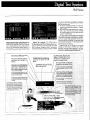
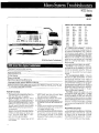
The 91 00 Serles can detect and i s )late faulty
components on all types of rnfcro socessor-
1.
-
~ g
ever before at the design stage, c ~ r i preduction, and in the teld.
And, you can automate your trovb eshoot~ng
procedureswith minimal programmil g; the tester's built-in Guided Fauft :solatior decision
tree does most ot the work.
.
woo*
.
[
-Emulative-Board-Testiwfar the Kernel
At the heart of Fluke's approach s a techniaue known as emulative board ter !ina - so
- c ~ ~ e d - b e c a ~ s a ~ i t ~ n ~ o utatf2nloj-the
~ves~em
board's nnicroprocessor.This lechnrc ue 1s preferred by board manufacturers the kuorldover
Emulative b a r d Test: Test micropraeessor-based
digrtal circuitry from the
for finding faults in kernel crrcuitry, be zause il is
-the only technique that tests a boar1 from the
micraorocessor outward
"~nsideouL" Consequently. it lets 4 IU lo-%
more faults, more quickly, than i ny ofher
Automated Functibnal (GO/MQGO) Tests and Guided Fault !sofalion (GFfj Test
approach.
Integrated program deveyopment environment
Micropr%easor intehea pods. T emurate
the Soard's microprocessor, you self :t the miAutomatic functlcnal tests of pP kernel
croprocessor interface pod that corre ;ponds to
Automatic generation of G f l dedsion tree
themi~ropro~essor
OF the board, Pod: areavaifable for over 50 microprocessor chi^ s, ~ncludSupport for over 50 rnieroprocessors
ing the new 80286. All exlsllng Fluke I iicroprD110 module and singie point probe to "closethe 1oap" in measurement or stimulus
cessor interface pods can be used wrlh Ihe
9100 Ser~es.
- The 8 0 2 8 W w ' - w i t k t k 9 W D A , 9 + ~ - 5 A m a
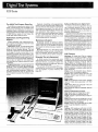
The 9100 Series is the newest member of ed tests, developed on the 9100R. to Ihe factory frame allows a s~ngleInstruction b eakpoint
lloor or servlce center. A n easy lo use interlace and prevrdes8 K-bytes of overlay RAI 1. includFluke's family of digital testers and troubleshooters. It is designed tor tast. cost-effective allows any operator to quickly test and troubleingtha advanced podfeatures\see pa le 27 4
aulamation of your test and troubleshooting shoot. Guided Faull lsolat~on(GFI) programs pod information).
Isolate
faults
lo~he~odeJevel,so
b
~
t
f
i
f
u
n
c
t
i
o
n
~
procedures~io~rnicroprocessor~based-digital-Total
control dlht bus,ln add~tion-tcccntainal testing and trouSlesflootfng can truly be aucrrcu ~tboards.
ing its own microprocessor, each pc d has its
Included In the 91 00 Series am two testers: tomated. The 9100A and 9105A cornb~neto
own RAM, ROM, and I/O, making it a :omplete
the QIOOA Digital Test System,which can be offer unmatched power, flexibilfty, and econokernel,The pod replacesthe board's r ~icmprbused both lor developing test software and as a my to factory board test and service center cessor, allowing the pod to control a bus-rere
pal
r.
stand-alone test station, ar.d the 9105A Digital
lated devices on the board. Pfugging 1 I the pod
Both feslers interface wrfh the unlt under lest also causes the clock c~rcuitof the bo: rd under
Test Stat~on,an execute-only tester that can be
(UUq through the foilow~nghardware compo- test lo be channeled to the pod's n ictopraused to execute programs developed om the
nents:
9100A.
cessor, SO that tests can be performet wilC the
A microprocessoc interface pod: the pod board running at itsnormal speed. A I UN UUT
Tho 91OOA ofiers fast and easy development
emulates
the
microprocessor
actrons
on
the
03funclionaltest and lroubleshootingprograms
function allows you to execute progra ns resldUUT.
wh~chslay ahead ol the increasing complexity
ingin the UUT's rnemory.Thisallaws~lrecution
A s~ngle-pointprobe to measure UUT reof digital boards. Test program design is highly
ol in~tializalion
programs and diagnost~c$.speedsponses at any node within or beyond the
automsled. gu~ding
the test or servlce engir ear
ing trou breshooting.
microprocessor kernel: the probe can also
through the development process. Combined
Automatic bus-iinamonitaring. Bus- ne manprovide stimulus at any node.
n~th
new state-ot-the-art test hardware, comiloringtakes place automatically w h e ~the pod
I
I
O
modules
whichallowtesting
of
upto
160
plete digital board test and repair ao~ulionscan
accesses the unit under lest. This mear slhat no
nodes simultaneously.
be crealed in record t~me.
prob~ng1s necessary to find bus faul s. It also
The9105ADigitatTeslSlationturnsa powermeans thai the pod can detect dynamic faultsful lesl solut~oninto an economical one. A t very
low cost. the 9105Adel1verspowerlul automat-
-
-
*
9101 Series
I
thosethatcome and godepending oniheactivity being performed - a s well as static faults.
Built-in BUS, RAM, and ROM tests. Using the
pods, you can quickly execute the9100 Series'
built-in BUS, RAM,and ROM test routines. Because these circuits operate the same way on
ail microprocessor-based boards, you can run
these tests as soon as you plug in the pod,
without writing any code at all. At the concfusion of each test, the system reports its findlngs
to the operator via specific fault messages.
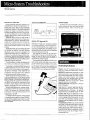
Functional Testing Beyond the Kernel
All of the devices interfacing with the UUT
may be used to stirnufate circuitry beyond the
microorocessor kernel.Typically the majority of
stimulus will b e generated from the microprocessor socket via the interface pod.
Sincethe pod can emulate any activity which
the microprocessor on the UUT can perform,
functional testing may be performed in the following steps. Partition the UUT into functional
areas, excite or stimulate a functional paltition
COMPLETE DIGITAL FAULT COVERAGE
from the pod, the single point probe 01 the I 1 0
Module, measure the outpi!t response from the
functional part~tionand compare the response
to the expected response from a known good
UUT.
110 modules for rapid fault isolation. One of
the innovations offered with the 9100 Series is
:he new type of circuit interface device for
lode-oriented troubleshooting: the I/Omodule.
This module, which lets you test all pins on a
chip at once, provides a qurck means of detectng and isolating fauits for signals up to 10 MHz.
It works with both synchronous and asynchro~ o u circuitry,
s
on cr off tha bus. And, because
you can Lse u p to four I / O modules at a time,
yo^ can testas many as 160pinssirnultaneously.
Modules may be clipped directly over the
chip via a DIP clip, available in configurations
,angins from 14 to 4 0 pins. Or you can use tho
9100Series 20-line flying lead module to deveiop your own custom connec:ions, connecting
the testerto the board edge, a bed-of-nails fixture, or a customized test fixture.
I
The 1 / 0 module lets you use a v ~rietyof test
techniques. You can use it to drive 3 node high
or low or to stimulate it with a st ing of data
patterns. It can also gather a wil e range of
response data, i n c h i n g taking a n ~de'ssignatu:e, sensing its logic level, and me 3suring activity on a node through frequeilc{ measuren l ~ n t sor event counting. Built-in clock connectors let you synchronize the n- 3dule to an
external clock when troubleshoot i g asynchronous circuitry.
TPe measurement may consist o signatures
gathered concurrently at several 7odes or it
may be the circuit resporise meas red by the
pod. Functional testing may be aL tomated by
fixturing the nodes critical forfuncti rnal testjng.
1/0Modules areactaptable, interfac ng with test
f~xturesfor functionat testing.
The 9100 Series testers provid ? flexibili!~,
several ways and alternatives toexe cise circuitry on the UUT to peif3rm reliabll functjonal
tests with a high degree of fault cc ierage and
confidence.
9100Series
Node-oriented Troubleshooting
If any of the built-in tests or functional tests
indicate that faults exist, y w r next step is to
perform node-oriented troubleshooi~ngto isolate the fault to a particular component. One of
the test techniques used in this process is signature analysis, in which the electrical "signature" of a node on the unit under test is
compared with that of the same node on a
known-good board. Other response factors
may also be compared, including logic levels,
event count, and frequencies.
Single-point probe for high-frequency signals. You can use the single-point probe instezd of the I/O mod2le for higher-frequency
s~gnals,up to 40 MHz. You can also use it tor
parts of the board that cannor be accessed with
an I/Omodule. Likethe 110 module, thesinglepoint probe can be used to drive a node high or
low. to stimulate a node, and to gather various
types of response data. it can take signatures,
sense logic levels, and count events or frequenc!es. An external clock module provides
leads for testing asynchronous circuitry.
Get as much - or as little
automation as you want.
-
With the 9100 Series, you choose the degree
of auiomation you want: Immediate Mode. for
manual operation; Guided Fault Isolation, for
automation of the troubleshooting process, or
Unguided Fault Isolation, for semi-automated
troubleshooting. If you do decide to automate,
you'll find that many of the 9100 Series'special
features -including the programming workstation, high-level programming language, and
built-in Guided Fault lsolation decision tree make the process easier and faster than you
ever thought possible.
Manual operation lets you start
testing
- immediately.
Immediate Mode lets you begin using your
91 00 Seriestester theiirstday you get it, without
having to write any program code at ail. With the
pod connected, you can compiete the built-tn
kernel tests. Then you can go on troubleshootinq, using your knowledqe of the cnit under lest
t ~ - ~ u ~ d e - The
~ o umalncarne
.
keypad ~ncludes
both hexadecimal and alphanumeric keys, so
you can manually enter whatever data IS needed
To troubleshoot in Immediate Mode. select
the first node you wish to test and attach the
selected interface device (l/O module or probe).
Then synchronize the interface device to the
appropriate bus cycle. Next, key in the stimulus
data and measure the response. Tqe 1/0 Module and Probe measurement resulls are shown
on the mainframe's three-line display. In the
case of the single-point probe, color annunciators on the probe itself indicate logic levels:
high, low or tri-state.
After completing the testing of the first node,
you select another node and repeat the process. When you locate the circuit at which the
input data is good butthe outputdata is bad, you
have successfully isolated the fault.
Obviously, to be able to work effectively in
lmmediate Mode, you need a high degree of
familiarity with the board under test - both to
determ~nethe best probing sequence and to
recognize whetherthe response is good or bad.
Automatic operation guides the
operator from start to finish.
The 9100 Series' Guided Fault lsolation capability allows automation of the troubleshooting
process. In this mode, the operator enters no
data and makes no dec~sions.All necessary
data - stinulus routines, reference lists, parts
lists, known-good responses, and interconnectivity information - are contained in the program. The system tells the operator whatto do a1
each step of the process and interprets all response data.
Once a Guided Faul?lsolation program has
been wrrtten, the only action required to initiate
it, is to tell ihe system which nodes aresuspected of being faulty, so it will know where to start
the node-oriented troubleshooting. This information can either be entered by the operator or
passed to the GFI program from a prior functional test.
At each step of the process, the system tells
the operator which node to probe, using a graphicdisplay to assist in locating the pin in question. As soon as the operator indicates that the
interface device isattached, the system runsthe
appropriate stimulus program, reads the response, and compares it with the known-good
response for that node. If the response is good,
the system directs the operator to the next suspect node. If it is bad, the system uses its built-in
back-tracing algorithm, togelher with the reference data in its files, to locate the chip driving
the input to the bad node. This process continues until the system has traced the fault back
to its source.
A key advantage of the system's Guided Fault
Isolation capability is that all operators can benefit from the knowledge of your most experienced test engineers. Once yourtest engineers
write the Guided Fault lsolation procedures,
lower-level operators can execute them, saving
you considerable labor costs.
Semi-automatic operation lets y IU choose
the troubleshooting sequence. For, ern!-automatic troubleshooting, you can us1 the 9100
Series to perform Unquided Fault Iso ation. This
Fauit Isolation, lxcept that
mode is like G ~ i d e d
the operator decides which node to probe,
However, much of the m a n ~ a ac!
l vity is removed from the process, so you c: n troubleshoot more rapidly.
Once a node is selected, the appr )priate stimulus routine is executed and the re ;ults of the
stimulus are displayed. In this way, tt e operator
guides the lauit tracing procedure.
For experienced troubleshooters vho prefer
to follow their instincts rather th; n moving
throuyh a set troubleshooting seqi ence, Unguided Fault lsolation is the best tec mique.
The 9100A Programming Envitonment
(With Option -004)
From its built-in back-tracing algc -ithm to its
easy-to-use programming language, the 9100
Series lets you develop fully automat sdtestand
troubleshooting routines in a matter of days or
weeks, as opposed to the months c : aevelopment time required by many others1 stems.
Built-in GFI decision tree. The 91 KIA's specially designed back-tracing algorit i m makes
all the decisions about the troublesk ~ o t i n gsequence, allowing the programmer t~ enter the
necessary information in simple dati -base format. Information is stored in five kin( s of files:
0 Stimulus programs Lo test each lode. The
programs are designed to reveal ; II possible
faults that could cause a particu 3r node to
fail. They don't need to be elabora e, however; in many cases, a series of reac 5 or writes
at the appropriate address is sufl cient.
Known-good responses to con pare with
UUT responses. After developing a stimulus
prograrr for a node, the Drogra nmer can
use it on a known-good board to jetermine
what a good response looks like For each
node, the programmer can seiet i the most
appropriate type of response: sigr stvre, logic level, frequency, or event coun . An interactiveprogramprovidesguidance~I dsueloPing these files
A reference list relating the devit e number
to the type of device. This is a sin ple matier
of linking each device reference I umber On
the UUTto the typeof device usec (e.g., U2 '
2114), so the system will know wt ich partto
look ~p in the parts library.
e A parts library that explains the re lationship
of input pins to output pins. GFI ,equires a
par!s iibrary with a description oi each pad
on the UUT. A part description sl ecifies all
input pins which are related to e, ch output
pin. A fibrary of the most comml n parts 1s
provided with the 9100 program ning SOAware A field-oriented editor allc ws you to
add custom partsorother parts nt t included
in the standard iibrary,
/
9100 Series
-
Inferconneetivity data, Indicatingwhich devices and pins make up each node. The
back-tracing algorithm uses this information to isolate the fault to a single cornponent If this inforrna!ion already exists in a
CADlCAE file, you may be able to download
it directly, saving data-entry time.
Special test tanguage. The 9100A uses a
programminp language designed specificafly
for developing test and troub!eshooting routines. Its command list incorporates all of the
9700 functions, program control constructs,
and allowed variables, making it a well-rounded
language tor writing test programs.
Numerous features are desianec into the
program to make tne programmer's j )b easier.
Key among these are:
Provision for delault entries on n ost commands, simplitying the process o creating
test routines.
Built-in fault handlers that you car incorporate in your routires. (You can a!! 2 Choose
to override these built-ir fault han jkrs with
custom-created ones).
You can write functional tests inct rporating
the microprocessor interface gad, I/[ module,
and probe. A debugger is prov~dedw th breakpoint and single step capabitlnes to help you
quic~ly
locate any problems.You can also wr~te
administrative programs-for examp e, to track
board failures and the associated fa ~ l t ycomPOnene for future analysis
Programming for the 9100A is Ierformed
through an 80-cotmn, 24-line CI T and a
standard computer-style keyboard. The keyboard also includes nine soft keys wi h built-in
functions to speed program develop1lent
I
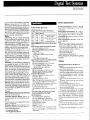
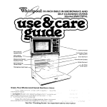
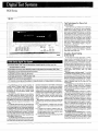
powerful Motomla 68000 mrempmcassor
!at ~ ~ C U I I KI
M aTl tests.
at&
useid forput!nnsof tna board thatcannot
be accessed wltn the li0 mOEue
l . A clock
~ o l u l e(nod shown) pawides connectlcns
.
~ w oA S - ~ 2 %send
pwts a l ~ wdata
transfer to and Imm the tester. One IS
.-
.
,
.
nn 11omodu1a
lea voutcsiudtp4 Ip/nsat
:
.
.
.
. . .-
2
9100 Series
The 9 i 0 5 A Test Program Execution
The 9105A is an execute only verslon oi the
9100A. It performs the same irnmedrats mode
operations as the 91006 and it will execute all
programs wr~ttenon the 9lOOA but you can not
write programs with the9105A. it has 7.5 Mbyte
a l RAM memory space and two f l o ~ p yd~sk
drives rather than a hard disk drive.
Applications and Programming
Contract consulting and programming*
Fluke's contract consulting and programming
services ofler still o t h e r o ~ t l for
~ napplicalions
~
and programming support. You can contract
with us 'for consulting help as you work on your
o w n applications and programs, or you can
Pave us simply develop programmed routines
lor you, custorn17ingthem to your parlicular
products and procedures. Contact your local
Fluke representative for availabll~ty.
Maintenance Supporl.
Fluke's apptication and programming supporl programs are designed to meet the needs
of a wide variety of users.
Applications course. The 9100 Series offers
you a choice of Zest techniques as well as a
variety of, circuit-interlace devices. The best
choice for a particular situat~ondeperds both
on the type of circu~tryinvolved and on your
objective (lunclional lest, fault isolatfon, elc)
Fluke's applications course shows you how Eo
apply the 9100 Serles to a wlde range of circuits
commonlyfound In microprocessor-based systems, so you can select :he most appropriate
test technique and inte7lace device lor each
appl~cation
Programmingcourse. 'ProgcammlngThe 9100
Series is easy, but you may strll benef~tfrom
guioance In how to QeVeiOp effecrive Guided
Faull lsolat~anroutines for drfferenllypes of lest
and troubleshooting procedures. Fluke's programming course wrll help you gel l h e most
Irom the system's Guided Fault lsofat~on
capabilities.
Worldwide network at technical centers.
Fluke's worldwide network of technics! centefs
makes rt easy for you to maintain and service
your system, no matter where your operation IS
?oca!ed.
Standard Warranly. Your 9100 Series tester
comes with a 90-day warranty, including b o h
time and materials. Warranly service is avaifab!e at any Fluke lechnrcal cenler, worldwide.
Extended Warranty Agreement
All 9100A product line components come
with a 90 day warranty. A one year, renewable.
Extended Warranty. covering all repairs wilh
performance testing. lncludlng parts. labor and
return surface ire~ghtcosts.
This warranty will be discounted 15% i f putchased with the instrument or 7% rf purchased
prlor lo expiration al producl warranty. See
page 453.
,"
Sotfwara Mainlenance Agreenent
A software maintenance agreeme1 t is a one
year renewable agreement that prr vides for
product upgrades during Ihe Cover. d period.
Sofrware upgrades include zny har Iware required for implementaiion.
Upgrades will include product impr Jverncnts
which increase ihe tunctionafity of tb E product
software and increase thethroughpu of test~ng
and !roubfeshooting. upgrades im wave the
operation ol the operator con!rol, pro Irammmg
sta!ion editor, programming language and hrctlons, Gu~dedFault Isolation progran mlng and
thel~0dev1cessuchasthedisltsandzommunicatfon ports. Some upgrades ~rnproe the operation ol existing capab~l~ties
and ;ome upgrades add new cspabilltres. Future -najor enhancements will be sold separately.
9100 Features
Mainframe: 20 Mbyte Hard Disk fo: program
development and storage (91001). Single
(9100A) or Dual (4105A) 3.5 inch n 40K- byte
formatled MicroFloppy Drivesfor soft) rare loading, storage and copying. 16 bit p1 with 2.0
Mbytes (9100A) Or 1.5 Mbytes (91051) of Internal R A M lor program and data storas 2. Plug-in
slots lor 1 pod s r d 4 Parallel 1/0 Mod ~ l e sDual
.
RS-232 interlaces, one system refere ,cod. one
earth rebrenced.
Display: 3 line. 4 2 characters vacuur 1 fluorescent dul matrlx with graph~cscapabi ty.
Keypad: User keyboard allows acc ?ss to all
funct~ons.Seldav used functions i re called
wi:h son kevs.
hislory using external clock.qvalified with ~ ! a r i
stop, and enable; Clocked 3-state I l g ~ clave'
hislory using microprocessar pod s! nc clock:
9100 Series
~~ynchronous
3-state level history in all modes;
selectable thresholds for TTL. CMOS, and
RS-232levels; Three logic level Indicaiors on
!hehandheld probe body, Probe output drive for
h gh, low or toggle synchron~zedto pod sync,
ex!erralclock or free run; Probe response button to signal the ma~nframeto gather response
data; Common lead fused for both the probe
clock module to provide ground fault proigtlon, w ~ t hblown fuse indrcation.
SottWafe
programming: The user creates and debugs
test or troubleshooting procedures with the
programmer's station option. This gives the
user full access to a screen oriented editor and
integrated procedure debugger. Test proced~resgenerated on the 9100A can be transported and executed or, other 9100A19105A
systems vta the 3.5 Inch micro-lfoppy media.
Language: The test language, called T L / l , is
used by a test engineerto specify automatictest
ard troubleshooting procedures. T L l l is an
eas~lyread high level language designed for
complete control of the functional test and GFI
test env~ronmentThe language includes the
9010A language testing concepts. Enhancements are wevided in the area of hult handling.
UUT initialization and intedace to GFI ~ r o cedures.
~ditt~ebu~:krocedu
editing
r e and debugging
are integrated to present a unified means 01
testing and modifying procedures. The editor Is
screen oriented, and always provides the user
with a current picture of the procedure being
edited. The debugger provides many features
such as break-polnt, tracing and accessto variables by name.
Gulded ProbelCllp TroubEeshooting: A menudriven software package makes it easy lor a
technician to specify node list information and
accumulate signatures from a good UUT. Ouring troubleshooting, this information is used to
~ u i d the
e operator.The operator i s told where tO
place the probe orlC clip totrackdown the fault.
Executing: The procedure execution environmer.t on the 9100A and the 9105A are identical.
Procedures generated on the 9700A will aiso
run on the 9105A. Procedures are transoorted
from the 9100A to the 9105A on a 3.5 inch nicro-floppy disk.
Manuals
Getting Started: A description of the parts of the
010 0 ~ ! 9 1 0 5 ~what
,
they do, how to connect
them, and how to power up.
Automated Operalions Manual: How to run
Fre-programmed test or troubleshooting procedures.
Technical User's Manuak How to run built-in
tests and manual or pre-programmed iroubleshooting procedures.
Applications Manual: How to write test or troubleshooting programs using the 91OOA's TLIf
Drogramrning language.
T L l l Reference Manual
Programmers Manual
Pod Supplemental Manual
--
--
General Specifications
9100A/9105A Electrical
Specifications
Single Point Probe Input ~hresholds
GUARANTEED ElGH
-2.BV
low or invalid
Input Impedance: 70 kfl shunted by less than
33 pF
Dala Timing for Synchronous Measurements
Maximum Frequency: 40 MHz
Minimum Pulse Width (H or L): 12.5 nsec
Minimum Pulse Width (tri-state): 20 nsec
Setup Times
Data to Clk: 5 nsec
Start. Stop or Enable to Clk: 10 nsec
Hold Time
Clk to Enable: 10 nsec
Cl k to Start or Stop: 0 nsec
Data Timing tor Asynchronous Measurements
Maximun: Frequency: 40 td Hz
Minimum Pulse Width (H or L): 12.5 nsec
Minimum Pulse Width Invalid {X)
TTL or CMOS: 100 nsec A20 nsec
RS-232: 2000 nsec *4C0 nsec
Transltlon Counting
Maximum Frequency: 40 MHz minimum
Maximum Count: 16777215 +overflow
Maximum Stop Count 65535 clocks
Frequency Measurement
.Maximum Frequency: 40 MHz minimum
Resolution: 20 Hz
Accuracy: f250 ppm f20 Hz
Output Pulser
High: >3.5V @ 200 mA lor less than lops; @
1% duty cycle >4.5 @ 5 mA continuously
Low: <.8V@200 mAforless thar: ?OPE.;@ 3 %
duty cycle <4V @ 5 mA continuously
Clock Module Specifications
Inpu! Threshold: 1.6V k0.2V
Input Impeoance:50K shunted by less than 10
PF
Clock, Start, Stop, and Enable Input Speed
Maximum Repetition Rate: 40 MHz
Minimum Pu!se Width: 12.5 nsec
RS-232 Interfaces
One isolated (system referenced)
One non-isolated (earth referenced)
Baud Rates: 110, 134, 300, 600, 1200. 1800,
2400.4800,9600.?9200
Parily: Odd, even or none
Daia Bi!s: 5. 6. 7, or 8
p o p aits: I. 1.5.2
XONIXOFF (Ctrl-SICtrl-Q):DisaSlelenable
Clear to Send: Disabfeleclable
New Line: Carriage Retutn/Line Feed or Carriage Return
Operating Temperalure: 5OC to 27'( 95% RH
maximum (non-condensing);27'C to 10°C; RH
decreasing linearly from 95% to 5 1% (noncondensing)
StoragelShipping Temperature: -20'1 :to 60°C;
846 to 80% RH, non-condensing; mit ro-floppy
nscia lkinited to 5°C to 60°C. 8 to 80°h /0H
non-condensing
Line Voltage: 90 to 132Vac 47!o 440 3z; 180 I0
26SV ac 47 to 63 Hz
Power Consumplion: Mainframe, I! OW rnax;
monitor, 50W rnax
Slze:
Mainframe: td.0cm H x 34.3cm W x 50.8 cm D
(5.5 in x 13.5 in x 20.0 in) Monitor: 30 53 cm H x
33.53 cm W x 33.00 crn 0 (72.02in : 13.2 in x
13in)ASCll KeySoard:5.02cm H x 2 .15cm W
x 47.2 cm D (2.0 in x 8.33 in x 18.51 in)
Weight:
Mainframe 8.26 kg (18.2 Ib)
Monitor 8.44 kg (18.6 Ib)
ASCII Keyboard 1.59 kg (3.5 Ib)
Safely: Designed to meet the follow ng safety
s:andards: ANSIIUL 478, IEC 348. IE X35. and
CSA 5568
Options
9100A-003 Parallel I / O Mod!~ l e
Features:
CRC signatures with Start Stop. En: bleclocked :o pod or external clock.
CRC signatureswith stopderived f .om a programmable number of clock pulses. .Rer Start.
Enable can be derived from the ext ?ma1enable line, or from Pod Sylc, orcar) be f rrced true.
.Programmable slopes on clock, tart, stop,
and enable.
CRC signatures can be taken do .ing Ovecdrive.
Transition counter gated by e x t ~n a l Start,
Stop, and Enable.
Frequency measurements to 10 M i z .
Clocked level history using exte~nal clock;
qualilted with S:art, Stop, and Enablt .
Asynchtonous level history.
Drive of any arbitrary pattern of 0.1, or 3-state.
comparison of any arbitrary 40 )it pattern
wi:h a programmable 40 bit pattern o- Osard 1 s.
True comparison available as a fi ult within
T t / l programs or as a message dul ng irnmediate mcde operation. The hardw Ire signal
(OCE), is also availableon theoutsidc of the I I O
module.
Logic thresholdsswitchable betwr en CVOS
and TTL.
F a m ~ l yof DIP and SMT logic clil modules
with response button to start respon ie gathering.
Common lead fuse protection, f )r ground
fau!t protection with blown fuse indir ation.
9100Series
-
Electrical Specitications
Data Output Specifications:
Current, time >lo mS:'200 mA
Current, <0ImS: c 2 A
Pattern Rate, 1 module driven: 35 kHz
Pattern Depth. (1 module driven during 10 rnS
high current pattern drive mode): 256patterns
Max current, per pin {driving high): 250 mA
Max current, per pin (driving low): 150 n A
Data Inputs: Input impedance: 50 k R min
Input Thresholds
h g h or invalid
GUARANTEED INVALID
tow or invalid
GliARANTEED LOW
0 6V
0.OV
0 OV
Clock, Start, Stop, and Enable Inpuls:
Thresholds: Logic low 0.8V max: Logic high
2.OV min
Input Current: 1 1 /JA
InputlOutput Overvoltage Protection: i 1 5 V f o r
one minute maximum, any pin, one at a time
Transition Counter
Max Frequency: 10 MHz minimum
Max Court (Transition Mode): 8388607 counts
{+overflow)
Freq Accuracy (Freq Mode):k 2 5 0 p p m +2 Hz
Stop Counter
Max Frequency: 10 MHz
Max Count: 65535 clocks
Clock:
Max Frequency: 10 MHz
Mi11Pulse Wtdth. 50 nsec
Timing for Synchronous Measuremenls
Max Frequency of Clock: 70 MHz
Data Setup Time: 30 nsec
Data Hold Time: 30 nsec
M i n ~ m u mPulse Width (Start/Stop/Enable/
Clock): 50 nsec
Start Edge Setup Time (before clock edge, for
clock edge to b e recognized): 0 nsec
Stop Edge Hold T ~ m e(aftec clock edge, for
clock edge to be recogni~ed):10 nsec
Enaole Setup Time (before clock edge, for
clock edge to be recognized): 0 nsec
Enaole Hold Time (after clock edge, for clock
edge to be recognized): 70 nsec
Data Timing for Asynchronous Measurements
Max Frequency: 10 MHz
M~nirnumPulse Width (high or low): 50 nsec
Min pulse width (tri-state): 150 nsec
Data Compare Equal (DCE); Min pulse w ~ d t hof
Data and Enable: 75 nsec
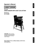
900C Series
Partial List of Processors Sul )ported
I
8;
h
rr i i
t
-
--
L
L
i
,r
i
1
It,,
O W
- U
U-U UyU
uu UL\.J
U U ULIU k"J
uu
bllJL;I
f
'
--
I
*
tad
9010A Micro-System Troubleshooters
P r e p r o g r a m m e d kernel test routines
Simple peripheral troubleshooting
Keyboard data entry
display
-32-digit
Power-~:, self-test
Keystroke programming 1901OA oniv)
- -
Language compiler optional (9095A and 9010A)
Communjcatrons
-- rnterface (RS-232G ISoptlanai for 9005A and 901OA, either RS-232
- or IEEE 488 i s standard for 9020A)
Special Functions
(a) Preprogrammed functorial :ests, offer structured testing and troubleshooiing ofthepp's
BUS, RAM, ROM and 110 Registers.
:b) TROUBLESHOOTING functions: simple
READ and WRITE commands allow you to
stimulate and observe responses from periphi?ral inrerphase adaptersiPIAs, CTCs,and
UARTs) and circuitry beyond tbe ,UP bus.
Several special functions are available
(RAMP. WALK) with preprogrammed stimuus sequences.
(cj Optional RS-232: easy downloading of programs a r d test results to storage mediums,
printeis and other testers at remote locations. O p t i o n a l IEEE-488 for c o m puter coctroller operation (9020).
Id) TAPE deck controls for storing and reading
programs and UUT memory maps on the
mini-cassette.
(e) LEARN function which is used on a "known
goad" system, finds and maps RAM. ROM
and read/writable I/O addresses.
(f) Hexadecimal entry of address descriptors.
(s) MODE corltrol of tests and programs.
(t-) TEST SEQUENCING and ARITHMETIC keys
for creating urlique user-generated test routiles.
(i) PROBE controls used for synchronizing the
troubleshooting probe to LIP cycles and to
drive nodes high and/or low.
0) Pod design provides for easy servicing. Extensiveinput protection prevents damage to
the pod f r o n comnlon acc dental abuses
such as pluggirg the pod into the socket
backwards. Plug is inserted int3 socket on
pod for self-test Pinscan he protected there
when not in use.
Z80A
Z808
28001
28002
28003
28004
1802
1804
1805
1806
6502
6800
68000
68010
6802
6802NS
6808
6809
6809E
8031
8032
8035
8039
8040
804'
804-A
8042
8044
8048
8049
8050
8051
8052
8080
82 14
87 11
87 l I A
8i i2
8 i 14
8 i 18
8 i 19
8 i 51
80858
9E 10
8085-2
8086
8088
8C 166
81 188
81 266
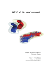
Thz9000 Series Micro-System Tro ibleshooters - 9005A. 901OA, and 9020A - Ire among
the most comprehensive troubles: ootlng instruments ever developed for Iocati. g faults on
mcropr~~cessor-based
systems. Th sy include
built-in preprogrammed test routine: for checking the entire microprocessor kernel bus, RAM,
ROM, and 110. Included is a trout eshooting
probe that you can use either to mc nitor logic
action on a r,ode-by-node basis ( r to inject
stimulus pulses.
The three trou~leshootersdiffer I rimarily in
their programming and system cap; bilit~es.
The 9010A IS a self-contained, p gramm mable model that lets you develop you own customized test programs. Using the ! OIOA, you
can perform specialzed guided fa^ 't-isolation
rout~neson any portion of a boa d's digital
circuitry.
The nonprogrammable 9005A ir sludes the
same built-in tests as the 9010A )ut cannot
generate new test routines. It can, hc wever, run
test sequences developed on the fOlOA and
downloaded from a minicassette tal e. With the
opt~onalRS-232C interface, you can ilso download test sequencesdirectly from thc 901 OAor a
host computer. Typically, you woc d develop
guided fault-isolation programs at E central location, using a 901C)A. and then r<n the programs at remote sites on 9005As.
The 9020A, designed for system; use, runs
test programs written and stored i 1 a system
controller or other computer. Yo1 can also
combine the 902014 with other test I istruments
totroubleshoot complex microproce isor-basea
products with s p ~ c i ameasurement
l
~ n control
d
problems. The9020A has no prograi i r i n g keys
or cassette taps capabil~ty,so test sequences
must b e executed through the RS-2 ,2C or IEEE
488 port.
Read t Write Emulation
The 9000Series Micro-System Trc ubieshooters eliminate tedius. manual probing echniques.
Instead, they take cor>trolof tne un . under test
by p i u g g n g into its rnicroproces ;or socket.
They then emulate the actions of t h microprocessor. both reading data from and vriting data
to the unit's RAM, ROM, and 110 ac dresses.
A
9000 Series
Built-in Tests
Flute has taken the lroubte oul of verilying
that the kernel -the hean of the microprocessor system - is operaling properly, by including built-in kernel tests in all the 9000 Series
Troubleshooters.Thesetesis, initialed by a single keylroke, check the electrtcal i~tegrityof
l h e microprocessorbus,:he readlwr~te
capability of the I/O registers. the data In ROM, and
RAM opera:ron. A f ~ l t hbuilt-in test provides
more extenswe R A M Csts when necessary,
checking for pattern-sensitwe fa~lures.
Thef~vetests, which cover mare than 50% of
the components on most boards, check for the
problems that are often the most difficultto identlfy and isolate - including failures thai lock up
the microprocessor bus. Even if the troubleshooters had no other capabil~lies,Ihe lime
saved by these built-in tests done would more
than justify their cost.
Of the five built-in tests, you should run the
buslest first, since it verlfies the integrity of the
microprocessor's basic communication network To test the remainder of the kernel, you
need to enter the location of RAM, ROM, and
IIO lorthe unit under te5i.soIhe troubleshoo?er
w ~ lknow
l
whataddressesto read lrom and wrl!e
to. You can enter this inlormalton manually
through the fron:-panel keyboard or download
~tfrom a rninicassetle
or, if yau have the
RS-232C interface, you can download it from a
host computer or system controller. If address
~nformationis no! readfly ava;labfe from the
unit's docurnentalion. there is a LEARN algorlthm to let you generate a memory map from
a known-good board. Once entered, memorymap informationcan be stored on a minicassette
for laler use (9055A1901 OA),
-
out uslng a logic analyzer or oscilloscope. Tesfs
~erformedinclude signature gathering. waveform capture,and event counting. For more information, seethe description of the bsynchronoue Signature Probe Opt~on.
Custom Test Programming an the
Fluke 90106
The 9010A lets you wri* your own cornprehens~vetest routines tailored lo the unique
character~sticsof the equipment you service.
These programs can inchde prompting messages to help guide your technrcians through
the test procedures. Once wraen, p u r test
programs can be stored on minicassettes for
later use - or for load~ngIn a 9005A.
You can generate your own test software in
two ways. Flrst, you can develop short pmgrams right on the 90lOA's keyb~ard,nn much
the same way as with a scient~ficcalculator.
Secord, for more extensive test routines, you
can use the 901DA's Language Compiler, developing programs off-line on a personal computer and thee downloading them to e~thera
9010A or 9005A. The Compiler runs on a
number of popular personal computers. lncluding the lBM@PC and Kay Pro II@as well as on
tae Fluke 1720A and 1722A Instrument Cont-ollers. For more ~nl~rrnatlon,
see the descnptfon el the Language Com3rler on page 163.
A Powerful 'besf System Using the
Fluke 9020A
The combination of a Fluke 9020A Microan IBM or IBMcompat~btepersonal computer and Fluke's
TeslWriterl' software (see page 164 for more
information) gives you a powerfu: system b r
performing large-scale gu~dedfault-isolation.
Beyond the Bus
In this system, the 9020A is used to stimulate
The9000 Series Tfoubleshoorersaren't limitand gather response lnfurmatlon Irom the unit
ed to find~ngkerne!-related problems: they can
under test; the personal computer acts as bolh
also isolate failures In synchronous clrcuilry
the system controller and the storage medium;
outside the bus. TheIroubkeshootinp probe that
and the TestWriier software rninlnrzesprogramcomes with the 9000 Serles will help you track
mer tlme through stmpliried dala-entry prosuch off-the-bus failures to their source.Th~s cedures.
probn is a powerful lau!l-finding tool, useful
This test configuration makes developingtest
bolh lor monitor~nglog~caction and for injectprograms so easy ttlat it opens the door to new
Lng stimulus pulses.
types of teslr - tests that previously would
In mon~toring,or response mode,the troublePave required too much programming llme to
shooting probe takes signatures, counts events,
'be cos!-effective. And it makes perlorming,the
and shows h~ghllowlogic states in each node
tests so sirnp!e that virtual!y any technician can
probed. In stimulus mode, ~tcan inject htgh or
immediately begin troubleshooting,without golow pulses to stimulate readouts,prlnt heads,
ing through the entenstve training required to
interfaces, or other devices. Drlven by a sync
use mcfe traditional test techniques.
oulse Imm the tnterface nod. the orobe can be
kynchronizadlo various micropro&asor events,
such as valld address or data periods on the
mlcroproeessor bus. You can also choose to
use it In 'wee run" mode, lnjealng 1 kHz pulses
at the conzacted nodes.
To further exlend thecapabilities of the troubleshooting probe, add the asynchronous signatureoption.Thisopt~onl&youlestasynchronaus circurts localed outsideihe microprocassot
bus structure (such as DMA controllers. video
controllers,and vtdeo-generationcircuits) with-
System Troubleshooler wlth
Oplirnns and Accessor!es
9000A-910 Utility Tape
The 90OOA-910 Utility Tape cor tains many
programs designed to enhar ce the. ~perattonof
Iha 9010A. These ~nclude:
Merge Tape - Lets you read SI lecific programs lrom a minicassettetape, rr numbering
them asdesired and mergirg thc n wilh programs already in the 9010A. Wlt. I this uf~lity,
you can combine programsfrom w o w more
tapes onto a s~ngletape.
Frequency Counter - Lets you u ;e the troubleshmting probe to measure he luencies of
up la 6 MHz.
Setup - Lets the SOIDA ope ator make
changes in the setup menu whilc the system
i s under program control.
Probe Pulse,
Lets the 901C 4 operator
change pulser status while tht system is
under program controi.
Regrster Additron and Subtractic i - Allows
forthe addrtlon or subtraction ol t ie co~lents
01 Iwo registers while the s y s t ~n is under
program control.
The VtlI:ty Tape comes witha map ~ aand
l one
minicassette that describes how to lse each of
these programs.
-
900C Series
9000A-006 Asynchronous Signature
Probe Option
The 9000A-006 Asynchronous Signature
Probeoptiongives you high-powered faultisolation capabilities for asynchronous circuits Iccated outside the microprocessor 3us structure.
With this option, you no longer need to augment
your 9000 Series Troubleshooter with a logic
analyzer.
By adding the Asynchronous S~gnatureProbe
to the 9090 Ser~es,you gain the ab~lilyto perform real-time measurement of such asynchronous circuits as:
DMA controllers
b Video controllers
m V~deo-generationcircuts
b Communication circu ts
r Perapheial controllers
The AsynchronousSignature Probe provides
three district troubleshooting ~ e a s u r e m e n t s -
9010A Language Compiler
If your test routines are short, you can develop them right at the keyboard of the 9010A. For
more extensive test rout,nes, you'll find ~teasie:
to work off-line on a p e r s o ~ acomputer.
l
using
the 9010A Language Compiler and downloading the results to the 9010A.
The Language Compiier lets you write exten- I
sive test and troubleshooting routines more
quickly and conveniently. The Compiler is available in several versions, offering compatibili:~
with the following computer systems:
r IBM" Personal Computer
Kay Pro'" II
0 Fluke 1720A and 1722A Instrument Controllers
Sophisticated development toolscome with the
Compiler to speed the program-development
process. Using these features, you can:
Share common test rout~nesamong multiple
programs through a Fiie inclusion features,
linking them together automatically at compile time.
1 Save time when entering code b y using keyword abbreviations, optional command keywords, and shorthand notations.
Assign symbolic names to your programs,
labels, and registers, making it easier to understand and remember the purpose o f the
ditferent program sections.
Document programs with comments imbedded within the program 'isting, making ;hem
easier to follow shou!d you later wish to revise them.
Signaturegathering, using thc c z l i c rcdundancy check technique.
Wavefornr capture, in which tk 2 probe-tip
data stream is sampled every ?O nanoseconds for a total of up to 32 data s ~ m p l e sThe
.
results of this sampling are boj 1 displayed
and stored.
Event count~ng,a powerful to )I for node
characterization. Using this feat re, you can
count events from the probe tlp either continuously or through a measurer ?nt window.
A 24 bit regis:er allows you to re[ ord over 16
miillon events.
The Asynchronous Signature Prt be consists
of a circuit board, installed in the 1000 Series
mainframe; aclock module, which 1 ~ c k up
s timing and control signals from the un t under test;
and a special set of operating prc grams contained on a min~cassettetape.
*
*
9000 Series
Test Station Configurarlon
Fluke's TestWriter software. combined with
the 9020A Micro-SystemTroubleshooter, an interface pod. and an IBM (or IBM-compatible)
personal cornpuler, makes it easy to develop
guided fault-isolation or automated diagnostic
qrograms for digital circuit testing. In this configuration,the personal cornpuler, communicaiinn w ~ t hthe 9020A-001 through its RS-232-C
interface. acts as both a system contro