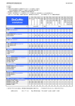
1
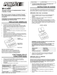
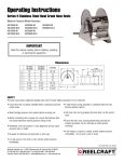
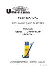
USER MANUAL
AUTOMATIC DUST VACUUMS
MODELS
UR500VAC
UR500VAC-E
UR500VAC-A
UR480VAC
UR480VAC-E
UR500VAC-J
UNI-RAM CORPORATION • ONTARIO • CANADA
Revised 2006-02
MANUAL - AUTOMATIC DUST VACS - UR480-UR500 SERIES
Revised 2006-03
CONTENTS
INTRODUCTION ................................................................................................................................... 3
CAUTIONS AND WARNINGS .............................................................................................................. 3
PREPARATION ..................................................................................................................................... 4
NOTES ON USE AND OPERATION ...................................................................................................... 4
ACCESS TO THE MOTOR COMPARTMENT ....................................................................................... 4
MAINTENANCE AND TROUBLESHOOTING ...................................................................................... 5
FEATURES AND SPECIFICATIONS ..................................................................................................... 5
REPLACEMENT PARTS ....................................................................................................................... 6
WARRANTY ............................................................................................................................................7
2
MANUAL - AUTOMATIC DUST VACS - UR480-UR500 SERIES
Revised 2006-03
INTRODUCTION
Uni-ram holds many patents on designs used in its innovative products. Every machine is rigorously
tested for compliance with stringent Quality Assurance standards. Follow the notes on preparation, use
and operation to operate this machine safely and effectively. Ensure that this manual is readily available
to the operator at all times. If you have any questions about the operation of this machine, contact:
North America:
Uni-ram Technical Service
1-800-417- 9133
Other Continents:
Contact Your Supplier
CAUTIONS AND WARNINGS
•
•
•
•
•
•
•
•
•
•
•
•
•
Wear safety glasses and follow all local safety regulations.
Do not use as a vacuum cleaner: use only with Pneunamtic Power Tools that have vacuum return
capability.
Do not leave the unit unattended when plugged in. Unplug from outlet when not in use and before
servicing.
To reduce the risk of electric shock, do not use outdoors or near water or wet surfaces.
Do not use with a damaged Power Cord or Plug. If the unit is not working as it should or if it has been
dropped, damaged, left outdoors or emersed into water, contact Uni-ram for service instructions.
Keep the Power Cord away from heat.
Keep all openings free of objects, dust, hair, lint etc to prevent reduction of the air flow.
Keep hair and clothing away from openings and moving parts.
Do not use without a filter.
Turn off the Power Switch before unplugging.
The electric models must be plugged into a properly installed, grounded outlet.
The filter is water resistant and washable in water. Do not use high pressure air or solvents to clean it.
Cleaning with a soft brush is recommended.
Do not operate the unit without a Vacuum Hose attached.
3
MANUAL - AUTOMATIC DUST VACS - UR480-UR500 SERIES
Revised 2006-03
PREPARATION
Note: Item numbers given below refer to the parts listing on page 6.
1.
2.
3.
4.
5
6.
7.
8.
9.
10.
11.
12.
13.
Check for transportation or handling damage.
Make sure all parts and accessories are included.
Release the two Rim Clamps on the unit and remove the Vacuum Head Assembly.
Make sure no packing material is left inside.
Check to make sure the Filter is seated firmly. If not, tighten the Round Cap Nut at the base of the
filter unit.
Remove the Vacuum Hose Assemblies from the bag (one for the UR480VAC and two for the
UR500VAC). The Air Hose (the smaller of the two) protrudes at both ends and is longer than the
Vacuum Hose.
Connect the Quick Coupler male end to the Air Inlets located on the Vacuum Head Assembly.
For easy tool changes, install a Female Quick Coupler (not supplied) to the 1/4” NPT connector provided at the other end of the Air Hose and a compatible Male Quick Coupler (not supplied) to the air
tool.
Lift the Vacuum Inlet covers and insert the Vacuum Hoses.
Connect the air supply to the Air Inlet Fitting (1/4” NPT female threads) located at the back of the Vacuum Head just above the Power Cord. The air pressure should be adjusted according to the pressure
requirements of the air tools. Do not exceed 150 PSI (10.3 kg/cm2). Some pressure drop is normal
due to the length of the hoses. Air pressure 20-30 PSI (1.5-2.0 kg/cm2) higher than what is specified for the air tool is recommended. To protect this unit and the air tools, an air line moisture
filter/lubricator and a pressure regulator are also recommended.
When the power supply is connected, the Pilot Lamp on the Vacuum Head will come on. Make sure
the correct voltage is being supplied.
Install a Dust Collector Bag inside the Main Body (bottom portion) by overlapping the top edge of
the Bag around the the top of the base container. Make sure that the Vacuum Balance Tube (square
tube) protrudes through a hole in the Bag (see the picture on Page 5).
Return the Vacuum Head to the unit and lock in position with the Rim Clamps.
NOTES ON USE AND OPERATION
1. The vacuum system is controlled by the on/off switch on the air tool. However, to clear the hose after
use, the vacuum will continue for a few seconds after the air tool is turned off.
2. The Vacuum Motor will momemtarily come on when the air tool is connected to the unit.
3. A Power Switch on the Vacuum Head Assembly overrides the on/off control by the air tool. This switch
should be turned off during regular usage.
4. The top of the Vacuum Head is designed to be used as a shelf to hold tools, sandpaper etc.
ACCESS TO THE MOTOR COMPARTMENT
Service work must be performed by a qualified service technician.
1. Remove Protector Molding from the top edge of the Vacuum Head Assembly and keep for reinstallation.
2. Remove the three mounting screws and lift off the Vacuum Head Cover.
3. Pull out the Separator.Plate (Item 2, Page 6) by the handle.
4. To re-install the Separator Plate, push it down until it sits firmly on top of the motor.
5. Re-install the Vacuum Head Cover and Protective Molding.
4
MANUAL - AUTOMATIC DUST VACS - UR480-UR500 SERIES
Revised 2006-03
MAINTENANCE AND TROUBLESHOOTING
1. The cartridge filter is water resistant and washable in water. Do not use high pressure air or solvents
to clean it. Cleaning with a soft brush is recommended.
2. After each use, knock the dust off the filter and after one hour of continuous use, lift out the Vacuum
Head and check for dust accumulation. Replace the Bag if necessary.
3. If there is a decrease in vacuum performance, check the filter and check the vacuum hoses for blockage.
FILTER PART NO.
27-175 STANDARD
27-177 HEPA
PLASTIC BAG (PART NO.50-970)
FEATURES AND SPECIFICATIONS
Uni-ram Automatic Dust Vacs are powerful turbine vacuuming systems that extract dust and debris at 100 CFM and greatly reduce sandpaper consumption.
• Portable; for use with air powered vacuum assist tools • Air flow: 100 CFM
• Automatic activation by air tool
• Air pressure: variable to 150 PSI
• Two stations/operators (UR500 series)
• Fume grade filter standard, HEPA available
MODEL
WORK STATIONS
POWER (V/W)
UR500VAC
UR480VAC
UR500VAC-E
UR480VAC-E
UR500VAC-J
UR500VAC-A
2
1
2
1
2
2
120/1350
120/1350
240/1350
240/1350
100/1350
NON-ELECTRIC
SEALED VACUUM
98.6” WATER
98.6” WATER
98.6” WATER
98.6” WATER
98.6” WATER
98.6” WATER
STANDARD HOSE
16 FT (4.88m)
16 FT (4.88m)
16 FT (4.88m)
16 FT (4.88m)
16 FT (4.88m)
16 FT (4.88m)
DUST COLLECTION
PLASTIC BAG
PLASTIC BAG
PLASTIC BAG
PLASTIC BAG
PLASTIC BAG
PLASTIC BAG
CARTRIDGE
CARTRIDGE
CARTRIDGE
CARTRIDGE
CARTRIDGE
CARTRIDGE
54/24
50/23
54/24
50/23
54/24
54/24
19X19X44”
19X19X44”
19X19X44”
19X19X44”
19X19X44”
19X19X44”
FILTRATION
SHIP WEIGHT
(LB/KG)
SHIP SIZE (WDH)
5
MANUAL - AUTOMATIC DUST VACS - UR480-UR500 SERIES
Revised 2006-03
REPLACEMENT PARTS
ITEM
PART NO.
DESCRIPTION
PART NO.
DESCRIPTION
1
27-141
Neon Lamp 100-120V
27-151
Power Cord Assembly 16’ CSA
1.1
27-142
Neon Lamp 220V
26-729
Static Prevention Wire
2
26-114
Separator Plate
26-100S
Vac Head Complete (Electric)
3
UFS25V-KIT
Flow Switch Assembly
26-100A
Vac Head Complete (Air Powerex)
3.1
22-200
Micro Switch Complete
27-129*
Motor Brush
4
27-102
Motor Holder Plate
5
KIT-26123*
Vac Motor Kit, 1350W, 120V
5.1
KIT-26127*
Vac Motor Kit, 1350W, 240V
5.2
KIT-26125*
Vac Motor Kit, 1350W, 100V
6
26-270
Vacuum Inlet Assembly, Left
6.1
27-103
Gasket Outlet Mount
7
27-218
Rim Clamp
8
27-175
Cartridge Filter, Large
8.1
27-177
HEPA Filter, Optional
9
27-381
Axle Shaft 1/2” x 18” ZP
10
11-161
Wheel, 6” Heavy Duty
11
27-384
Wheel Cap, 1/2” Axle
12
26-721
Hose Cuff 1.25”
13
26-718
Vacuum Hose, 1.25” ID, Short
14
QCM14MT
Quick Coupling, 1/4”, MPT
15
26-726
Hose Cuff Reducer, 1.5-1.0” OD
16
26-700
Hose Assembly, Complete, 16’
17
26-725
Hose Connector
18
10-168
Leg Support Ferrule
19
26-300-BK
Base Assembly
20
26-200S
Main Body Assy, S. Steel
21
PEC14
Seal Ring
22
26-260
Vacuum Inlet Assembly, Right
23
26-751
Air Hose, 3/8” ID
23.1
PET14X38
Hose 3/8” OD, Per Foot
24
26-111S
Vacuum Head S. Steel
25
NP-HAND572
Handle, Chrome Plated
26
QCF38HB
Quick Coupling, 3/8”, Female
26.1
QCM38HB
Quick Coupling, 3/8”, Male
27
27-131
Power Switch 120V
27.1
27-132
Power Switch 240V
27.2
27-133
On-Off Plate Power Switch
28
26-109
Moulding, Vacuum Head
29
26-101
Vacuum Head Cover
27-217-CP
Tubular Handle Chrome Plated
ITEM
* For units purchased before 2005-12, call before ordering
6
MANUAL - AUTOMATIC DUST VACS - UR480-UR500 SERIES
Revised 2006-03
Full Product Warranty
These Uni-ram products have been engineered and manufactured to high performance
standards. Each unit has been subjected to detailed factory testing before shipment.
This product comes with a one-year full warranty from the date of purchase. Uni-ram
Corporation reserves the right to repair or replace the unit, free of charge, to the original
purchaser if a part is found to be defective in material or workmanship as determined
by factory service personnel. The items listed below under “Conditions of Warranty” as
consumables are not covered.
Uni-ram reserves the right to direct the customer to ship the unit collect to the Uni-ram
factory or to an approved Service Center for repair using the Uni-ram Return Goods
Procedure or to repair the unit on-site. To prevent damage in transport, the purchaser
must ship the unit in the original packaging or use alternate adequate packaging. All
units must be shipped clean and free of solvent.
Conditions of Warranty:
As Uni-ram Corporation has no control over the working conditions or circumstances
under which the purchaser stores, handles or uses the product, Uni-ram makes no warranty or claim, either expressed or implied with respect to this product’s fitness for any
purpose or the result to be obtained from its use. This condition applies to the sale of all
products and no representative or distributor of Uni-ram Corporation has the authority to
waive or change these conditions.
This warranty applies only to the original purchaser and does not apply if the unit has
been misused, overloaded, neglected, altered or used for any purpose other than those
specified in the operating and installation instructions. Deterioration due to normal wear
is not covered by this warranty. Damage due to accident, transportation, fire, floods or
acts of God is also not covered. Units whose serial numbers have been altered or removed are not covered. Unauthorized attempts at self-repair or alterations by the owner
also invalidate this warranty. Interior or exterior finishes are not covered by this warranty.
Consumable Items are not covered by this warranty.
This warranty replaces all other warranties expressed or implied by statute or otherwise.
To make a claim, call Uni-ram Service at 1-800-417-9133 and quote the serial number
of the unit.
7