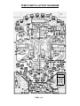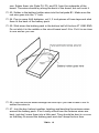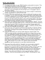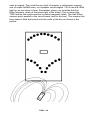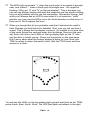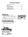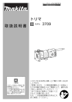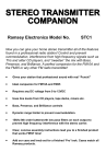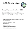
1
Tri-Field Meter Ramsey Electronics Model No. TFM3 Do a sensor sweep and learn all about electronic sensors. “See” the RF, Electric, and Magnetic fields around you in your home or office! A great teaching tool for kids of all ages; show them the invisible fields all around them. • Detect Rf from your radio transmitter, computer monitor, or cell phone. • Pick up the field from magnets around your house, even the earth! • “See” the charge on a staticky hairbrush or comb. • Learn how to use electronic parts as sensors. • Runs on 4 AAA batteries. • Small, handy size for portability. • Cool LED displays. TFM3 • 1 PARTIAL LIST OF AVAILABLE KITS: RAMSEY TRANSMITTER KITS • FM10A, FM25B FM Stereo Transmitters • AM1, AM25 Transmitter RAMSEY RECEIVER KITS • FR1 FM Broadcast Receiver • AR1 Aircraft Band Receiver • SR2 Shortwave Receiver • AA7 Active Antenna • SC1 Shortwave Converter RAMSEY HOBBY KITS • SG7 Personal Speed Radar • SS70A Speech Scrambler/Descrambler • TT1 Telephone Recorder • SP1 Speakerphone • MD3 Microwave Motion Detector • PH14 Peak hold Meter • LC1 Inductance-Capacitance Meter RAMSEY AMATEUR RADIO KITS • HR Series HF All Mode Receivers • DDF1 Doppler Direction Finder • QRP Series HF CW Transmitters • CW7 CW Keyer • QRP Power Amplifiers RAMSEY MINI-KITS Many other kits are available for hobby, school, scouts and just plain FUN. New kits are always under development. Write or call for our free Ramsey catalog. TFM3 Tri-Field Meter Ramsey Electronics publication No. TFM3 Rev. 1.2 March 2003 COPYRIGHT 2003 by Ramsey Electronics, Inc. 590 Fishers Station Drive, Victor, New York 14564. All rights reserved. No portion of this publication may be copied or duplicated without the written permission of Ramsey Electronics, Inc. Printed in the United States of America. TFM3 • 2 Ramsey Publication No. TFM3 Manual Price Only $5.00 KIT ASSEMBLY AND INSTRUCTION MANUAL FOR Tri-Field Meter TABLE OF CONTENTS Introduction to the TFM3 ................................... 4 TFM3 Circuit Description .................................. 4 Parts List ........................................................... 6 “Learn-As-You-Build” Kit Assembly ................... 7 Assembly Steps ................................................. 9 Parts Layout Diagram ...................................... 10 Schematic Diagram.......................................... 11 Setup and Testing ........................................... 17 Troubleshooting Guide ..................................... 20 Ramsey Kit Warranty ....................................... 23 RAMSEY ELECTRONICS, INC. 590 Fishers Station Drive Victor, New York 14564 Phone (585) 924-4560 Fax (585) 924-4555 www.ramseykits.com TFM3 • 3 INTRODUCTION Ever watch sci-fi and wish you had a “scanner” of your own? Now you can with Ramsey’s own TFM3! With this kit you can do a walk around of your office or home and see all the wondrous RF, magnetic, and electric radiation that you didn’t even know was there. You’d be surprised at what you’ve got around that’s spilling out RF or a nice magnetic field. The TFM3 has a three position selector switch that lets you select which type of field you want to detect: either RF, magnetic, or electric. The TFM3’s display consists of two LED bargraphs, one at the top and one at the bottom. These indicate the relative strength of the field you are detecting. All in all, it’s a great way to learn about the use of electronic components as sensors and own a little piece of sci-fi at the same time. This is a two-sided circuit board, but don’t be alarmed, there aren’t that many components, and there is a nice symmetrical arrangement that will help you place them on the board. TFM3 CIRCUIT DESCRIPTION Before we begin dissecting the circuit, let’s have a look at the “big picture” and see what it is that we’re trying to accomplish. What we want is to be able to detect RF energy, electric fields and magnetic fields. This should then be displayed on the two LED bargraphs such that stronger fields light up more LEDs. In addition, the bottom bargraph indicates the polarity of electric and magnetic fields as well as relative magnitude. Take a look at the circuit board layout and schematic. There are three sensors. At the bottom left part of the board is the RF sensor. It is made up of diodes D1, D2, capacitors C2, C3, C5, and R27. When radio energy passes through the antenna wire to pad P4, it induces a tiny current in the wire that is rectified by the diodes and produces a dc voltage that appears at the noninverting input of op-amp LF347. This amplifies the voltage and passes it on to the LM3914 LED display driver that controls the top “low sensitivity” LED display. It is called low sensitivity because it does not display polarity and does not have a “zero” point like the bottom display does. The top display will indicate the relative intensity of the RF being detected. This means that a stronger RF signal will light up more LEDs from left to right than a weak signal. At the bottom center of the board is the electric field sensor. It is made up of JFETs Q1, Q2, and resistors R24, R25, R26, R28, and R29. JFETS make good electric field sensors because they require a very tiny current into their gate to make them turn on. This is similar to a MOSFET except that TFM3 • 4 MOSFETS require zero continuous dc current to turn them on. MOSFETS were not used because they can be destroyed by the high voltages present in a statically charged household object. JFETS are relatively immune to these problems. There are two JFETS that make up the static field sensor, Q1 is an N channel type and Q2 is a P channel type. The pair allow both positive and negative electric fields to be detected. When a positively charged object comes near the antenna wire soldered into P5, transistor Q1 will begin to turn on and transistor Q2 will begin to turn off. In this case Q1 acts as a pullup and the voltage at the point between Q1 and Q2 will start to rise. When a negatively charged object is brought near the antenna wire, Q2 begins to turn on and Q1 begins to turn off. Q2 now acts as a pulldown and the voltage at the point between Q1 and Q2 begins to drop. This voltage in either case is amplified by the LF347 and then fed to the LM3914 display driver as well as the 3 LM324s. The LM324s control the bottom “high sensitivity” display. At the bottom right of the circuit board is the magnetic field sensor. It is made up of H1, and H2. These are Hall-effect sensors. They have an output voltage that is dependant on the strength of the magnetic field penetrating them. They are also sensitive to the polarity of the magnetic field. There are 2 of them to double the dynamic range of the TFM3. This works by having the 2 sensors point in opposite directions. For example when the North Pole of a bar magnet points toward the top of the board, H2’s output voltage decreases while H1’s increases. This is twice as sensitive as just using one sensor. The voltages from H1 and H2 are fed to a difference amplifier U4:B. The output from this amplifier is fed to the LM324s and the LM3914 to drive the top and bottom LED displays. TFM3 • 5 TFM3 PARTS LIST Sort and “check off” the components in the boxes provided. We do our best to pack all our kits correctly but it is possible that a mistake has occurred and we missed a part. Please note that physical descriptions of parts are for those currently being shipped. Sometimes the parts in your kit may have a different appearance but still have the same values. RESISTORS 22 1K ohm resistor [brown-black-red] (R1,R2,R3,R4,R5,R6,R7,R8,R9, R10,R11,R15,R16,R17,R18,R21,R23,R26,R31,R33,R35,R36) 2 1M ohm resistor [brown-black-green] (R28,R29) 5 10K ohm resistor [brown-black-orange] (R12,R13,R14,R30,R37) 1 20K ohm resistor [red-black-orange] (R32) 4 100K ohm resistor [brown-black-yellow] (R19,R20,R24,R25) 1 330K ohm resistor [orange-orange-yellow] (R22) 1 4.3M ohm resistor [yellow-orange-green] (R27) 1 50K ohm potentiometer (R34) CAPACITORS 4 .1 uF ceramic disc capacitors [marked 104] (C1,C4,C5,C6) 1 .01 uF ceramic disc capacitor [marked 103] (C2,C3) SEMICONDUCTORS Note: Chips may have other numbers and letters on them; the important numbers are those listed in brackets. 3 1 1 1 1 2 2 12 10 LM324 quad operational amplifier [marked LM324N] (U1,U2,U3) LF347N [marked LF347N] (U4) LM3914 display driver [marked LM3914] (U6) J177 P channel FET [marked J177] (Q2) 2N5484 N channel FET [marked 2N5484] (Q1) A3516LUA linear Hall Effect sensors [marked 16L] (H1, H2) 1N270 germanium diode (D1, D2) Red LEDs (D3,D4,D5,D6,D7,D8,D9,D10,D11,D12,D13,D24) Green LEDs (D14,D15,D16,D17,D18,D19,D20,D21,D22,D23) MISCELLANEOUS 1 1 1 1 4AAA battery holder toggle switch (S1) slide switch (S2) 22AWG wire, 18” TFM3 • 6 RAMSEY Learn-As-You-Build KIT ASSEMBLY There are numerous solder connections on the TFM3 printed circuit board. Therefore, PLEASE take us seriously when we say that good soldering is essential to the proper operation of your transmitter! • • • • Use a 25-watt soldering pencil with a clean, sharp tip. Use only rosin-core solder intended for electronics use. Use bright lighting, a magnifying lamp or bench-style magnifier may be helpful. Do your work in stages, taking breaks to check your work. Carefully brush away wire cuttings so they don't lodge between solder connections. We have a two-fold "strategy" for the order of the following kit assembly steps. First, we install parts in physical relationship to each other, so there's minimal chance of inserting wires into wrong holes. Second, whenever possible, we install in an order that fits our "Learn-As-You Build" Kit building philosophy. This entails describing the circuit that you are building instead of just blindly installing components. We hope that this will not only make assembly of our kits easier, but help you to understand the circuit you’re constructing. For each part, our word "Install" always means these steps: 1. Pick the correct part value to start with. 2. Insert it into the correct PC board location. 3. Orient it correctly, follow the PC board drawing and the written directions for all parts - especially when there's a right way and a wrong way to solder it in. (Diode bands, electrolytic capacitor polarity, transistor shapes, dotted or notched ends of IC's, and so forth.) 4. Solder all connections unless directed otherwise. Use enough heat and solder flow for clean, shiny, completed connections. TFM3 • 7 DOUBLE SIDED COMPONENT SOLDERING INSTRUCTIONS: You’ll notice that the circuit boards contain plating on both sides of the board. You only need to put solder on one side, the back. Just take your time and be sure to apply enough heat to the connections. Don’t be too afraid of overheating a component, most are fairly hardy and a weak connection will prevent your kit from working properly. Now, let's get building! Since you may appreciate some “warm-up” soldering practice as well as a chance to put some “landmarks” on the PC board we’ll first install some “hardware” components. This will also help us to get acquainted with the updown, left-right orientation of the circuit board. TFM3 • 8 TFM3 TRANSMITTER PC BOARD ASSEMBLY STEPS 1. Let’s begin in the lower left hand corner of the circuit board when you hold it so that you can read the writing and install the power switch S1. It doesn’t matter which way it goes in. 2. Now we will install the components that make up the RF sensor. Install D1, germanium diode next to S1. Observe polarity. Be sure the black band lines up with the stripe on the circuit board outline. 3. Install C3, .01 uF capacitor [marked 103], to the lower right of S1. 4. Install C2, .01 uF capacitor [marked 103], to the upper right of S1. There are two more components in the RF sensor, but they are at the other end of the board, and we will solder them in later to avoid confusion. 5. Install D2, germanium diode. Watch polarity again. 6. Now we will solder in the components that make up the electric field sensor. Install R28 1M ohm resistor [brown-black-green], next to D2. 6. Install Q1, N channel JFET [marked 2N5484], next to R28. Be sure the flat side of the transistor lines up with the flat side of the drawing on the board. 7. Install R29, 1M ohm resistor [brown-black-green], under Q1. 8. Install R24, 100K ohm resistor [brown-black-yellow], under R29. 9. Install Q2, P channel JFET [marked J177], across from Q1, Be sure it goes in the right way. The flat side faces the opposite way from Q1. 10. Install R26, 1K ohm resistor [brown-black-red], above Q2. 11. Install R25, 100K ohm resistor [brown-black-yellow], under Q2. 12. Install R21, 1K ohm resistor [brown-black-red], to the upper right of Q2. You have now completed the electric field sensor section! We will now move on to the magnetic field sensor section at the lower right of the circuit board. 13. Install H2, Hall Effect sensor [marked 16L] next to R25. Make sure it goes in the right way. The smaller flat face points away from the bottom edge of the circuit board as shown on the circuit board drawing. 14. Install H1, Hall Effect sensor [marked 16L], right above H2. Watch the way it goes in. The smaller flat side points down this time. 15. Install R17, 1K ohm resistor [brown-black-red], right above H1. TFM3 • 9 TFM3 PARTS LAYOUT DIAGRAM TFM3 • 10 TFM3 • 11 16. You have now completed the magnetic field sensor section. Install R34, 50K ohm potentiometer. 17. Install U2, LM324 operational amplifier [marked LM324], near the middle of the board. Make sure it goes in the right way. The notch on the top of one end of the IC matches the notch on the circuit board drawing. This amplifier along with U1 and U3, controls the bottom “high sensitivity” LED display on the TFM3. 18. Install R6, 1K ohm resistor [brown-black-red], right under U2. 19. Install R8, 1K ohm resistor [brown-black-red], on the right side of U2. 20. Install R5, 1K ohm resistor [brown-black-red], on the left side of U2. 21. Install R7, 1K ohm resistor [brown-black-red], on the right side of U2. 22. Install R4, 1K ohm resistor [brown-black-red], on the left side of U2. Incidentally, all these 1K resistors you’ve been soldering in are part of a long resistor chain that sets the reference voltages on inputs of U1, U2, and U3. 23. Install R16, 1K ohm resistor [brown-black-guess what?], to the upper right of U2. 24. Install R19, 100K ohm resistor [brown-black-yellow], under S2. 25. Install R13, 10K ohm resistor [brown-black-orange], on the lower right of S2. R13 is the lower end of the resistor chain spoken about in step 23. 26. Cheerfully install R11, 1K ohm resistor [brown-black-red], above R13. 27. Install U1, LM324 op-amp [marked LM324], just above R13. Line up the notch at the end of the IC with the notch on the board drawing. 28. Install R10, 1K ohm resistor [brown-black-red], just above U1. 29. Install R9, 1K ohm resistor [brown-black-red], just above R10. 30. Install C4, .1 uF capacitor to the right of R9. 31. Install R33, 1K ohm resistor [brown-black-red], above C4. 32. Install R35, 1K ohm resistor [brown-black-red], next to R33. 33. Install R36, 1K ohm resistor [brown-black-red], next to R33. 34. Install R32, 20K ohm resistor [red-black-orange], next to R36. 35. Install R20, 100K ohm resistor [brown-black-yellow], next to R32. 36. Install R37, 10K ohm resistor [brown-black-orange], next to R20. TFM3 • 12 37. Install R15, 1K ohm resistor [brown-black-red], to the left of R37. 38. Install U4, LM347 op-amp [marked LM347], right above S2. Line up the notch with the PC board silkscreen as you have with the other ICs. How come this isn’t another good ol’ LM324? It’s because the LM347 has high impedance JFET inputs that will interface with the RF sensor. The LM324’s inputs would load it down and would not amplify the signal. 39. Install R14, 10K ohm resistor [brown-black-orange], right next to U4. 40. Install C6, .1 uF capacitor [marked 104]. This is a power supply bypass cap that prevents U4 from annoyingly self-oscillating. 41. Install R23, 1K ohm resistor [brown-black-red], next to C6. 42. Install R22, 330K ohm resistor [orange-orange-yellow], also near C6. 43. Install R27, 4.3M ohm resistor [yellow-orange-green], to the left of R22. This resistor belongs to the RF sensor you started soldering in a while back. Its huge value hints at the fact that the currents being generated from the RF are very small. 44. Install C1 and C5, .1 uF capacitors [marked 104], above R27. 45. Install R12, 10K resistor [brown-black-orange], under R27. 46. Install R1, 1K resistor [brown-black-red], under R12. 47. Install U3, LM324, last of the great op amps [marked LM324], under R1. Watch the notch! 48. Install R3, 1K ohm resistor [brown-black-red], under U3. 49. Install R2, 1K ohm resistor [brown-black-red], under R3. 50. Install R18, 1K ohm resistor [brown-black-red], at the lower left of S2. 51. Install U6, LM3914 at the very top of the board. Watch the notch as usual. This lights the top LED display and is one of the greatest hobby ICs ever made! 52. Install R30, 10K ohm resistor [brown-black-orange], under U6. 53. Install R31, 1K ohm resistor [brown-black-red], also right under U6. 54. Install S2, the big honkin’ BEAST slide switch, in the middle of the board. It doesn’t matter which way it goes in. Make sure to seat it down flat on the PC board. It will probably take a lot of solder and heat to solder in this bad boy, but don’t worry, you won’t damage it. Be careful not to melt the board or make the traces peel off though! TFM3 • 13 55. Now all that’s left are the LEDs. There are a couple of ways you can solder them in. The issue is whether or not you want to put the TFM3 in its custom box. If you don’t want a box and you don’t ever want to put it in a box, then you can solder all the LEDs right down to the board. If you have the custom case or may someday want to buy the case the LEDs need to be soldered in sticking up from the board so that they will poke out of the holes in the box. So, you see, it is decision time. “You must choose, but choose wisely”. If you solder all the LEDs down to the board, and later decide that you want the box, it may be hard to unsolder them all without lifting all the traces on the board. If you consider yourself a soldering grand master and this doesn’t worry you, then go right ahead but how you’re going to “grow” the leads back onto the LEDs if you want to use a case later is beyond us! If you don’t want a case or box go to step 58. If you want to use a case of some kind go to step 60. 56. Install red LEDs at the top of the board. Their flat sides should point down, away from the top edge of the PC board. 57. Install a red LED for both D24 and D13 at the left and right sides of the bottom LED display. Install green ones for the remaining LEDs. The flat sides of these LEDs point in the opposite direction from the top group that you just installed. The flat sides should point up toward the other LEDs. 58. At this point you should probably apply the sticker to your box. There’s a trick you can use to get the sticker on the box just right. If you spray the box top with a little Windex™ you can then put the sticker on and be able to slide it around a bit to get it positioned perfectly. When the Windex™ dries, the sticker will stick. 59. Do not solder, but instead just put in red LEDs at the top of the board, with their flat sides pointing down, away from the top edge of the PC board. 60. Do not solder, but instead just put in red LEDs for D24 and D13 at the left and right sides of the bottom LED display. Their flat sides point up. Again just put in green LEDs for the remaining LEDs in the bottom display, with their flat sides. 61. Now you have to determine how high above the circuit board the Leds have to be, If you don’t have a case yet, you want to solder in the LEDs 3/8” above the board. Be as careful as you can with the height of the LEDs. The best way to go is to measure the distance between the board and the bottom of the LED, then bend the end of the leads on the bottom of the board so the LED won’t slip out when you solder it. If you have a box, you’ve got it made. Just put the box lid down on top of the board and turn the pair upside down so that the LEDs, switches, and pot poke through. 62. Cut 3, 6 inch pieces of the 22AWG wire and strip one end off of each TFM3 • 14 one. Solder them into Pads P4, P5, and P6, from the underside of the board. The wires should lay along the back of the board, but not touch it. 63. Solder in the battery holder wires into the bat pads B1. Make sure the red wire goes into the “+” hole. 64. Pop in some AAA batteries, cut 2, 2 inch pieces of foam tape and stick them to the back of the battery pack. 65. Stick down the battery pack in the bottom half of the box AT ONE END. Do not stick it in the middle or the circuit board won’t fit in. Put it in as close to one end as you can. 66. Push the circuit board through the box top if you had to take it out to solder the wires in. 67. Join the box halves together, twisting and bending the antenna wires around the battery pack. It isn’t really critical how the antenna wires are bent, just don’t cram them into a little wad. They should be bent in a curve so that they fit around the battery pack and don’t keep the box from TFM3 • 15 closing. It’s best to put a little piece of tape on the end and stick the wires down to the upper right part of the box. 68. Screw the box together using the provided screws. The longer ones go in the thicker end of the box. Now it is time to test out the TFM3! TFM3 • 16 SETUP AND TESTING Go ahead and switch on your TFM3. Set the mode switch to electric. This is the leftmost position on the slide switch. Give the Zero adj. knob a turn or two back and forth. You should see the LEDs light up on the bottom and top displays. They should sweep back and forth on the top display and should light up in a “bargraph” style on the bottom display. To test out the electric field setting first you need an object to electrically charge. A hairbrush or comb will work well. Put the TFM3 down and brush your comb or hairbrush through your hair to charge it. For our bald kit builders, find a friend with a nice head of hair to brush or harrass your cat or dog for a moment. Now put the brush down on a non-metal table and pick up the TFM3. Turn it on and put your left thumb on the little metal circle that is next to the power switch. This allows your body to serve as earth ground for the kit. If the TFM3 isn’t grounded but instead becomes charged it will not work properly. Now, focus your attention on the bottom “high sensitivity” display. Turn the zero adj. knob until all the lights go out, or until only one of the very bottom ones is lit. Now the TFM3 is zeroed, and a positive charge nearby will make LEDs start to light up toward the “+” sign. A negative charge nearby will cause LEDs to light up toward the “-” sign. Now move the TFM3 near the hairbrush with the back of the box facing it. Remember that the antenna wires are on the back side of the board. You should see a change in the number of LEDs lit. The closer you get, the more will light. Using this procedure you can test other things for electric fields. The TFM3 is pretty sensitive and will pick up fields from things that you may not even realize are charged, like another person, or even yourself. If you are using the TFM3 and see lights jittering or lighting up after you just zeroed it, it’s because it is picking up a field from something nearby. You can ground yourself to something metal in your house like a refrigerator, and then move to a different location to re-zero the TFM3. Measuring static electric fields takes some “fiddling” around to see the result that you want. Other things to try out are a TV, power cords to household appliances that are powered on, and other electrical devices. Now move the mode switch to “magnetic” so we can sense magnetic fields! This is the center position on the slide switch. The zeroing procedure is much the same as with the electric setting. There is only one difference; sometimes you may want to use the top “low sensitivity” display instead of the bottom display. We’ll cover how to use the bottom one first. Turn the zero adj. knob until the LEDs go out on the bottom display. This will be a bit difficult, as the magnetic setting is VERY sensitive. Just turn the pot gently and you’ll get it. Now bring the TFM3 TFM3 • 17 near a magnet. This could be any kind of magnet: a refrigerator magnet, one of super NdFeB ones, or a speaker cone magnet. You’ll see the LEDs light up as you bring it close. Remember where you installed the Hall Effect sensors, down at the lower right of the board. This is where the TFM3 will be the most sensitive to detect magnetic fields. The Hall Effect sensors point parallel to the circuit board (and to the box). This means that they detect a field that points into the ends of the box as shown in the picture. TFM3 • 18 The LEDs light up toward “+” when the south pole of a magnet is brought near, and toward “-” when a North pole is brought near. You might be thinking: “Why are “S” and “N” on the top display?” This is because you can use the bottom display with both the magnetic and the electric setting, but you will probably want to use the top display. Remember though, that while you’ll always see an LED lit even when it is at maximum “north” position you can max the LEDs out in the South direction so that none of them are lit. We’ll explore that next. When you bought this kit you probably read that it detected the earth’s field. Perhaps you built this kit in disbelief. Well, now you will see how it works! This is where the top display comes in. Go outside in an area clear of big metal things like cars and away from buildings. Now turn the zero adj. knob until one or two LEDs on the top display light on the “S” side, say the third or fourth one up. Check out the picture on the next page. Don’t worry about what the bottom display is doing for now. Now your TFM3 is ready to detect the earth’s field. Hold the TFM3 level and turn around in a circle. You will see the LEDs on the top display light up back and forth as the TFM3 points North, East, South, West. The LED that lights up farthest to the right TFM3 • 19 indicates that you are pointing North. The LEDs will probably move up and down only a few positions, not the whole scale. This is because the earth’s field is very weak. Try playing a little bit with the zero adj. knob to see what setting works best for you. You can try starting out with an LED lit in the middle of the display instead of the left end. You can use the bottom display after zeroing it as you did previously if you’d like, but the top one tends to be better for detecting the earth’s field. Now for the last of three sensors: the RF sensor. Slide the mode switch to RF, the rightmost position on the switch. This is the easiest to use because it doe not need to be zeroed. You look at the top display for the readout. The bottom one is just “wandering” and is not indicating anything useful. In RF mode the TFM3 will pick up many things that emit radio waves over quite a wide frequency range. It will pick up an FM radio transmitter like one of our FM or AM kits pretty well. Surprisingly, it responds to very high frequencies also. It picks up my Nokia™ cell phone from 6 feet or so away. You’ll get a strong reading from the front of most cheap computer monitors. Some newer ones are so “environmentally responsible” that they hardly emit anything, and you probably won’t see much from these. Take some time and experiment. Compare your computer monitor to your buddies’ 52 inch flat screen monster and see what differences you see. TROUBLESHOOTING GUIDE If your TFM3 doesn’t work right away, don’t worry, it’s probably something simple. The first thing is to make sure that all the ICs are oriented properly. If the electric sensor doesn’t work check the orientation of Q1 and Q2. If the magnetic sensor doesn’t work, check the orientation of H1 and H2. If the RF doesn’t work make sure that the IC plugged into the spot for U4 is the LF347 not an LM324. If you accidentally swap those the electric and magnetic sensors will work fine but the RF won’t. If an LED never lights, it’s probably in backwards. The last things to check are the diodes and electrolytic capacitors. If you absolutely cannot get it to work, it is at least possible that it is, in some way, our fault. The only thing to do is return it for repair as per our warranty, and our techs will figure out the problem. The warranty instructions are on the inside back cover of this manual. GOING FURTHER This section of the manual is for our customers who are really into messing around with their kit. It is for those of you who will never be satisfied until you see how much you can tweak your kit until it breaks, at which point, incidentally, it would be our honor to sell you another one. TFM3 • 20 MAGNETIC FIELD SENSITIVITY To really get the most out of the Hall Effect sensors they need to be lined up perfectly straight, not bent downward or to the side. This will ensure that you get the best sensitivity you can. Also, for fun, you might try investigating the effect of putting a small piece of soft iron between them or around them. A fat nail or small piece of scrap metal would be a good thing to try. GHOST HUNTING It is with some reservation that the author suggests that you use the TFM3 to look for disembodied spirits. Devices similar to this are sold expressly for this purpose. The idea is that the Haints give off an electric field and can be detected with the appropriate equipment. Thomas Edison believed in something along these lines and even made recordings of “voices from beyond”. As mentioned earlier, in the electric mode, the TFM3’s displays will often keep wandering away from zero even though there isn’t any clear reason for them to do so. At this point an explanation is needed as to what causes this. The one put forward earlier in this manual is that there are indeed charged objects nearby that the TFM3 is responding to, even though you may not be aware that they are charged (someone put their hairbrush under the table that you are standing near). However, SOME people might tend towards a less scientific approach and suggest that in fact Casper has paid you a visit and this is the reason for your strange readings. You can probably guess the author’s opinion, but in the end, it’s up to you. CONCLUSION We sincerely hope that you will enjoy the use of this Ramsey product. As always, we have tried to compose our manual in the easiest, most “user friendly” format that is possible. As our customers, we value your opinions, comments, and additions that you would like to see in future publications. Please submit comments or ideas to: Ramsey Electronics Inc. Attn. Hobby Kit Department 590 Fishers Station Drive Victor, NY 14564 or email us at: [email protected] And once again, thanks from the folks at Ramsey! TFM3 • 21 TFM3 • 22 The Ramsey Kit Warranty Please read carefully BEFORE calling or writing in about your kit. Most problems can be solved without contacting the factory. Notice that this is not a "fine print" warranty. We want you to understand your rights and ours too! All Ramsey kits will work if assembled properly. The very fact that your kit includes this new manual is your assurance that a team of knowledgeable people have field-tested several "copies" of this kit straight from the Ramsey Inventory. If you need help, please read through your manual carefully, all information required to properly build and test your kit is contained within the pages! However, customer satisfaction is our goal, so in the event that you do have a problem, take note of the following. 1. DEFECTIVE PARTS: It's always easy to blame a part for a problem in your kit, Before you conclude that a part may be bad, thoroughly check your work. Today's semiconductors and passive components have reached incredibly high reliability levels, and its sad to say that our human construction skills have not! But on rare occasions a sour component can slip through. All our kit parts carry the Ramsey Electronics Warranty that they are free from defects for a full ninety (90) days from the date of purchase. Defective parts will be replaced promptly at our expense. If you suspect any part to be defective, please mail it to our factory for testing and replacement. Please send only the defective part(s), not the entire kit. The part(s) MUST be returned to us in suitable condition for testing. Please be aware that testing can usually determine if the part was truly defective or damaged by assembly or usage. Don't be afraid of telling us that you 'blew-it', we're all human and in most cases, replacement parts are very reasonably priced. 2. MISSING PARTS: Before assuming a part value is incorrect, check the parts listing carefully to see if it is a critical value such as a specific coil or IC, or whether a RANGE of values is suitable (such as "100 to 500 uF"). Often times, common sense will solve a mysterious missing part problem. If you're missing five 10K ohm resistors and received five extra 1K resistors, you can pretty much be assured that the '1K ohm' resistors are actually the 'missing' 10 K parts ("Hum-m-m, I guess the 'red' band really does look orange!") Ramsey Electronics project kits are packed with pride in the USA. If you believe we packed an incorrect part or omitted a part clearly indicated in your assembly manual as supplied with the basic kit by Ramsey, please write or call us with information on the part you need and proof of kit purchase. 3. FACTORY REPAIR OF ASSEMBLED KITS: To qualify for Ramsey Electronics factory repair, kits MUST: 1. NOT be assembled with acid core solder or flux. 2. NOT be modified in any manner. 3. BE returned in fully-assembled form, not partially assembled. 4. BE accompanied by the proper repair fee. No repair will be undertaken until we have received the MINIMUM repair fee (1/2 hour labor) of $25.00, or authorization to charge it to your credit card account. 5. INCLUDE a description of the problem and legible return address. DO NOT send a separate letter; include all correspondence with the unit. Please do not include your own hardware such as non-Ramsey cabinets, knobs, cables, external battery packs and the like. Ramsey Electronics, Inc., reserves the right to refuse repair on ANY item in which we find excessive problems or damage due to construction methods. To assist customers in such situations, Ramsey Electronics, Inc., reserves the right to solve their needs on a case-by-case basis. The repair is $50.00 per hour, regardless of the cost of the kit. Please understand that our technicians are not volunteers and that set-up, testing, diagnosis, repair and repacking and paperwork can take nearly an hour of paid employee time on even a simple kit. Of course, if we find that a part was defective in manufacture, there will be no charge to repair your kit (But please realize that our technicians know the difference between a defective part and parts burned out or damaged through improper use or assembly). 4. REFUNDS: You are given ten (10) days to examine our products. If you are not satisfied, you may return your unassembled kit with all the parts and instructions and proof of purchase to the factory for a full refund. The return package should be packed securely. Insurance is recommended. Please do not cause needless delays, read all information carefully. TFM3 • 23 TFM3 TRI-FIELD METER Quick Reference Page Guide TFM3 Circuit Description ................................... 4 Parts List............................................................ 6 Assembly Steps ..................................................9 Parts Layout Diagram .......................................10 Schematic Diagram ..........................................11 Setup and Testing ...........................................17 Troubleshooting Guide .....................................20 Ramsey Kit Warranty........................................23 REQUIRED TOOLS • Soldering Iron Ramsey WLC100 • Thin Rosin Core Solder Ramsey RTS12 • Needle Nose Pliers Ramsey MPP4 or RTS05 • Small Diagonal Cutters Ramsey RTS04 <OR> Technician’s Tool Kit TK405 ADDITIONAL SUGGESTED ITEMS • Holder for PC Board/Parts Ramsey HH3 • Desoldering Braid Ramsey RTS08 • Digital Multimeter Ramsey M133 RAMSEY ELECTRONICS, INC. 590 Fishers Station Drive Victor, New York 14564 Phone (585) 924-4560 Fax (585) 924-4555 TFM3 • 24 www.ramseykits.com TOTAL SOLDER POINTS 256 ESTIMATED ASSEMBLY TIME Beginner .............. 6 hrs Intermediate ........ 3 hrs Advanced ............. 2 hrs