1
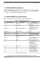
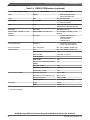
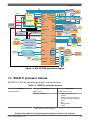
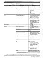
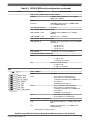
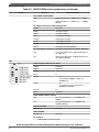
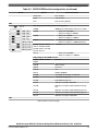
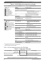
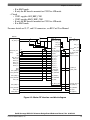
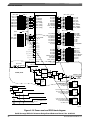
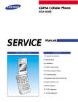
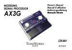
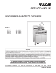
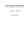
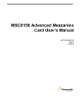
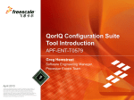
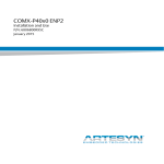
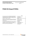
QorIQ Qonverge BSC9131 Reference
Design Board Reference Manual
Document Number: BSC9131RDBRM
Rev 0, 06/2014
QorIQ Qonverge BSC9131 Reference Design Board Reference Manual, Rev. 0, 06/2014
2
Freescale Semiconductor, Inc.
Contents
Section number
Title
Page
Chapter 1
Introduction
1.1
Related documentation....................................................................................................................................................7
1.2
Acronyms and abbreviations...........................................................................................................................................8
1.3
Bit and Byte definitions.................................................................................................................................................. 10
1.4
BSC9131RDB board features......................................................................................................................................... 11
1.5
BSC9131RDB board specifications................................................................................................................................11
1.6
BSC9131 processor features........................................................................................................................................... 13
Chapter 2
Power Supply
2.1
Primary power supply..................................................................................................................................................... 18
2.2
BSC9131RDB power supply structure........................................................................................................................... 19
Chapter 3
Working environment
3.1
Hardware kit contents..................................................................................................................................................... 21
3.2
Switch default settings.................................................................................................................................................... 22
3.3
Jumper default settings................................................................................................................................................... 29
3.4
Connector default settings...............................................................................................................................................32
3.5
Push buttons.................................................................................................................................................................... 35
3.6
LED lights.......................................................................................................................................................................36
3.7
Getting started.................................................................................................................................................................37
Chapter 4
Functional Description
4.1
Clocking..........................................................................................................................................................................41
4.2
Platform speed (CCB) clock........................................................................................................................................... 42
4.3
Core clock ...................................................................................................................................................................... 43
4.4
DSP clock........................................................................................................................................................................43
4.5
DDR clock...................................................................................................................................................................... 44
QorIQ Qonverge BSC9131 Reference Design Board Reference Manual, Rev. 0, 06/2014
Freescale Semiconductor, Inc.
3
Section number
Title
Page
4.6
I2C...................................................................................................................................................................................46
4.7
uSIM interface................................................................................................................................................................ 47
4.8
TDM interface (SLIC/SLAC)......................................................................................................................................... 48
4.9
GPS module.................................................................................................................................................................... 49
4.10 BSC9131RDB USB........................................................................................................................................................ 49
4.11 Ethernet 1588 clock........................................................................................................................................................ 50
4.12 Antenna interface............................................................................................................................................................ 52
4.13 Maxim PHY.................................................................................................................................................................... 52
4.14 ADI................................................................................................................................................................................. 52
4.15 Reset and initialization....................................................................................................................................................53
4.16 Power-On-Reset sequence.............................................................................................................................................. 57
4.17 JTAG COP, JTAG/EOnCE, and UART......................................................................................................................... 57
4.18 Ethernet........................................................................................................................................................................... 59
4.19 SPI...................................................................................................................................................................................61
QorIQ Qonverge BSC9131 Reference Design Board Reference Manual, Rev. 0, 06/2014
4
Freescale Semiconductor, Inc.
Chapter 1
Introduction
BSC9131 Reference Design Board (RDB) is an application development system that
verifies the QorIQ Qonverge BSC9131 processor device operations and provides a high
level of system performance characterization.
BSC9131RDB reflects the design-focus of most customer applications such as electric,
circuit, and logic testing. BSC9131RDB enables the simultaneous operations and
verification of interfaces and protocols found in specific market applications.
BSC9131 is a highly integrated device that targets evolving Microcell, Picocell, and
Enterprise-Femto base station market sub-segments. The BSC9131 device combines
Power Architecture® e500 and DSP StarCore SC3850 core technologies with MAPLEB2F baseband acceleration processing elements. Together they address the need for a
high performance, low cost, and integrated solution that handles all the required
processing layers without the need of an external device (except for an RF transceiver or,
in a Micro base station configuration, a host device that handles the L3/L4 and handover
between sectors).
The BSC9131RDB board support package (BSP) is built using a Linux operating system.
Developers using BSC9131RDB onboard resources and debugging devices can perform
the following:
•
•
•
•
Upload and run code
Set breakpoints
Display memory and registers
Connect proprietary hardware for incorporation into a target system using BSC9131
as a processor
• Use BSC9131RDB as a demonstration tool, that is, the developer application
software is programmed into flash memory and run in exhibitions.
A software application developed for the BSC9131 processor can run as a bare bones
operation or with various input/output data streams; for example, GETH connections.
Results can be analyzed using the CodeWarrior debugger or with other methods that
directly analyze I/O data streams.
QorIQ Qonverge BSC9131 Reference Design Board Reference Manual, Rev. 0, 06/2014
Freescale Semiconductor, Inc.
5
Figure 1-1 shows the component side of the BSC9131RDB board.
Figure 1-1. BSC9131RDB board: Component side
QorIQ Qonverge BSC9131 Reference Design Board Reference Manual, Rev. 0, 06/2014
6
Freescale Semiconductor, Inc.
Chapter 1 Introduction
Figure 1-2. BSC9131RDB board: Print side
1.1 Related documentation
The BSC9131RDB Quick Start Guide (QS) is required reading. A media copy is included
in the Hardware Getting Started kit.
The table below lists and explains the additional documents that you can refer to, for
more information about BSC9131RDB.
QorIQ Qonverge BSC9131 Reference Design Board Reference Manual, Rev. 0, 06/2014
Freescale Semiconductor, Inc.
7
Acronyms and abbreviations
Some of the documents listed below may be available only under a non-disclosure
agreement (NDA). To request access to these documents, contact your local field
applications engineer or sales representative.
Table 1-1. Related documentation
Document
Description
BSC9131 QorIQ Qonverge Multicore Baseband Processor
Data sheet
Provides information about Pin assignments, Electrical,
characteristics, Hardware design, considerations, Package
information, and Ordering information.
BSC9131 QorIQ Qonverge Multicore Baseband Processor
Reference Manual
Provides a detailed description about BSC9131 QorIQ
Qonverge multicore processor, and features, such as memory
map, serial interfaces, power supply, chip features, and clock
information.
1.2 Acronyms and abbreviations
The table below lists and explains the acronyms used in this document.
Table 1-2. Acronyms and abbreviations
Term
Description
ADI
Analog Device Interface
ADM
Address Data MUX
AGC
Antennas Gain Command
AIC
Antenna Interface Controller
ANT
Antenna
CFG
Configuration
CLK
Clock
CLKIN
Clock Input; interchangeable with SYSCLK
CON
Connector
COP
Common On-Chip Processor
CPU
Central Processing Unit
CRC
Cyclical Redundancy Checking
CS
Chip Select
CTS
Clear To Send
DDR
Double Data Rate
DIP
Dual-in-Line Package (switches)
DMA
Directy Memory Access
DPU
Debug and Profiling Unit
DSP
Data Signal Processing
dTSEC
Data 3-speed Ethernet Controller
DUART
Dual Universal Asynchronous Receiver/Transmitter
Table continues on the next page...
QorIQ Qonverge BSC9131 Reference Design Board Reference Manual, Rev. 0, 06/2014
8
Freescale Semiconductor, Inc.
Chapter 1 Introduction
Table 1-2. Acronyms and abbreviations (continued)
Term
Description
DUT
Device-under-Test
ECC
Error Detection and Correction
EEPROM
Electrical Erasable Programmable Memory
EOnCE
Enhanced On Chip Emulator
EPIC
Enhanced Programmable Interrupt Controller
eSDHC
Enhanced Secure Digital Host Controller
eSPI
Enhanced Serial Peripheral Interface
ETH
Ethernet
eTSEC
Enhanced 3-speed Ethernet Controller
FDD
Frequency-division Duplexing
FPGA
Field-Programmable Gate Array
GETH
Giga Ethernet
GPIO
General Purpose In/Out
GPS
Global Positioning System
GSM
Global System for Mobile Communications
HRESET
Hard Reset
I2C
Inter-Integrated Circuit Multi-master Serial Computer Bus
IDE
Integrated Development Environment
IFC
Integrated Flash Memory Controller
IO
Input/Output
JTAG
Joint Test Access Group (IEEE® Std. 1149.1™)
LED (also LD & D)
Light-emitting Diode
LSB
Least Significant Bit
LTE
Long Term Evolution
MAPLE
Multi Accelerator Platform Engine
MISO
Multiple Input, Single Output
MMU
Memory Management Unit
MSB
Most Significant Bit
MUX
Multiplex
OTG
On-the-Go Protocol
PD
Presence Detect
PEX
PCI Express (PCIe)
PHY
Physical Layer
PIC
Programmable Interrupt Controller
PLAT
Platform
PLL
Phased Lock Loop
PORESET
Power-on-Reset
POVDD
Parameter Operating Voltage
PS
Power Supply
Table continues on the next page...
QorIQ Qonverge BSC9131 Reference Design Board Reference Manual, Rev. 0, 06/2014
Freescale Semiconductor, Inc.
9
Bit and Byte definitions
Table 1-2. Acronyms and abbreviations (continued)
Term
Description
RC
Root Complex
RCW
Reset Configuration Word
RDB
Reference Design Board
RF
Radio Frequency
RGMII
Reduced General Media Independent Interface
ROM
Read-only Memory
RTC
Real Time Clock
SD
Secure Digital
SerDes or SRDS
Serializer/Deserializer
High Speed Serial Communication Lines; e.g. PEX
SIM
Subscriber Identity Module
SLAC
Subscriber Line Audio Processing Circuit
SLIC
Subscriber Line Interface Circuit
SPI
Serial Peripheral Interface
SYS
System
SYSCLK
System Clock; interchangeable with CLKIN
TDD
Time Division Duplex
TDM
Time-division multiplexing
UART
Universal Asynchronous Receiver/Transmitter
UMTS
Universal Mobile Telecommunications System
USB
Universal Serial Bus
uSIM
UMTS Subscriber Identity Module
VCC
Voltage at various common power supply terminals
WCDMA
Wideband Code-Division Multiple Access
XVDD
Phased Lock Loop Voltage
1.3 Bit and Byte definitions
Table 1-3. Bit and Byte terminology
Bit
Byte
Binary digit with a single binary value, 1 or 0.
A unit of data, eight binary units long that is used as a
measure of computer processor storage and real and virtual
Commonly used for measuring the amount of data transferred
memory.
in one second between two telecommunication points.
Kbps = Kbit/s
Kilobit per second (1 Kbps =
1000 bits)
Kbyte = KB = KByte
1 Kilobyte = 1024 bytes
Mbps = Mbit/s
Megabit per second (1 Mbps
= 1,000,000 bits)
Mbyte = MB = MByte
1 Megabyte = ~ 1,000,000
bytes
Gbps = Gbit/s
Gigabit per second (1 Gbps = Gbyte = GB = GByte
"billions of bits")
1 Gigabyte = ~ 1 billion bytes
QorIQ Qonverge BSC9131 Reference Design Board Reference Manual, Rev. 0, 06/2014
10
Freescale Semiconductor, Inc.
Chapter 1 Introduction
1.4 BSC9131RDB board features
The BSC9131RDB supports a BSC9131 processor. The board has a 1.0V core voltage
and runs at 800/1000 MHz for each core. The 1.5V DDR runs at a 400/500MHz clock
rate. Figure 1-3 shows the BSC9131RDB block diagram.
1.5 BSC9131RDB board specifications
The following table list the various features of BSC9131RDB board.
Table 1-4. BSC9131RDB features
BSC9131RDB feature
Specification
Description
Processor
BSC9131
Internal clock runs at 800/1000 MHz @
1.0V core voltage
Memory
DDR3 and Bus
• 8-bit, 1GB, 32-bit, 78-ball FPGA,
DDR3 devices (4)
• Device data rate up to 800 Mbp/s
IFC Interface
Buffered Memory: NAND flash
• 8-bit port size in socket
• 128 MB small page
• 3.3V
ANT1 and ANT2
ADI1 ADI2 and MAX
RF Connector2
ANT3
ADI3
RF Connector1
GETH Transceiver
dTSEC
RCW
I2C controlled DIP-switches or IO
Expander
DUART
UART0
DUART
UART1
I2C
I2C0
•
•
•
•
•
•
USB
OTG and PHY
• USB OTG (microAB connector)
• PHY - USB SMSC3315
eSPI1
SPI
• Spansion SPI FLASH CS0
• Control RF Card2 CS3
• SLIC/SLAC Le88266DLC CS1
eSPI2
SPI
• Control RF Card1 CS0, CS1
• Control RF Card2 CS2, CS3
• dTSEC1 - RGMII VCS8641XKO
• dTSEC2 - RGMII VCS8641XKO
Onboard DIP-switches
• Dedicated D-type RS232 connector
• Muxed with EOnCE pins
GPS LEA-6T-0 module transfer data
256 KB boot EEPROM
External connector for external host
IO expander for RCW
Thermal monitor
GPS LEA-6T-0 module control
Control RF cards 1 and 2
Table continues on the next page...
QorIQ Qonverge BSC9131 Reference Design Board Reference Manual, Rev. 0, 06/2014
Freescale Semiconductor, Inc.
11
BSC9131RDB board specifications
Table 1-4. BSC9131RDB features (continued)
BSC9131RDB feature
Specification
Description
JTAG
EOnCE
JTAG
COP
Onboard COP header
JTAG_MODE
JTAG_MODE
Device controlled through COP or EOnCE
or a combination thereof
1588
1588
Support 1588 optional input CLK 66 MHz/
100 MHz/GPS10 MHz/ANT Ref CLK
SIM CARD
SIM CARD
SIM CARD 1.8V/3.3V
SYS_CLK/RTC_CLK/DSP_in_CLK/
DDRCLK
66MHz/100MHz selectable clock
SYS_CLK/RTC_CLK/DSP_in_CLK/
DDRCLK
Power Up
Power-ON
• Remote Power-ON used
HRESET_REQ REG
• Power-ON switch
• HRESET switch
Power Requirements
Standalone
• Independent host; PEX RC
• 12V @ 5.5A external DC PS
Power Consumption
Cores and Platform
Max. 5W at 1000MHz @VDD=1.0V
Supply Voltages
Cores
Max. 5W at 1000MHz@VDD=1.0V
Core, DDR, DSP, PLAT, RF - PLLs
1.0 V
Ethernet LVDD
2.5V; subject to protocol
Local bus BVDD
3.3
DDR3 GVDD
1.5V
Secure Fuse Programming Overdrive
POVDD
1.5V
USB, SPI1, CVDD
3.3V
ADI Interface SPI2 - XVDD
1.8V/3.3V
MAX Interface - RVDD
1.5V
Environmental Conditions
Operating Temperature
Operating Junction Temperature
Dimensions
• Onboard EOnCE header
• Muxed with UART0 pins
0OC to 70OC
(Tj)1
0OC to 105° C
Storage Temperature
-25OC to 85OC
Relative Humidity
5% to 90% (non-condensing)
Length
170 mm
Width
170 mm
1. Processor technology
QorIQ Qonverge BSC9131 Reference Design Board Reference Manual, Rev. 0, 06/2014
12
Freescale Semiconductor, Inc.
Chapter 1 Introduction
5V_RF
XVDD
VCC3.3V
ANT1
ADD 0x51
CS3
CS2
CS3
RF Card2
CS0
CS1
RF Card1
ANT2
SPANSION
SPI FLASH
CS0
AVDD-CORE/DDR/DSP/
PLAT/RF
SPI2
1588_CLK_IN
1588CLK
GPS10MHZ CLK
GPS_1PPS_OUTPUT
Thermal
monitor
UART1
USB PHY USB3315
128M x8 Bit NAND
Flash Memory
25 Mhz
CLK
USB Interface
2G DDR3 1.5V
2G DDR3 1.5V
MT41J256M8HX-15E
IT:D
2G DDR3 1.5V
MT41J256M8HX-15E
IT:D
2G DDR3 1.5VIT:D
MT41J256M8HX-15E
MT41J256M8HX-15E IT:D
SPI1_CS1
RGMII PHY
RGMII2
Level
translator
3.3/1.8V
Le88266DLC
SLIC/SLAC
2.048Mhz
CLK
I2C IOExpander
Power Up
Reset
COP
connector
UART0/
EONCE
EONCE
connector
UART Transceiver
9PIN D Type
connector
66Mhz
CLK
DSP_CLK
100Mhz
CLK
DDR_CLK
BSC9131
DDR
SPD
HRESET
SYS_CLK
SIM Interface
5V to
2.5V
RJ11
connector
Config
signals
COP
RGMII1
5V to
1.5V/3.3V
Select
3.3V/1.5V
IFC
VSC8641XKO
RGMII
PHY
VSC8641XKO
SIM
CARD
5V to
DDR 1.5V
I2C0
I2C ADDRESS 0X42
GPS-LEA-6T-0
5V to
3.3V
I2C
External
connector
I2C0
12V
Input
connector
Regulator
DIP
SWITCH
Micro USB
CONN
1588_TRIG_IN
SPI1
BUS
TDM
SPI1
12V to 5V
12V to 5V
Regulator
5V to
1.5V
DDR
Boot seq
GPS
ANTENNA
5V to
CORE
regulator
VDD/VDDC
MAX
RVDD/POVDD1
ADI_CLK
BVDD/CVDD
GVDD
MAX_CLK
XVDD
ANT3
LVDD
ADD 0x53
5V to
3.3V/
1.8V
RTC_CLK
1588CLK
Figure 1-3. BSC9131RDB board block diagram
1.6 BSC9131 processor features
The BSC9131 SoC has the following features and specifications:
Table 1-5. BSC9131 processor features
Feature
Power Architecture
Specification
e500 Processor
e500 Core Subsystem
Description
256 KB shared L2 cache
• 32KB L1 instruction cache
(ICache)
• 32KB L1 data cache (DCache)
• 512 KB L2 cache/L2 memory/L2
stash
• PIC
• Debug support
• Timers
Table continues on the next page...
QorIQ Qonverge BSC9131 Reference Design Board Reference Manual, Rev. 0, 06/2014
Freescale Semiconductor, Inc.
13
BSC9131 processor features
Table 1-5. BSC9131 processor features (continued)
Feature
StarCore
Specification
SC3850 DSP Processor
Description
512KB private L2 cache
SC3850 DSP Subsystem
• 32 KB 8-way L1 ICache
• 32 KB 8-way L1 DCache
• 256 KB 8-way L2 unified I/DCache
(M2 memory)
• MMU
• EPIC
• DPU
• Two 32-bit timers
MAPLE
Femto Base Station Baseband
Processing (MAPLE-B2F)
• Multi-standard baseband algorithm
accelerator for channel decoding/
encoding, Fourier transforms,
UMTS chip rate processing, LTE
UP/DL channel processing, and
CRC algorithms
• Accelerators for convolution,
filtering, turbo encoding/decoding,
Viterbi decoding, chip rate
processing, and matrix inversion
operations
Security Engine
-
• Dedicated
• Trusted boot
Interfaces
DDR3/3L Memory Interface
• 32-bit data width without ECC
• 16-bit with ECC
• Up to 400 MHz clock/800 MHz
data rate
DMA Controller
OCN DMA with four bi-directional
channels
Gigabit Ethernet Controllers (2)
• 3-speed
• Network acceleration including
IEEE 1588™ v2 hardware support
and virtualization (eTSEC)
• eTSEC 1 supports RGMII/RMII
• eTSEC 2 supports RGMII
USB 2.0
• High speed
• Host and device controller with
ULPI interface
eSDHC
-
AIC
Supports the following:
• 3 industry standard JESD207
• 3 custom ADI RF interfaces (two
dual port and one single port)
• 3 MAXIM MaxPHY serial
interfaces
ADI lanes support the following:
• full duplex FDD support
• half duplex TDD support
USIM
Facilitates the communication to SIM
cards or Eurochip pre-paid phone cards
Table continues on the next page...
QorIQ Qonverge BSC9131 Reference Design Board Reference Manual, Rev. 0, 06/2014
14
Freescale Semiconductor, Inc.
Chapter 1 Introduction
Table 1-5. BSC9131 processor features (continued)
Feature
Specification
Description
TDM
• One port
• 256 channels
DUART
Two controllers
eSPI
Four controllers
I2C
Two controllers
IFC
-
GPIO
Sixteen 32-bit timers
Figure 1-4 shows BSC9131 processor block diagram.
x4
StarCore
SC3850 DSP core
Power Architecture
e500 core
32-Kbyte
32-Kbyte
L1 D-cache L1 I-cache
32-Kbyte
32-Kbyte
L1 D-cache L1 I-cache
521-Kbyte
L2 cache
Coherency 256-Kbyte
L2 cache
module
32-bit DDR3/3L
memory
controller
MAPLE-B2F
baseband
accelerator
LTE/UMTS/WiMAX
RF interface:
parallel &
serial (maxPHY)
Multicore
fabric
4x eSPI
2x I2C
GPIO
Ethernet
DMA
Security
engine
4.4
USB 2.0
Secure boot
2x DUART
IEEE 1588TM
1GE
USIM
RMII/
RGMII
IFC
1GE
RGMII
eSDHC
2x PWM
BSC9131
TDM
Clocks/reset
Figure 1-4. BSC9131 processor block diagram
QorIQ Qonverge BSC9131 Reference Design Board Reference Manual, Rev. 0, 06/2014
Freescale Semiconductor, Inc.
15
BSC9131 processor features
QorIQ Qonverge BSC9131 Reference Design Board Reference Manual, Rev. 0, 06/2014
16
Freescale Semiconductor, Inc.
Chapter 2
Power Supply
The BSC9131RDB power distribution system (PDS) provides the voltage necessary to
operate the BSC9131 chip and peripheral board devices. Figure 2-1 shows the voltage rail
connections with BSC9131 power supply requirements. Figure 2-2 shows the DUT
power sequence.
QorIQ Qonverge BSC9131 Reference Design Board Reference Manual, Rev. 0, 06/2014
Freescale Semiconductor, Inc.
17
Primary power supply
U93
BSC9131
12V 5.5A Input
DUT_LVDD
LVDD
OVDD/ CVDD/ BVDD
CINCON ELECTRONICS [TR70A1211E11]
VCC_3_3
U50
DUT_GVDD
12V to 5V
GVDD DUT_POVDD
POVDD
RVDD
VDDC/VDD
U1
5V to 3.3V/1.8V
5V to 3.3V
OUT 3.3V - 3A
AD - ADP2118
EN
DUT_XVDD1_SEL
1'b0-3.3 V
1'b1-1.8 V
RF_CON 1
OUT 3.3V/1.8V - 3A
AD - ADP2118
U90
SW6[1]
DUT_XVDD VCC_3_3 VCC_5RF
U89
DUT_LVDD
DUT_XVDD1_SEL
OUT 5V - 6A
TI - PTH12050WAZ
DUT_XVDD
VCC_3_3
DUT_XVDD
XVDD
12V to 5V
Remote ON/OFF OUT 5V - 6A
TI - PTH12050WAZ
DUT_RVDD
DUT_VDD
VCC_5RF
U49
VCC_5
5V to 2.5V
OUT 2.5V - 3A
EN AD - ADP2118
J28 select
3.3/1.8V
open = 1.8V
Close = 3.3V
RF_CON 2
DUT_GVDD VTT_DDR VREF_DDR
U35
5V to DDR3 Power
Freescale MC34716EP
EN
DUT_POVDD
DUT_RVDD
U41
5V to 1.5V
Linear
EN
LTC3025
DUT_VDD
U91
5V to 1V
Linear LTC3616 - 6A
EN
PG
Power up reset
Figure 2-1. DUT power supply block diagram
VDDC/VDD
XVDD RVDD POVDD GVDD OVDD/CVDD/BVDD LVDD
Figure 2-2. DUT power sequence
QorIQ Qonverge BSC9131 Reference Design Board Reference Manual, Rev. 0, 06/2014
18
Freescale Semiconductor, Inc.
Chapter 2 Power Supply
2.1 Primary power supply
The standalone BSC9131RDB 66W power supply has a standard CE/UL-approved 12V/
5.5A.
2.2 BSC9131RDB power supply structure
The main BSC9131RDB power voltages are as follows:
Table 2-1. BSC9131RDB power voltages
Part location
Vendor
Part number
Function
Voltage
U1
Analog Devices
ADP2118
Peripherals
3.3
U35
Freescale Semiconductor
MC34716EP
DDR
1.5
U41
Linear
LTC3025
POVDD
1.5
U49
Texas Instruments
PTH12050WAZ
VCC_5RF
5.0
U50
Texas Instruments
PTH12050WAZ
VCC_5
5.0
U89
Analog Devices
ADP2118
XVDD
3.3/1.8 selected by J28.
U90
Analog Devices
ADP2118
eTSEC and Ethernet PHY
2.5
U91
Linear
LTC3616
Core/Platform
1.0
QorIQ Qonverge BSC9131 Reference Design Board Reference Manual, Rev. 0, 06/2014
Freescale Semiconductor, Inc.
19
BSC9131RDB power supply structure
QorIQ Qonverge BSC9131 Reference Design Board Reference Manual, Rev. 0, 06/2014
20
Freescale Semiconductor, Inc.
Chapter 3
Working environment
The BSC9131RDB has a standalone working environment, powered by an external 12V
PS (included in kit) through connector P4.
3.1 Hardware kit contents
This section lists hardware kit contents of the BSC9131RDB board.
Table 3-1. BSC9131RDB hardware kit inventory
Hardware kit inventory
1. BSC9131RDB board (1)
1
2. Ethernet Cable (1)
3. Telephone RJ11 Cable (1)
4. Antenna Active GPS (1)
QorIQ Qonverge BSC9131 Reference Design Board Reference Manual, Rev. 0, 06/2014
Freescale Semiconductor, Inc.
21
Switch default settings
Table 3-1. BSC9131RDB hardware kit inventory
Hardware kit inventory
5. 15cm u-USBA MALE to USBA
FEMALE cable (1)
6. RS 232 SERIAL, DB9 MALE to
USB A MALE cable (1)
7. RF Spacer Parts
• Spacer 16mm (8)
• Screws (16)
8. Power Supply (1)
9. Power Cord
10. Universal AC Plug Adaptor
The printed matter (not included in the above table) includes:
•
•
•
•
QorIQ Qonverge BSC9131 Reference Design Board Quick Start Guide
Freescale Warranty Card: 920-75133
Safety Notice: 926-75254
Contact Information Sheet: 920-90570-00
QorIQ Qonverge BSC9131 Reference Design Board Reference Manual, Rev. 0, 06/2014
22
Freescale Semiconductor, Inc.
Chapter 3 Working environment
3.2 Switch default settings
Table 3-2 shows the default DIP-switch positions to establish the BSC9131RDB clock
domains. The default settings are for general use. If using a board support package (BSP),
then refer to the BSP document.
NOTE
Ensure DIP-switches are set according to the default values.
Table 3-2. BSC9131RDB clock domains
Clock Domain
Schematic Net
Test Point
Expected Value
Remarks
SYS CLK DUT_SYSCLK DUT_SYSCLK
U45.4
66.66 MHz
J16 selects 66.66 or 100MHz.
DUT DDR CLK PLL
DDRCLK
U46.4
66.66 MHz
J12 selects 66.66 or 100MHz.
RTC CLK PLL
RTCCLK
U44.4
66.66 MHz
J16 selects 66.66 or 100MHz.
DSP_CLK
DSPCLK
U47.4
66.66 MHz
J17 selects 66.66 or 100MHz.
1588_CLK
1588_SYSCLK
U43.4
66.66 MHz
J16 selects 66.66 or 100MHz.
GPS_10MHz_CLK
U101.10
-
10MHz from GPS module.
CON2_XCVR_REF
U101.8
-
Clock rate from RF card J6.
CON1_XCVR_REF
U101.4
-
Clock rate from RF card J9.
Figure 3-1 shows BSC9131RDB DIP-switch locations.
QorIQ Qonverge BSC9131 Reference Design Board Reference Manual, Rev. 0, 06/2014
Freescale Semiconductor, Inc.
23
Switch default settings
Figure 3-1. BSC9131RDB DIP-switch locations
Table 3-3 explains BSC9131RDB switch settings.
NOTE
User can choose the switch configuration values between 66.66
and 100 MHz.
Table 3-3. BSC9131RDB switch configurations
Switch
Options
Recommendations
SW1
SYS_PLL[0:2]: CCB Clock PLL Ratio
3'b000 4:1
-
3'b001 5:1
If 100MHz clock select (CS) then CCB = 500MHz
3'b010 6:1
If 66.66MHz CS then CCB = 400MHz [Default]
3'b011 8:1
Reserved
3'b100 10:1
Reserved
3'b101 12:1
Reserved
3'b110
PLL Bypass Functional Mode; Reserved
3'b111
PLL Bypass Burn-in Mode; Reserved
Table continues on the next page...
QorIQ Qonverge BSC9131 Reference Design Board Reference Manual, Rev. 0, 06/2014
24
Freescale Semiconductor, Inc.
Chapter 3 Working environment
Table 3-3. BSC9131RDB switch configurations (continued)
Switch
Options
Recommendations
DDR_PLL[0:1]: DDR Complex Clock PLL Ratio
2'b00 8:1
If 100MHz CS then DDR block clock = 800MHz
(DDR clock = 400MHz)
2'b01 10:1
-
2'b10 12:1
If 66.66MHz CS then data rate = 800MHz (DDR
clock = 400MHz) [Default]
2'b11 Synchronous Mode
Reserved
DDR_SPEED0: DDR Complex Speed0
DDR_SPEED0 - '0' PA
If 100MHz CS then DDR data rate < 967MHz
[Default]
DDR_SPEED0 - '1' PA
DDR data rate > / = 967MHz
DDR_SPEED1: DDR Complex Speed1
DDR_SPEED1 '0'
[Default] If one of the following is chosen then DDR1
should be 0:
• cfg_ddr_pll = 8
• cfg_ddr_pll = 10
• cfg_ddr_pll = 12
DDR_SPEED1 '1'
If cfg_ddr_pll = 12 is chosen then DDR1 = 1
FLASH_MODE: NAND FLASH Mode
1'b0
Bad block indicator is found,
• on page 0; and,
• on last page of each block
1'b1
Bad block indicator is found,
• on page 0; and,
• on page 1 of each block
SW2
BOOT_SEQ[0:1]
2'b00
Reserved
2'b01
• Uses normal I2C addressing mode
• Boot sequencer is enabled and loads
configuration information from a ROM on the
I2C1 interface
• Valid ROM must be present
2'b10
• Uses extended I2C addressing mode
• Boot sequencer is enabled and loads
configuration information from a ROM on the
I2C1 interface
• Valid ROM must be present
2'b11
• Boot sequencer is disabled
• No I2C ROM is accessed [Default]
PLATE_SPEED: Platform Speed
1'b0
Platform clock frequency > / = 167MHz and < 320
MHz
1'b1
Platform clock frequency > / = to 320MHz and<
601MHz [Default]
Table continues on the next page...
QorIQ Qonverge BSC9131 Reference Design Board Reference Manual, Rev. 0, 06/2014
Freescale Semiconductor, Inc.
25
Switch default settings
Table 3-3. BSC9131RDB switch configurations (continued)
Switch
Options
Recommendations
SYS_SPEED: System Speed
1'b0
SYSCLK frequency is > 33MHz and < / = 65MHz
1'b1
SYSCLK frequency is > 65MHz and < / = 133MHz
[Default]
IFC_PB[0:2]: IFC Pages Per Block Configuration
3'b000
Reserved
3'b001
2K pages per block
3'b010
1K pages per block
3'b011
512-bit pages per block
3'b100
256-bit pages per block
3'b101
128-bit pages per block
3'b110
64-bit pages per block
3'b111
32 bit pages per block [Default]
IFC_ADM_MODE: IFC Address Shift Mode Configuration for (NOR FLASH Only)
1'b0
Lower order address bits are MUXed with data on
IFC_AD[0:15]
1'b1
Higher order address bits are MUXed with data on
IFC_AD[0:15] [Default]
SW3
CORE_PLL[0:2]: e500 Core PLL Ratios
3'b000
Reserved
3'b001
Reserved
3'b010
1:1
3'b011
3:2
3'b100
• 2:1
• Core frequency 800MHz = 400 x 2 for
66.66MHz CS
3'b101
• 5:2
• Core frequency 1GHz = 400 x 5/2 for
66.66MHz CS [Default]
3'b110
3:1
3'b111
Reserved
CORE_SPEED: e500 Core Speed
1'b0
Core clock frequency is > / = to 333MHz and <
500MHz
1'b1
Core clock frequency is > / = to 500MHz and <
1001MHz [Default]
DDR PLL BACKUP
[Default = 1]
Reserved
DDR H/F MODE
[Default = 0]
Reserved
IFC_ECC[0:1]
Table continues on the next page...
QorIQ Qonverge BSC9131 Reference Design Board Reference Manual, Rev. 0, 06/2014
26
Freescale Semiconductor, Inc.
Chapter 3 Working environment
Table 3-3. BSC9131RDB switch configurations (continued)
Switch
Options
Recommendations
2'b00, 2'b01
ECC disabled
2'b10
4-bit correction
2'b11
8-bit correction [Default]
SW4
DSP_PLL[0:3]: DSP Subsystem PLL Configuration
4'b0000
[400MHz] Use COP platform frequency as CLKIN
4'b0001
• DSP_CLK = 66.66MHz
• DSP core frequency =800MHz
4'b0010
• DSP_CLK = 100MHz
• DSP core frequency = 800MHz
4'b0011
• DSP_CLK = 100MHz
• DSP core frequency = 1000MHz [Default]
4'b0100, 4'b0101, 4'b0110,
4'b0111, 4'b1000, 4'b1001,
4'b1010, 4'b1011, 4'b1100,
4'b1101, 4'b1110
Reserved
4'b1111
• DSP_CLK = 66.66MHz
• DSP core frequency = 1000MHz
ROM_LOC[0:3]: Boot ROM Location
4'b0000, 4'b0001, 4'b0010,
4'b0011
Reserved
4'b0100
DDR controller1
4'b0101
Reserved
4'b0110
SPI
4'b0111
eSDHC (SD/MMC)
4'b1000
8-bit NAND-512-bit page size [Default]
4'b1001
8-bit NAND-2K page size
4'b1010
8-bit NAND-4K page size
4'b1011
RDB does not support 8-bit NOR
4'b1100
RDB does not support 16-bit NAND-512-bit page
size
4'b1101
RDB does not support 16-bit NAND-2K page size
4'b1110
RDB does not support 16-bit NAND-4K page size
4'b1111
RDB does not support 16-bit NOR
SW5
Table continues on the next page...
QorIQ Qonverge BSC9131 Reference Design Board Reference Manual, Rev. 0, 06/2014
Freescale Semiconductor, Inc.
27
Switch default settings
Table 3-3. BSC9131RDB switch configurations (continued)
Switch
Options
Recommendations
SVR[0:1]
Not Used: Reserved
ENG_USE1
Not Used: Reserved
CPU_BOOT: CPU Boot Configuration
1'b0
• CPU boot hold-off mode.
• e500 core is prevented from booting until
configured by an external master
1'b1
e500 core is allowed to boot without waiting for
configuration by an external master [Default]
SRDS_RFCLK
Not Used: Reserved
IO_PORTS[0:1]
Not Used: Reserved
IFC_ADM_MODE_P1010
Not Used: Reserved
SW62
DUT_XVDD1_SEL
• I/O voltage status for XVDD1/2 supplies.
• XVDD1/2 reflect the state of XVDDx_VSEL
input pins
1'b0
• 3.3V
• J28 should be short
1'b1
• 1.8V
• J28 should be open [Default]
BSC9131_RCW
1'b0
P1010 in socket
1'b1
BSC9131 in socket
CFG_JTAG_MODE[0:1]
-
CFG_JTAG_MODE[0:1] =0 0
Uses IFC_WP_B and IFC_BCTL signals
CFG_JTAG_MODE[0:1] =0 1
Uses IFC_WP_B and IFC_BCTL signals
CFG_JTAG_MODE[0:1] =1 0
Uses IFC_WP_B and IFC_BCTL signals
CFG_JTAG_MODE[:01] =1 1
Uses DSP_TDI, DSP_TDO and DSP_TRST signals
[Default]
DSP_EE0
1'b0
Normal operation [Default]
1'b1
Titanium debug request (DSP CORE STOP)
CFG_SRDS_REFCLK
Internal use only
1. Unsupported as a boot source in secure boot mode.
2. Refer Configuration JTAG modes table.
Table 3-4 lists the configuration details of the JTAG Mode.
Table 3-4. Configuration JTAG modes
CFG_JTAG_MODE[0:1]
00
Power Architecture
DSP Architecture
JTAG Available
JTAG Available
Yes
No
JTAG Topology
Access Power Architecture and DSP domains
using Power Architecture JTAG port J3.
Table continues on the next page...
QorIQ Qonverge BSC9131 Reference Design Board Reference Manual, Rev. 0, 06/2014
28
Freescale Semiconductor, Inc.
Chapter 3 Working environment
Table 3-4. Configuration JTAG modes (continued)
CFG_JTAG_MODE[0:1]
Power Architecture
DSP Architecture
JTAG Available
JTAG Available
JTAG Topology
01
No
Access DSP domain using Power Architecture
JTAG port J3.
10
No
Access Power Architecture domain using
Power Architecture JTAG port J3.
11
Yes
• Access Power Architecture domain using
Power Architecture JTAG J3.
• Access DSP domain using DSP JTAG
J2.
The following table shows different clock options and the corresponding DIP-switches
setting.
Table 3-5. Platform, PPC Core, DSP Core, and DDR SPEED for
SYS_CLK 66.66MHz and 100MHz
SYS_CLK
66.66MHz
100MHz
100MHz
CCB (Platform)
400MHz
SW1[1,2,3] =
0,1,0
400MHz
SW1[1,2,3] =
0,0,0
500MHz
SW1[1,2,3] =
0,0,1
PPC Core
800MHz
SW3[1,2,3] =
1,0,0
800MHz
SW3[1,2,3] =
1,0,0
1000MHz
SW3[1,2,3] =
1,0,1
DSP Core
800MHz
SW4[1,2,3,4] =
0,0,0,1
800MHz
SW4[1,2,3,4] =
0,0,0,1
1000MHz
SW4[1,2,3,4] =
0,0,1,1
DDR
800MHz
SW1[4,5,6,7] =
1,0,0,1
800MHz
SW1[4,5,6,7] =
1,0,0,1
800MHz
SW1[4,5,6,7] =
0,0,0,0
3.3 Jumper default settings
Table 3-6 lists the factory default 3-Pin jumper settings for the BSC9131RDB board. The
default settings are for general use. If using a BSP, then refer to the BSP document.
Table 3-6. BSC9131RDB 3-Pin jumper default settings
Jumper
Purpose
Close State 1,2
Close State 2,3
Remarks
J1
UART1_ CTS/COP_SRST/SIM_PD
COP_SRST
SIM_PD
[Default] 1, 2
J5
RF Interface2 CNT2 Select
ANT2_AGC to PIN33
ANT2_AGC to
PIN90
[Default] 2, 3
J7
SPI1CS3/TCXO_PWM
RF2_CON SPI1CS3
RF2_CON
TCXO_PWM
[Default] 1, 2
J8
SPI1_MISO/CKSTP_IN
SPI1_MISO
CKSTP_IN
[Default] 1, 2
J10
RF Interface1 CNT2 Select
ANT3_AGC to PIN33
ANT3_AGC to
PIN90
[Default] 2, 3
Table continues on the next page...
QorIQ Qonverge BSC9131 Reference Design Board Reference Manual, Rev. 0, 06/2014
Freescale Semiconductor, Inc.
29
Jumper default settings
Table 3-6. BSC9131RDB 3-Pin jumper default settings (continued)
Jumper
J11
Purpose
PO_VDD1
Close State 1,2
GND
Close State 2,3
1.5V
Remarks
[Default] 2, 3
Table 3-7 lists the factory default 2-Pin jumper settings for the BSC9131RDB board.
Table 3-7. BSC9131RDB 2-Pin jumper default settings
Jumper
Purpose
Close State
Open State 2,3
Remarks
J12
DDR CLK
66MHz
100MHz
[Default] Close
J13
ADI/MAX_REF_CLK Input CLK from RF
CON
From RF CON1
From RF CON2
[Default] Close
J16
SYS CLK, RTC_CLK, 1588_CLK
66MHz
100MHz
[Default] Close
J17
DSP_CLK
66MHz
100MHz
[Default] Open
J18, J21
1588_CLK_IN Source
-
J18 and J21
SourceCON1_XC
VR_REF
J21
J18
Source
GPS_10MHz_CL
K
J18
J21
SourceCON2_XC
VR_REF
J18 and J21
-
Source J16
J19
Boot Sequence EEPROM Write Protect
Write Enable
Write Protect
[Default] Close
J20
SIM POWER Supply
1.8V
3.3V
[Default] Open
J22
REMOTE HRESET
HRESET Active
Normal Operation
[Default] Open
J23
REMOTE POWER-UP
RDB Power Down
Normal Operation
[Default] Open
J32
I2C Header
cable
cable
[Default] Open
J30
Switch Panel
-
-
-
Figure 3-2 shows the component side connector locations.
QorIQ Qonverge BSC9131 Reference Design Board Reference Manual, Rev. 0, 06/2014
30
Freescale Semiconductor, Inc.
Chapter 3 Working environment
J22
J23
J1
J5
J7
J10
J8
J11
J16
J12
Jumpers (J):21,18,20,19,17,13
Figure 3-2. BSC9131RDB component side view
Figure 3-3 shows the print side connector locations.
QorIQ Qonverge BSC9131 Reference Design Board Reference Manual, Rev. 0, 06/2014
Freescale Semiconductor, Inc.
31
Connector default settings
J28
J30
Figure 3-3. BSC9131RDB print side view
3.4 Connector default settings
The following table lists the factory default connector and socket settings for the
BSC9131RDB board. The default settings are for general use. If using the BSP, then refer
to the BSP document.
Table 3-8. BSC9131RDB connectors
Connector
Type
J2
ONCE
J3
COP
J4/J29
Bridge
Table continues on the next page...
QorIQ Qonverge BSC9131 Reference Design Board Reference Manual, Rev. 0, 06/2014
32
Freescale Semiconductor, Inc.
Chapter 3 Working environment
Table 3-8. BSC9131RDB connectors (continued)
Connector
Type
J14
SMA TSEC 1588 PULSE OUTPUT
J15
SMA TSEC 1588 PULSE INPUT
J25
9-PIN RS232
J26
RJ11 Telephone
J27
Micro-USB
J31
GPS Antenna
J32
Remote I2C RDB Control
P1
SIM Holder
P2, P3
ETH PHY
P4
12V Power
J6, J9
ADI/MAX RF Antenna Boards
The following figure shows the BSC9131RDB connector locations.
QorIQ Qonverge BSC9131 Reference Design Board Reference Manual, Rev. 0, 06/2014
Freescale Semiconductor, Inc.
33
Connector default settings
J9
J6
J4
J2
J32
J14
J3
J15
QorIQ Qonverge BSC9131 Reference Design Board Reference Manual, Rev. 0, 06/2014
34
Freescale Semiconductor, Inc.
Chapter 3 Working environment
P1
J25
J26
J27
J29
P2
P3
P4
J31
Figure 3-4. BSC9131RDB connector locations
3.5 Push buttons
Table 3-9 lists the functioning of the BSC9131RDB board push buttons.
Table 3-9. BSC9131RDB push buttons
Switch
Function
Description
SW7
DUT HRESET
[Default] ON: Assertion
SW8
Board Power-UP reset
[Default] ON: Assertion
QorIQ Qonverge BSC9131 Reference Design Board Reference Manual, Rev. 0, 06/2014
Freescale Semiconductor, Inc.
35
LED lights
Figure 3-5 shows the BSC9131RDB push button locations.
Figure 3-5. BSC9131RDB push buttons
3.6 LED lights
Table 3-10 lists the functioning of BSC9131RDB LED lights.
.
Table 3-10. BSC9131RDB LEDs
LED
D6
Color
GREEN
Name
LED ON
LED OFF
12V
POWER-IN 12V
-
D7
5V_HOT
5V to RDB
Board OFF
D8
DDR POWER-ON
DDR POWER-ON
-
D9
5V to RF Boards
5V to RF Boards
-
D10
CORE POWER ON
CORE POWER-ON
-
D11
EE1
DSP CORE STOP
DSP CORE RUN
D12
USB HALT
USB POWER HALT
USB POWER OK
Table continues on the next page...
QorIQ Qonverge BSC9131 Reference Design Board Reference Manual, Rev. 0, 06/2014
36
Freescale Semiconductor, Inc.
Chapter 3 Working environment
Table 3-10. BSC9131RDB LEDs (continued)
LED
Color
Name
LED ON
LED OFF
D13
USB VBUS
POWER USB ON
NO USB POWER
D14
READY
BSC9131 Ready
Not running OR JTAG DSP is connected
Figure 3-6 shows the BSC9131RDB LED locations.
Figure 3-6. BSC9131RDB LEDs
3.7 Getting started
The following section outlines the standalone activation of BSC9131RDB board.
Perform the following steps to ensure correct initial board power-up:
1. Verify that all hardware kit contents are present. See, "Hardware kit contents".
2. Establish the working environment for BSC9131RDB. See, "Working environment".
3. Check and verify the BSC9131RDB default switch settings. See, "Switch default
settings".
4. Check and verify the BSC9131RDB default jumper settings. See, "Jumper default
settings".
5. Follow the instructions to connect to the CodeWarrior USB TAP:
NOTE
Freescale CodeWarrior USB TAP enables CodeWarrior
software to work with BSC9131RDB. Align and connect as
instructed.
QorIQ Qonverge BSC9131 Reference Design Board Reference Manual, Rev. 0, 06/2014
Freescale Semiconductor, Inc.
37
Getting started
a. Align the red stripe of the CW USB-UTAP connector cable with Pin 1 of the
JTAG/COP 16-pin connector (J3).
Align red stripe
to J3 pin1
J3
Figure 3-7. CodeWarrior USB-UTAP
b. Plug the connector cable into J3 connector.
c. Check for completion of the reset sequence (D6-10) light.
6. Follow the instructions to assemble and connect the power supply.
a. Ensure the power supply is OFF.
b. Assemble 12V 5.5A power supply kit.
c. Connect the power supply to 12V connector (P4).
d. Plug the power cable into the wall outlet.
QorIQ Qonverge BSC9131 Reference Design Board Reference Manual, Rev. 0, 06/2014
38
Freescale Semiconductor, Inc.
Chapter 3 Working environment
P4
Figure 3-8. Power supply cable attached to P4 connector
7. Attach the following optional cables as per the requirement:
a. Connect RS-232 cable to J25.
b. Attach a telephone RJ11 cable to J26.
c. Connect USB MicA to MicB cable to J27.
d. Connect an ETHERNET cable at P2/P3.
QorIQ Qonverge BSC9131 Reference Design Board Reference Manual, Rev. 0, 06/2014
Freescale Semiconductor, Inc.
39
Getting started
J25
J26
J27
P2/3
Figure 3-9. Optional cables attached to BSC9131RDB board
QorIQ Qonverge BSC9131 Reference Design Board Reference Manual, Rev. 0, 06/2014
40
Freescale Semiconductor, Inc.
Chapter 4
Functional Description
This chapter describes BSC9131RDB clocking in general and as per specific clock types.
4.1 Clocking
Figure 4-1 shows BSC9131RDB clocking. The BSC9131RDB has two clock oscillators,
Y3/100MHz and Y4/66.66MHz. These clock oscillators drive to five MUX devices
which in turn, drive Y3 and Y4 to the following clocks: SYSCLK, RTCCLK,
TSEC_1588_CLK_IN, DDRCLK, and DSP_CLKIN.
Table 4-1. BSC9131RDB clocking
Jumper
Clock
J12
DDRCLK
J16
SYSCLK, RTCCLK, or
TSEC_1588_CLK_IN1
J17
DSP_CLKIN
Open
100MHz input clock
Closed
66.66MHz input clock
1. TSEC_1588_CLK_IN source may be J16, GPS Module 10MHz clock, or from either of the RF connectors.
QorIQ Qonverge BSC9131 Reference Design Board Reference Manual, Rev. 0, 06/2014
Freescale Semiconductor, Inc.
41
Platform speed (CCB) clock
ON ’0’ SW1
1K
SYS_PLL0
SYS_PLL1
SYS_PLL2
DDR_PLL0
DDR_PLL1
DDR_SPEED0
DDR_SPEED1
FLASH_MODE
1
2
3
4
5
6
7
8
ON ’0’ SW3
1
2
3
4
5
6
7
8
ON ’0’ SW4
U45
10K
1K
10K
1K
10K
1K
10K
1K
10K
1K
10K
1K
10K
IFC_AD[0]
CCB
PLL
IFC_AD[1]
IFC_AD[2]
IFC_AD[7]
CCB_CLK
1
SYSCLK
IFC_ADDR[24]
U44
DDR_CLK
UART_SOUT[0]
RTCCLK
J18
1K
1K
10K
1K
10K
IFC_AD[3]
CCB
PLL
IFC_AD[4]
IFC_AD[5]
CORE_CLK
1K
IFC_AD[6]
TSEC_1588_CLK_IN
1
2
3
4
5
6
7
8
U43
00
01
U101 10
11
S0
10K
1K
10K
10K
1K
EC_MDC
IFC_ADDR[16]
IFC_ADDR[17]
1
GPS_10MHz_CLK
0
CON2_XCVR_REF
J12
CON1_XCVR_REF
U46
J21
1
DDR CLK
1K
1K
0
S1
OFF ’1’
DSP_PLL0
DSP_PLL1
DSP_PLL2
DSP_PLL3
ROM_LOC0
ROM_LOC1
ROM_LOC2
ROM_LOC3
100MHz
Osc
0
DDR
PLL
IFC_ADDR[22]
Y3
1
OFF ’1’
CORE_PLL0
CORE_PLL1
CORE_PLL2
CORE_SPEED
DDR PLL BACKUP
DDR H/F MODE
IFC_ECC0
IFC_ECC1
J16
BSC9131
OFF ’1’
DSP
PLL
0
J17
U47
IFC_ADDR[18]
DSP_CLKIN
1
Y4
0
66.66MHz
Osc
Figure 4-1. BSC9131RDB clock subsystem block diagram
4.2 Platform speed (CCB) clock
The CCB is configured by SYS_PLL[0:2] through SW1[1:3] as shown in Figure 4-1. The
configuration signals IFC_AD[0:2] are sampled upon negation of BSC9131 HRESET.
Table 4-2. CCB - Clock PLL platform ratio
CFG function
Value
Ratio
Description
cfg_sys_pll[0:2]
3'b000
4:1
cfg_sys_pll[0:2]
3'b001
5:1
• Clock-in = 100MHz
• CCB = 500MHz
cfg_sys_pll[0:2]
3'b010
6:1
• Clock-in = 66.66MHz
• [Default] CCB =
400MHz
cfg_sys_pll[0:2]
3'b011
8:1
Reserved
cfg_sys_pll[0:2]
3'b100
10:1
Reserved
cfg_sys_pll[0:2]
3'b101
12:1
Reserved
cfg_sys_pll[0:2]
3'b110
• PLL Bypass Functional
Mode
• Reserved
cfg_sys_pll[0:2]
3'b111
• PLL Bypass Burn-in
Mode
• Reserved
QorIQ Qonverge BSC9131 Reference Design Board Reference Manual, Rev. 0, 06/2014
42
Freescale Semiconductor, Inc.
Chapter 4 Functional Description
4.3 Core clock
Figure 4-1 shows the core clock is configured by CORE_PLL[0:2], while the core speed
is configured through SW3[1:4]. The configuration signals IFC_AD[3:6] are sampled
upon negation of BSC9131 HRESET.
• CORE_PLL gets input clock through the platform clock by multiplying the platform
clock by the value of cfg_core_pll[0:2].
• CORE_SPEED sets the CORE PLL range to greater than 500MHz.
Table 4-3. CORE_PLL[0:2]: e500 core PLL ratios
CFG Function
Value
Ratio
Description
cfg_core_pll[0:2]
3'b000
Reserved
cfg_core_pll[0:2]
3'b001
Reserved
cfg_core_pll[0:2]
3'b010
1:1
-
cfg_core_pll[0:2]
3'b011
3:2
-
cfg_core_pll[0:2]
3'b100
2:1
Core frequency of 800MHz =
400 x 2 for clock in [default]
66.66MHz.
cfg_core_pll[0:2]
3'b101
5:2
SYSCLK 66.66MHz
cfg_core_pll[0:2]
3'b110
3:1
-
cfg_core_pll[0:2]
3'b111
-
cfg_core_speed
1'b0
-
• e500 core speed
• Reserved
Core clock frequency:
• > / = 333 MHz
• < 500 MHz
cfg_core_speed
1'b1
-
Core clock frequency:
• > / = 500 MHz
• [Default] < 1001 MHz
4.4 DSP clock
Figure 4-1 shows the DSP clock is configured by DSP_PLL[0:3] using SW4[1:4] . The
configuration signals EC_MDC and IFC_ADDR[16:18] are sampled upon BSC9131
HRESET negation.
QorIQ Qonverge BSC9131 Reference Design Board Reference Manual, Rev. 0, 06/2014
Freescale Semiconductor, Inc.
43
DDR clock
Table 4-4. DSP PLL: DSP subsystem PLL
configuration
CFG Function
Value
Ratio
Description
cfg_dsp_pll[0:3]
4'b0000
-
• 400MHz
• Use COP platform
frequency as CLKIN
cfg_dsp_pll[0:3]
4'b0001
-
• DSP_CLK = 66.66MHz
• [Default] DSP core
frequency =800MHz
cfg_dsp_pll[0:3]
4'b0010
-
• DSP_CLK = 100MHz
• DSP core frequency =
800MHz
cfg_dsp_pll[0:3]
4'b0011
-
• DSP_CLK = 100MHz
• DSP core frequency =
1000MHz
cfg_dsp_pll[0:3]
4'b0100, 4'b0101, 4'b0110,
4'b0111, 4'b1000, 4'b1001,
4'b1010, 4'b1011, 4'b1100,
4'b1101, 4'b1110
-
cfg_dsp_pll[0:3]
4'b1111
-
Reserved
• DSP_CLK = 66.66MHz
• DSP core frequency =
1000MHz
4.5 DDR clock
Figure 4-1 and Figure 4-2 shows the DDR clock is configured by DDR_PLL[0:1] and
DDR_SPEED[0:1] using SW1[4:7].
The DDR data rate is configured by cfg_ddr_pll [0:1], which are sampled at HRESET
negation by IFC_AD[7] for cfg_ddr_pll[0] and IFCADDR[22] for cfg_ddr_pll[1].
The 1 GB DDR is made of 2 Gbit 8-bit Micron (MT41J256M8HX-15EIT:D) DDR3
memory devices.
• DDR block gets DDR_CLK; a single ended input clock of either 66.66 or 100MHz.
• Input clock is selected by J12:
• Open: 100MHz
• Closed: 66.66MHz
QorIQ Qonverge BSC9131 Reference Design Board Reference Manual, Rev. 0, 06/2014
44
Freescale Semiconductor, Inc.
Chapter 4 Functional Description
VTT_DDR VREF_DDR
VCC_5
CORE_POWER_OK
DUT_GVDD
U35
IN
PG
U92
MDQ[0:7]
MDQS[0:3]
MDQS
MDM
MBA[0:2]
MBA[0:2]
MA[0:15]
MWE_B
MA[0:15]
MWE_B
10K
10K
10K
10K
MCAS_B
MCAS_B
MRAS_B
MRAS_B
IFC_ADDR[22]MCS0_B
MCS0_B
IFC_AD[7]
MCK
MCK_B
MCK
MODT0
MODT0
36.5
ohm
MDIC0
MDIC1
VREF_DDR
MVREF
U46
1
GVDD
Default 66MHz
Y3
DDR_CLK
DUT_GVDD
DUT_GVDD
MT41J256M8HX-15EIT:D
J12
66.66MHz
MCKE0
UART_SOUT[0] MCK_B
MT41J256M8HX-15EIT:D
DUT_GVDD
Y4
MCKE0
IFC_ADDR[24]
51
ohm
VTT_DDR
MT41J256M8HX-15EIT:D
1K
1K
1K
1K
MT41J256M8HX-15EIT:D
1
2
3
4
5
6
7
8
VTT_DDR
MDQS_B
MDM[0:3]
OFF ’1’
SYS_PLL0
SYS_PLL1
SYS_PLL2
DDR_PLL0
DDR_PLL1
DDR_SPEED0
DDR_SPEED1
FLASH_MODE
U97
MDQ[0:31]
MDQS[0:3]_B
ON ’0’ SW1
U95
U87
U93
DDR POWER
Freescale
MC34716EP
EN
BSC9131
51
ohm
GVDD
0
100MHz
Figure 4-2. DDR block diagram
Table 4-5. CFG pins
CFG pin name
Value
Ratio
Description
cfg_ddr_pll[0:1]
2'b00
8:1
DDR data rate =
ddr_clk_in(MHz) x 8 [Default].
cfg_ddr_pll[0:1]
2'b01
10:1
-
cfg_ddr_pll[0:1]
2'b10
12:1
cfg_ddr_pll[0:1]
2'b11
-
cfg_ddr_speed[0:1]
-
-
• DDR data rate =
ddr_clk_in(MHz) x 12
[Default]
• DDR Clock = 400MHz
Reserved
• Determines PLL
frequency range.
• For cfg_ddr_speed[0]:
• 0: DDR data rate
is less than 967
MHz.
• 1: DDR data rate
is greater than or
equal to 967 MHz.
• For cfg_ddr_speed[1]:
See Table 4-6.
QorIQ Qonverge BSC9131 Reference Design Board Reference Manual, Rev. 0, 06/2014
Freescale Semiconductor, Inc.
45
I2C
Table 4-6. cfg_ddr_speed[1] Settings
cfg_ddr_pll = 8
cfg_ddr_pll = 10
cfg_ddr_pll = 12
cfg_ddr_speed[0] = 0
1
1
1
cfg_ddr_speed[0] = 1
0
0
1
4.6 I2C
The BSC9131RDB uses the BSC9131 I2C1 bus. Table 4-7 describes the I2C devices and
their related addresses.
The I2C circuit has a 3-pin header (J32) with the following features:
• Connects to remote IO Expander devices for RCW.
• Writes init value to the IO Expander.
• Writes to the HRESET_REQ register, which automatically leads to board PowerOFF/ON.
• Performs Power-ON sequence
• Drives HRESET to low in order to load the RCW.
Table 4-7. I2C devices and addresses
Company
Analog Device
Part number
Address
ADT7461
0x4C
Retaled to
Note
Thermal Monitor
-
Boot Sequence
-
IO Expander RCW
For remote RCW
IO Expander RCW
For remote RCW
IO Expander RCW
For remote RCW
DDR SPD
-
Read 0x99
Write 0x98
ATMEL
AT24C512B-TH25-B
0x50
Read 0xA1
Write 0x50
Phillips
PCA9555PW
0x21
Read 0x43
Write 0x42
Phillips
PCA9555PW
0x23
Read 0x47
Write 0x46
Phillips
PCA9555PW
0x27
Read 0x4F
Write 0x4E
ST Microelectronics
M24C02
0x52
Read 0xA4
Write 0xA5
Table continues on the next page...
QorIQ Qonverge BSC9131 Reference Design Board Reference Manual, Rev. 0, 06/2014
46
Freescale Semiconductor, Inc.
Chapter 4 Functional Description
Table 4-7. I2C devices and addresses (continued)
Company
Part number
u-blox AG
LEA-6T-0
Address
0x42
Retaled to
Note
GPS
-
RF Connector1
See RF board for more
information.
RF Connector2
See RF board for more
information.
Read 0x83
Write 0x84
-
-
0x53
Read 0xA7
Write 0xA6
-
-
0x51
Read 0xA3
Write 0xA2
J9
J6
Addr 0x53
RF card2
read 0xA7
write 0xA6
U119
Addr 0x53
read 0xA7 RF card1
write 0xA6
U26
U53
Addr 0x42 u-blox AG
read 0x85 LEA-6T-0
write 0x84 GPS module
Addr 0x50 ATMEL
read 0xA1 AT24C512B-T
write 0xA0 boot seq
H 25-B
Addr 0x4C Thermal monitor
read 0x99 Analog device
write 0x98 ADT7461
BSC9131
I2C0
J32
U67
3PINs external
connector
Addr 0x27 IO
EXPANDER RCW
read 0x4F PHILIPS
write 0x4E PCA9555PW
U60
U86
EXPANDER RCW Addr 0x21 IO EXPANDER RCW
Addr 0x23 IO
read 0x47 PHILIPS
read 0x43 PHILIPS
write 0x46 PCA9555PW
write 0x42 PCA9555PW
Figure 4-3. BSC9131RDB I2C block diagram
4.7 uSIM interface
BSC9131 supports a uSIM interface designed to facilitate communication to SIM cards.
• Provides one SIM card interface.
• Supports Class B and C SIM cards.
• Supports an internal single-wire interface, wherein a TX pin connects to the SIM
card.
• Based on BVDD voltage settings-SIM_VSEL (J20) selects a VCC mode:
• Open (3.3V)
• Closed (1.8V)
QorIQ Qonverge BSC9131 Reference Design Board Reference Manual, Rev. 0, 06/2014
Freescale Semiconductor, Inc.
47
TDM interface (SLIC/SLAC)
COP_SRTS
BSC9131
J1
1
2
P1
SIM_PD
3
SIM
SOCKET
U59
UART1_CTS
SIM_RST
SIM_CLK
uSIM
Interface
SIM_TRXD
uSIM
SIM_LT_RST
power
SIM_LT_CLK
translator
SIM_LT_TRXD
SIM_SVEN
VCC_MODE
J20
NCN4555
ON
Semiconductor
FMS006-0001
YAMAICH
NO - 3.3V
NC - 1.8V
Figure 4-4. uSIM block diagram
4.8 TDM interface (SLIC/SLAC)
BSC9131 supports one TDM interface. Following features are supported:
•
•
•
•
•
•
•
•
256 channels
6-wire interface
2-/4-/8-/16-bit word size support
Shared data link mode
RX and TX share sync
Clock and full duplex data
A-law/u-law is supported for 8-bit channels
Configurable LSB or MSB first bit
In BSC9131RDB, TDM signals are connected to the SLIC/SLAC device for voice data
transfer but terminated if an RJ11 (telephone) connector is mounted on the board at J26.
Figure 4-5 shows the BSC9131RDB TDM connection. SLIC/SLAC device outputs its
interrupt to BSC9131 IFC_AD10. To retrieve the interrupt, users should set the
IFC_AD10 pin to its alternate GPIO option.
QorIQ Qonverge BSC9131 Reference Design Board Reference Manual, Rev. 0, 06/2014
48
Freescale Semiconductor, Inc.
Chapter 4 Functional Description
BSC9131
TDM Interface
ZARLINK
Le88266DLC
SLIC/SLAC
SPI1&CS1
RJ11J26
TDM_RXD
TDM_TXD
TDM_CLK
TDM_FRAME
HRESET_B
Figure 4-5. TDM SLIC/SLAC interface
4.9 GPS module
The features of BSC9131RDB GPS module are as follows:
•
•
•
•
•
Uses LEA-6T-0 from u-blox.
Initiated using I2C bus 0 address 0x42 (write 0x84; read 0x85).
Data transferred to/from the GPS module using the UART1 bus.
Antenna must be connected at J31 to use the GPS module.
TSEC_1588_TRIG gets its source from the GPS module.
U119
BSC9131
GPS Interface
Read 0x85
write 0x84
u-blox AG
LEA-6T-0
GPS module
I2C0 Addr 0x42
UART1_SIN
UART1_SOUT
GPS_1PPS_OUTPUT
GPS_10MHz_CLK
TSEC_1588_TRIG_IN
GPS antenna
J31
J16
U43
Y3
1
100MHz
Osc
CON2_XCVR_REF
CON1_XCVR_REF
Y4
SYS_CLK
0
66.66MHz
Osc
Figure 4-6. GPS module interface
QorIQ Qonverge BSC9131 Reference Design Board Reference Manual, Rev. 0, 06/2014
Freescale Semiconductor, Inc.
49
Ethernet 1588 clock
4.10 BSC9131RDB USB
The features of BSC9131RDB USB module are as follows:
•
•
•
•
One USB 2.0 port.
Uses ULPI mode to connect to external USB PHYs (USB3315 by SMSC).
Controller can be independently configured for host/device modes.
Achieves maximal configuration flexibility by multiplexing USB port pins with
LVDD-powered TSEC2 PHY signals or various CVDD-powered signals such as
UART2, I2C1, and GPIOs.
• RDB uses UART2 I2C1 and GPIO MUXed pins.
• ULPI function uses CVDD power.
VCC_USB_VBUS
BSC9131
USB_D[0:7]
USB_ID
USB3315
SMSC
VCC_5V
USB_VBUS_EN_B
U48
VCC_USB_VBUS
MIC2075
MICREL
FAULT
J27
USB_STP
D12
VBUS
USB_DIR
D+
USB_CLK_R
D-
USB_NXT
D12
BUS2
OTG
Y2
USB_CLK_PHY
24MHz
Osc
nHRESET
Figure 4-7. BSC9131RDB USB block diagram
4.11 Ethernet 1588 clock
BSC9131 IEEE 1588 compliant time stamping is accomplished using per-port transmit
time stamping registers within each Ethernet controller memory space.
Transmit Time Stamp Identification Register and Transmit Time Stamp Register works
in conjunction with the other common registers, located within the eTSEC1 memory
space. Common 1588 time stamping registers exist within the eTSEC1 memory space. As
a result, the eTSEC1 controller must remain enabled in order to use 1588 time stamping
for the Ethernet ports.
There is a demand in industrial control applications to use Ethernet as the principal link
layer for communications. This requires Ethernet to be used for both data transfer and
real-time control. In real-time systems, each node must be synchronized to a master
clock. Clock precision is dictated by the application. However, it needs to be < 1µs for
high-speed machinery, such as printing presses.
QorIQ Qonverge BSC9131 Reference Design Board Reference Manual, Rev. 0, 06/2014
50
Freescale Semiconductor, Inc.
Chapter 4 Functional Description
1588 specifies a mechanism for synchronizing multiple nodes to a master clock. 1588
support can be done entirely in the software running on a host CPU. However,
applications that require sub 10 µs accuracy, need hardware support in order to accurately
time stamp the incoming packets.
eTSEC includes a new timer clock module that supports IEEE Std. 1588 timer standard.
The following sections describe the features, programming model, and implementation
information of the IEEE 1588v2 clock synchronization over Ethernet.
The TSEC_1588_Clock_In can be driven by five inputs and selected by three jumpers.
Figure 4-8 shows how to configure TSEC_1588_CLK_IN.
J16
U43
1
BSC9131
U93
Y4
00
0
66.66MHz
Osc
U119
GPS_10MHz_CLK
01
TSEC_1588_CLK_IN
Y3
100MHz
Osc
GPS Module
J6
CON2_XCVR_REF
10
Pin[61]
RF CONN2
J9
U101
S1
CON1_XCVR_REF
11
S0
Pin[61]
RF CONN1
J21
J18
TSEC_1588_TRIG_IN1
GPS_1PPS_OUTPUT
U98
1
MAX_REF_CLK
J16
0
U65
1
ADI_REF_CLK
0
Figure 4-8. Ethernet 1588 and RF card clock block
QorIQ Qonverge BSC9131 Reference Design Board Reference Manual, Rev. 0, 06/2014
Freescale Semiconductor, Inc.
51
Antenna interface
4.12 Antenna interface
The RDB has two connectors for RF interface. One connector supports two antenna
connections based on JESD207 (ADI) interface, while the second one supports one
antenna connection based on JESD207 (ADI) interface and one antenna connection based
on Maxim MAX PHY interface.
Other supported features include the following:
•
•
•
•
•
•
•
•
•
Full and half duplex modes
WCDMA, LTE-FDD, and TDD networks
GSM Sniff
GPS/1588-based clock correction and timing synchronization
Air interface framing and timing control logic
Dedicated DMA engine for each lane
Master interface to MAPLE-B2F and CLASS
1x, 2x, 4x over sample as needed
1T1R, 1T2R, and 2T2R antennas
4.13 Maxim PHY
The Maxim interface supports Maxim transceivers using the differential TX
(Transceiver) and RX (Receiver) lines for data transfer and a dedicated SPI3/SPI4 bus for
control. Figure 4-9 shows the connection between BSC9131 and RF connector 2; the
latter may feature a connected Maxim module.
4.14 ADI
The three antennae interfaces are supported on the board using two connectors, connector
1 and connector 2. The RF connector cards should enable the testing of data sent from the
BSC9131 AIC block.
If J16 selects MAX_REF_CLK or ADI_REF_CLK then,
• Open
• CON1 supplies clock to MAX_REF_CLK; only has an ADI mode.
• CON2 supplies clock to ADI_REF_CLK.
QorIQ Qonverge BSC9131 Reference Design Board Reference Manual, Rev. 0, 06/2014
52
Freescale Semiconductor, Inc.
Chapter 4 Functional Description
• If in MAX mode.
• If only the RF board is mounted on CON2 in ADI mode.
• Closed
• CON1 supplies ADI_REF_CLK
• CON2 supplies MAX_REF_CLK
• If only the RF board is mounted on CON1 in ADI mode.
• If in MAX mode
For more details on J5, J7, and J10 connectors, see RF-Card User Manual.
BSC9131
1
MAX_REF_CLK
U65
1
ADI_REF_CLK
CON2
J16
CON1
J6
CON2_XCVR_REF
0
CON1_XCVR_REF
VCC_3_3
0
VCC_3_3
VCC_5RF
SLIC/SLAC_SPI1_
CS3_B
1
2
3
1
2
3
J7
J5
DUT_XVDD
CTRL_IN2
RFC_SPI1_CS3_B
ANT_TCXO_PWM
J10
1
2
3
SPI2(CS2)
I2C1 (add - 0x51 or 0xA2/3)
MAX_TX_CLK
MAX1_RX_I
MAX1_TX_I
SPI2
I2C1
MAX_TX_CLK
MAX1_RX_I
MAX1_TX_I
MAX2_RX_I
MAX2_RX_I
MAX2_TX_I
MAX2_TX_I
MAX3_TX_I
MAX3_TX_I
RF_RESET_B
RF_ANT_SYNC
ANT1_DIO[0:11]
ANT1_CONTROL
GPIO
GPIO
ANT1_DIO[0:11]
ANT1_CONTROL
J9
VCC_5RF
CTRL_IN2
DUT_XVDD
ANT_TCXO_PWM
SPI2(CS1)
I2C1(add - 0x51 or 0xA2/3)
RF_RESET_B
RF_ANT_SYNC
ANT2_DIO[0:11]
ANT2_DIO[0:11]
ANT2_CONTROL
ANT2_CONTROL
ANT2_AGC
ANT2_AGC
XCVR_REF_IN_OUT
ANT3_DIO[0:11]
XCVR_REF_IN_OUT
ANT3_DIO[0:11]
ANT3_CONTROL
ANT3_CONTROL
ANT3_AGC
ANT3_AGC
ANT3_DO[0:11]
ANT3_DO[0:11]
Figure 4-9. Maxim RF interface card block diagram
QorIQ Qonverge BSC9131 Reference Design Board Reference Manual, Rev. 0, 06/2014
Freescale Semiconductor, Inc.
53
Reset and initialization
4.15 Reset and initialization
A number of modes and features are configurable during HRESET. Most are uploaded
into the processor through reset configuration signal pins that are externally driven during
HRESET. Some of the BSC9131RDB system control signals are described below.
Table 4-8. System control signals
PSC9131 signal name
CFG pin name
Switch/Resistor default
PCA955PW
ANT1_TX_FRAME
cfg_test_port_dis
Device Default
-
ANT2_AGC
cfg_ddr_half_full_mode
SW3[6] - 1
U67 I2C ADDR 27H reg[1] bit[5]
ANT2_TX_FRAME
cfg_test_port_mux_sel
Device Default
-
ANT3_AGC
cfg_ifc_flash_mode
SW1[8] - 0
U60 I2C ADDR 23H reg[0] bit[7]
ANT3_DIO[0]
cfg_drowsy_volt
Pull Up -1
-
ANT3_DIO[1]
cfg_ppc_drowsy_en
Pull Up -1
-
ANT3_DIO[2]
cfg_dsp_drowsy_en
Pull Up -1
-
ANT3_DIO[3]
cfg_por_bist
Pull Up -1
-
ANT3_DIO[4]
cfg_sb_dis
Pull Up -1
-
ANT3_DIO[5]
cfg_fuse_rd_en
Device Default
-
ANT3_DIO[6]
cfg_60x
Pull Up -1
-
ANT3_DIO[7]
cfg_eng_use[0]
Pull Up -1
-
ANT3_TX_FRAME
cfg_eng_use[1]
SW5[3] - 1
U86 I2C ADDR 21H reg[0] bit[2]
EC_MDC
cfg_dsp_pll[0]
SW4[1] - 0
U67 I2C ADDR 27H reg[0] bit[0]
EE1
cfg_svr[1]
SW5[2] - 1
U86 I2C ADDR 21H reg[0] bit[1]
HRESET_REQ_B
cfg_ddr_pll_backup
SW3[5] - 1
U67 I2C ADDR 27H reg[1] bit[4]
IFC_AD[0]
cfg_sys_pll[0]
SW1[1] - 0
U60 I2C ADDR 23H reg[0] bit[0]
IFC_AD[1]
cfg_sys_pll[1]
SW1[2] - 1
U60 I2C ADDR 23H reg[0] bit[1]
IFC_AD[2]
cfg_sys_pll[2]
SW1[3] - 0
U60 I2C ADDR 23H reg[0] bit[2]
IFC_AD[3]
cfg_core_pll[0]
SW3[1] - 1
U67 I2C ADDR 27H reg[1] bit[0]
IFC_AD[4]
cfg_core_pll[1]
SW3[2] - 0
U67 I2C ADDR 27H reg[1] bit[1]
IFC_AD[5]
cfg_core_pll[2]
SW3[3] - 0
U67 I2C ADDR 27H reg[1] bit[2]
IFC_AD[6]
cfg_core_speed
SW3[4] - 1
U67 I2C ADDR 27H reg[1] bit[3]
IFC_AD[7]
cfg_ddr_pll[0]
SW1[4] - 1
U60 I2C ADDR 23H reg[0] bit[3]
IFC_ADDR[16]
cfg_dsp_pll[1]
SW4[2] - 0
U67 I2C ADDR 27H reg[0] bit[1]
IFC_ADDR[17]
cfg_dsp_pll[2]
SW4[3] - 0
U67 I2C ADDR 27H reg[0] bit[2]
IFC_ADDR[18]
cfg_dsp_pll[3]
SW4[4] - 1
U67 I2C ADDR 27H reg[0] bit[3]
IFC_ADDR[19]
cfg_boot_seq[0]
SW2[1] - 1
U60 I2C ADDR 23H reg[1] bit[0]
IFC_ADDR[20]
cfg_plat_speed
SW2[3] - 1
U60 I2C ADDR 23H reg[1] bit[2]
IFC_ADDR[21]
cfg_sys_speed
SW2[4] - 1
U60 I2C ADDR 23H reg[1] bit[3]
IFC_ADDR[22]
cfg_ddr_pll[1]
SW1[5] - 0
U60 I2C ADDR 23H reg[0] bit[4]
IFC_ADDR[23]
cfg_ifc_pb[0]
SW2[5] - 1
U60 I2C ADDR 23H reg[1] bit[4]
IFC_ADDR[24]
cfg_ddr_speed[0]
SW1[6] - 0
U60 I2C ADDR 23H reg[0] bit[5]
IFC_ADDR[25]
cfg_ifc_pb[1]
SW2[6] - 1
U60 I2C ADDR 23H reg[1] bit[5]
Table continues on the next page...
QorIQ Qonverge BSC9131 Reference Design Board Reference Manual, Rev. 0, 06/2014
54
Freescale Semiconductor, Inc.
Chapter 4 Functional Description
Table 4-8. System control signals (continued)
PSC9131 signal name
CFG pin name
Switch/Resistor default
PCA955PW
IFC_ADDR[26]
cfg_ifc_pb[2]
SW2[7] - 1
U60 I2C ADDR 23H reg[1] bit[6]
IFC_AVD
cfg_dram_type
Pull Up -1
-
IFC_CLE
cfg_tsec1_prctl
Pull Up -1
-
IFC_OE_B
cfg_cpu_boot
SW5[4] - 1
U86 I2C ADDR 21H reg[0] bit[3]
IFC_WE_B
cfg_ifc_adm_mode
SW2[8] - 1
U60 I2C ADDR 23H reg[1] bit[7]
SPI2_MOSI
cfg_ifc_ecc[0]
SW3[7] - 0
U67 I2C ADDR 27H reg[1] bit[6]
TSEC_1588_PULSE_OUT1
cfg_boot_seq[1]
SW2[2] - 1
U60 I2C ADDR 23H reg[1] bit[1]
TSEC1_TXD[0]
cfg_rom_loc[0]
SW4[5] - 1
U67 I2C ADDR 27H reg[0] bit[4]
TSEC1_TXD[1]
cfg_rom_loc[1]
SW4[6] - 0
U67 I2C ADDR 27H reg[0] bit[5]
TSEC1_TXD[2]
cfg_rom_loc[2]
SW4[7] - 0
U67 I2C ADDR 27H reg[0] bit[6]
TSEC1_TXD[3]
cfg_rom_loc[3]
SW4[8] - 1
U67 I2C ADDR 27H reg[0] bit[7]
UART_RTS_B[1]
cfg_svr[0]
SW5[1] - 0
U86 I2C ADDR 21H reg[0] bit[0]
UART_SOUT[0]
cfg_ddr_speed[1]
SW1[7] - 1
U60 I2C ADDR 23H reg[0] bit[6]
UART_SOUT[1]
cfg_ifc_ecc[1]
SW3[8] - 0
U67 I2C ADDR 27H reg[1] bit[7]
QorIQ Qonverge BSC9131 Reference Design Board Reference Manual, Rev. 0, 06/2014
Freescale Semiconductor, Inc.
55
Reset and initialization
BSC9131
OFF ’1’SW1
OFF ’1’
ON ’0’ SW4
DSP_PLL0
DSP_PLL1
DSP_PLL2
DSP_PLL3
ROM_LOC0
ROM_LOC1
ROM_LOC2
ROM_LOC3
1K
1
2
3
4
5
6
7
8
10K
1K
10K
1K
10K
1K
10K
1K
10K
1K
10K
1K
10K
1K
10K
EC_MDC
IFC_ADDR[16]
IFC_ADDR[17]
IFC_ADDR[18]
TSEC1_TXD[0]
TSEC1_TXD[1]
TSEC1_TXD[2]
TSEC1_TXD[3]
1K
IFC_AD[0]
IFC_AD[1]
IFC_AD[2]
IFC_AD[7]
IFC_ADDR[22]
IFC_ADDR[24]
UART_SOUT[0]
10K
10K
1K
ANT3_AGC
10K
1K
10K
1K
10K
1K
10K
1K
10K
1K
10K
1K
SYS_PLL0
SYS_PLL1
SYS_PLL2
DDR_PLL0
DDR_PLL1
DDR_SPEED0
DDR_SPEED1
FLASH_MODE
1
2
3
4
5
6
7
8
OFF ’1’SW2
OFF ’1’ SW5
ON ’0’
SVR0
SVR1
ENG_USE1
CPU_BOOT
1K
1
2
3
4
5
6
7
8
10K
1K
10K
1K
10K
1K
10K
cfg_dram_type
cfg_tsec1_prctl
cfg_eng_use[0]
cfg_60x
10K
10K
10K
10K
10K
cfg_drowsy_volt
10K
I
H
G
10K
1K
10K
1K
10K
1K
10K
1K
10K
1K
10K
1K
BOOT_SEQ0
BOOT_SEQ1
PLATE_SPEED
SYS_SPEED
1
2
3
4
5
6
7
8
ANT3_DIO[1]
ANT3_DIO[0]
HRESET
1K
10K
IFC_AD[3]
IFC_AD[4]
IFC_AD[5]
IFC_AD[6]
HRESET_REQ_B
ANT2_AGC
SPI2_MOSI
UART_SOUT[1]
cfg_test_port_dis ANT1_TX_FRAME
Open Drain
nHRESET
10K
1K
ON ’0’
IFC_PB0
IFC_PB1
IFC_PB2
IFC_ADM_MODE
OFF ’1’SW3
cfg_test_port_mux_sel ANT2_TX_FRAME
nHRESET
10K
ANT3_DIO[6]
cfg_fuse_rd_en ANT3_DIO[5]
10K
cfg_sb_dis
ANT3_DIO[4]
10K
cfg_por_bist
ANT3_DIO[3]
10K
cfg_dsp_drowsy_en
ANT3_DIO[2]
cfg_ppc_drowsy_en
1K
10K
IFC_ADDR[19]
UART_RTS_B[1]
TSEC_1588_PULSE_OUT1
EE1
IFC_ADDR[20]
ANT3_TX_FRAME
IFC_ADDR[21]
IFC_OE_B
IFC_ADDR[23]
IFC_ADDR[25]
IFC_AVD
IFC_CLE
IFC_ADDR[26]
IFC_WE_B
ANT3_DIO[7]
ON ’0’
10K
1K
10K
1K
10K
1K
10K
1K
10K
1K
10K
1K
10K
1K
ON ’0’
CORE_PLL0
CORE_PLL1
CORE_PLL2
CORE_SPEED
DDR PLL BACKUP
DDR H/F MODE
IFC_ECC0
IFC_ECC1
1
2
3
4
5
6
7
8
HRESET_REQ
COP_HRST_B
F
E
MIC2774N-23BM5
Reset_out
Reset_in
IN
POWER_RESET
MIC2774N-23BM5
Reset_out
IN
Reset_in
D
HRESET
SWITCH
D
Q
Q
R
CK
C
D
Q
Q
R
B
CK
nHRESET_REQ
A
PO_RESET
SWITCH
DUT_VDD
E
Powers OK
Core Power
VCC_1.8V
Regulator
VCC_3_3
DUT_LVDD
PG
VCC_5
en
A
Connected between switch
Reset Configuration Word
to the Tristate Buffers
See table above
B
Connected between switch
Reset Configuration Word
to the Tristate Buffers
See table above
C
D
E
G
H
I
U60
PCA9555PW
I2C16 IO
EXPANDER
SD
SC
I2C ADDRESS 23H
U67
PCA9555PW
I2C16 IO
EXPANDER
SD
SC
I2C ADDRESS 27H
U86
Connected between switch
Reset Configuration Word
to the Tristate Buffers
See table above
PCA9555PW
I2C16 IO
EXPANDER
SD
SC
I2C ADDRESS 21H
I2C
Signals
Figure 4-10. Power reset and RCW block diagram
QorIQ Qonverge BSC9131 Reference Design Board Reference Manual, Rev. 0, 06/2014
56
Freescale Semiconductor, Inc.
Chapter 4 Functional Description
4.16 Power-On-Reset sequence
Figure 4-10 shows the flow of the reset circuit.
1. RCW:
• 36 signals are connected to five DIP-switches.
• Each DIP-switch has 8 bits for configuring 36 pins to the correct (high/low)
BSC9131 reset value.
• Connected to the 3-state buffers that remain open during HRESET along with
4-8 subsequent system clock cycles.
• 12 signals configured to a constant value as shown in Table 4-8.
2. IO expanders (PCA9555PW):
• Three IO expanders connected to the input of the 3-state buffers.
• Controlled by an I2C bus.
• Each RCW signal is driven low or high during reset.
• I2C address is 0x21, 0x23, and 0x27.
3. PORESET and HRESET circuit:
• Contains two board power options and four reset options.
• Board Power-ON is through SW8:
• If pushed then core power is turned off.
• Causes all BSC9131 power to shutdown for three seconds.
• At this time HRESET is driven low to BSC9131.
• Core power is turned on, when stable it drives power good to all BSC9131
power regulators.
• Power regulators are turned on.
• HRESET is driven low until all power is stable.
• Alternatively, Power-ON by writing to the BSC9131 HRESET_REQ register to
initiate the same sequence as the SW8 push button.
4.17 JTAG COP, JTAG/EOnCE, and UART
The BSC9131RDB includes JTAG COP for PowerPC and JTAG/EOnCE for DSP. The
JTAG/EOnCE is muxed with UART1. It is possible to control EOnCE using the JTAG
COP. Table 4-9 shows how EOnCE and COP are controlled.
QorIQ Qonverge BSC9131 Reference Design Board Reference Manual, Rev. 0, 06/2014
Freescale Semiconductor, Inc.
57
JTAG COP, JTAG/EOnCE, and UART
Table 4-9. JTAG COP and JTAG EOnCE
CFG_JTAG_MODE[0:1]
Power Architecture
DSP Architecture
SW6[3,4]
JTAG Available
JTAG Available
JTAG topology
00
YES
NO
Access Power Architecture domain and DSP domain
using Power Architecture JTAG port.
01
YES
NO
Access DSP domain using Power Architecture JTAG
port.
10
YES
NO
Access Power Architecture domain using Power
Architecture JTAG port.
11
YES
YES
• Access Power Architecture domain using
Power Architecture JTAG.
• Access DSP domain using DSP JTAG.
Figure 4-11 shows the COP EOnCE and UART0 block diagram. The UART is
operational in two modes:
• When DSP JTAG is selected, (CFG_JTAG_MODE1(SW6[4]) = 1) then UART0
only uses TXD and RXD signals.
• When DSP JTAG is not selected, (CFG_JTAG_MODE1(SW6[4]) = 0) then UART0
also uses CTS and RTS.
• When flash uses IFC_WP signals, LED D14 (ready) is lighted if the core is in
run mode.
HRESET gets its signal from Power-ON or the HRSET push button, and is common to
EOnCE and COP JTAG.
QorIQ Qonverge BSC9131 Reference Design Board Reference Manual, Rev. 0, 06/2014
58
Freescale Semiconductor, Inc.
Chapter 4 Functional Description
BSC9131
1 2
COP_TDO
GND
3 4
COP_TDI
COP_TDI
COP_TRST_B
COP_TRST_B
5 6
PU_3V3
PU_3V3
7 8
COP_TCLK
COP_TCLK
CKSTP_IN_B
COP_TMS
CKSTP_IN_B
9 10
COP_TMS
GND
COP_TRST
COP_TRST
11 12
GND
COP_HRST
COP_HRST
CKSTP_OUT_B
GND _OUT_B
CKSTP_OUT_B
HRESET_B
J3
13 14
Cop Connector Header J3
COP_TDO
15 16
HRESET&POWER_UP PUSH BUTTON
1
RS232-Transceiver
6
2
OUT
UART0_TXD
7
OUT
U10
UART0_CTS
/DSP_TMS
UART0_RTS/
DSP_TCK
IFC_WP_B/DSP_TDI
READY/DSP_TRST
0
1
0
1
0
1
0
1
UART0_CTS
IN
8
IN
4
9
UART0_RTS
5
U61
J25
IFC_WP_B
READY
J2
DSP_TDI
1 2
GND
3 4
DSP_TDO
5 6
DSP_TCK
DSP_TDO
GND
DSP_HRST
DSP_TMS
CFG_JTAG_MODE1(SW6[4])
VCC_3V3
7 8
9 10
11 12
EOnCE Connector Header J2
UART0_RXD
3
13 14
DSP_TRST
POWER_UP_RESET
Figure 4-11. COP EOnCE and UART block diagram
4.18 Ethernet
The BSC9131RDB has two Ethernet PHYs, which uses a Vitesse (VSC8641XKO) single
PHY. The RDB uses RGMII mode for both PHYs. The PHYs are configured for address
0b00000 and 0b00011 (0 and 3). Both eTSEC1 (PHY addr[0]) and eTSEC2 (PHY
addr[3]) uses TSEC1_GTX_CLK125. Users can configure the PHY addr[3] for clock-out
enable and TSEC2 for TSEC2_GTX_CLK125.
QorIQ Qonverge BSC9131 Reference Design Board Reference Manual, Rev. 0, 06/2014
Freescale Semiconductor, Inc.
59
Ethernet
Table 4-10 lists definitions for the PHYs, while Table 4-11 and Table 4-12 note the value
of each PHY definition. Figure 4-12 shows the BSC9131RDB ethernet block diagram.
Table 4-10. PHY configuration
CMODE[0:4]
CODE Bit3
CODE Bit2
CODE Bit1
CODE Bit0
0
PHY addr[0]
Clock-out Enable
Advertise asymmetric pause
Advertise asymmetric pause
1
PHY addr[1]
Link-speed
Downshift
Speed/Duplex mode[1]
Speed/Duplex mode[1]
2
PHY addr[2]
ACTI-PHY
RGMII Clock Skew[1]
RGMII Clock Skew[0]
3
PHY addr[3]
PHY addr[4]
MAC Calibration[0]
MAC Calibration[1]
4
MAC Mode
LED3[1]
LED3[0]
LED Combine/Separate
Table 4-11. PHY0 default configuration
Resistor
CMODE[0:4]
CODE Bit3
CODE Bit2
CODE Bit1
CODE Bit0
PU/PD
PD 12.1K
0
0
clkout en = 1
0
1
PD 8.25K
1
0
1
0
0
PD 5.9K
2
0
0
1
1
PD 0K
3
0
0
0
0
PD 2.26K
4
0
0
0
1
Table 4-12. PHY3 default configuration
Resistor
CMODE[0:4]
CODE Bit3
CODE Bit2
CODE Bit1
CODE Bit0
PU/PD
PU 2.26K
0
1
clkout en = 0
0
1
PU 8.25K
1
1
1
0
0
PD 5.9K
2
0
0
1
1
PD 0K
3
0
0
0
0
PD 2.26K
4
0
0
0
1
QorIQ Qonverge BSC9131 Reference Design Board Reference Manual, Rev. 0, 06/2014
60
Freescale Semiconductor, Inc.
Chapter 4 Functional Description
V
BSC9131
TSEC1_RXCLK
TSEC1_RXD[3:0]
TSEC1_TSEC1_RXDV
TSEC1_GTXCLK
TSEC1_TXD[3:0]
TSEC1_TXEN
TSEC1_GTX_125
T ESS - V SC8641X K O
RXCLK
RXD[3:0]
RXDV
GTXCLK
TXD[3:0]
TXEN
CLKOUT
MDC
MDIO
RJ45 P3
U105 PHY ADD0
VTESS - VSC8641XKO
RXCLK
RXD[3:0]
RXDV
GTXCLK
TXD[3:0]
TXEN
CLKOUT
TSEC2_RXCLK
TSEC2_RXD[3:0]
TSEC2_TSEC1_RXDV
TSEC2_GTXCLK
TSEC2_TXD[3:0]
TSEC2_TXEN
TSEC2_GTX_125
MDC
MDIO
RJ45 P2
MDC
MDIO
U96 PHY ADD3
Figure 4-12. BSC9131RDB ethernet block diagram
4.19 SPI
BSC9131RDB uses SPI1 and SPI2.
• SPI1 connects to the #2 RF connector (CS3) through J7.
• Connect J7:1,2 to use as SPI1_CS3.
• Connect J7: 2,3; see the RF card for more information.
• SPI 1 is connected to SLIC/SLAC Le88266DLC CS1 and Spansion flash
S25FL128P0XNFI00 CS0.
• SPI1_MISO can also be used for CHECK_STOP_IN through the 3-pin J8.
• Connect J8: 1,2 and the RDB will use the SPI_MISO
• Connect J8: 2,3 and the RDB uses the CHECK_STOP_IN function.
• SPI2 connects to the #1 RF connector (CS0 and CS1); see the RF card for more
information.
• SPI2 connects to the #2 RF connector (CS2 and CS3); see the RF card for more
information.
QorIQ Qonverge BSC9131 Reference Design Board Reference Manual, Rev. 0, 06/2014
Freescale Semiconductor, Inc.
61
SPI
BSC9131
SPI-1
SPI-2
CS3
CS2
RF card2
J6
CS2
CS0
CS1
CS1
J9
RF card1
U84
ZARLINK
Le88266DLC
U68
CS0
Spansion
S25FL128P0XNFI00
Figure 4-13. BSC9131RDB SPI block diagram
QorIQ Qonverge BSC9131 Reference Design Board Reference Manual, Rev. 0, 06/2014
62
Freescale Semiconductor, Inc.
Appendix A
Revision History
Table A-1. Revision history
Revision
Rev. 0
Date
06/2014
Description
Initial public release.
QorIQ Qonverge BSC9131 Reference Design Board Reference Manual, Rev. 0, 06/2014
Freescale Semiconductor, Inc.
63
QorIQ Qonverge BSC9131 Reference Design Board Reference Manual, Rev. 0, 06/2014
64
Freescale Semiconductor, Inc.
How to Reach Us:
Home Page:
freescale.com
Web Support:
freescale.com/support
Information in this document is provided solely to enable system and
software implementers to use Freescale products. There are no express
or implied copyright licenses granted hereunder to design or fabricate
any integrated circuits based on the information in this document.
Freescale reserves the right to make changes without further notice to
any products herein.
Freescale makes no warranty, representation, or guarantee regarding
the suitability of its products for any particular purpose, nor does
Freescale assume any liability arising out of the application or use of
any product or circuit, and specifically disclaims any and all liability,
including without limitation consequential or incidental damages.
“Typical” parameters that may be provided in Freescale data sheets
and/or specifications can and do vary in different applications, and
actual performance may vary over time. All operating parameters,
including “typicals,” must be validated for each customer application by
customer's technical experts. Freescale does not convey any license
under its patent rights nor the rights of others. Freescale sells products
pursuant to standard terms and conditions of sale, which can be found
at the following address: freescale.com/SalesTermsandConditions.
Freescale, the Freescale logo, CodeWarrior, StarCore, and QorIQ
Qonverge are trademarks of Freescale Semiconductor, Inc., Reg. U.S.
Pat. & Tm. Off. All other product or service names are the property of
their respective owners. The Power Architecture and Power.org word
marks and the Power and Power.org logos and related marks are
trademarks and service marks licensed by Power.org.
© 2014 Freescale Semiconductor, Inc.
Document Number: BSC9131RDBRM REV 0
Agile Number: 926-78863