1
User’S
¥EW∫ERIE580
Manual
Models SI_PC
圏151,一181
−251,一281《Style E)
Programmable lndicating
Contro朋er
IMIB4C2−04E
YOKOGA∼A◇
Ybkogawa日ectric Corporatbn
lMIB4C2−04E
5th Edition
Notices
□Regarding This User’s Manual
(1)This manual should be passed on the end user Keep at Ieast one extra copy of the
manual in a safe place. . ’
(2)Read this manual carefully and fully understand, how to operate this product before
you start operation.
($)This manual is intended to describe the functions of this product. Ybkogawa日ec−
tric Corporation(hereinafter simply referred to as Ybkogawa)does not guarantee
that the functions wi曜suit a particular purpose of the user
(4)Under absoiutely no circumstances may the contents of this manual in part or in
wりoie be transcribed or copied without permission.
(5)The contents of this manual are sublect to change without prior notice.
(6)Every effort has been made to ensure accuracy in the preparation of this manual.
Should any error or omissions come to your attention however, please contact your
nearest Ybkogawa representative or our sales office.
■Regarding Protection, Safety;and Prohibition against Unauthorized
Modification
(1)ln order to protect the product anq the system contro醜ed by it against damage and
ensure its safe use, make certain that all of the instructions and precautions relating
to safety contained in this manual are strictly adhered to. Ybkogawa does not guar−
antee safety if products are not handIed according to these instructions.
(2)Be sure to Use the spare parts approved by Yokogawa when repIacing parts or con−
sumables.
(3)Modification of the product is strictly prohibited.
〆
(4)Reverse engineering Such as the disassembly or decom白ilation of software is
strictly prohibited.
(5)No portion of the softwqre supplied by Ybkogawa may be transferred, Iexchanged,
Ieased or sublet for use by any third party without the prior permission of Ybkogawa.
1
■Force Majeure
(1)Ybkogawa does not make any warranties regarding the product except those men一
、 tioned in the WARRANTY that is provided separateIy. 1
(2)Ybkogawa assumes no liab畦ity to any party for any loss or damage, direct or indirect,
caused by the user or any unpredictabledefect of the product.
2004.05.01−OO
/
Contents
CONTENTS
2.
INTRODUCT互ON..................
2−1. Stan,dard Spe6ifications ..........
. ■ O ● ■ ■ ■
■ ■ 、● . ●
● ● O
● ・ ● ■
● 9
● ● ■ O ■ ■ 0 0 ● . ● ■ ● O ● O
●
●
● ・ ● O ● ● ●
● ● O ●
● ■ ■ ● ■ ● ■
● ○ ■ o ● ・ ● o ● ● ・ ● ● . ● .
●
●
‘
●
●
555くげ55
. ・ ● ● ● ■ ● . ● . .
● ● ● ●●
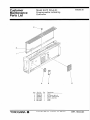
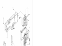
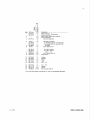
Customer Maintenance Parts bist.......,..
● ● O ● ■ 7−2.Disassembling alld Reassembling Prooedufes
●
■
■ ● ● ●
7−1. Troublesllootl㎞g Flo wcha士ts....
●
・ TROUBLESHOOTING...........
● ● O ・ 7.
●
● Actions to be Taken When FAIL anψ∼LM Lam血s Light Up.
● ● ● ● ● ■ ● ● o ●
●
●
●
・ 5−7.
6−2.Test, Calibration, alld Adjustment .
■ Sett血g an d Display of A(巧ustable Set−point Filter Functio11.
Automatic Control.......ざ.............・.........
6−1.Test Equipment........,........
噸 5−5.
5−6.
MAINTENANCE........................ .... 6...
● Settj㎞g and Display of Self−Tuning Functio11.....
● Start_Up and Operation.。....。.....・.・.・..
5−4.
・ ・ ● ● ●
5−3.
6−3.Parts Replaoemellt.......... . ...
● 噂 ・ Preparations for Operation .........・.......
圏 O ・ ■ . O ■
Names and Functions of Components.........
. ● ・ ● ● ● ・
● ● ● ● ● ● ●
. . . O o− ● ●
願 . ・ ● ● ● ●
5−1.
5−2.
5−8.
6.
● OPBRATION.....................
■ 5
● ● O 邑 O
4−2.Principles of Computation and Control
■ ○ ● O ● O
PRINCIPLES OF OPERATION........
タ・1・Ci・cuit D・寧・⑪tl・n・…・∴……
O O ● ● ・
●
●
・ . 4.
■
● ■ ● ● 夏NSTALLAT亘ON..................
3−1.Wiring .......,.............
. ・.﹂
2−4. Accessories ...............・...
3.
。 ● ● ● ・ .
2−3. Optional Specifications ..........
. 2−2. Model and Suffix Codes..........
● O ■ ● O
1−2. References ..................
◎ ・ ● ’1−1.Confirm Model and Suffix Codes.....
層 ● ● 0 .
INπIAL 1NSP£CT10N.。............
● ●
P㎏θ
● ● ● O O
1
7f∫’ε
1
1111333111111180145691
レレレ㍗㍗㍗㍗㍗鋲卸↑一一畠餌畠4↓444↓↑↑↑↑㍗㍗㍗
3ε0だ0η
. .CMPL IB4C2−04E
● ● ● ● ● ■ ● ● o ■
POWER SUPPLY TE㎜INALS fbr PANEレMOUNTED夏NSTRUMENTS(br/HTB)
IM lB4F1−11E
lMlB4C2−04E
⑥Copyright Nov.1989{KY).5th Edition:Mar 2007(KP)
’
ノ
、
1−1
1.INITIAL INSPECTION.
This instrument was thoroughly fac亡ory−tested be−
1−2.Referellces.
fbre shipment. When the instrument is received, how−
ever, check visually負)r any external damage that may
This instructioll manual provides information
have occurred during transit. Insure that it is complete
about the handlillg of the SLPC Programmable
with all standard accessories.
Indicat血g ControUer, its operational procedure, and
Read this section carefully before operating the
s㎞plifie d maintellance workflows.
SLPC Programmable Indicating Controller. For items
To run the SL,PC to fully support your applications,
not covered in this section refer to the apPropriate
certain preparatory steps are required, including the
sections in the manual. ’
processes of generatlng a program on instrumentatioh
now sheet fbrms and loading the resultant program in
1−1.Confirm Model and Suffix Codes.
read−only memory(ROM).
Information on these operations is ava丑able in
The model and su伍x codes are on the name−plate
specific manuals.
on the side panel of the instrument. Check them
Step 1:Information and materiahelated to program
against the model and su伍x codes given in Section 2−
generation.
2to make sure that the instrument meets your specih−
①YS80 Programmable lndicati皿g Controller Func−
cat10ns.
tions and Applications−Technical Information
If you have any questions about this instrument,
TIIB4C2−02E
please colltact either your nearest Yokogawa Sales&
②SLPC Worksheet
Service Offic60r Yokogawa耳1ectric Corporation,
③SLPC Data Sheet
④SLPC Data Sheet
Tbkyo, Japan。
WSIB4C2−11
WS IB4C2−12E
WSIB4C2−14
WSlB4C2−15
⑤S:LPC Program Sheet
⑤SLPC Colltrol Module Sea1
邑/
…∫E嘱8・ロ甑卿謂徽二こ7隔離蹴噂
5【」口7回r,▼7ゆ属回口
WORKSHE訂 ロ
@ ロ
’・
・‘・5E・・58。日、__瓢蹴ニニ識盟撃
cA漏H田’口…漏瓢『綴聯「
@ 口肌蝿卿_曲r器綴謬裂灘 閲」5ゴ07¶,7侮ロロ属,胃レ・レ
つ燭卿_..伽酬r馴醐
ド/
@ 口騙瀦媒瓢ほ漁瓢縞㍊離
験5飼o
@◎ 1
ィ勘
ェダ.層 、・・1・w・,、.i}・国;:::≡lll・…’t:・唱’隔,1’・唱・,「1.w
@ i・’・・柵’・i・’「
門馬・コー,
@ 、・1’1艸 ・・桝;”.i’,’ …5・・: ・・!’‘,i・・’監 門、’・一、li… ll雷’・1…,!、.、,・≡、1・,樽.1・,_…
Ol
’巴2
口署
3巴1
ε4
α3
o■
‘5
c‘5
【6
c「6
艦7
c臨7
‘6
㍑
1,鳥隔
Oo7
Oo帆
Oo91
0013
Oo●
Dg隅
‘,
c頃
Ol9
◎015
【10
O邑0
匡18.
o■1
‘12
o■12
x,砂隔
−一.一
・.し‘2一,
恥胃聞.馳隔
囲
Oolo
浴恆、の剛5■1嚇,c●禽.
7A5胸、
SI・P●,・吋・即 伽m㎝巴 3艦叩 F・開・㎝ c・…關竃
■ ● ● 1 − P
口臨16
7蝋
’
恥吊闘的
qZ,
…鯛
P 6
旧
@ i
Q 7
「一.,9,
.
■髄9
ィ■
Ol胴
【馳・
Ol4
【監5
口95
’雍 二rL・=・・」:;;;≡F_r=5i:・掌ii:
@ }. ・‘ ‘
肥 ● 闘●q曜L●
@ Fr.『 ・’子乙唱1’・”」i’レ ”rr=.:し.
@ 1、1・・
@ 1’苧=’‘・葦;i;・ 『川
.r
V 2
@ 「麗
、 3
一
X 4
C一一,.
Di・3F・1 聖・・雷 駄「雷・軍r・:『
@ 国
一
O 5
5 −
7蝋1嗣.
㎞㈲Pり●5催’滑6
口=■
欝ε欝蹴∼澱器轟550乙‘剛12」鳥5MOO【ロ晶AIlC…画動0臨MOO駄5
冒幽 口竃燭9P, u●㎞
普怫q
S 9
T 0
ψ
@ 、T・=
「“■
”署唱
k●」醒
欝
簡零隅
t89凹●
津
一
T 璽 一
噂55¢5酬贈〇一酬
c門刊
1=9幽6岡囲9駒開朔
25●【陶
‘椰2
3;阿〇一翻の5●嘱」
‘階,
o;騒嗣5岬
●3胴廟嚇9脚鱒
誧ユ「即
P=駆6剛
醐9幽1噂階「四向d
@1“6kM噸朗1一
1
嘲
o=c継o齢輌
P’脚0薗…
P=1脚釦」脚●冒r‘
Q.』【曜寧【榊
鵬6剛3』醐r悶
閧P’‘餌置5●■,■剛
怐@ 3
7π
4
X 4 一・噂,一
Z 5
一一,・幽幽,
6「.
@●
@2
@7 7●●r.
@3一・層
■■胃一
@5‘ 1
@8
@ 9
響■7,一”■■r,
属腿
“
嘱隠
属o,
属噂
㎜
@ :1.
13・1㌧1=;=1「1.
@ =『嘱r ,3・r,=乱・}:・=≡=・
タ3圏1・
@ 「 .:81≡3
@ ・=≡=噂’==
@ ・・’嵩・・’ ,}粗;’
醐画
薦ρ
:聖・=・’噺㌧』13匹., 、…i・=,
@r =
o■
「冨2
一一●●
T 1昌凱噺剛
M“㎝伽買鳩墨曜6
■.勘噛隔囁9
ハ‘陶髄5騨剛一
酬
6‘・6巳5
“卜HII■■。1岡 u・‘19醐・凹鎚
4}■民●9
艮研,嶋,
賜,・属‘1
‘脚唱,ら属P5。関5
P20・P”
器惚4C2・11
? 8昭電・」の■9‘.●r脚・■隣 御圏脚“わ●●のo,帥
●●,F民乳‘翼嘱po鵠9 ●【切凸‘飼
P.「加MF 「醐lr附‘駒
q3餌o鱒‘閥 麗P 闘o幽巳【轟
。・”一
馳
3≡二i乙、’
哩輔 岡
険3●● 眠‘四 閃嗣亀”
‘阿 覧一・「F一冒
宴ム馴瞳5白の朝
Q呂A噂5幽閏陶
囲
一
lWork sheet
WS 16弓C塾54 1 ■川桝朋鱒噸’噌■
@ 爵咽ゆ岬■,畠l
‘嶋廟1蹟
謇Rp c脚蝿願
㎜0」巳眞
岡
儒16
㎝
奄堰@rlr:=_
P ■
=@5”鱒
剛5
旧o
Elr旧・i”
@ .・i・::8iir
≡ ・
梶,■
翼◎9
匡
C・了i’iii’櫛.雷・:
‘
@4 .
.一7一璽一
@ l・
@ ・8i:’『 @ 1層
・’‘・ …、1,・
439のo一
軌…継酬
P1■ゆ噸幽隠
匿oら
,一
@ 層唱匹.F開
E匹∼F一・「
E;=,;=7i
o;翼凹●●■崩噌
3
@..:、・
‘層≡ 、唱l
@ ・1’.F’r二
i川’・・ W”rr,・”.、「’
@ ,1
堰E−≡15…1・T
撃戟=D㌧…・r国’ @ :1:
E’ @・[’‘… 1・’1’・・:.・
@,・1・.
@ .P.5..
@ 1旨,・、・・.層…’=:2ir門1層㌧門
@ 1「
普e層
贈
P=1繭舶闘
c㎝■r酬c㎝凶胤咽
2
r監.「
睡竃賜
閣轟㈲
Pε」響暢の0●
ε禰
.・一一...■曾,.一雪
・1「1層
,1・・1.1,‘.
@ 、・「星r
属
u一甲一
c9門鱒159縣・陵・lioo
A1,
V 2
F≡≡・3”
@ ’糧・:
曇=r・・.「臨「、,
?. }
評1 1
●●圓伽圏
65◎G騨りのc騨嘲‘
`ulo㈹晦翻
一
P層■ 5;、;:
.珊雷i
属
ロ冒需●
,響
’1’τ・’,8.・
1・;
11:1:
鳳
R 8
’=・宅・、聖’・1
u
.i・’
D・
制
一■.一「
層,
Q 7
F7
ll ・
rF 層iil;=弔
@ ㌧軍㍑=・_払層 1・i・
伽1剛Mo6囚●
一
@ ≡’・}・旨㌧ ・1=1・層 ;:‘1・「
@ し.・,r,’ ・}F il_;・11…・… 1・ ・i・… ll、.・
幽 , , ● 曹
”o
@ 3F 門 ’1’=‘・1・,、,、_雷.匹・:さ
8
夢一,・一■胃
U 1
@ .=,}悼1∴・1:
E
‘▼9
曾■
● ,
T 0 ,
曜13
翼膨’怨
R 8
S 9
卿剛一
c1’1!・” ・’出…幽・1・…1…■1 ≡1・・1_・’・
呂繍{畿綴幽1
口n
’‘匹
‘節鴨 暉帽 し●●● 冒,闘
o脅.飼●
P・Ao●乳o剛
撃・「・・ ‘層・・:雷11,、・1・:i席,1
@ ’,・・1・、’1・1・,..,9 ・ド撒. :1;.
…ま=1…i;壌i≡≡}1
牽= i1
5Pしr7●7,,7凸罰露“
@w;’碍・・” ≡li;=ii・iir lir脳
E1・:騙 ・・【欄・1、’1・3.1・・
.F
一
PROGR貞闇SHE訂」開L闘動r・欄…恥岬闘”MO 5L閏cρ「昂異■匹力■属” L8駄鵬P・剛蝋制恥¢・隔1・・81酬P胃伽■M,
凸り陶7n ・
цヘ卸“●紬
黶=F・・ 、。「.1!・’・w、’;1・一・脳・1・;・‘1円,・‘・’聖
齢騨陶
戟E1轟,
1繍1調綴L,1
圏一一楠繭
揃or【鳩1
915・2・,
7《6簡 ,
潤恪?圓●
監L 【齢 紀 曜 闘脚晒5
㎞蜘
馳
TG」幅79,,▼7轟翻冨凋,騨,●診 ■齢d隔
国F FI 8 τ
,‘唱髄●
o師輿● 駅‘ 一● 閥扁
一 既/
梶w5藍“IE58・ユ鵬卵_編鵜二認聯 劇噌嶋・」
le繍陶
‘圏5,r囎謄騨咽画殉o闘Ψ圏lb●51●鵬●
飼陀鰯●幅
o●・
■配陶 翼c 巳●鱒 駒扇
?夢ψ5轟・c繭・
9剛鴎●
‘輔網脚7
^
5L梶’偏昇幽幽肉鱒醒髄“螺動●卿馴騨閲国・6。明.●r隔rl陶。叫■叫
Data sheet.
1−2
Step 2:Instructioll manuals related to loading pro.
Step 3:Install the ROM in the SL,PC and proceed
grams hl ROM.
with operations.
①SPRG Programmer lnstruction Manua1(NQte)
This instruction mallual is concerned with the
IM lB4W1−02E
operations for step 3.
②YS80 Programmable Indicating Controller Func−
tiolls and Applications TI l B4C2−02E
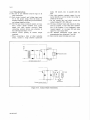
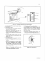
Nameplate
N
SPRG Programmer
Figure 1−2−2. User ROM and SPRG Programmer.
Figure 1−2・3. SL,PC Programmable Indicating
Controller.
Note:When the SPRG(Style A)programmer is used
for programming, only the functions of the SLPC
(Style A) progra㎞mable indicating controller
[asu切ect of the functions of th6 SLPC(Style E)]
can be programmed.
■
L
1MIB4C2−04E
2−1
2.INTROI)UCTION.
The SLPC Programmable lndicating Colltroller is a
Cρn重ml Mo“e Switching:By C!AIM switches or a
microprocessor−based, user−programmable. instrument
μser−program;ned de∬nition.
which provides signal computation and control fUlnc−
ず
tions as we11 as sequence logic fU,nctions. 、
Manual IOutp耐 Opemtion:Tw(トspeed lever action.
Parameter Sett血1g and Data pisplay:Fro]出 tunh耳g
In addition to simple PID control, batch control
pane1(side pI翼1e1).
and sample−and−hold PI control, the SLPC’s control
Progr㎜mable F㎜ction Key(PF key):1key(which
hmctions indude variable−galn control and dead−time
can be used as status illput signa1).
compensation contro1;and a single SLPC can simulate.、
PF Lamp:llamp(which can be tumed onloff by
two controllers in a cascade control or autoselector
user program).
control configuration.
Anew intelligent selfLtuning model automatically
Control F㎜c髄ons
optiπ1iz6s PID parameters.
Co蹴trQI Modules: 1 ,
Auser−a(珈stable set−point filter, used to improve
Basic Control Module:Asillgle control modu.le.
the response to set−point changes, is also provided as a
Cascade Control Module:Two contτ01 modules con・
standard fbature.
nected hl cascade. One SLPC controUer can血mple・
There are about 46 d臨rent computational and(se−
quence)10gic hmctions;these can be freely combined
ment a cascade looP. An arithmetic computation
may be performed bet脚eenかrimary and secondary.
to create user−defined fUnctionsl And, by using
controllers.
subprograms, even‘‘large”or oomplex application.
Signal Selector Control琿odule:Two colltrol modules
programs can be easily realized.
connected.血para皿el. One S■PC colltroller can
The SLPC controller is as easy to program as an
implement an autoselector Oontrol looP.
electronic calculator, ll is programmed by conllecting it
Functions in Common in the Modules above:Output
to an SPRG programmer.
tracking, output limiter.
Control Elements:
2−1.Standard Sp㏄i血。就ions
AControl Module Comprises One of Three C6ntro1.
Elemellts:Basic PID control element, Sample−and−
Input/Output Signals
Hold PI control elemellt or PID control ele丘nent’
Analog h叩ut Signa阻:1to.5VDC,5poillts.
with batch switch. These control elements, des−
Analog Output. Signal:Ito 5 V DC,2points
cribed above, may contain the following common
4to 20mA Dc, l point.
functions:Process variable.hig11!10w limit alarms,
Status蚕nput Signai:Contact or voltage Ievel
velocity limit alarm, deviation alarm, set point
ヒ
Status Output Signa匪:Trallsistor colltact
transmission, input compensation signal addition,
6points(user−defined.as output or input)
110nlinear control, vaゴable ga㎞l feedfolward・signal
ノ
Fail Output Signal:Transistor colltact, l point
addition.
This contact output is open in the fail state(also
Adjustable Filter for Set−Poin重Changes=
open when power fhils).
Response to seや。血t changes can be a{動usted.
Two a4justmellt parameteτs(for eadl set po血t).
Indication/Setting/Operation Fullctions
Self−tuning Func重ion.(in SLPC一丁81)F6atures:
Process Variable alld Set−Point Indicators:
Self㌦tuning selector(ON!OFF)switch(can be qper−
Dual pointer movhlg coil meter or lluorescellt bar
ated manually or by use士program),
graph indicator, plus a fbur−digit numeric display.
L㎞its can be set for tuning of PID parameters.
Output 1夏mdicator:Movihg coil indicator.
Control and Computatiollal Period9:.0.20r O.l
Setting Methods:’
seconds.
Mallual Setting:Setti置1g speed 40.sec./full scale.
Remote Setti119:βy input signal or computatio11・
IMIB4C2−04E
2−2
Computational Functions
Mounthlg: 〆
Flush panel mounting. Instruments ar6 ill hous−
Max. no. of
Functions
Function name
times function
may b色used
oln program
Addition, Subtraction,
Multiplication, Division,
GeneraI
functions
Magnitude{absolute value},
Square root with’10w−signal
一
一
一
一
cutoff”.,
High selector, Low selector,
High limiter, Low lim、iter
10−segment tranSfer function
一
2
The instrulh6nt may be tilted in the front up to 75。
血om vertical(rear of instrument lower than ffont).
(Zero indicator may need readjustment).
Wiring:
Signal Wirillg to/from the Field:ISO M4 size(4 mm)
Powemlld Gromld Wirii19:
100Vversion:JIS C 8303 two−p㎞plug with grounding
(IEC A5−15, UL498).
げ
220Vversio11:CEE 7 VII(CENELEC standard)plug。
(two functions)
Power C劉ble Length:30cm(11.8h1).
Transfer function with user一
definable number of segments
2
Housing Dimensions=182.5’(H).× 87(W)× 480
High limit alarms
4
4
(D:depth behilld palle1)(mm)(7.2 × 3.4 ×
with unit
Low limit alarms
addresses
First−order Iag
署
side.
● screws on termillal block.
一
{user−definable break points}
Functions
1ngs, and may be moullted individuaUy or side−by−
First−order lead
8
2
Dead−time, velocity computa一
tions and moving average
Velocity Iimiter
3tota1
6
18.9in).
Weight: ’
Controller Unit:3.4kg(751b).
Housi119:2kg(4.41b) (excludillg nloullting kit),
Timers
4
No㎜al Operating℃onditions
Program set unit
1
Ambient Temperaturel O to 50。C(32 to l22。F).
Detection of status change
8
Pulse input counter .
4
Pulse rate output
2
AND, OR, XOR, NOT,
equal}
functions
Branching, Conditional
(11011−colldensi119).
Power Supp艮y:Two versiolls, for」も100 V”(stalldard)
一
CMP(test if greater thah or
LogicaI
Ambiellt Humidity:5to 90% Relative Hurhidity
or‘‘220 V,,(optional/A2ER). Both versions may
use AC or DC, without change to the instrument:
一
100V
220V
Subroutine calls
一
DC(polaritγreversible》
Signal switching
20to 130V
120to 340V
一
♪
`C(47 to 63Hz)
80to 138V
138to 264V
Version
branching.
Note:Where limits are indicated by a dash’L”above, this
means that there is no preset limit.
CommuniCation Functions .・
The SLPC can communicate(via. an LCS card in
YEWPACK,μXL/CENTUM)Ψith a central
YEWPACK,μXL/CENTUM CRT−display operator
station. The SLPC can also communicate with an
SCMS Programmable Computing Station,(The
SLPC can be connected to both an LCS card and
SCMS). The maximum Iength of cable(SCCD
cable)to LCS card or SCMS computing station is
100m(328 ft).
㌔
ノ
IMIB4C2−04E
㌧
r
﹁
2一一3
2−2.Model and Su伍x Codes.
2−3.Optional Spec迂ications.
匹
Su{fix
Model
Style
モ盾р??
Option
、 Description
1NP奪:Controller supplied unprogrammed (with
blallk早P RO1》1). The user can write his program to
モ盾р??
EPROM usi㎡g a SPRG Program血er.
SしPC
・ ● ● . ■ ■ , ●
・ . . ● ●
. ● ● , ■ o
Programmable hdicat一
ing Controller
一1
lndicator
│2
Functions
書 ● ■ ■ ■
9 ● ● 0 9
・ o o 9 ・ o
E ・ ■ ■ o
E ・ , o ●
怐@ ・ o o o ●
o ● . . ●
… P ・ ・
5
o ・ ●
● o , ● ●
・ ■ …
Style code
一
一
9
options
一 一 _
1MTS:Controller supplied with kit for separate.
mount1119.
1scF。G口M:Mounting kit bezel color change from
adjustable filter and
standard color(black). Choose color from set of
self−tuning’function
optiollal colors (see GS ’22DIF1−E). Specify
, , ・ ■ ■ ■
Always 1
color code in space口.
Style E
1NHS:No housing, instmment only. See GS. l B4F1−
・ g o ・ o ■
!NPR
Unprogrammed
Eto order housing separately.
^UPR
vith user program
賛E.。
Options
1A2ER:For‘‘220 v version”power supply.
Enhanced model, with
● ● ● ● ● ●
1
Common
Enhanced model, with
≠р撃浮唐狽≠bP6 filter
8...
一 一 一 一 一 一
Moving coil
eluorescent bar graph鱒2
1UPR:Controller supplied with usgr program pre−
pared in YOKOGAWA M&C configuration.
一 一 一
ノNPF:Letters engraΨed on front panel血ameplate.
一 一 『 一 一 一 一 _
!A2EiR
220V power supply骨1
1MTS
With mounting kit
2−4.Accessories.
!SCF
Bezel color change
Fuse(1 A):1piece. Part No. S9510VK 』
│G口M
!NHS
!NPE
Without housing
Nameplate engraving
ROM:1module.(When NPR’is selected, the cont−
roller is supplied with blank ROM.)
Part No. A 1123LQ\
骨1Specify IA2/NHS to order without housing.
Note:The血se(S9510VIO is the dedicated血lse, Do not
管2The order acceptance of fluorescent bar graph is discontinued.
use it長)r other products.
L
iMIB4C2・04E
3−1
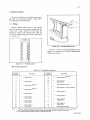
3.INSTAL,LATION.
For general infbrmatlon on installation an¢mount−
、
ing, refbr to the Instruction Manual,‘‘Panel Instru−
ment Mounting,,(IM IB4F1−01E).
、
o
、
3−1.Wiring.
且
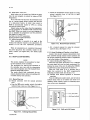
d∠ヨ
Connect external signal wires to the terminal
board on the rear of the con亡roller housing with M4
(4mm)size screws. Remove the cover from the
housing fbr access to the terminal board. Place the
cover in its original position af㌃er wiring.(See Figures
3−1−1and 3−1−2.)
●
①③⑤⑦⑨⑪⑬⑮⑰⑲⑳.●②④⑥⑧⑩⑫⑭⑯⑱⑳④⑧◎⑪㊦⑪①⑭①⑰⑪
Figure 3・1・2. Terminal Board Cover.
.Table 3−1−1 shows the terminal desigllatiolls and
sigllals to be connected to the SL,PC Programlhable
Indicating Controller.
Figure 3・1・1. Terminal Layout.
■Terminal Connections
Table 3−1・1. Terminal Connections.
Terminal
cesignation
1
1 5
十
> Analog input 1
一
十 > Analog input 2一
34
2
Description
Terminal
cesignation
17
十 (Note 2)
18
一
19
Q0
+ {Note 1》 > Analog input 3
21
6
一
A
7
+ (Nbte 1}
B
8
『
11
D
> Analog input 5
一
士.>1吊望・課}1
P2
P3
P4
P5
P6
C
S〉瀧鵬2
{>S…uss・g・・13 一_ (IN3,0UT4) .
F
HJKLMN
10
十
9
>Analog input 4
>Communications
士〉瀧魏}4
一 Fail{negative terminal}
十
@ し
Description
1
十 > Analbg output 2
一
十
〉.Analog output 3一士>1継囎)6 ,+>S…us signal 5_ {IN5、 OUT2}十 Fail{positive terminal}
Note:1. A lumper is attached between terminals 6 and 8..Use it to short terminals A and B when current output is not
used. Terminals 6 and 8 have no effect on instrument operation and can be shorted or Ieft open.
2.Use shielded twisted。pair SCCD cables for communication騨nes, . ..
1MIB4C2−04E
∼
3−2,
3−1−1.Wiring Instructions. .、
diode, CR’circuit, etc.)in parallel with the
(1)Be sure to use solderless crimp−o血lugs on all
load.
cable connections.
oNote that transistor contacts cannot be con−
(2)Each status(contact)and voltage tnput must
nected dtrectly to an AC circuit. Use a relay to
be of the proper rating. Note the limits on
switch an AC circuit.
leadwire resistance, voltage drop across leadwires,
oDo not connect any load which exceeds the
and voltage(high/low)levels.
contact rating(30VDC,200 mA).
(3) The fail and. status(contact)outputs are tran−
(4) The status(contact)inputs and outputs are desig一
sistor contact signals (isolated from power
亀nated by program, so wire them after confirma−
supply and other internal circuitry). When
tion of the program. If not designat6d, status
connecting external devices, pay attention to
(contact)signals l to 3 are input(DI)and status
the.following(see Figure 3−1−3):
・signal 4.to 6 are output(DO).
0 0bserve correct polarity of contact output
(5’)Use shielded twisted−pair SCCD cables for
termihals.
communication lines(terminals 17 and 18),
OWhen conllecting a relay oゴother inductive
(6)Short current output terminals not in use.
device, connegt a surge absorber (protective
、
Vbc
Positive
十
O
でσO﹂
1
Protective diode
o
Negative
Contact output circuit
Relav
ノ
o
Contact output circuit
AC Ioad
℃価O﹂
一 一
﹁一−−一﹂
己
1
一一1ーーー1−1﹂
o
∼
AC source
Figure 3−1−3. Contact Output Connections.
lMIB4C2−04E
‘
、
4−1
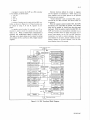
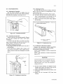
4.PRINCIPLES OF OPERATION.
4−1.Circuit Descriptions.
See the SLPC circuit block diagram on page 4−4.
The watch−dqg timer(WDT)connected to the
CPU superviseg the CPU operation−it cau呂es the
FAIL lamp to light up and outputs a fail contact signal
if the CPU fails. If the CPU fails, the manipulated out−
4−1−1.Analog Illput Circuit.
put current signal(Y 1)is automatically isolated from
Avoltage input signal enters the input circuit
the digital circuit, and can be varied manually. The
consisting of RIN,・R1;and C1. RIN uses a high value of
measurement indicator then automatically indicates
resistance(1MΩ), so it normally does not affect
the value of input signal No.1(X1).
circuit operation. However, if the input c廿cuit opens、
(input is disconnected),it provides a DC path between
4・1−5.A血alog Output Circuit.
(十)an4(一)input terminals to prevent the buildup
The ahalog output signals, after digital−to−analog
of statlc charge on the(十)input Iine. O V DC input
conversion, are fed via the output demultiplexer and
(e.9.,input is open) is・equiValent to −25(X)qf the
buffer amphfier to tlle current’and voltage output
range.
RI and CI form an input filter with a time constant
The analog output signal negative line is common,
of apProximately O.1 sec.
and is connected dh’ectly to the analog input signal
All analog−input negative leads are connected to a
common negative line.
circuits.
ρommon line inside the SLPC.
4鱒1−6.Digital Output Circuit.
4−1−2.Analogイ。・Digital Converter Circuit.
The digital output signals are transformer−isolated
Analog input signals enterhlg the input circuit are
and output to the field as open』collector cohtact
sequentially selected by the input multiplexer. The
comparator compa}es an input signal with the o廿tput
signals.(When the citcuit is designated for output.
by a program).
of the digital−to analog converter ch℃uit, and the CPU
adjusts the converter output so that the two signals
4−2.Principles.of Computation and Control.
ar6 equal−basically, a successive−apProximation type
of analog−to−digital converter. The corresponding
digital value is. 唐狽盾窒?d in data memory(RAM).
4・2・1.Principles of Computat,on.
The SLPC performs three basic operations. It reads
the mput signal, computes, and outputs the com−
4−1・3.Digital Input Circuit.
puted result. The example in Figure 4−2−1 shows how
to program the addition of two input signals. Figuτe
transformer in the input circuit. Input status is read
’4。2−2shovレs how the stack registers S−change during
、
Each digita1(status)input signal is isolated by a
vla an lnput port and transmitted via the data bus to
the program. All computations are performed in the
RAM.(When the circuit is designated for input by
common stack registers S. Connection of signals to
aprogram).
At the same time as the digital input are read, the
switch status(SET,.CIAIM, MV, PF, TUNI:NG,
the registers−that is, input to the S registers− is
performed by means of the LOAD(LD)instruction.
The S registers, Sl thru S5, comprise a ‘‘stack,”
ACTION)on the instrument f『ont and side panels is
and data in S is pushed down(串1 to S2, S2 to S3,
also read and stored in RAM.
and so on)each time llew data is input by the LD
lllstructlon.
44・4.Digital Computing qircuit.
When all the input data is read, the microprocessor
(CPU)carries out data processing according to the
Arithmetic operations can be performed on
data thus血put byμsing FUNCTION instructions.
There are approximately 46 di脆rent computational
com加tation/control program stored in User ROM.
and control FUNCTION instru6tions. These instruc−
The results of computation and control are output
tions are entered using their associated Symbols, such
via the digita1−to−analog converter circuit or output
as十,÷,and HSL. The result of a computation per.
画ts.
負)rmed on the necessary number of data stored in S
1f‘asupervisory system is c6nnected, data com−
registers is poPPed up to top register S 1.
munications玲performed via a loop commullica−
The STORE(ST)instruction is used to retrieve the
tion caτd(LCS). The communications line is isolated
from the controller by a photocoupler.
result of computation and store it in an output
register(to be described later). Execution of the ST
instruction does not affect the contents of the S
registers.
4−2
﹁
’
X1
4−2・2.Input10utput Register Configumtion.
Figure 4−2−3 shows the configuration of the
X2
LD Xl
}Read・・X1’・・
SLPC’s input/output registers. Analo9,αigita1, and set
LDX2
十 .
STY1
parameter inputs are read into registers XN, DIN,
and PN before」execution of the us6r program begins.
}Additi。・
The user program reads required input signals and
}0・tp・t
parameters from the respective input registers into
computed result
Y1
the arithmetic register using the LD instructions, and
stores the computed results in output registers YN and
Figure 4・2・1. Two−Input Adder and Program.
DOn using ST instructions. Finally, the controller out−
puts the contents of output registers YN and DOn as
analog or digital values. This・cycle repeats itself 6very
LD.X1
LDX2
X1
X2
STY1
十
O.2sorO.1s. 、
Y1
4・2・3.Principles of Operation of Control Modules.
The SLPC Indicating Controller illcorporates three
−n乙Q︶4[O
SSS︻b︻b
X1
A
control modules:
X2
X1
X1+X2
A
B
C
B
C
A
B
C
D
・C
X1+X2
O
A
Basic control module(BSC), which qonsists of one
colltroller contained in a single module.
B
C
C
O Cascade control module(CSC), which consists of
,two controllers combined in series.
O Signal selector control module (SSC), which
consists of two controllers combined in parallel,
Lost
selects one of three signals:either one of two
controller outputs or an input signal.
Figure 4−2−2.
Behavior of Arithmetic Registers
Associated with the Sample Program.
ト
1to 5 V
A/D
lnput regiSters
XN
DIN
▼
▲
PN
Analo9 ・・p…Dig…li・p… 9呂麗纏gnal
@ ト
LOAD X1
FUNC BSC
STORE Y1
Anaio9
Output registers
ou㌻puts Digital outputs
YN
DOn
YN i l l
.D/A
4to 20mA
、
lto5V
Figure 4・2・3. Inputlo耐put Register Configuration.
lMIB4C2−04E
㊤
iIl
Eo﹂Oo﹂α﹂Φ切⊃co旧ω﹂Φきoo言α言O
Repeated every
O.2s(orO.1s).
=O旧ω﹂①﹀⊂OO↑⊃α⊆一
/
1 幽
4−3
AI program to operate the SLPC as a PlD contro11er
Optional fUnctions de血ned by certain A registers
is very simple, as shown below:
and FL registers.are initialized toもしOFF’status, and
1.LDX1
these register『may be simply ignored if the gptional
2.BSC
fUllctiolls are not required・
3,STYl
4.END
も℃011trol elements’うsuch as standard PD, sample−
an.d−hold PI, and PID colltroller with batch switch can
Avariety of optlolls call be used with the BSC con−
be selected.
troiler, as shown ill Figure 4−2−4. These functions can
With the cascade control module CSC, the SLPC
be utilized by using A, B. alld FL.registers in pro−
functions as two cOntrollers血cas6ade. The cascade
grams・
lQop can be opened or closed from the’side panel
111cascade colltrol rllode, fbr example, all ST i11−
keyboard. With the selector control module SSC, the
slruction ls used 圭。 store the cascade set poillt lllpUt
SLPC call fullctioll as all autoselector controller or as a
value in A1. When a feedforward compensation is
required, the feedforward signal is stored in A4.
several illput sigllals. As the CSC alld SSC functiolls
The hlgh or low alarm status can be output by storing
hlcorporate t∼を。 built−ill control.elements、 the front
the¢ontents of FLI and FL2 in DOn(digital output)
pallel displays the set poillt, process variable and mani−
traρking colltroller which call select and output one of
pulated variab】e of the nrst elemerlt, alld the side
モ
reglsters.
pallel displays those of the second. .
﹂
Process Variable{PV, lnput
S1
A1
A!M
Procogs V8riabb
@ Pointθr
Volocity Alarm VLり
b、
Sgt・Point lndex
A12
Setpoi「1t.Output
A2
hputComponsation
一一一一一
一
@ DL1
十
撃h一
一
.
P冒Standard
@ PID
Nonlin8ar Gap GW1
Q=Samplo−and・
@ Hold Pl
Nonlin8ar Gaih GG1
R=Batch PID
PBI Propotional
Sampling Pgriod ST1
@ Band
Control Time Width
Tll lntggral Tim6
@ SW1
‘
Batch D6viation
rotpoint BD1
十
A9
Batch Bias Vaiuo BB1 ,
Output
bompons8tlon
Output Tracking
S唱「CS竃飢u6・
bNTl
B18 SVF parameterα
B19 SVFparameterβ
A4
FL3
BO8
Doviation Sotpoint
十
A3
@ Timo
Deviation Al8rm DL1
Volocity Timo Duration
@ 、
Doviation Al8rm
TDI Derivativo
FL10
V●Ooclty S6tpolnt VL1.
@ 、
、
A16
C!ATran5f6r
LowしimitSotpoint
@ PL1
Batch Lockup Width
@ 8L1
十
Z
一一一一一一一
Output Limiter
M“
C/A
FL18
eし30
eL31
Tracking
FL9
B11
OutputLow Limit
B12
A!MTransfor
FL11
@S6poi tML1
、 、_ _一
A14
S1
@ ,
@ 5
Manual
npor8tion
鼠 、
Manipulated.. Variablo
D 1
BO4
BO5
B13
B14
B15
B16
B17
Output High Limit
Sotpoint MH1
,
FL2
FL4
VT1
@ PH1
Cascado Sottlng
FL1
BO6
BO7
BO9
B10
High Limit Sotpoint
@Modg 2譜1)
BO1
Low Umit Alarm PL1
、
〔Appliod whon
BO2
BO3
High Limit Al8rm PHl
rL
騨
A15
﹁
▼
÷
*
’ ’ ﹂
三ξ
BSC
InputAlarm
ム
@ 1
I
lanipulatod Variablo
Figure 4−2−4. BSC Functional Block Diagram.
lMIB4C2−04E
一ロロ轟OM−O轟m
Q+月
黷P20
0 13十﹃140
919』
黷Q0◎
撃L〒Mo
華J−KQ
RlN Cl
R1
X4 RlN
X5 R雛N
10σ
go+
8σ『
C1
Rl
C1
R1
キ
7Q
6σ
十
十
Comparaセor
lnput
multiplexey
CPu
Manual oρeratlo雨ever
蝿甲回門
Output port
SV
D/A
RAM
Timer
十
ROM
System
Data bus
WDT
1.
LA、{P)
ドAlI5 \
FAIL
\’
vcc
ユ
ゴ
L NGND
O Q
SWR
muitiplexξ
Connector
7v
古
㍗
ル
programmer
for SPRG
十
・←
十
v+
Communications port
88置8●8「8置8‘醒9
●■■●■6■8■●●■■
User
ROM
Output
工
三三ロロ
ロロロロ
ロロロロ
ロロロロ
◎B
(4∼20mA)
Y1
十
h「‘hI躍 ΩA
MV
indicator
QD
(1∼5V)
Y2
OC
十
wo
eA
†Q
O18
Communication
+0 17
ラ
V
5
3、
FY口H
刃諭
X3
50
40一
x2 R:N C1
30+
R1
20−
十
C A M
LAMP
PV
PF
lrlput port
馬
ド州1』
、
/
■o。電6Ω器昌06δ集ヨ”。。§§
xl R‘N C1
DIOO6 DO
DIOO5
Qi
O盈
O−
DDD
DD
DD
D
R1
DI/DO
DI/DO
D1004
DlOO3
﹂Dom Q−
1()+
DOO1δK
0r
Dio6
DOO20
0r
Dl/DO
Dl!DO
DIOO2
DIOO1
’
DlO5
DOO3620
0r
DIO4
DOO4δ’6
0r
DllDO
D【!DO
D1
38θ
圃
DlO3 0
+15
DOO50
0r
DlO2
DOO60
oピ
DlOl
5ゲ
Indicator keyboard
轟−轟
〆
ノ
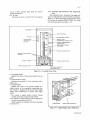
5−1
5.OPERATION.
/
5−1.:Names and Fllnctions of Components.
54−1.Controller with Movillg¢o皿Ind韮cator.
This Icontroler uses a movipg coil indicator for
indicating the process variable and setpoint. Figure
5−1−1shows the front view of this type of contrbller
(S:LPC−171*E);and Figure 5−1−2 shows the side view
of the controller. The names of panel controls, and
other components are also shown in these Figures.
ameplate
≡≡
008
FAIL
AILIamp(red)
゚一
≡≡
LM’LQ
≡曇≡
゚碁
PF lamp
一
≠高高≠b撃??
rET一 ▲ζ ▼
PF
O6
曇≡
゚≡一≡≡≡一≡⋮≡⋮≡≡曇⋮≡
on keye
磨p
(PF kev}
覧
≡=
O2
O
etpoint up/down keys
=
ー
ation mode ・s
?er switches O4
LARM bmp(yelbw}
etPoint index(bluel
□cl
ロAl
lllllll日
ロ副
lhll11
easurement poihter{red}
utput indicator
@ ‘m
嘲 (咽 レ )レ ?mory index
@ 1コ
anual operation lever
ontrol valve action labe1(open/close marks}
igure 5・1・1. Controller Front View.
MIB4C2−04E
5−2
Clamp
lntermediate stoPPer
Fuseholder
o
・、
Aノ 、、.
Moving coil indicator
Data−protect battery
@ 画1竃.雨一
’\
1
!
﹁
e
ミ\1
’!口
zero adjustment screw
N
『ミき
桑
−,∼.
@ 、 ミ』..
、 .,
顧r 秩f
Tuning panel
、
溜〃
・設
Fluorescent bar
graph indicator
㍉㌧
臥ミ
,
\瑛、
レ塾
1
黛
曳・ー
i・隔ミ ,㌔ 『 .●
﹁
Stopper
工
、、
@賢、 隔■、
−
軸,
o
N
まゆ
..、華・・−
ーーf−−﹁
矢
Set−point index.
●
、.
塑 副ζ鰯of
鰯
メi二陣 嘱1
撃宴 ・一 正風i§・一
o
・ Connector
_ 、嚇 .● 隔、﹃
﹁
/
f一
s \
1
Two−pole pIug with
grounding contact
Terminal board
Digital display select pushbutton(Other compone.nts are
identical with those of the moving coil indicator version.)
Figure 5・1・2. Controller Side View. ・
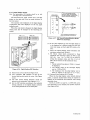
(1)FAIL lamp
Amode:Automatic contro1. The setpoint**is set by
Lights up when the controller fails.
using the SET pushbutton switches.
(2)ALM lamp
Mmode:Manual control. The manipulated output
Lights up to indicate the establishment of an alarm
signal can be increased or decreased by using the
cond亘tion, and flashes when data−protect battery
manual operation lever. The setpoint**can also be
voltage drops.
adjusted.
(3)Measurement pointer
(7) Output indicator
Indicates the value of the process variable*,
Indicates readings of the current output signal in
(4) Setpoillt index
the range 4 to 20 mA DC.
Indicates the value of the setpoint**.
(8)Manual operation lever
(5)Setpoint up/down keys
Used for adjusting the mani餌lated output signal
Used for adjusting the setpoint**. Operable while
of the controller in M mode.
in A(auto)or M.(manua1)mode.
Action:
Setting:
Moving the lever to the left decreases the signal
To increase setpoint, press囚key ’
output, while moving it to the right tncreases the
To decrease setpoint, press団key
signal output.
(The setpoint remains unchanged when the two
Settillg rate:
keys are pressed a重the same time.)
<,レ 40sec./fun scale
Setting rate:40 sec./fuu scale.
<<,レレ 4sec./fun scale
Fine adjustment:Pressing the key momentarily
Fine adjustment:. .
(for apProx. 0.2sec.) changes the setpoi皿t by
Moving the lever from the neutral position to the left
O.1%.
< or rightレmomenta雫ily (fbr approx.0.2 sec.)
(6)c/A/Mmode transfer switches
changes signal output by O.1(%.
The desired operation mode can be selected by
pressing the appropriate pushbutton. The.pushbutton
*For cascade or signal selector control:Process
variable of the f元rst control element(CNTI).
**For cascadサor signal selector contro1:Setpoint of
the first control element(CNT1).
us血g the computational functions, or by com−
(9)Programmable function key(PF key)
munications data.
When this key is pressed fbr about O.2 seconds, it
5
lMIB4C2−04E
,
’
bu丑t−hl indicator lamp Iights up.
C血ode:Automatic cOntrol. The setpoillt**is set
﹂
5−3
acts as a status (contact) input signal (by user−pro−
5。1−2.Contro皿er with Fluoτescent Bar Grapb Indi・
grammed de員nition).
cator.
(10)PF lamp
This contrgller uses a fluorescent bar graph indi−
This lamp can be lit or turn『d off by user program.
cator for indicating the proces5 variable and setpoillt.
Figure 5−1−3 shows the names of front panel controls
of this type of contro皿eri(SLPC−270*E). For a side
view of the instrument, see Figure 5−1−2.
Nameplate
一一
Programmable
function key
一
(PFkey}
?lO2
1ロcl
ALARM lamp《yel16w)
Setpoint index
(indic自ted by a bright cursor}
Process variable!setpo憲nt
digital display
Measurement indicator
{bar graph》
一▲璽▼
レ__ 0
Operation mode transfer
一
1,594
0.5
switches
_FAILlamp(red)
﹄ALM ’
’ 一
PF lamp
. FAIL
●m
C一一一一一一,一ロー,一一一,一一
PF
.O
Set point up/down keVs
一
旧Al lロMl
llllll川1川lllllll
Output indicator
㌦
o
Manual operation lever
ぐ4 く レ レレ
@ Irl
Output memory index
O
.,.
Control valve action labe1
{open/closed marks}
Figure 5−1−3. Controller Fmnt View.
(1) Bar graph display
Displays the value of the process variable*as a bar
grゆh.
(2) Setpoint index cursor
Indicates the setpoint**of the controller with a
brtght cursor.
(3)Digital display
Displays the value of the process variable as a
4−digit number tn the appropriate engineering unit.
The setpoint・is displayed wh且e the side−panel digital
display select pushbutton is pressed.(See Figure
5−1・4.)
* For cascade or signal selector contro1:Process
variable of the first control element(CNTI).
**For cascade or signal selector control:Setpo血t of
’
theξirst control element(CNT1).
Other functions are identical with those described
Digital display
ill Section 5−1−1.
Display select pushbutton
Figure 5r1・4. Digital Display Select Pusllbutto血.
〆
IMIB4C2−04E
5−4
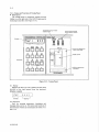
5。1−3.Names and Functions of Tuning Panel.
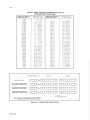
■ Panel layout
The tuning panel for parameter setting and data
display is on the right side of the SLPC Programmable
Indicating Controner.(See Figure 5−1−5.)
譜8留畿tlng hhiblt! D・・ec・ac・…ノ・eve・se action selector switch
lay
Display
PROGRAMMABLE CONTROI⊥ER
5〆’ 800 」
TUNING ACTION
dNA8巳_E DIR1 01R2
黶≠苧ルiiii]iLi! L︳︳︳︳︳︳︳﹂ 7
」TYPε一一」一〇ATA一一一一一一一」
MODEL PC
PNHI8「「 臼VSI RVS2
@ BA’「CH NON− PH
@【…N SAMPLE UNEAR T H
?□□□ L DL MV PH Vし 閉H 『⊇轟.D Pl. VT ML STC
@ ROM△
Cover for SPRG
獅?ctor and ROM
l l
?□□□ PV XN Dl SV YN DO CHECK DV SCALε MODE ALA只M
\
?vC盾≠窒
綷禔?□r−Nr 「一一一一一一TUM髄G一一一一「 金 ▼ § ▲.
qOM socket
rPRG programm
モ盾獅獅?cto?
「・・・・・・・・・・・… ◎「
P..。。◎。。。。。。.。。. 1
PROGRAMMER
Figure 5−1−5. Tuning P劉neL
ノ
(1)Display
Displays the data type code(TYPE)and data vahle
(DATA)of the data entered from the keyboard.
(Display example) ,
ρレ?
TYPE ・
午.ヨ∼,1
DATA
(2)Keyboard
Used for entering parameters, displaying and
changhlg data, and so o11. The names and functions of
the 1(eyboard switches are summarized in Tables 5−1−1
and 5−1−2.
lMIB4C2−04E
5−5
、
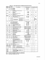
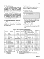
TaUe 5。1・1. Names and Functions of Tuning Panel Keyboard Switches.
Typ●
oTV陀,
吋“mbor
ni叩by
EN
EN
1⑩15
εregister5 ’
Cl
1to 15
CI rogi5ter5
0’1
DN
CO
ho 15
Dregi$ter5
一800.OtO800.0
1to 15
CO regi5ter9
8D
1
Deviation sot point
Oto 100.0
%
8B
1
8ia5 value
Oto100.0
%
1
Lockup width
Oto100.0
%
Oto9999
Oto9999
5ec
K●vbo8rd
S醜ting
%
x
一
x
011
一
■●
一
x
一
x
一
1 8L⋮
O
O
o ・
0.0
0.0
0ρ
Sampge●and・ho,d Pl control parameter5
ST
1.2
Sample time51periods}
SW
1.2
Control time$
L
Non・髄near control or 10・segm8nt function
1.2
H
1to 11
PN
’PN
10utput poimsl’
5et
Arbitrarily,sεgmonted
撃奄獅? segme“t function5
撃撃獅垂浮
Computional parameter5
E“gineering uoits disPIay
一
Compotiooal param飢or5
一800.Oto800曹0
%
OtO9999
20to 29
Program seuing l!imel
30to 39
Progr3m setting5こ口utput valuel
1to 16
Temporary storagle r8gister5
1.2
Adjustable set,point fiIter
parameter
1.2
Adβustable set.point filtel’
p訂ameter
Not used
Pr㏄ess variablo:hi白h limit alarm set
PL・●
PL
1.2
Process varlablo:Iow聴mit alarm set
Dし
DL
1.2
D的ia電ion alarm 50t point
OVL
1.2
Vdociw alarm:MV C島a”go in timo
Vτ
192
V810city a18m:Timg duration
P8
P.1.D
1
1.2
1.2
一
192 .
α
VT
%
一800.0電0800.0
一
0.000to 1.000
一
0.000to 1.000
一
O
o
一
一
εngineering units using SCALE
一
Engineering units using SCALE
一
Engineering uni脇usiog SCAしε
一
Engine町ing u“it5 using SCAしE
1電09999
一
5ec
Manipu量ated variab13
一6.3to 106.3
%
M8nipulated v8riable:High limit setpoim
一6.3to 106.3
%
M8nipubted variablo:Low limitsetpoint
一6.3to 106.3
STC modo designation
Ref6r to Section 54.
6.3to 9999
Proportior181 b3nd
一
%
「
STC
2⊃
Tl
1.2
1ntogral timo
1to 9999
sec
TD
1.2
Dgri》ati》e time
Oto 9999(Note 3}
5ec
lPto GM
SτCparamoter5
o
O
0
O
一25.Oto125.0
. 一
poim
poim
5ec
%
ML
%.
1to 8
1σ2
STC .
р?.琶lection points,
0.0
1,000
Linear
一25.Oto125.0
9電016
1.2
MV
MH
0.Oto100。0
0
o
o
0 .
3etting of
n.Oto100.0
{Output set points}
1to 11
PH
MV
MH
ML
一
‘1叩ut 由fl㏄tion points,
PH
L
0.000to 1.000
0
Rofer to Section 5■4.
PV
SV
PV
SV
DV
XN
YN
DV
XN
1to 5
An810g inpu竃register5
YN’
1to 6
Analog curren電output register Y 1
ε【ginoering uni電5 display
一
O
0
O
o
O
O
o
o
o
O
o
O
0
Engineoring units u5ing SCAしε
一
x
Control:5et point 1
Enginεeriハg units usinglSCALE
一
0
1.2
Contro13 devi3tion value
Engineering units usiog SCALE
一
x
Engioeering uni電s display
一
x
3
%
Co爪ro1:proce55 variab曇。
1.2
Analog volt8ge output rogi$tor5 Y 2、
0.0
0
0.0
x
1.2
input》alue
0.0
盛
1,
10−segm8nt。ine$egment fu㏄tio“ output set points
β
TN
PXN
PYN
PZN
TN
Pto 11
mo【●l i 員ear con竃rol ; gain
0
O
ρ
M
1tO 11
0.Oto100ρ
℃
’
1to 11
1電011
lL
F
G
Non飼linear control:dead・band width
%
1.2
GG
︸
GW
parame電er5
5ec
%
Ll”EAR
{Note
Od8ult V81り●
噺
r
NON・
VL
VT
Uo薩
一800.Oto800.0
Control param飢ors for PlDwith batoh switch
SAMPしE
{Note
Oi5P曜8γ’舗鰍io9 日8叩
%
BATCH
∼●mo・ D●弱rigtion
@ ‘M
0,000
0,000
. 鱒
1063
一6,3.
100.0
100.0
L
1
一
106.3
鱒6.3
999.9
1000
0
x
εngineerhg units display
%
Engineeri翻g unit5 disP8ay
%
x
一9999to 9999
o
O.
1000
一9999to 9999
一
O
0
一
o
3
x
〔.
Auxiliary output regi5ter5 Y4,5.6
SCALE
HI
1.2
Control’module PV’SV on白ineering uoit5 display
P00%valuo
Lo
1.2
DP
1.2
Cootrol module PVISV engineering unit5 display
0%value ・
Control module PVISV ongi爬ering units di3play
1to 4
decimal point posi電iOn
DI
1to 6
Status input
0’喧
DO
1to 16
Statu50utpu匙and interoal statU$
0’1
1tO 5
OP6ration modo
CHεCK
Solf・diag驕05i5:
AしARM
ALARM
Proces581arm=
cod心dispbying cau5e of fau祉 ・
codo di$plaving cau5e of alarm
S了ALM
STC alarm:
code displaving cause of alar而
、
N→
▲
See Table 5璽1・2
駕
一
一
x
一
一
o
0
一
Refer to Section 5。6
ltem. numbers change{The tVpe number {Nli5 chmgedl
一
一
一
一
Data increago setti“9
一
一
一
一
一
一
一
一
一
一
一
一
1ncre85ing the 5ettin g
sim・1伽e㎝・lv with§
・edl囚。・
,
團
団
MODε,
Dl
DO
MODE
bHECK
▼
are pre55ed
Da竃a decreaso setting
Note 1:
PXN and PYN are effective for SLPC一口51 and SLPC一三81.
Note 2=
STC and STC parameters are effective only for SLPC一口81.
Note 3:.
Ac輔on range is 2 to 9999 sec.(0&1:0FF}
lMIB4C2・04E
謝r
.5−6
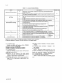
Table 5・1・2. Control Modes(MODE).
MODE
Set point
0
1 ’
,Set conditions
Default value
COLD start, The controller is restarted in manual mode, and manipulated output
kRecovery from power failure}
窒?starts from一・6.3%. ,
レ
1
gOT start. The contro闘er is restarted in exactly the same mode and status it was in
0
奄高高?diately before the power failure. ,
0
2
o回m・de}
h回mode, the data transmitted from a supervisory system is set as a setpoint.
2
3 0
■
CSC
0
ln回mode, the data stored in AI register is set as a setpoint, ’
1
O
oControl element 2 setting}
Cascade closed;the output signal of the first loop is set as a setpoint
?or the second looP.
1
SSC
Cascade open;the output signaI of the first loop is adjusted with
狽浮獅奄獅〟@panel pushbutton switches{SV2}. ’
Set when using
0
External second雄oop setting;the data stored in register A5 is set as a
bSC or SSC.
1
曾
0
唐?tpolnt for the second looP.
recond Ioop instrument setting;the setpoint of the second loop is
≠р鰍浮唐狽?d with加ning panel pushbutton switches{SV21. ’・
oSupervisory system backup}
0 .
4
When the supervisory system l「lfails, operation mode is switched
1
When the supervisory system{’11fails, the setpoint is held in auto{Al
ommuniationsw
高盾р? for automatic control. ’
奄狽? a Set when .
狽潤@manual{M}to enable controller output to be manipulate(些manually.
垂?rforming?
@ . ・s
5{
etting!operation by a supervisory equipment l●2}is enabled.
浮垂?rVlsory’s
凾唐狽?m.
Setting!operation by a supeMsory equiゆment(。21 is inhibited.
1Supervisory system:System, with which the computer or Operator station is comected.
2S叩ervisory equipment:Computer, CENTUM, YEWPACK orμXL Operator station.
し
3)TUNING switch
IR(dhect action):Deviatio11=Process variable−
Enables or l㎞hibits the functiolls of the TUNING
ushbuttoll switclles(厘1,團,囚).
Setpoint
NABLE:Settings and resetthlgs are enabled.
cess Variable L
NHIBIT:Sett㎞gs alld resettings are disabled.
5)ROM socket
4)ACTION s幅tches
Used to hlstaU the ROM containhlg the user
Se星ect the direction of control action between direct
rogram. The ROM c4n,be secured in position by
VS(reverse action):Deviation=・Setpoint−Pro−
DIR)and reverse(RVS). ’
urning the sodくet−10ck clockwise. Turn the socket−
IR1!RVS l:Set’the action of the basic contro1
丘10dule or the飯rst control element(CNT1)of the
0ck counterclockwise to dismount the ROM.
cascade or signal selector control module.
Used to connect the cable of a蹴SPRG.pτogram。
IR21RVS2:Set the action of the second control ele一
’ment(CNT2)of the cascade or signal selector con−
er.
trol module.
MIB4C2−04E
6)CONNECTOR(PROGRAMMER)
0.
5−7
Keyboard operation(See Figure 5−1−6.)
(2)Item number updating
The item number can be updated(increased)by
pressing the]N巨]key.
PROGRAMMABLE CONTROLLER
Display
5レ” 800
(Example of key operation and display)
XN key. Each・arrow mark indicates one key
operation.
」了粧」一一。A了A一一」
mボ蕊冨冒輔「
Item selection
堰?□□□i罫セll騨副2i□□□□ill礒蕊需
Xl−x∂ xヨ x早一一一x5
[二想二二二竺=△ニコ
(3)Data updating
The data value can be increased or decreased by
回回
「ご一、7一響一「「,□i□□□! L__________」
/Self−diagnosis
/
pressing the TUNING keys(団,囹,囚).
These keys are operative only when the TUNING
shde switch is set to the ENABLE position.
Data setting
囚:Increase data value.
囹: Increase/decrease data value fast. (Press con−
currently with囚or団.)
Item number updating
団:Decrease data value.
、,
(4) Self−diagllostics
Figure 5・1−6. Keyboard Fullctions.
The operating status of the controller can be
displayed and checked by pressing the CHECK
(1)Item(TYPE)selection
ALARM key. The method of display is idelltical with
Press the key of a des辻ed display item, and th「e
(1).See Section 5−7 for further deta皿s.
data type code(TYPE)for that item will be displayed,
(5)Display turn−off
along with its value(DATA). If more than one item
The display goes off automaticaUy approximately
has been assigned to a single key, the display Changes
30minutes after the last key operation. This el㎞i−
from one item to another each time the key is pressed.
nates unnecessary current consumption. The display
lights up again when key operation is resumed.
(Example of key operation and display)
①Pv/sv/Dv k・y. Each aπ・w mark indicates・ne
Unused signals and pammeters
key operation.
Input/output signals and parameters that are not
used tn the apphcation program can also be‘‘dis−
playeず’or‘‘set,’by keyboard operations;such data,
however, is irrelevant to, and has no effect on, the
②NONLINEAR key. Each arrow mark indicates
execution of control and computational functions.
one key operation.
巧κ’一石5’一Fロ’→5ロ’一ゆ月ロノ
−71一一乙[7’→Mll
lMIB4C2−04E
5−8
5。2.Preparations for Operation.
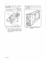
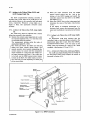
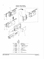
(3)To separate the internal assembly from the
housing, detach the connector from the as−
Make preparations with the coゴtroller installed in
sembly.(See Figure 5−2−3.)
the panel, or removed and placed on a work table,
(The controller is assumed to be in housing.)
Removing the internal assembly from the housing:
魯
(1)PuU out the internal assembly by pushing up the
stopper located below the front pane1. When it is
ノ
Connector
ノ
多ク”
“
drawn out halfway, the internal assembly is
restrained by an intermediate stopper. The
も
9 一・、
tunh19 Panel is funy operative at this stage.(See
Housing
Figure 5−2−1.)
lnte「nal
劉 薪
\じ。
assembly
三1。脳 !
o歴︶
Figure 5−2・3. Detaclling Connector.
5。2−1.Cllecking Special Parts Are Installed.
_60
一 齢
Check to see that the fuse, data−protect battery,
and、applications ROM are installed in the proper posi−
一
一ゴ1
o
.一σ
‘
L…琵
tions.
匹個
、り
一20
If any of them has not been installed, see Section
6−3,‘‘Parts Replacement,,, fbr installatlon procedures.
’1.・
r
回
q◎ 咽3
一
Stopper
5讐2−2.Preparations for Operation.
(1) Setting Lvalve open/closed indexes (See Figure 5−
2−4.)
ノ’
Position the valve open/closed marks,to agree with
Figure 5・2・1. Pu皿ing Out Internal Assembly.
the control valve action(direct or reverse).
The openlclosed marks can be removed manually
ノ
(2)To remove the internal assembly丘om the hous−
ing, push down the intermediate stopper spring
while pulling the assembly oμt f【om the housing
or by using a pair of tweezers.
回・CI・・ed(・・lve cl。、i。g di,e、ti・n)
回・OP・n(Y・lve・P・ni・g di・ecti・n)
as shown in Figure 5−2−2.
lntermediate stopPer spring
\
、
o
\
Figure 5−2−4. Setting Valve Open/Closed Indexes.
口
ノ
.爾,塑
も臼
o
Figure 5。2。2. Removillg夏ntemal AssemUy.
\
lMIB4C2−04E
5−9
〆
(.2) Setting the tun㎞g board(See Figure 5−2−5.)
set the DIRIRIv select switch on the tulling Panel
一一DATA一一一
oOmt
巳
口
to the requhred position.
DecimaI ● ■一幽
1
高高b??
Next, turn on the power, and set the TUNING
1
switch to ENABLE. Parameters can now be set from
the keyboard.
2
MOOEL SL.PC
τU網ING AC噛「60N
Note:
3
Decimal point is not displayed at
isplayed at
decimal point number 4 position,
Sposition,
4
ε髄AOしε 0旧1 D旧2
1鳳鳳鼠
(Example)Setting a scale range of−10.00 to 40.00
ROM
Key。in
Display
Description
唐?quenc?
1→工”o〃’o
オTYPF」LDATA」
Figure 5・2・5. Setting Select SwitcL6s.
囚
(3)Mode Setting
Current Hllvalue is dis−
垂撃≠凾?d in the DATA
・
唐?ctlon.
may be used團 CO刷currently.
H■’ 午θ〃θ
Call up the display MODE with a key operation,
口7’ o
and set the desired mode by pressing囚or団.
オTYPE」 LDATA」
(Display and setting 6xample)
Key‘in
MODE
●
唐?ctlon.
Display
唐?quenc?
Current LOI value is dis−
垂撃≠凾?d in the DATA
Description
団
乙θ’一’o〃’〃
∬円 ヨ.
二刀ε’θ
may be used團 co“currently.
Current DP value is dis・
p量ayed in the DATA
section.
阿[切ε’ 1
1f O is acceptable、
団
田
proceed to the next
1η戸’ ヨ
see the figure above.
g・weve馬use the囚,団
step.
M[7.刀ε∼ 1
”θ刀ど♂ θ
keys tO Change a Setting.
lf l is acceptable,
国⋮
proceed to the n『xt
st『P・
田 響囮
団
For details of decimal point,
♪
囚
H工1
月工∼
k[7∼
”口.刀εヨ 〃
』戸∼
@ …
Xl→Y1→HI1
For cascade or sdector
曹盾獅狽窒盾戟C the scale for the
唐?cond control element
高浮唐煤@be set in the same
way as for the first con−
狽窒盾戟@element.
N・t・・囚・・d団t・ke ab・・t 1・ec・・d f・・activati…
(5)Settillg other paτameters
lThis time is required to prevent faulty mode setting.}
Set all other parameters necessary fbr. control and
computation. Parameter−setting can be魚cllitated by
(4) Scale Setti119
Set the scale − fbr indicating the process var孟able
and setpoint in engineering units − in this order:
maximum value, minimum value, ahd declmal point.
Maximum value(Hlτ1):Set the value to be dis。
the use of data sheets. Table 5−1−11ists the parameters
and their setting ranges.
(Pammeter・setting example)
Setting the integral time fbr the second control ele−
ment to 600 seconds:
Key・in
signed 4digit integer.
唐?quenc?
Minimum val縫e(L口1):Set the value to be dis・
played when the internal data is O.0. Key in an as−
signed 4。digit integer.
Dec㎞al point(刀ρ1):Specify the decimal poillt
国,団 ・団
played when the intemal data is 1.0. Key in an as−
Display
TIl
sI2 18〃θ
V工∼ 50〃
position by its numbeτ.
Description
Current T12 value is dis・
垂撃≠凾?d.
@ may be used團 concurrently.
Otheτparameters can also be set l㎞the fonowi11g
.l
sequence:
①lt・m selecti・n・S・lect・d・・廿・d it・m u・ing・ne・f
the l l iten}(type)keys.
②Number updating:Update the item number with
the[正]key.
③D・t・・ett㎞9:1S・t th・d・ta v・1u・with th・団,團
an4囚keys.
iMIB4C2−04E
5−10
(6) Initial value,default value
b.Adjust the manipulated output signal by moving
Initial values can be loaded into ROM at the same
manual operation lever to the lef七〇r right.
time the user program is ehtered by using an SPRG
(See Figure 5−3−2.)
Prρgrammer.
If any data that was set from the keyboard is Iost
、
賢亀騨
、
due to a powel supply failure coupled with the lack
三1’。1
僧
一
9一
■
。の
一‘〇一
ROM is automatically loaded by CPU as a setting
o
P ●
極︺
1
of a data−protect battery, its initial va貰ue stored in
data and the cohtrol stalts.
Set−point up!down
Set−po
汲?y?
’
ら
匠『・
De飴ult values are the values wheh the programmer
麗「
一一餌
二一
and the paτameter are initialized while connected with
◎
the SPRG. When you create a new user program, be
sure to initialize the programmer and the paramete瓦
1
Manual
Manual operation
Iever
.一〇
﹂
鱈
’ ・『.
鱒1 .
(See「1旨bles 5−1−1 and 54−2.)
●
X’
一
一’,
回
回謬
See Thble 5−4・1 fbr STC parameters..
Set the parameters again if necessary.
’
彰・ ・
(7)Inchned moullting
Whell controller is mounted at an angle to the
vertica1, the indicator requires a zero adjust血ent. See
Section 6−2 for the zero a(恥stment plocedures.
When all preparations are completed, disconnect
Figure 5・3−2. Manua10utpu重Operation.
c.Set a desired setpoint by using the
set。POmt
up!down keys.(See Figure 5−3−2.)
the power plug from the controller, insta皿it in the I
pane1, connect I10 signa1.lines, and fina皿y apPly
power.
5。3・2.Alarm Checking and Tmnsfer to A耐。 Mode.
Assume that smooth response、characteristics have
been achieved through manual output operation and
5−3.Sta】rt−Up and Operation.
the process variable has reached a state of equ皿ibrium
at or in the●vic㎞ity of the setpohlt.
NOTE
(1) Al母㎜checking(See Figure 5。3・3.)
Th捻section explai血s the procedures for start−
up and operatioll of the contro皿er.
The procedures for start覗p and operation of
the controller may vary with the computation
and control programs used. The example below
illustrates s㎞ple PID control.
When the front−panel ALM lamp is o叫it indicates
that some signal line error has been encountered. De−
termine the cause of the error by qalling the CHECKl
ALARM item on the tuning panel and remove it.
Wllen the FAIL lamp’is o11, it indicates that a
fa皿ure has occurred ill the SLPC programmable
The rea4er.should fully understand the pro−
cedures described below befole proceeding with
controUer startup and operation.
indicatingσontro皿er itself.(See Section 5−5.)
(2)Transfer from manual operation to automatic
operation
P・e・sth・三二・d・t・ans飴r swit・h,・nd th・built−in
5。3・1.Manual Start−up.
illdicator lamp c6mes on to indicate auto mode is es7
(1)Manual opefation with the ma11μal operation
lever
a.Press the図mode transfer switch.(lts bu量t・ill
tablished. Mode transfers require no balancing opera・
tion, as they occur bump夏essly.
indicator lamp comes on.)(See Figure 5−3。1.)
客 甘
三鴨1、
一一一
=1_■o
/’一一”
蛋=7二﹂ ,
風■
Pushbutton sw
一
一1
一一〇
地〃,一
一9 ㌦ρ
﹂
1
.
㊤
■
回
!;二
n︳.一
PF
一 〇
= 100=竃====≡ 80======≡ 60===呂︸
eo.
唱︺
o
1
F直巳L
FAIL畳amp{r8d}
ALM
ALM Iamp{vellowl
、 、
Figure 5・3・3. FAIL and ALM Lamps.
Figure 5・3・1. Select㎞g Manual Mode.
lMIB4C2−04E
5−11
5・3・3.Normal Operation.
5−4・1.Self−Tuning Parameters.
(1) Operation mode transfer
Table 5−4−11ists the setti血g parameters which are re−
The SLPC programmable indicating controlle■can
1ated to the self=tuning ftmction. These parameters are
be switched from one mode to another by simply
P・essing th・回,囚,・・図m・d・t・an・f・・pu・h−
assigned to the ε晃 key oh the tuning PaneL ,
button switches provided that dh’ect transition from
(1)STC(Settillg STC mode)
図to回mode is prollibited. Mode transfersτequhe
STC mode is set as fbllows:
no balancing operation, as they occur bump16ssly.
(2)Parameter setting on the tuni119 Panel
OFF
Contro皿er parameters can be set or reset at the
The STC action is stoPPed.
0
user,s discretion by simply pulling the internal assemb−
New PID, values are displayed.{PID values are not
≠浮狽盾高≠狽奄モ≠撃撃凵@updated.1
1y out fヒom its housing and entering the parameters on
1
STC ON. PID values are automatically updated.
2
Automatic start−up」Refer to Paragraph 5鰯4・2.}
0.1
On−demand tuning.{Refer to Paragraph 5喝4−3.1
the tuning pane1. After parameter setting, set the
TUNING slide switch to the INHIBIT position.to pre−
vent accidental changes to the parameters.
For setting the STC mode, use the▼and▲keys
5−4.Setthlg and IDisplay of Self」Tuning Func−
on the tuning panel as shown be垂ow. Note that STC
ti6n.
=2can be set only in MAN mode.
▲key:OFF→0一→1一→2
The selfLtuning fUnction of the SLPC一口81 auto−
▼key:2一→1一→0一・OFF
maticany a(輸usts P, I and D parameters to their
(2)PB, TI, TD(PID parameters),
opti㎡um values depending on the characteristics of
These PID parameters are used in control com−
the controlled system.
putations. When・se1匹tuning action status at STC
=1,the initial setting automatically updates these
values.
賄ble 5−4・工. Names and Descri凶ons of Self」Tbrning Parameters.
Parameter values when each event is occurred
Wpe
Number
@ (N)
Name/description
STC
一
PB
1.2
Propor髄onal band
丁1
1.2
Integral time
TD
1.2
Derivative time
STC mode
Process response time
1.2
Noise band
OS
1.2
Desired response pattern type
Ml
1.2
NB I
1.2
1.2
奄獅奄狽奄≠撃奄嘯≠狽奄盾氏@with
@ RAM
@ RAM
rPRG programmer
魔盾奄≠狽奄撃奄嘯≠狽奄盾氏
魔盾撃%dilization
iNote 4)
iNote 5XNote 8) iNote 6)(Notθ8)
0
1
2
OF巴0,1、2
一
OFF
No change
0
0
○
○
○
一
6.3to 999.9
%
999.9
999.9
ROM initial value
ROM initial valuθ
○
○
○
一
PtQ 9999
sec
1000
1000
ROM initial value
ROM lnitial value
○
Oto 9999(Note 3)
sec
0
0
ROM initial value
ROM initial value
O
orocess type
.
○
O
O
O
O
Oj
一
0
No change
0
0
一
O
sec
300
300
ROM initial value
300
一
○
一
0.0
No change
0.0
O.0
一
○
○
一
一
2
2
ROM initial value
2
一
O
O
○
△
△
○
Engineeri口g unit equivalent to O to
@20%of the value set in SCALE
、 Oj,2,3
0.Oto20.o
%
5.0
No change
5.0
5.0
一
01.06
RB. high・lim鷺value
6.3to 999.9
%
999.9
999.9
ROM lnitlal value
999.9
唄
02.07
PB. low・limit value
6.3to 999.9
%
6.3
6.3
ROM iniliai value
6.3
一
○
03.08
lntegral time high−limit value
1to 9999
sec
9999
9999
ROM initial value
9999
一
○
04.09
lntegral time IOW−limit ValUe
1to 9999
sec
1
1
ROM initial vaiue
1
一
○
○
05.10
Derivative time high−limit value ・
Oto9999
一
O
○
MV. applied signal amplitude
一
O
4to 9999
一
一
一
O
一
○
ρ1.2
New RB. calculated value
sec
2000
2000
ROM initial value
2000
6.3to 999.9
%
999.9
No change
PBn value
PBn value
sec
1000 ’
No change
IA
112
New lntegral・time calculated value
1to 9999
DA
1.2
New derivative・time calculated value
CR
1.2
Probable error
RT
1.2
αstributed signal ratio
Tln value 「
sec
一
0.00
No change
0.00
0.00
0.000to 9.ggg
一
α000
No change
α000
α000
0
TDn value
1.2
Equivalent dead−time
Oto9999
sec
0
No change
0
1.2
Equivalent time constant
Oto9999
sec
0
No change
0
0
GM
1.2
Equivalent process gain
0.000to 9.999
一
0,000
No change
0,000
0,000
Note 1:
ROI to RO5 are limit values for PB1,TII and TD1.
Note 4:
Set PBn,Th, TDn, TRn, OSn and ROI to R10again.(n=1,2)’
RO6 to R10are llm置values fbr PB2, T12 and TD2.
O :Setting is required.
Nαe5=
SeヒSTC, IPn, NBn, Mh again.(n=1,2}
Note 6:
Set STC, IPn,TRn, NB日, OSn, Mln and ROI to R10again.(n=1,2)
一 =Set輔ng is not required.
Note 7;
1 :For display only 羊
Note 8:
△ :In on・demand mode
一
TDn value
LM
Note 2:
一、
slnvalue
Oto9999
No change I
一
1
0.00to 99.99
0
TM
Note 3:
OFF
○
舩
*AROM
Factory defau1吐
魔≠撃浮?s「o11NPR
○
iNote 1)
*EROM
Date se髄ing(Note 2)
○
唱
lP
TR
R
Unit
Display/seUing range
Parameter
The ROM initial value is a value when the program is written in user ROM while connected with the SPRG.
The user ROM using the function extended by SLPC曹E is called Il*EROM.1, The other user ROM is called”*A ROM.腿
,(For details, referto TI l B4C2。02巳}
Action range is 2‡09999 sec.(0&1:0FF)
lMIB4C2−04E
、
L
5−12
(3)
IP(Process Type)
This specifies whether the process is static−con−
0
Overshoot zero
1
Overshoot about 5%
2
Overshoot about 10%
3
Overshoot about 15%
trolled or integral−controlled. In an integral−con−
trolled process, when step input is applied, the
measured value is increased or decreased in行nite−
ly. Processes excluding the level control process
(4)
are almost a11 static−controlled.
(7)MI(signal applied to the MV)
TR.(Process 95%一response time)
When the STC is set to mode 20r the on−de−
This speci負es a 95(%一response time to a step input
mand mode, set an additionaレsignal that is ap−
in the process. STC controllers calculate the de−
plied to the manipulated variable(MV)so that
sired sampling time as well as time required to
the measured value overshoots by about 5%of
observe a measured signal wavefbrm.
the fUll−scale. When the STC is in mode 21t is
つ
Set an appropriate TR in the fbllowing ways:
①
Estimate the TR from the step.response
wavefbrm of the process.
operating manually. Therefbre, apply the MI so
L、
that the current contro11ed deviation is main−
tained. When the STC ls in the on−demand mode
つ
②
③
④
Set the TR to the time required fbr a process
it is in automatic operation. There負)re, apply the
variable change(△PV)until it reaches 95(殆
MI so that the controlled deviation decreases.
of the settling value. If the response time can
(8)R.01to RIO(P,1, D limit values)
be approximated with dead−time L and且rst−
These parameters can be used to limit the ad−
order−lag time constant T, TR=L十3T.
justable ranges of P, I and D parameters. If‘‘high
When the process is integra1−controlled:
Iimit value ≦ low Iimit value,, is set, the
When a pulse lnput is applied, set the TR to
parameter concerned is fixed at the low limit
the time required fbr a process variable
value.
change(△PV)until it reaches 95960f the set−
(9)PA, IA, DA(newl calculated P,1, D values)
tling time.
If STC== 0(fbr display only Of calculated P, I
Estimate from the continuous operating con−
and D values), the‘‘optimum”parameter values
ditions
calculated by the STC functions can be displayed,
Read the attenuation wave cycles Tp that are
but are not used in control oomputation. When
considered norma1, and set TR=Tp.
STC=OFF or 1, display㎞g、PA, IA and DA
When response time variations are estimated:
values results in the same values as fbr PB, TI
Select the desired response time. When the
and TD, respectively.
response time between an increase and a de−
crease in the measured temperature fbr fUr−
nace temperature measurements di脆rs, fbr
example, select whichever response time is
①Estimation from step−response waveform
MV
greater.
⑤
PV$ettlin
Notice:
value
1/200f the TR is the sampling period Ts fbr
PV
estimating the process, so a response wave−
fbrm less than 2Ts cannot be captured cor−
95%
rectly.
Generally, when the. TR ls larger than the
Tim
correct TR value, lt has fbwer process−charac−
TR
teristic errors. If the TR changes, data files
are initialized during a response time of 4TR,
so the STC does not operate.
②Estimation from damped oscillatory waveform
(5) NB(Noise Band)
Set the NB to twice the peak value of the noise
signal superimposed on the measured signaL The
TR=Tp
:NB is used to prevent the process from being inf一
PV
.luenced by a noise signa1.
(6) OS(desired responSe pattern)’
Set the type of desired response pattern(a criteria
Tp
Natural oscillation period
fbr selFtuning).
Time
ノ
]Figur65−4一:L
IMIB4C2−04E
Method of Estimating TR.
5−13
(10)
(11)
(12)
CR(Probable Error)
the manipulated output in the safb direction
An error when process characteristics are esti−
(to increase the deviation rather than reverse
mated. The STD controUer requires PID
its sign).
parameter settings when the CR is less than 5%.
The controller caluculates the se1塾tuning
RT(Signal Distribution Ratio)
parameters f士om the process response to this
This indicates the ratio of the PV distributed
step change.
value to the model distributed value. STC con−
When an STAL取I has occurred, the control
trollers c31culate a signal distribution ratio using a
mode may fa皿to switch to AUTO(CAS).
final model(STC l fbr the STC mode set to O)to
(Refer to Paragraph 5−7−6.)
五nd process−characteristic variations. When the
⑤When the plocess variable signal stab皿zes,
distributed value of the process signal matches
the contro皿er automaticaly returns the
that of the model output signal, RT is about 1.
manipulated output to its initial value.
When RT is greater than or equal to 20r when it
⑥When aU of the parameter settings are com−
ls less than or equal to O.5, an alarm occurs.
plete, STC mode is automatically switched
LM, TM, GM(Equivalent model)
from 2 to 1, and PID control starts. The
STC contro11ers indicate a simulated process mod−
囚t・回1・mp th・n・h・ng・・丘。m blink塊
el with an approximation of the‘ р?ad−time and
status to ON.
first−order−1ag system. LM, TM.and GM ihdicate
(4)Check items in conducting the automatic start−up
equivalent L dead−time, the equlvalent first−ofder−
①The process must be such that a 5%output
lag time constant,. and equivalent gain, respective−
change wiH have no undesirable e脆cts.
1y. For LM, TM and GM, respective values when
②lf process gain is high, and the process vari−
the STC mode is l and when the CR is 5%or
able changes by more than‘1.5MI96, the
less are retained. Calculated PID parameters are
manipulated output is automatically returned
related to PB, TI and TD.
to its initial value.
ノ
The CR is updated by the process characteristics.
③If process gain is low, and the change in the
セ
When the CR is greater than 5%, LM, TM and
process variable is Iess than 2%, automatic
GM are not updated.
start−up is considered inapPropriate, and after
5−4−2.Automatic Startup.
the maximum observation time(about 80
minutes)has passed, the operation mode
STC mode ls set to 2 fbr automatic start−up mode.
switches to MAN and an STC alarm is
In this status, the STC parameters(PB, TI, TD, IP,
孟ssued. ・
TR, NB, R)are automatically calculated by the step−
④The PID limit values(ROl to R10)are auto−
response method.
matically set to負)ur timβs(負)r high limit
‘(1)Applicable control modules
values)or 1/4(for low limit values)of the
BSC Basic colltrol module
initial PB, TI and TD values obtained by auto−
CSC Cascade control module
mat1.c start−up.
Available for the Secolldary loop with cascade
⑤lfapower f註ilure occurs duringautomatic start−
open
up, the operation mode is transferredto MAN
Available for the Pr元mary loop when cascade
.closed
(2)Setting Parameteエs
mode with STC=Oafter the power recovers.
⑥lfaSTALM(Re免r to Paragraph 5−7−6.)occurs
during automatic start−up, the start−up opera一
STC, OS and, if required, TD a『e set.
’tion is stopped and operation mode is trans−
Set TD=Ofor PI control.
ferred to MAN with STC=0.
TD is set to l or greate:r for PID contro1.
⑦If, during飢omatic start仰(with the囚
(Automatic start may res口lt in PI control.)
or回1amp blin㎞9),廿1e operation mode
(3) Operation、 prqcedufe
is switched to MAN, automatic start.up is
①First make sure that no STALM(Re艶r to Par・
stoPPed(STC is set to O).
②③
agraph 5−7−6)has occurred.
④
In MAN mode, set STC to 2.
5・4−3.On−Demand Tuning
Manually stabilize the process variable slgnal to
In the on−demand mode, an STC controller allows
an apPropriate value,
the operator to carry out self−tuning from the PV re.
Switch the cQlltrol mode to AUTO or CAS
sponse by applying a test signal to the MV value as re−
(automatic start−up begins).
quired.
Th・囚・・回1・mp・n th・f…t・fth・i・・t・u−
(1)Applicable condltions
merlt blinks.
An on−demand tuning operation is possible when
In automatic start−up mode, PID control does
the fbllowihg conditions.are all sat孟sfied:
not start fbr 30 seconds, but the controller
●When only basic control BSC or cascade con−
automatically apPlies a step change(MI%)to
trol CSC is selected.(When selector contro]
lMIB4C2−04E
5−14
SSC is selected, on−demand tuning is not
The PX parameter has the greater effect oll the roレ
available.)
Iow−up wavefbrm. The larger the value of PX、 the佑ster
●When the control operation is in the AUTO or
the rise time or the fbllow−up waveform. The PY
CASCADE mode.(When the DDC or SPC
parameter、 on the other hand, has a nlle adjustment ef一
mode is selected, onrαemand tuning is not
色ct−alld the larger the value of PY、 the s士naller the
available.)
Overshoot.
●When the STC mode is set to O or 1.
(2)Setting Parameters and operation
(1)Whell no self−tuning is provided:
●MI:Sets the amplitude of an applied test sig−
①Make a step change in the manipulated
nal. Set a value that overshoots by about 5(X)of
va■iable output, and calculate opt㎞um P, I
the PV. The MI is added to the MV value so
and D values from the response.
that the controlled deviation decreases depend−
②Make a step change in the set point, and
ing on the DIRIREV switch position and th6
a(異just PX so that the intended followup
current controlled deviation. For an integral−
characteristic is.pbtained. When derivative
contro11ed process, a pulse slgnal with an
action is provided, fine adjustment by PY is
︵
3abC
ロ ロ
d.
e.
5・5・2.Method for T㎜ing PX and PY.
●Set parameters when the STC is set to O or 1.
amplitude of TR/5 is added.
possible.
Operation procedures
③The recommended values of PX and PY are
Check that MI values are correct.
PX=0.5 and PY=0.0.
Check that the STC mode is set to O or 1.
(2)When self−tunlng is provided:
Press the[N】key once and check that the tuning
①After setting PX=0.5 and PY=0.0(recom−
request(‘‘RQ,,)comes up.
mended values), start operation using the
Then press the[NI key again. If the tuning re−
self−tuning function.
quest is canceled, press any key.
PX is optimized to provide the best response
Thus, the MI is added to the Mv.‘‘RQ,, wilI
to set−point changes;PID parameters are
blink fbr about TR/5 seconds. While‘‘RQ”is
optimized to provide the best response to an
blinking, the【N]key, even if pressed, is omitted.
external disturbance.
5−4−4.Display of Self・Tunh190peratio11.
6
Effect of PX
(1) Side tuni119 P allel
Wh㎝STC=Oor l and the selやtuning fungtion
PX=1.0
PV
PX=0.6
is operating,‘‘0,, or‘‘1 b丘nks. When STC=2
and start−up is being executed,‘‘2,, blin1(s. When
・ PX=0.3
either operation is stoPPed, or t1}e controner is inl
(PY=Ofixed}
MAN mode, the lamp on the tuning panel is lit
continuously(not blinking).
PX=0.0
(2)C,A, M mode display lamps(front of instrumellt)
While STC=2an4 during start−up,モhe C or
A lamp blinks.
Time
Effect of PY
●
5−5.Setting and Display of A{斯ustable Set−
Point Filter Function.
PV
PY=:0.0
\ PY=0.3
The a(萄ustable set−point filteエ(abbreviated as SVF)
(PX=0.5 fixed}
is based on a PI−D type control algorithm and is con−
Hgured so that filtering is added to the set−point part・
The ef〕陀ct of the filter can be a(加sted by two
parameters to continuously change the set−point fbl−
PY=0.6
PY=1.0
low−up characteristics between PI−D and I−PD.
SLPC一拍51 and SLPC一□81 are equipped with this
fUnction.
Time
Figure 5−5−1. Effects of PX and PY Parameters.
5−5−1・Effect of Changing the Fil‡er Parameters・
Figure 5−5−1 shows examples of set−point lbllow一ゆ
wavefbrms observed whell parameters PX(α)and PY
(β)are separately changed from O to 1.
lMIB4C2−04E
5−15
5−6.Automatic ContrQ1.
(2)一‘‘Proportiona1+integra1+derivative”controller
a.Set the operation mode to匝L and manually
When applying the controller to an unknown
adjust the process variable until it agrees with the
process, it is useful to e琴amine the performance of
set point. Set the integral time to 9999 seconds.
the process in manual mode.
Set the propbrtionala band to a suffic量ently wide
This can be useful in estirnating the proportional
band, integral time and derivative t㎞e required for
value, a圃set the derivatlve time to O seconds.
b.Set the operation mode to囚.・ ’
automatic mode.
c.Change the proportional band as d6scribed
For example, if a small change in the controller
above, and find the point where cycling just
output causes a large nuctuation 量n the process vari−
starts to occur. Measure the proportional band
able value, the width of the proportional band must be
Value(PBu)at th均point.and the cycling Period
increased (the gain must be reduced)to assure
(Pu).
stability. Conversely, the proportional band must be
d.The optimum settings can be determined as
narrowed.
follows:
For a process which responds quickly to a change
Proportional band=1.7 PBu
in the controUer output, the integral and derivative
Integral time=0。5 Pu
tlme constants must be short. Conversely, for a
Derivative time=0.125 Pu
process having a long recovery time, the integral and
derivative time constants must be long.
(1) ‘‘Proportiona1+integraP’controller
・.S・t th・・P・・ati・n m・d・t・図・nd m・nu。11y
The method explained above is called the Ziegler−
Nlchols threshold sensitivity method, and provides a
response characteristic\with approximately 25%
amplitude attenuation.
the set point. Set the integral time to 9999
Various a(巧ustment methods−such as the step−re−
seconds, set the proportional band to a suffici_
sponse method−have been proposed as alternatives
ently large value,.and then set the d臼rivative time
to the Ziegler−Nlchols method;please re飴r to tex一
to O seconds.
、
\
al工justs the process variable until it agrees with
tbooks on automatic control.
b.S・t th・・P・・ati・nm・d・t・囚.
c.Perform’the following operations to obtain the
optimumセaluefor the proportional band.
LoWer the proportional band in steps f士om a
sufficiently large value(for example,100%→
50%一>20%).Take a sufficiently long time for
each step, so that the control state can be fully
observed. Continue this operation until the
control loop begins cycling.(Cycling refers to
periodic osc且1ation of the process variable
pointer around the set po圭nt. This phenomenon
is caused by setting the proportional band,
narrower (setting the gain higher)than the
optimum value for the process.)The optimum
proportional band is approx’.2.2 times that of
the proportional band which causes such cycling.
Next measure the cycling period. The optimUm
integral time can be obtained by multiplyi:ng
this oscillation period by O.83.
Up to a poinち decreasing the云ntegral time
improves the control response. But, if the in−
tegral time is decre包sed past a hmit, which is
decided by the lag characteristic of the process,
cycling wUI start. If this虹appens, increase the
integral tirhe gradually unt且the cycling stops.
1MIB4C2−04E
5−16
5−7.Actionsωbe Taken When FAIL and
(2)Insert the cable connector from the SPBD
A正M:Lamps正ight Up.
mamlal control station into the ja6k at the
bottom of the SLPC housing a!1d switch the
The SLPC programmable indicating controller is
controller output from the SLPC to the SPBD.
飴rnished with a FAIL lamp and an ALM lamp to vis−
(See Figure 5−7−1.)
ually indicate failures童n the controller itself and signal
(3)Select the CHECK item on the tulling panel and
errors, respectively. Whenever a lamp llghts up or
determine the cause of the failure.(See Section
begins to flash, take apPropriate corrective action
5−7−4二)
promptly.
If the fa且ure is considered attributable to a
hardware fault, remove the instrument from the
5−7−1.Actions to be T劉ken wben FAIL Lamp Lights
panel and troubleshoot it as instructed in Section
Up.
7.
The FAIL lamp, when lit, indicates that a serious
fa迎ure has occuπed in the controller.
5−7−2.Actions to be Taken when AbM Lamp Lights
(1)Monitor the cuπellt outputlsignal a11d set it, with
Up.
the manual operation leve■, to a value that does
An illuminated ALM lamp indicates that the
not adversely af陀ct the prooess.
contro皿er’s high−or low−limit alarm is actuated or the
The measuremellt㎞dicator gives the value of
input!output signal line is open. Select the CHECK,
analog illput signal No.1(X1).
ALARM and STA、LM(SLPC一三810nly)items on the
The values just befbre the failure are he童d fbr
tulling Panel and examine the cause.of.the ala㎜
analog and status outputs during failure. The
condition.(See Sections 5−7−4 and 5。7−5。)
manual operation lever permits manipulating the
current output, but cannot hold the manipulated
output constant fbr a long time(the voltage ouレ
5−7・3.Actions to be Taken when ALM Lamp Flaslles.
put signal decreases with time). If the output has
the data−protect battery drops. Replace the battery as
to be held, use the SPBD manual control station
instructed in Section 6−3−4.
The ALM lamp begins nashing when the voltage of
to back up the SLPC. For either output, an incor−
rect value. may be held depending on which part
of the circuit failed,
8atterv
Check Button
./
r”
o ’,.’
ク
移ノノi
ク 〃,i7
Battery Check Point
、ぜ、
覧
●
%”
//
.:コ1
Selector Switch
/;’
/\、\
Housing
Connector Port
8
Contro鯉er
・」
Figure 5脚7・1. SP3]D Connection.
且MlB4C2−04E
o
、
B
o
’ .
嚢
画
/A
彪。巳.
Connector
炉\
Cable with
’
蕊.ジ
Adjustment lくnob
’
4イ
鰹謬
ManuaI
・、・ P
︽禿
Output lndicator
G
⋮N,i,
、■、&
Manipulated
o
ρ多/
”‘’
\浴こ
鮭
一
■・審
︾直
艦nput lndicator
5−17
︸
Notes:
5・7・5.AL,ARM Display.
(1)When the ALM lamp りegins flashing during
The alarm status of the control function ls dis−
normal operation, replace the battery immedi−
played as a 2−digit number. The ALM Iamp also lights
ately. ’
up・
(2)Anashing ALM lamp overrides a continuously lit
alarm lamp. No alarm status can be indicated,
(Display)
therefbre, while the ALM lamp isΩash1ng.(Other
alarms can still be displayed on the tuning paneL)
5・7−4.CHECK Display.
Alarm of first
cont「ol element
The CHECK display items are listed below:
CHECK
Lamp
Diagnosis
р奄唐垂撃≠
02
04
08
10
20
ALM
ALM
FAIL.
’ALM
Normal。
Fault in AID converter.
Fault in D!A oonverter.
Arithmetic range overflow.
40
FAIL
ALM
80。
PWR ERR
FAIL
一
High limit alarm
lnput signal overrange,
,
kow limit alarm
Deviation’alarm
Velocity alarm
Unmounted or failed User ROM.
Data protect battery not instalIed,
or(Lamp flashingl low battery
voltage.
ALM
Norma1
1
∂ 学 θ
01
FAIL
FAIL
Diagnosis
ALARM display
〃
00
一
Alarm of second
COntrOl element
If two or more alarm conditiobs occur at the same
time, the total of the individual values is displayed
(sum of their hexadecimal values).
Current output signal line open
or overloaded.
(Examples)
RAM memory data lost砦.
SupPly voltage too low.
月L月月M
〃5
Microprocessor faulty
《display not possible}.
軸Avalue of 80 in the display together with an illuminated
ALM lamp foliowing a power failure{after power applica−
6=2+4(Low−limit alarm+Deviation alarm)
月L月尺M
ε5
tionl indicates the occurrence of power failure.
When 80 is displayed, check the PID and other parameters
on the side panel since they have been initialized.
The display of 80 during normal operation indicates a
failure due to the loss of internal data.
E=2+4+8(Lowrlimit alarm+Deviation alarm
+Velocity alarm)
5=1+4(High−1imit alarm+Deviation alarm)
The display returns to OO when the alarm condi−
If two or more faults occur at the same time, the
tions are removed.
displayed value is the totar of the individual display
/
values(sum of their hexadecimal values).
(Examples)
」
だ月ε[κ 口[齢
OC=04+08(Computing range overflow十
Input signal overrange)
ε月ε[:κ 月θ
AO=20+80(Battery low+Data lost)
The display value returns to OO upon removing the
cause of the fault. The value 80 jn the display(ihternal
data lost),does not return to OO automaticaUy;use the
[f] key to reset the di寧play.
1MIB4C2−04E
5−18
5−7−6.STAbM Display(SLPσ□810nly).
Examples二
STALM is assigned to the 鮒鼠9鳳 key alld, whell
the self−tulling function cannot operate normally, dis−
5τ月1乙M
plays STALM status using a 2−digit number. Table 5−7−1
05
shows the diagnoses which correspond to STALM dis−
play eodes. The ALM lamp also lights up.
,6=2十4(PID values af limits,
Whell two or more alarms occur simultalleously, the
manipulated variable output stuck at且imit)
sum of the individual alarm display codes is displayed
(i.e., addition of hexadecimal numbers).
5丁月乙岡
E』
EO=20十40十80(STC mode switchlng, current
output open, process variable input over−range)
The dispiay value returns to O as soon as the corres−
polldhlg alarm retunls to norma1.
Table 5−7−1. Self−Tuning Alarm Display Items.
STALM
р奄唐垂撃≠
00
STC
Diagnosis ,
高盾р
All
01
Normal{always OO when STC=OFF}
O There has been an attempt to use a control element
STC action
To clear alarm
Continue
一
StOP
whose use in combination with STC is prohibited. ・
O Control module is not executed every period.
02
O P,land D values are at high or low limits.
O Remove cause
Continue
of alarm{s}.
O Control samples set in self−tuning functions do not
match press conditions(where RT:≧20r RT≦二〇.5}. 一 一
0.1
04
O Current.output open.
StOP
O The manipulated variable output is Iimited by the
@ output Iimiter.
08
O Process variable input value is out of range.
10
O There has been an attempt tq use a control module/
.
bontinue
O Turn STC OFF
n Press[N]key
Continue
element whose use in combination with STC is
prohibited.
O C6ntrol module ls not e×ecuted everV period.
O ln,CSC mode internal cascade loop was opened or
c16sed.
20
O Rest STC= 2
O Acommand to change the STC mode or turn off STC
action was issued by a user program or manually.
O Turn STC OFF
,
2
40
n The operation mode was transferred to BACK UP
@ MAN st自tus.
O Power failure。
Transfer to ,
lAN m.ode,
O Current output open.
O There is a possib爾tV that a step change in MV.may
cause the output value to reaqh the筒mit value or MV
over range・
80
O Process variable input is out of range.
O The ch自nge in the process variable was too small for
observation time(about 80 minutes}has passed).
lMIB4C2−04E
n Press[団key
STC=0.
O Must remove
StOP
cause of alarm
5−19
5−8.Connecting an SPRG Programmer.
5・8・2.Disconnecting the SPRG.
(1)
Set the SPRG in PROGRAM mode.
Use an SPRG Programmer to change set data or
(2)
Turn off the SLPC.
control programs stored in the controUer.
(3)
Turn off the SPRG.
Re免r to the. SPRG Instruction Manual
(4)
Detach the SPRG cable connector from the
(IM lB4W1−02E)負)r detailed SPRG operation infbr−
SLPC.
’
matlon.
This section explains how to connect the SPRG
Programmer to the SLPC programmable indicating
controller.
/三一・
匪囚印
CAU’「10N
Never attach or remove the SPRG connector
from the SLPC while power is being supplied.
7
/
つゆ〇
6
Alingnment
MarkS△
M
三〕ピ〕o
つ。
つ〔〕o
5−8−1.Co.㎜ecting t車e SPドG.
(1)
Turn off both the SLPC and SPRG.
(2)
Set the SPRG in PROGRAM,pde/
(3)
ヒ
Attach the SPRG cable connector to the SLPC.
︶︶5
4
︵︵
(See Figure 5−8−1.)
Turn on the SPRG.
SPRG
Programme「
Turn on the SLPC.
Figure 5−8−1. Connecting the Cable to the SLPC.
lMIB4C2−04E
、
6−1
6.MAINTENANCE.
This chapter explains the SLPC Programmable
(5)If the tolerance is exceeded in(4), apply 3.O V
Indicating ControUer adjustments and parts Ieplace・
DC again and make fine a(加stments with the
ment procedures.
reading to fit in the range of 50〔シ6±0.5%,
(6)Repeat(4)and(5)unt皿the read㎞gs at a11’input
6−1.Test Equipment.
poillts are held within the tolerallce.
DC voltage!current stalldard;
Yokogawa Electric Corp. Model 7651
0r equivalent ...................... 1unit
SPRG Progra耳nmer..................1unit
o
6−2.Test, Calibration, and A(加stment.
o
、
6・2−1.Generat㎞g a Mahltenance Progmm.,
心、
Connect the SPRG pτogrammer to the SLPC
controUer, and generate the following Progra】m:
o
(Maintenance program)
01
02
Lbx2
STA1
03
LDX1
04
BSC
05
06
LDX3
STY1
07
END
回
Program
四
一匹
Step
No other operatiolls−such
as parameter settings−are
required.
Figure 6・2・1. Zero Adjustment of Measurement
PO㎞ter.
6・2・3.Zero Adjustment of Setpoint Index(Moving
Coil Veπsion).
(1)Apply a voltage of 3.O V DC to㎞put terminals
X2(te㎜inals 3(+)and 4(一))from the DC
voltagelcurrent standard.
After preparing the p士ogram, set the SPRG pro−
grammer in TEST RUN mode, set MODE2 to l on
the SLPC contro皿er tunh19 Panel, and press the
回mode transfbr pushbutton switch. Then carry out
the負)110wing a(加stments:
6・2・2.Zero Adjustment of Measurement夏ndicator
(Mo▼ing Co皿Version).
(1)Apply a voltage of 3.O V DC to process vadable
input・telrτninals X1 (terminals 1 (+)and 2 (一))
from the DC voltage/current standard.
(2)Check that the measurement pohlter圭ndicates
50%±0.5%of the caHbration mark on the scale
plate.
Standard screwdriver
(3) If the reading is not in this range, rotate the zero
adjustme飢screw to point to 50%, as shown in
Figure 6・2・2. Zeπo Adjustme耐.of Setpoint Index.
正ligure 6劇2−1.
(4)Change the input signal to l.OV,2.OV,4.OV,
and 5.OV DC, and check that the readings are at
O%,25%,75〔ゐ,and lOO%calibration marks, re−
spectively. The tolerance is±0.5〔レ60f span.
Check each calibration mark at the positlon where
the line of sight and set−point value indicator are
horizonta1.
lMIB4C2−04E
6−2
(2)Adjust using the same procedure as described in
steps(2)through (6)for the measurement
⑱ N
pointer zero po血t(Section 6−2−2). Figure 6−2−2
0
9旺10
囎
⑦.0σ
shows how to adjust the setpoint index zero
0
⑨
point.
0
6−2・4.Adjusting Fluorescent Bar Grapll Illdicator.
The fluorescent bar graph indicator requires no
⑪
zero a(巧ustment fbr either the setpoint index or input
Eコ]団[=羽
indication. Perfbrm only steps(1)and(2), Section 6−
_グ_
0
e
e
2−2.
6−2−5.Zero Adjustment of Output Indicator.
Standard screwd肖ver
(1)Apply a standard voltage of 3.O V to input termi−
1
nals X3(terminals 5(+)and 6(一)from the DC
’
voltage!current standard.(Keep current output
ノ
terminals A(+)and B(一)shorted.)
(2)Make sure that the output index is jllst on the
main scale mark in the middle。 The tolerance is
±25%(equivalent to 1120f each scale division.)
し
Figure 6・2−4. Zero Adjustment of Output Indicator.
(See Figure 6−2−3.)
Check each main scale mark at the position where
the line of sight and output indicator pointer are
6・2−6.Inchned Mounting.
In the case of an inclined controner, set it up at
vertical.
the actual mounting angle and a(巧ust its measurement
pointer and setpoint index zero points as instructed
in Sections 6−2−2 and 6−2−3.
Output indicator pointor
6・2−7・Brightness Adjustment of F真uorescent Bar
Graph Indicator.
1川Illllll川1川ll
0% 25% 50% 75% 100%
Adjust the brightness of the fluorescent bar graph
when it is low.(See Figure 6−2−5.)
Note:Excessive hlcrease in the brightness could have a
harmful effect on the fluorescent tul)e lifb.
[
<kコ くコ
【〉 じ寵〉
[
(3)If the index deviates from the tolerance, rotate
’
、て
Figure 6−2−3. Output In“icator Mahl Scale Marks.
o
薩緬
り
’
o
〔コ
一
(4) Change the hlput signal to LO V,2・O V,410 V,
瑚
points to the O%,25%,75%, and 100%points
o
’
’
’
“
accordingly. The tolerance is±2・5%of span(112
回
(5) If the tolerance is exceeded in(4), return to step
論
∼_泥
o
P
.・凝
\
and 5。O V DC, and insure that the output index
0f each scale division).
9
留
Figure 6−2−4.)
・80
,・●o
、
’
o
、
points to the middle main s¢ale graduation.(See
巨︺
the zero−adjustment screw so that the index
四
Standard screwdriver
(1)and make fine adjustments with the reading
to fit within the tolerance.
(6) Repeat steps (4) and (5) as necessary untn
the readings at aU points are held within the
tolerance.
lMIB4C2−04E
Figure 6−2−5.
Brightness Adjustment of Fluorescent
Bar Graph Indicator.
6−3
6−2−8.Digital Display Sett血1g.
Note:The eight−position DIP switches should be set with
Scale plate
闘
your finger nail or small screwdriver.
OFFIし,
The fluorescent bar graph version has a fbur−digit
This is an example switch
setting。 When the switches
≠窒? set as shown,values frdm
0・Oto 100.O are displaVed.
0簡
一一
the fヤont panel.
The numeric value displayed on the digital display
@・100 一
@ 。FFI9}
display on the right side of the bar graph indicator on
,
■■■一 ●
黶@ 尉 の 可 の O h O◎
一一一 ・80
corresponds with that displayed on the bar graph
indicator scale.
一
’1、
’ 、 ,
@、
@ 1 0N
。■国一 ■
一
setting must also be changed by the following pro−
ロー
、
@・60︸
When the scale plate is changed, the digital display
’ OFF㈹
n r7 調 u2 卜噛 oo
cedure.
■■勝一一 ●
一
ト日
OnH
O日月U
で日
ワ日
ZO﹂﹂O
卜日
0日
⑩nHHU
ZO﹂﹄O
四nU
炉RU
O日
噂日
O日
SW2(R)
O日
NnH
SW 1(L)
This
indicates the direction in ;which the switch must be set.
o◎
Figure 6駒2。7.
DIP Switch Setting Direction Marks
Printed on Scale Plate.
(5) If the value displayed on the fbur−digit display is
一,
易 ノ・77
髭グ⑱膠’ !4璽・ノ’ 廻
to be displayed on a dif艶rent range from the indl−
m;ノ
cator scale range, set the 8−digit DIP switch as fbl−
一
b撃
回q・ りb ◎
,吊譲轟…ii
a.Select the des±red display values(minimum arld
奄奄奄奄奄奄奄於ォ繊
奄奄奄撃堰c⋮⋮⋮⋮li撫ill’.,i⋮⋮⋮i⋮i⋮⋮⋮i⋮i難⋮︳i..ii・・.∵.1”冠・㌣
19一﹁
傭O6
Al
31嚇「一
maximum values)from Table 6−1.
糖li:ili:i;i
@∼幽
@ oレ滋.
60
1
亟廻,
//■
粕
@即
10ws=
Oo
’ 一 ・10〔
@ 』
潤@ ■
@ 1:
@ ’
b.Set binary values which correspond to these
mlnlmum and maximum values on SW1(L)and
SW2(R). Nos.1to 70f SWI(L)are used for
setttng the minimum value, and Nos。2to 80f
o ㊨
SW2(R)are used to set the maximum value.
Cover
Notes:
1.Values outside those given,in Table 6−1 cannot
0
be displayed.
2.The display range of the four−digit display
unit is一・1999 to 4999.
Figure 6−2−6. Eigllt−Position DIP Switches.
︶︶
︻∠
︵−晶︵
3.The reading jh the four−digit display unit is
(3)
(4)
Remove the cover as shown in Figure 6−2−6.
linear工n relation to the㎞lput(1 to 5 V DC).
Two 8−position DIP switches(L and R)are
(6) Decimal Pojht Position(D.P.)Setttng.
located side−by−side inside the cover.(See Figure
When the lbur−digit display values include decimal
6−2−6.)
points, a separate decimal−point setting is required in
The DIP switch setting direction marks are
addition to the maximum and minimum value setting
pri亘ted on the scale plate.(See Figure 6−2−7.)
descr孟bed above.
Set the DIP switches according to the indicated
Set No.80f SW1(L)and No.10f SW2(R)as fbl−
setting positions so the digital display conforms
lows depending on the decimal point position required.
to the scale graduations on the scale plate.
(See Figure 6−2−8).
、
、
1MIB4C2−04E
6−4
9h質eSh
,lW
010101010101010101010101010101010100011001︼00!正001100110011001100110010000111100001111000011L100001111000
D。P.Setting Switches
●
1111000011110000︼111000011110000111111110000000011111−110000000011111111000011−111111111111100000000000000001111111111111111111︼0000000000000000
111−−1!1111111−111110000000000000000 .
.9000000000000000000000000000000000009000000000000000000000000000000000009987654321098765432]01234567890123451ーユエーユー11ーユ00000000POOOOOOOOOO1111i1一=二=二===︷二:︸ 圃
located after the fourth digit
Ct
Notθ:The decimal poht poゴltion cannot be changed
for both the minimum and maximumvalues.
00000000111111110000000011111111000
1
1
1
1
1
1
1
1
1
1
1
1
−
1
1
1
0
0
0
0
0
0
0
0
0
0
0
0
0
0
0
0
1
1
1
0
0
0
0
0.
00
00
00
00
00
0
1
1
1
1
1
1
1
1
1
1
00
00
00
00
0
0
0
00
00
01
01
01
01
01
01
01
00
0
0
0
0
0
0
0
0
0
01
01
1
The decimal point position is
PID
00000000000000000000000000000000009000000000000000000000000000000000096789012345678901234567890123456789911董1 2 2 2 2 2 2 2 2 2 2 3 3 3 3 3 3 3 3 3 3 4 4 4 4 4 4 4 4 4 4 4 ,
[工=ロコー□=[□]コココ
locatod aftor thθthird digit
9ht
0
00
11
0−
−0
00
11
01
10
00
11
01
10
00
1−
01
100
01
11
01
0
01
10
11
00
01
10
11
00
01
10
11
00
01
10
11
00
一ロコ]=[工]ココ
The decimal point position is
te
一 さ」 驚 マ u= qつ e㌔ OG
一 N ぐマつ 「守 u驚 qつ e㌔ oc
1
0
→
†he decimal point position is
located aftθr thθ5econd digit
ShC吐WS
SW2(R)
SW1(L)
Four。digit Display Unit
S
PlD
Figure 6−2−8. Decimal−Point Position Setting.
﹁
lMIB4C2−04E
0
[エコココー
No. Decimal Point
Display Values Given by I)igital Display Unit and
Table 6・1.
Coπesponding D1P Switch Settings.
6−5
6−3.Parts Replacement.
6。3・3.Replac血1g the Fuse.
If it 6eems that the fuse may be faulty, check the
6−3・1.Replachlg tlle Nameplate.
inside of the fuse ho1αer for contamination or poor
Pull the internal assembly out shghtly from the
contact with the use.
housing. Open the top hd of the internal assembly,
RecQmmended.replacement interva1:About 3 years
and rβplace the llameplate.(See Figure 6−3。1.)
(1)To remove the fuse, unscrew the fuse holder cap
(turn it counterdockwise in the direction of the
arrow);the cap and fUse can then be remo》ed.
(2)Ihstall a new fuse of the coτrect rating. Tighten
the cap firmly.
Note:Use the dedicated fuse(S9510VK). Do not use
afUse fbr other products.
ミ
﹁
\
一
coo・薗
1!
、
.ミミ藁
︸
Figure 6−34. Replac血g Nameplate.
6・3−2.Replaci皿g tlle Scale Plate.
Opell the top lid of the internal assembly。 Remove
the scale plate retaintng cap*using a small regular
screwddver.
Fuse Part No.:S9510VK
To remove the scale plate, use tweezers as shown.
Rating:1A
Insert a new scale plateうand put the cap*back in the
origi血al position.(*Moving−coil version only)
Figure 6・3−3. Replacing the Fllse.
(Scale Piate Hand瓢ng Instructions)
o Keep fingers off the scale side and the back side of
6。3・4.Replacing the Data置Protect Battery.
the scale plate.
Replace the data−protect battery immediately
o If the scale plate is stained, wipe it using a soft
when the front−panel ALM, lamp begins flashing.
cloth.(Never use alcohol or other original solvents,
Recommended replacement intervals:
which could also remote the markings on the scale
About 5 years(charging, at ambient temperatures
plate.)
below 45。C)
About l year(shelf−hfe, at ambient temperatures
亘eiow 45。C)
CAUTlON
Leave the power on in the controllgr while rep−
\
幅
へP
並﹃ミ 1 、
1acing the battery, If the battery is removed
while the power is off, some data(parameter)
. ■層一=3一
settings will be lost.
黶@一80
Cap
−
一 ”り
一’
「創L
housing, and remove the battery cover and the
愉
’’,0 層
in position.
飢飼
battery.(See Figures 6。34 and 6−3−5.)
(2)Insert a new battery and mount the battery cover
S三τ
1
(1)Pull the interna}assembly out slightly from the
B 曾
一白
o
20一
同日︺
P
1/イ
(3)Insure tha亡the frollt−panel ALM lamp stops
・flashing.
Figure 6・3−2. Replac㎞g the Scale Phte.
1MIB4C2−04E
6−6
(Handling Care of the Data−Protect Batte『y)
(1) Storage conditions
Amblent temperature:一10to 60。C.
﹁
Ambient humidity:5 to孚5%relative humidity
(non−co11densing).
(2)Where possible, replace the battery with its case。
Be sure to observe correct battery polarity when
installing just the battery itself.
0
冠’
瓦
塾ル
Location free from corrosive gases.
、
で
(3)When measuring battery voltage, be sure to use a
4
high−input impedance voltmeter. Never measure
!
.ノ ,
voltage with a circuit tester or the like.
o
Voltage:2.45 V or higher.
、諺、 ! , 〆6 .
‘ぎ習曜7閏一
劉齢.= ;γ・麟 A .し亥見一1
◎『 ・晦 同
/
0
劣
? ク
Figure 6−3・5. Removing the Battery.
@彪
@◎
ソ
● Cautions against Static Electricity
Be sure to use a conductive mat when carrying and
storing the PROM device. Do not bring it into contact
@ o ’
潤@》
with clothes and other substances that can be charged
easily.
Do not handle the PROM using chemical fiber
gloves.
0
●Protect from Ultraviolet Rays
Figure 6−3・4. Removing the Battery Cover.
︵
when it is necessary to erase its contents.
︶OOOOO
4
Do not remove the seal from the PROM except
Cautions in handling batteries
When installing a new PROM in the controller, be
Do not recharge batteries.
sure to affix the specified seal to it.
Do not heat or dispose of batteries in a fire.
● Do not Damage Pins
Do not short together the positive and negative
If the pins are bent, straighten them while being
poles.
carefUI not to apPly fbrce to the base of the pin.
Observe correct polarity when insta皿ing.
Do not apply’ 唐?ock;do not attempt to dis。
assemble.
6。3・5.Replacing User ROM.
CAUTION
Do not attempt to install or remove User ROM
while the controller is energized;otherwise,
the controller.may switch to FAIL mode, and
the ROM may be damaged,
(H:andling Care of the User ROM)
User ROM is a PROM−aMOS(metal oxide
semiconductor)IC. This type of IC must be handled
carefu11y, as it may be damaged by static electricity.
Note also that the program written into it will be lost if
the ROM is exposed to ultraviolet rays through the
window on the top of the device.
Note the fbllowing considerations when handling
User ROM:
lMIB4C2−04E
Figure 6。3・6. ROM Seal.
6−7
/
・N
’
随藷
一ノ
」.【曜一〆
’湾
28Pin
8
iROM Lock
琶
鯉‘艘
●
‘5哩α岬
■
脚
oC
ol
ノ
24Pin
匠〕㊧〔図面
@ User ROM
匡〕【己ε〕〔扇
面匠〕〔己㊧
面㊧〔己㊦
_R。M.S。。k
,1・多ノ咀
ニニノノ
Cover plate
Figure 6−3−7. Removing lTuning Panel Co▼er Plate and ROM.
To replace User ROM to supPort program challges, 6−3。6. Replacing the Fluorescent Bar Graph.
.graph
proceed as follows: The丑1umination of the fluorescent bar
(1)Removing User ROM
display decreases with time. Adjust the display for
a.Turn off the power to the controller.(Leave the
optimal illumination with the,side−panel brightness
data−protect battery in position.)
adjustment vol}1me. If such adjustment is difficult,
b.Remove the tuning panel cov6r plate;User
replace the bar graph.
ROM will be exposed.(See Figure 6−3−7.)
Recommended replacemellt interva1:About once
c.Using a small standard screwdriver, turn the
every 3 to 5 years depending on conditions.
ROM lock on the ROM socket counterclockwise
See Section 7−2 for the replacement procedure.
1/4turn.
d.Grasp the ROM manually and pull it out of the
socket, being carefUI not to damag6 the pins.(See
Figure 6−3−8.)
(2)Installing User ROM
a.Turll off the power to the controller.(Leave the
datarprotect lbattery in position.)
b.Install the new ROM with its recessed window
facing’up.
c.Insure that the ROM pins are correctly aligned
with their corresponding .socket positions.
ド
When installing a 24−pin ROM, the two pairs
of pins in the top socket should not be used(see
the mark beside socket).
d.Press the ROM carefully into position.
e.Using a small standard screwdriver, turn the
ROM lock on the ROM socket clockwise until
Figure 6・3・8. Removing ROM.
it stops turning(apProximately 1/4 turn).
1.MlB4C2−04E
7−1
7.TROUB:LESHOOTING.
If operational troubles occur in the SLPC
Programmable Indicating Controner, identify the
problems fully and resolve them according to the
Troubleshooting can be facilitated by the use of the
troubleshootj㎞g flowcharts shown in Section 7−1.
YOKOGAWA service center serving your area.
7−1.
extension cable contained in the service−kit(SSKD).
When the trouble is dif丘cult to locate, consult the
Troubleshooting Flowcharts.
(1)Problem Identification
lnstrument
faiIure
Totally
YES
To(2}
inoperable?
NO
lS
FAIL!ALM Iamp
YES
FAIUamp is lit
To(3)
ALM lamp is Iit
or flashing
To《4)
C/A!Mmode transfer
disabled
To〔5}
lit?
NO
Setting!
manipulated
YES
disabled?
Setp◎int unchanged
NO
To.{6)
Output operation
lndicator
YES
disabled
To(7)
failure?
NO
Tuning
panel failure?
YES
τo(8}
NO
Input/
output signal
YES
Contact inputloutput
To(9)
signal error
error?
Analog input!output
NO
Communト
To《10}
signal error
YES
To(111
cation error?
NO
Start
YES
To(12)
mode failure?
NO
Recheck
Power doウvn for at Ieast
ヨ
2seconds, then power up
and recheck the problem.
1MIB4C2−04E
/
\
7−2
(2) Totally Inoperable
Check connection
between internal
.assembly and housing
YES
IS
fuse normal?
NO(blown}
7
Replace fuse
…ebl・w・ag…
Repla停e housing
p一ニー一
一「一一一
Faulty power supPly
unit;replace
lMIB4C2−04E
k麗翫鰯紺
7−3
(3)FAIL Lamp is Lit
lS
CHECKdispl合y
NO
available?
YES
NO
CHECK=00
YES
NO
Normal
CHECK=01 =02
」
operation?
YES
CHE…CK=10
《One probable cause
of the malfunction is
NO noise.)
YES
User ROM not
(Only the FAIL
’insta脛ed or faulty
lamp is faulty。}
Power off for at
{・》
NO
least 2 sec。, then
check again
ls
CirCUit VOItage
normal?
YES
Faulty power unit;
replace
Replace I/O card
Ifnormal operation
is not restored, re−
install original l/O
一 一一 一r 一 一 一
Replace display unit、
lfnOrmal Operation is not restored,
reinStallOriginal display unit
card
Faulty l/0 card;
replace
◎Check to see that the voltage across User ROM pins
12and 24 is ln range 4。8 to 5。2 V.
lMIB4C2−04E
∫
7−4
(4)ALM Lamp is Lit or Flasb㎞g
YES
Check power supPly
voltage
一一
ls PWR ERR
YES・
displayed?
NO
o臨瀧1一幅
YES
CHεCK寓00
Change the power unit
NO
YES
Remains lit
ALARM=00
1mp「OPO「P「ogram
YES
NO
CHECK冒04
pa「amote「s
NO
YES
Process variable
signal alarm
CHECK昌08g富40
NO
lnput signa馨or
current output
signa60rror
CHεCK昌20
…奪織繍1㎝
Check CNI and
othe「connections
YES
Replaco battery
〔voltage=2.45 V or
higher,
NO
CHεCK=80
u一・・
YES
p一
Press「↑」,1:henl
recheck
NO
Problem persists
(CHECκ昌OCCHεCK電AO ● ■ 9 ● ●)
Ch6ck CN4 and
othor connections
決鼈
一 一 椰
〆
…bl・m…s・・t
Fau塵tv l!O card;
See Section 5軸7−4
replace
for multiple errors
Replace d:splay unit
麗羅鰐馨綱一一一∠
Faultv main card;
replace
lMIB4C2−04E
\
7−5
(6)Setpoint or Manipulated Output Uncllanged
(5)c1AIM Mode Transfer Disabled
Manipulated output
Are
C!A/Mopera−
tions norma17
NO
(mode transfer
disabled}
Can
output be increased!
YES
decreased?
Setpoint
YES
NO
Operatbn mode
垂窒盾垂?rlV
1:ransfers’
but Iamp indica・
tion is abnormal
Power down for
at least 2 sec.,
then power up
and recheck
趣欝.n
YES
Can
setpoint be increased/
decreased?
量ndicator
failure
NO
To(7》
Are set−
Check CN4cQnnection
point and manipulated
outPut operable from
NO
Does operation
mode permit
tuning panel?
manipulation?
YESl
一門鼎・・n
Replace displaV unit
Check回!囚!匝}
MODE 2、3
Replace display unit
…儒総i憲躍榊声
一一
ユ膳満載。n
lS
FAILIamp
YES
Faultv l!O card;
replace
lit?
NO
キ
To{3)
Faulty 1!O card;
replace
瓦
lMIB4C2−04E
7−6
(7)Measurement Pohlterlsetpoint Index Error
YES
ls
(Check SV and PV
indication
indications on the
tun董ng paneL)
unstable?
(8) Tun血1g pa亘el fa皿ure
Check回!囚!回,
MODE。 and tuning
switchl setpoints
NO
IS
indicating error some−
YES
NO
what erratic?
lS
display normal?
NO
YES
Zero adlustment
(See Section 6。21
一癖盤謝・㎞佑
Power off for at least
2sec., then recheck
=奪黒繍㎞
NO
NO
lS
item selectable?
lsanalOg
output normal?
YEiS
(Check Y2, Y3}
YES
To(101
NO
Replace display unit
Can
settings.be changed?
YES
Recheck problem
Faulty CPU card3
replace
、
lMIB4C2−04E
7−7
︶
10ノ
︵
Contact Output Signal Error
(10)Analog Output Signal Elror
YES
ls lnput/
output disabled?
Replace housing
NO
、
fnormal operatiOn is
一一一
not restored reinsta踊
original housir19
ヲ
Replace housing
Check CNI and
朧鵬bn)…
other connections
一一
猪│ati.nls
Check CN1
connectlon
サ
Faulty l10 card;
騙贈L鼎on)一一一
replace
Signal value error
NO
YES
(Check tunhg panel
for errorσer「atic
indication, etc.)
Recheck problem
Replace I!O card
\
lMIB4C2−04E
7−8
(11)Commun三cations Failure
Communications with SCMS
Cρmmunications with supervisory device onlV
Communications device
(via LCS card)
devlce only
[
翻講繍…
Ch.eck SCMS
Check SCMS
communlqatlon mode
(MODE2=11
dommunication mode
(MODE2窩2)
Remove or replace
Replace SCMS
SCMS
Observe problem on
UOPS(COPSV}
system message panel
Normal?
NO{FAIL}
飼CARD
ERROR岬?
YES
YES
Normal?
NO
NO
YES
(LCS or following
\
SCMS fault
circuits failure》
Supervi50ry system
Replace LCS card
一一
fault
o階子縛剛胆1・㎝
、
Replace SLPC
intemal aSSemりly
YES{SLPC fault)
Normal?
NO. IFault except
internal assemblV}.
Check CNIand
Replace housing
othe「connectio「1S
︸
︵
噂
量fnot successful
一
(12)Start−Mode Failure
Set MODE l to desired status(0:cold start;1:hot
start)and turn power ofr fbr the prescribed time inter−
vaL Then, if the controller fails to start up in the spec−
i負ed mode, the I/0 card is魚ulty.(When an SPRG
Programmer is connected to the controller, even a
Check communi−
cations cable(for
correct polaritv,
open−or short..
circuits)
lMIB4C2−04E
Faulty main card;
replace
momentary power interruption with a duration of 2
seconds. or longer is assumed to be a power魚ilure.
7−9
7−2.Disassembl ing and:Reassembling
7・2・3.Remo▼al of Power Supply Unit.
Procedures.
(1)Remove fouτscrews①in Figure 7・2・3. 、
(2)To sepalate the power supply unit, pull it out
FoUow the disassembly and leassembly procedures
toward tlle rear and remove comector CN2.
in th語section to replace pQssibly faulty units.
7・2・4.Disassemb㎞g t血e Co蹴trol Assembly.
(1)Remove層the meter assembly and the power
CAU1’10N
supPly unit as hlstructed血 Sections 7。2。1 and
7−2。3.
Limit the scope of disassembly to the minimum
\
required. Have a YOKOGAWA service center
(2)Separate the Ilo board assembly from the
chassis by removing two screws⑥in Figure
replace parts 1iot covered in this section.
7−2・3.
I
(3)
(4)
(5)
Pu皿the connectofs CN5 and CN60ut and down−
ward to separate the tuning panel(CPU board as−
(2)Remove connectors 3(CN3, CN4 and CN7).
sembly). 、
(3)Carefully pu皿the meter assembly out toward the
(6)
fτont.
Remove two screws⑧flom the oPPρsite side
to open the tunhlg pane1(CPU board assembly).
7・2・1.Remo▼al of Meter Assem1⊃1y.
(1)Remove seven screws②in Figure 7−2−3.
Remove two.screws⑦and open the cover to
expose screw⑧(o瓜oPPosite side in the figure).
First, remove the cover as shown in Figure 7−2−1..
To release the tuning panel ffom the bracket,
remove three screws⑪.
︶︶
1
︵︵2
7・2。2.Disassemb血1g the Meter Assembly。
Pull ofr knob④in Figure 7−2−3.
Insure that all necessary oonnectors(CNl to CN7)
have been inserted in the plroper posit韮ons.
Remove four screws⑤to separate the front
(3)
frame.
Pull the A!M unit out and downward a氏er re−
moving two screws①in Figure 7−2−2.
To separate the meter agsembly, remove three
’
’
screws③from the molded section.(The meter
, ρ1’Y
1
’
assembly in the fluorescent bar graph version
!0
(4)
Meter・
Assθmbly
/ ぢ”
! 多
i
can be separated in the same manner.)
o
り
’
’4
往.
繭 3
ρ
9
Pull out and
downward
響
茜
・, ①
←
oo
O
ノ。露ノ
CN1
A!MUnit
Figure 7・2・2. DisassembHng l)isplay Unit・
Figure 7−2・1. Remo▼ing Co▼er.
lMIB4C2−04E
\
、
7−10
\\ ’へη
\
へ
F,.m多殴v’ 一・浅・
7
㎝翫
鰻
多
@ @ ! \
/
CN1、
Power・
SUPPly
/CNI‘/炉り _
、
、
や
■U 4 D
Unlt
U
^/
\
Cover
CN2/ (幽4。
JU多
2
\
(Remove from
「朴、
\
CN6 0PPosite side)
CN5
/
\
8
From D
、
\
o
From C
1/0Board Assembly
Bracket
がE4bAI
/
Meter Ass』mbly
/捕 /
11
ToC
堵
5
9
o
■
、
z
ξ
.4’!
懇蔓1;ノ
/りじ
、
“,敵
’;、
/
\・
/’
、
剛\
@8
/〉
隙
1
寧
装墨
ノ
’
\
!
し
1Il歯
題
,!
ト,ミd
\、
1
ρ
!ρ
’
口口四
丁
動
∫17
1
1
F「ont Frame
4
5
2
2
(Bottom)
(Bottom)
Figure 7−2・3. Disassembling Main Unit.
lMIB4C2−04E
ノ
7−11
7−2・6.Reassembly.
To reassemble with new parts, reverse the dis一
(1)Disassemble the display assembly as instructed in
assembly procedures.
Sections 7−2−l and 7−2−2.
Assembly Notes
OO
7・2・5.Replacement of Fluorescent Bar Graph Display
Tube.
(2)Remove the cover by unscrewing two screws
All screws are of the same type.
Insure that all necessary connectors(CNl to CN7)
①in Figure 7−2・4 to expose the display tube.
have been inserted in proP6r positions.
(3)CarefUlly pull fbrward the dlsplay tube with the
.card by grasping its PC board.
○
In inserting connectors, observe the圭r positions and
(4)Install a new display tube and assemble itもy
faces(with bosses, visible)alld opposite sides(PC
reversing the removal procedures above. Take
board sides).
care not to damage the sealed part of the tube
during assembly.(See Figure 7−2−4.)
7−2−7.Cont血uity Check.
Once the SLPC Indicating Controller is disas−
sembled, it is initialized with its internal data be元ng
ロ
lost, At,the same time the ALM lamp lights up if the
contro11er is turned on.
As CHECK=80 is displayed on the tuning pane1,
P・ess th・□k・y・nd・nt・・.d・t・int・th…nt・・皿・・
again.
●
・o
0樗
㊧
園4
録
1
θ
!∠
Sealed Port of
Fluorescent Tube
0 0
0
ク
ク
Display Mode
Assembly
Cover
Figure 7・2−4. Replacillg Fluorescent Bar Graph Display Tube.
lMIB4C2−04E
Customer
Maintenance
.Y・EW∫ERlE∼ 80
Model SLPC《Style E》
Programmable lndicating
Controller
Parts l」st
2
〃雪
3
〃易i易
1
1/
5ρ
﹂
1蕪
〃
遺\〃
ノくニイア
/’
o
、
グノ ’
\
︾1
ング
望
\.
鍬
5
4
1 E9711TG
2 Y9405LB
3 Y9422NP
4 E9711DH
5 ヒE9711GQ
6 E9712BE
YOKOGA肉A◇
Qtv Describti(∼n
1114齪■11
1tem Part No.
6
Cover
B.H. Screw, M4 x 5
Tag No. Label{blank)
Battery Assembly
Cover
Cover
◎Copyright 1989(YK}.1st Editiori:Oct.1989(YK)
CMPL IB4C2・04E
⑩
卜
Q
N
め
ミ
0
讐畔国ε・亡﹁
0転・・奮\.
’
O
望一フ多
ゆ
β
一曹
庵.
。誌7
_一一⑪/
』
…._
w’’
^_@/里
oD剛
._魅_
ロ
/
♂
/
里
夢一 一
も
ロ
ヤ ノ
㌧/\.
塾
9 〈L一一一立
\ ‘一
≡i蚕
グ ・ラー〒チ灘7『
_〈三=;レあ
、
/ \__\
τ
『
/ ・
一一 」亟\
璽\
菟\9\
魯
目
/
9
恥\グ
0
国
ノ
/
璽一一一一一β
①◎9①r.↑O︹∪
ノ
。,ノ6
N
/
/①
/
σD一
/
里
囚寸O,NOぐ山F﹂﹂一≧O
3
Qty
R。Σ
ltem Part No.
E9714AA
E9714AC
1
2
*
□
*
F r
口
一Φ
Fo α
o
」 匹
o
」
oo
1
」
の
1
1
Description
臨溜認IV}SeeP・g・4
Scale(9pecify range when ordering)
1
1
1
1
Control’
3 E9714LA
1
1
I/0臼oard AssemblV
4
1
1
Below
E9714EW
56
E9714EU
A胴23LQ
Below
789
E9716YB
E9716YS
S9510VK
Y9306JB
E9711FG
1
1
EP ROM
1
1
Power SupPly Unit
1
1
For 100 V Version
For 220 V Version
Fuse一”1Aπ
9
9
Pan H. Screw, M3 x 6
1
1
Plate(blank}
1
Bracket
Bracket
1
E9711KD
E9711TD
E9711TE
Y9306JB
CPU Board Assembly
For Models SLPC・151 and SLPC−251
For Models SLPC・181 and SLPC」281
10 E9714BE
ll E9714BF
12 E9711KA
13 E9711KE
14 E9711KC
15
16
17
18
`ssembly
1
1
Knob
1
1
Plate
1
1
Tip一月C”
1
1
Tip一π0π
1
1
St◎pper
2
2
Screw
14 14
Pan H,Screw, M3 x 6
軸Forsuffix code detaiIs{indicated by口), refer to YOKOGAWA GS sheets.
Oct.1989
CMPL IB4C2・04E
4
E9714AA Meter Assembly
E9714AC Display Assembly
3
5\
/
A
4
/
A
\
塁
9
10
\萄
﹄1
Ol♂
。
島
o
o
1
\
/
ooθ
’レ
/
湯
’o、
ら
卜
9
下半
6
7
勲
。
ロ
o / o
o
1
12
巴ど
一
/
8
ρ
⋮甘
lO
1
o
♂
雀
Description
E9714AD
E9716WN
E9711FR
Y9306JB
11 E9711GP
12 Y9306JB 5
CMPL IB4C2・04E
15
12411h∠
Y9306JB
111凸∠ 41︵∠11h∠
E9714AB l
E9711DA
E9711FH
E9711KM
E9714CW
Oく寸に①山
.OZ↑お匹
6
7890
1234
5
1
ltem Part No.
くく寸FG晦田
Qtv
Meter Assembly
DisplaV Assembly
Display Board AssemblV
Cover
Pan H. Screw, M3 x 6
Frame Assembly
Knob
A!MUnit
PF Key AssemblV
Pan H.Screw, M3 x 6
Cover
Pan H. Screw, M3 x 6
Oct.1989
Printed inJapan
Instru(tion
/HTB
Manual
Power SupPly Terminal
Connections for Panel−mounted
lnstruments(Option)
1.GENERAL.
If you specify the terminal board to which the power source is directly connected(su茄x code/
HTB), the external wiring to the terminal board is necessary.
2。APPLICABLE INSTRUMENTS.
Model
Description
SRVD
SIHM
Strip Chart Recorder
Indicator(With Housi1ユg)
SIHF
Bar Graph Indicator(With Alarms)
Indicator(With Alarms)
Indicating Controller
Programmable Indicatillg Controller
Programmable Illdicat隻ng Controller with Pulse→Width Output
SIHK
SLCD
SLPC
SLMC
SMLD
SMST
SMRT
SCMS
Manual Station
Auto 1 Manual Station
Ratio Set Station
Programmable Computing Station
SBSD
SLCC
SLBC
STLD
Batch Set Station
Blending Controller
Batch Controller
Totalizer
3.NAME OF CQMPONENTS AND TERMINAL DESIGNATION OF POWER SUPPLY
O
し
N
LN 1腎
(Note 1)
①③⑤⑦⑨⑰⑮⑤⑰⑲②②◎⑥⑥@⑫⑭⑯⑭㊧
OO
Signal Terminal
④⑤⑥⑨⑦④⑨⑧L⑭“
O
Terminal
cesignation
Description
>AC or DC Power Supply
@ (DC:polarity reversible)
@ Groulld
Signal TerminaI
(Note 1)Be carefUl fbr which Signal Ternlinals
have L, N termillals, too.
Power Supply
Termina1
Terminals Layout
4.
POWER SUPPしY AND GROUND WIRING.
(1)AII cable ends must be fhrnished with crimp−on type solderless lugs(fbr 4mm screw).
(2)Examples of applic琴ble cables.
Cross.sectional area of the cable conduc七〇r:2.Omm2.*
Note*:Power supply cables should be determined from the instrument power consumption
−they must have conductors with cross−sectional area of at Ieast 1.25mm2.
ApPlicable cable:600V vinyle insulated cable(IV), confbrming to JIS C3307.
Vinyle sheathed cables fbr electric appliances(KIV), con丘)rmillg to
JIS C3316,
(3)After compleもing the power supply and groulld wirillg, mount the power terminal coヤα.
YO KO GAWA◇
◎Copyright Mar.1991(YK).1st Edition:Mar.1991(YG)
lM IB4F1−11E