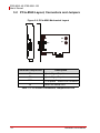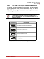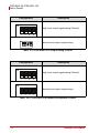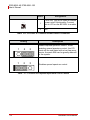
1
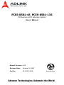
PCES-8581-4S PCES-8581-13S
PCI Express-to-PCI Extension System
User’s Manual
Manual Revision: 2.00
Revision Date:
October 19, 2007
Part No:
50-1S001-2000
Advance Technologies; Automate the World.
PCES-8581-4S PCES-8581-13S
User’s Manual
Revision History
Revision
Release Date
2.00
2007/10/19
ii
Description of Change(s)
Initial Release
PCES-8581-4S PCES-8581-13S
User’s Manual
Preface
Copyright 2007 ADLINK TECHNOLOGY INC.
This document contains proprietary information protected by copyright. All rights are reserved. No part of this manual may be reproduced by any mechanical, electronic, or other means in any form
without prior written permission of the manufacturer.
Disclaimer
The information in this document is subject to change without prior
notice in order to improve reliability, design, and function and does
not represent a commitment on the part of the manufacturer.
In no event will the manufacturer be liable for direct, indirect,
special, incidental, or consequential damages arising out of the
use or inability to use the product or documentation, even if
advised of the possibility of such damages.
Trademarks
PCI Express® is a registered trademark of the Peripheral
Component Interconnect Special Interest Group.
Product names mentioned herein are used for identification purposes only and may be trademarks and/or registered trademarks
of their respective companies.
Preface
iii
PCES-8581-4S PCES-8581-13S
User’s Manual
Using this Manual
Audience and Scope
The PCES-8581-4S PCES-8581-13S User’s Manual is intended
for hardware technicians and systems operators with knowledge
of installing, configuring and using PCI Express®-to-PCI extension
systems. This document is specifically intended to describe connecting ADLINK PCIS-8580-4S/PCIS-8505-13S PCI-to-PCIExtension Systems to a host computer or I/O devices for extended
functionality.
Manual Organization
This manual is organized as follows:
Preface: Presents important copyright notifications, disclaimers, trademarks, and associated information on the proper
understanding and usage of this document and its associated
product(s).
Chapter 1, Introduction: Introduces the PCES-8581-4S/13S
PCI Express®-to-PCI Extension System overview, its features,
applications, and package contents.
Chapter 2, Getting Started: Presents information on properly
installing PCES-8581-4S/13S equipment and cabling a PCI
Express® to PCI extension system.
Chapter 3, Hardware Information: Presents layout information, technical drawings, jumper settings and configuration.
Chapter 4, Troubleshooting: Provides basic information on
quickly addressing configuration/setup/installation problems
that may occur.
Important Safety Instructions: Presents safety instructions
all users must follow for the proper setup, installation and
usage of equipment and/or software.
Warranty Information: Presents important warranty information for users/manufacturers rights and responsibilities regarding ADLINK products and services.
iv
Preface
PCES-8581-4S PCES-8581-13S
User’s Manual
Conventions
Take note of the following conventions used throughout this
manual to make sure that users perform certain tasks and
instructions properly.
Additional information, aids, and tips that help users
perform tasks.
NOTE:
CAUTION:
Information to prevent minor physical injury, component
damage, data loss, and/or program corruption when
trying to complete a task.
WARNING:
Information to prevent serious physical injury,
component damage, data loss, and/or program
corruption when trying to complete a specific task.
Preface
v
PCES-8581-4S PCES-8581-13S
User’s Manual
Reference Documentation
The following list of documents may be used as reference materials to support installation, configuration and/or the operation of the
PCES-8581-4S/PCES-8581-13S. This list is prepared in alphabetical order (by vendor name, then by document title) for clarity.
Vendor(s)
Title
Rev.
ADLINK Technology, Inc.
ADLINK PCIS-8580-4S/PCIS-850513S User’s Manual
2.01
PCI-SIG
PCI Express® Base Specification
1.0a
PCI-SIG
PCI-to-PCI Bridge Architecture
Specification
1.2
PCI-SIG
PCI Local Bus Specification
3.0
vi
Preface
PCES-8581-4S PCES-8581-13S
User’s Manual
Getting Service
Contact us should you require any service or assistance.
ADLINK TECHNOLOGY INC. (HEADQUARTERS)
Web Site:
Sales & Service:
Telephone No.:
Fax No.:
Mailing Address:
http://www.adlinktech.com
[email protected]
+886-2-8226-5877
+886-2-8226-5717
9F No. 166 Jian Yi Road, Chungho City,
Taipei 235, Taiwan, ROC
ADLINK TECHNOLOGY AMERICA INC.
Sales & Service:
Toll-Free:
Fax No.:
Mailing Address:
[email protected]
+1-866-423-5465
+1-949-727-2099
8900 Research Drive, Irvine,
CA 92618, USA
ADLINK TECHNOLOGY CO. LTD. (BEIJING)
Sales & Service:
Telephone No.:
Fax No.:
Mailing Address:
[email protected]
+86-10-5885-8666
+86-10-5885-8625
Rm. 801, Power Creative E,
No. 1, B/D Shang Di East Rd.
Beijing, 100085 China
ADLINK TECHNOLOGY CO. LTD. (SHANGHAI)
Sales & Service:
Telephone No.:
Fax No.:
Mailing Address:
[email protected]
+86-21-6495-5210
+86-21-5450-0414
4F, Bldg. 39, No.333 Qinjiang Road,
Chao He Jing Hi Tech Park
Shanghai, 200233 China
ADLINK TECHNOLOGY CO. LTD. (SHENZHEN)
Sales & Service:
Telephone No.:
Fax No.:
Mailing Address:
Preface
[email protected]
+86-755-2643-4858
+86-755-2664-6353
2F, C Block, Bld. A1,
Cyber-Tech Zone, Gao Xin Ave. Sec 7,
High-Tech Industrial Park S.,
Shenzhen, 518057 China
vii
PCES-8581-4S PCES-8581-13S
User’s Manual
ADLINK TECHNOLOGY INC. (EUROPE)
Sales & Service:
Toll-Free:
Fax No.:
Mailing Address:
[email protected]
+49-211-495-5552
+49-211-495-5557
Nord Carree 3, 40477
Düsseldorf, Germany
ADLINK TECHNOLOGY INC. (INDIA)
Sales & Service:
Telephone No.:
Fax No.:
Mailing Address:
[email protected]
+91-80-6560-5817
+91-80-2244-3548
No. 1357, Ground Floor, "Anupama",
Aurobindo Marg JP Nagar (Ph-1)
Bangalore, Karnataka 560078, India
ADLINK TECHNOLOGY JAPAN CORP.
Sales & Service
Telephone No.
Fax No.
Mailing Address
[email protected]
+81-3-4455-3722
+81-3-5333-6040
Asahiseimei Hatagaya Bld. 1-1-2
Hatagaya Shibuya-ku, Tokyo, Japan
ADLINK TECHNOLOGY INC. (SOUTH KOREA)
Sales & Service:
Telephone No.:
Fax No.:
Mailing Address:
[email protected]
+82-2-2057-0565
+82-2-2057-0563
4F, Kostech Building, 262-2,
Yahgjae-Dong, Seocho-Gu,
Seoul, 137-130, South Korea
ADLINK TECHNOLOGY SINGAPORE PTE. LTD.
Sales & Service:
Telephone No.:
Fax No.:
Mailing Address:
viii
[email protected]
+65-6844-2261
+65-6844-2263
84 Genting Lane #07-02A,
Cityneon Design Center,
Singapore 349584
Preface
PCES-8581-4S PCES-8581-13S
User’s Manual
Table of Contents
PCES-8581-4S PCES-8581-13S............................................... i
Revision History...................................................................... ii
Preface .................................................................................... iii
Copyright 2007 ADLINK TECHNOLOGY INC. ...............iii
Disclaimer .......................................................................iii
Trademarks .....................................................................iii
Using this Manual ...........................................................iv
Conventions .................................................................... v
Reference Documentation ..............................................vi
Getting Service ..............................................................vii
Table of Contents................................................................... ix
List of Figures ........................................................................ xi
List of Tables........................................................................ xiii
1 Introduction ........................................................................ 1
1.1
Overview.............................................................................. 1
1.1.1 Controlling PCI with PCI Express®....................................... 1
1.2
Package Contents ............................................................... 3
1.3
Specifications....................................................................... 4
1.4
Features............................................................................... 5
1.5
Applications ......................................................................... 5
2 Getting Started ................................................................... 7
2.1
Installation Environment ...................................................... 7
2.2
Installing PCIe-8560 on a Host Computer ........................... 8
2.3
Installing PCI Peripheral Cards to an Extension Chassis .. 10
2.4
Cabling Host Computer to Extension Chassis................... 12
2.5
Power-ON/OFF Sequence................................................. 14
2.6
Remote Power-ON/OFF Functionality ............................... 15
2.7
LED Status......................................................................... 18
3 Hardware Information ...................................................... 19
3.1
Functional Block Diagram.................................................. 19
Table of Contents
ix
PCES-8581-4S PCES-8581-13S
User’s Manual
3.2
PCIe-8560 Layout, Connectors and Jumpers.................... 20
3.2.1 PCIe-8560 S1/S2 Signal Equalizer Adjustments ................ 21
3.3
PCI-8565 Layout, Connectors and Jumpers...................... 23
3.4
RK-8005 4-Slot Extension Chassis.................................... 25
3.4.1 RK-8005 Chassis Mechanical Drawing............................... 25
3.5
RK-8014 13-Slot Extension Chassis.................................. 27
3.5.1 RK-8014 Chassis Mechanical Drawing............................... 27
3.6
BP-8005 Layout, Connectors and Jumpers ....................... 29
3.7
BP-8014 Layout, Connectors and Jumpers ....................... 33
3.8
Extension Cable Options ................................................... 36
4 Troubleshooting (FAQ)..................................................... 37
Important Safety Instructions............................................... 41
Warranty Policy ..................................................................... 43
x
Table of Contents
PCES-8581-4S PCES-8581-13S
User’s Manual
List of Figures
Figure 2-1: PCIe-8560 to Host PC Installation Diagram .................... 9
Figure 2-2: PCI to Extension Chassis Installation Diagram ............. 11
Figure 2-3: Cabling 3 M Extension Cable to Host PC ...................... 12
Figure 2-4: Cabling 3 M Extension Cable to Extension Chassis...... 13
Figure 2-5: Host Computer connected to a PCI Extension System . 13
Figure 2-6: BP-8014 Remote Power-On/Off Diagram...................... 17
Figure 3-1: PCI Express Extension System Functional Block Diagram.......19
Figure 3-2: PCIe-8560 Mechanical Layout....................................... 20
Figure 3-3: PCI-8565 Mechanical Layout......................................... 23
Figure 3-4: RK-8005 Chassis Front and Back View......................... 25
Figure 3-5: RK-8005 Chassis Top View........................................... 26
Figure 3-6: RK-8005 Side View........................................................ 26
Figure 3-7: RK-8014 Front View ...................................................... 27
Figure 3-8: RK-8014 Back View....................................................... 27
Figure 3-9: RK-8014 Top View......................................................... 28
Figure 3-10: RK-8014 Side View........................................................ 28
Figure 3-11: BP-8005 Backplane Layout ........................................... 29
Figure 3-12: BP-8014 Backplane Layout ........................................... 33
Figure 3-13: Standard 3 M extension cable (ALC-PCEEXT-3) .......... 36
List of Figures
xi
PCES-8581-4S PCES-8581-13S
User’s Manual
This page intentionally left blank.
xii
List of Figures
PCES-8581-4S PCES-8581-13S
User’s Manual
List of Tables
Table
Table
Table
Table
Table
Table
Table
Table
Table
Table
Table
Table
Table
Table
Table
Table
Table
Table
Table
Table
Table
Table
Table
Table
Table
2-1:
2-2:
2-3:
2-4:
3-1:
3-2:
3-3:
3-4:
3-5:
3-6:
3-7:
3-8:
3-9:
3-10:
3-11:
3-12:
3-13:
3-14:
3-15:
3-16:
3-17:
3-18:
3-19:
3-20:
3-21:
List of Tables
PCIe-8560 to Host PC Chassis Installation Items ........... 9
PCI device to Host PC Chassis Installation Items ......... 11
Remote Power-ON/OFF Configuration.......................... 15
Remote Power-On/Off Diagram Description.................. 17
PCIe-8560 Connectors, Jumpers and LED ................... 20
PCIe-8560 Pin 1 and Pin 2 Equalizer Selection ............ 21
PCIe-8560 Pin 3 Output Swing Control ......................... 22
PCIe-8560 Pin 4 Output De-Emphasis Control ............. 22
PCI-8565 Connectors, Jumpers and LED ..................... 23
PCI-8565 JP1 Remote Power-ON/Off Connector.......... 24
PCI-8565 JP2 Spread Spectrum Clock Control............. 24
BP-8005 Connectors, Jumpers and LED....................... 30
BP-8005 CN1 LED Connector ....................................... 30
BP-8005 CN2 ATX Power Connector............................ 31
BP-8005 CN3 Fan Connector........................................ 31
BP-8005 CN4 ATX Power OK Status Connector .......... 31
BP-8005 JP1 LED Connector ........................................ 32
BP-8005 JP2 ATX Power Enable Connector................. 32
BP-8005 JP3 Fan Connector......................................... 32
BP-8014 Backplane Connectors and Jumpers.............. 34
BP-8014 JP2 ATX Power Enable Connector................. 34
BP-8014 JP2 ATX Power Enable Connector................. 34
BP-8014 FAN4, FAN5, and FAN6 +12 V Connector ..... 35
BP-8014 CN2 ATX Power Connector............................ 35
Optional Extension Cables ............................................ 36
xiii
PCES-8581-4S PCES-8581-13S
User’s Manual
This page intentionally left blank.
xiv
List of Tables
PCES-8581-4S PCES-8581-13S
User’s Manual
1
Introduction
This chapter introduces the PCES-8581-4S/13S PCI Express®to-PCI Extension System, presents a general overview and basic
applications, its package contents, specifications, and features.
1.1 Overview
Harnessing the bandwidth potential of PCI Express®, the PCES8581-4S and the PCES-8581-13S smart extension systems
enable computers with a PCI Express® slot to remotely manage
and control up to 13 PCI devices, using the high-speed PCI
Express® interface. These extension systems operate in 32-bit/33
MHz configuration and come with complete end-to-end hardware
and software transparency for the host system. Hardware devices
installed in the extension system behave and work as if they are
directly installed on the host system, requiring no additional drivers
or software installation.
The host system may be separated from the extension system at
up to seven meters using high-quality shielded twisted copper
cables. The robust and reliable PCI Express®-to-PCI extension
systems are suited for portable test and measurement applications with high-density I/O requirement and are ideal in hazardous
industrial control and automation environments.
1.1.1
Controlling PCI with PCI Express®
Based on PCI Express® technology, PCES-8581-4S and PCES8581-13S provide bus expansion capability through the highspeed differential signal interface. The PCES-8581-4S and PCES8581-13S use a signal equalizer and a PCI Express®-to-PCI
bridge to architecture a PCI Express® to PCI extension system.
With our PCES-8581-4S and PCES-8581-13S, user can use an
available PCI Express® slot to control an external PCI chassis.
Because the PCI Express® Bridge is a transparent bridge, there is
Introduction
1
PCES-8581-4S PCES-8581-13S
User’s Manual
no need to install any additional software when using PCI devices
in the external chassis.
The PCES-8581-13S and PCES-8581-4S implement a PCI
Express®-based control of PCI modules. The technology consists
of a PCIe-8560 card installed in the host computer, a shielded
cable, and the extension system. The PCIe-8560 comes in a PCI
Express® x1 footprint and communicates with the extension system's low-profile PCI-8565 via a twisted and shielded cable. The
PCI-8565 converts the PCI Express® interface into a PCI bridge
for additional PCI slots in the extension system.
The link between host PC and the external chassis is a PCI
Express® X1 link that represents a dual-simplex communications
channel consisting of two, low-voltage differentially driven signal
pairs. The signaling rate can reach up to 2.5 Gbps in each direction. Using the shielded and twisted cable, the maximum extension distance can be up to 7 M without decreasing the signal rate.
2
Introduction
PCES-8581-4S PCES-8581-13S
User’s Manual
1.2 Package Contents
PCES-8581-4S
X
PCIe-8560 (packaged separately)
X
RK-8005 wall-mount chassis, pre-installed with:
Z
PCI-8565 card
Z
5-slot backplane
Z
200 W AC power supply
X
3 m extension cable
X
AC power cord
X
Wall-mount kit for chassis
X
User's manual
PCES-8581-13S
X
PCIe-8560 (packaged separately)
X
RK-8014 wall-mount chassis, pre-installed with:
Z
PCI-8565
Z
14-slot backplane
Z
400 W AC power supply
X
3 m extension cable
X
AC power cord
X
Wall-mount kit for chassis
X
Remote power-on cable
X
User's manual
If any of the items on the contents list are missing or
damaged, contact your ADLINK dealer.
NOTE:
Introduction
3
PCES-8581-4S PCES-8581-13S
User’s Manual
1.3 Specifications
PCIe-8560 (on host computer)
X
Compliant with PCI Express® Base Specifications (Rev.
1.0a)
X
PCI Express® x1 link with 2.5 Gb/s data throughput
X
Maximum extended distance of up to seven meters
X
Low-profile footprint, 68.90 mm (H) x 86.65 mm (W)
X
Power requirement: 3.3 V, 210 mA (max)
PCI-8565 (on extension system)
X
Compliant with PCI-to-PCI Bridge Architecture Specifications (Rev. 1.2)
X
Supports 5 V and 3.3 V PCI bus
X
32-bit/33 MHz full data throughput
X
Maximum extended distance of seven meters
X
Low-profile footprint, 64.41 mm (H) x 119.91 mm (W)
X
Power requirement: +3.3 V, 720 mA
Operating and Storage Environments
4
X
Operating temperature: 0°C to 50°C
X
Storage temperature: -20°C to 80°C
X
Relative humidity: 10% to 90%, non-condensing
Introduction
PCES-8581-4S PCES-8581-13S
User’s Manual
1.4 Features
X
PCI Express® control of PCI cards
X
High-speed PCI Express® X1 interface
X
Compatible with 5 V and 3.3 V PCI bus
X
Supports 32-bit/33 MHz PCI interface
X
Provides four extended half-size PCI slots with built-in 200 W
power supply in a shoebox size chassis (PCES-8581-4S)
X
Provides 13 extended full-size PCI slots with built-in 400 W
power supply in 19" rack-mount chassis (PCES-8581-13S)
X
Extension lengths of 1 M, 3 M and 7 M
X
Complete hardware and software transparency
X
Compliant with PCI Express® Base Specification, Revision
1.0a
X
Compliant with PCI-to-PCI Bridge Architecture Specification,
Revision 1.2
X
Compliant with PCI Local Bus Specification, Revision 3.0
1.5 Applications
These extension systems are suitable for:
X
Electronics manufacturing testing
X
High-density I/O systems
X
Industrial automation and control
X
Military and aerospace
X
Testing systems for remote and/or harsh environments
X
Video capture
Introduction
5
PCES-8581-4S PCES-8581-13S
User’s Manual
This page intentionally left blank.
6
Introduction
PCES-8581-4S PCES-8581-13S
User’s Manual
2
Getting Started
This chapter describes the installation environment, installation
procedures, cabling the equipment, and instructions on poweringon/off the PCES-851-4S and PCES-851-13S PCI Express® to PCI
Extension Systems.
Diagrams and images of equipment mentioned are used
for reference only. Actual system appearance may vary.
NOTE:
2.1 Installation Environment
Whenever unpacking and preparing to install any equipment
described in this manual, please refer to the Important Safety
Instructions chapter of this manual.
Only install equipment in well lit areas on flat, sturdy surfaces with
access to basic tools such as flat and cross head screwdrivers.
The PCES-8581-4S and PCES-8581-13S contain several electrostatic sensitive components that can be easily damaged by static
electricity. For this reason, the card and chassis should be handled on a grounded anti-static mat and the operator should wear
an anti-static wristband during the unpacking and installation procedure.
Please also inspect the components for apparent damage.
Improper shipping and handling may cause damage to the components. Be sure there is no shipping and handling damage on the
components before continuing.
Do not apply power to any equipment if it has been
damaged.
CAUTION:
Getting Started
7
PCES-8581-4S PCES-8581-13S
User’s Manual
2.2 Installing PCIe-8560 on a Host Computer
1. Power-off your host computer.
2. Unscrew the housing of your host computer using a
(cross-head or flat-head) screwdriver. Open the housing.
3. Locate your PCI Express® extension card (PCIe-8560)
and remove it from its packaging. (Please wear antistatic gloves and use an anti-static surface when handling the card).
4. Install the PCIe-8560 in an available PCI Express® slot
in your host computer. Be sure to firmly attach the PCIe8560’s bracket to the backplane of the host PC.
5. Close the chassis and re-install its housing screws.
8
Getting Started
PCES-8581-4S PCES-8581-13S
User’s Manual
Figure 2-1: PCIe-8560 to Host PC Installation Diagram
B
B
C
C
A
A
Item
Description
A
Industrial PC or Desktop PC with X1 PCI Express® Slot
B
PCIe-8560 (PCI Express®-to-PCI extension host card)
C
PCI Express® Slot
Table 2-1: PCIe-8560 to Host PC Chassis Installation Items
Getting Started
9
PCES-8581-4S PCES-8581-13S
User’s Manual
2.3 Installing PCI Peripheral Cards to an Extension
Chassis
CAUTION:
The following instructions are for illustration purposes
when attempting to install additional PCI devices to your
extension chassis. Both RK-8005 and RK8014 extension
chassis are pre-installed with one PCI-8565 extension
card.
1. Locate your extension chassis (RK-8005 or RK-8014)
and plug-in the AC power cord but DO NOT power-on
the equipment.
2. Unscrew the four housing screws of the extension chassis using a (cross-head or flat-head) screwdriver. Open
the top cover of the chassis. You should see a row of
PCI slots (four slots for RK-8005 or 13 slots for RK-8014)
along the backplane.
3. Locate your PCI device and remove it from its packaging. (Please wear anti-static gloves and use an antistatic surface when handling the card).
4. Install your PCI device in an available PCI slot and be
sure to firmly attach it’s bracket to the backplane of the
extension chassis.
5. Close the extension chassis and re-install its housing
screws.
10
Getting Started
PCES-8581-4S PCES-8581-13S
User’s Manual
Figure 2-2: PCI to Extension Chassis Installation Diagram
C
B
D
A
Item
Description
A
Extension chassis (RK-8005)
B
Extension chassis housing screws
C
Additional PCI card/device
D
Pre-installed PCI-8565
Table 2-2: PCI device to Host PC Chassis Installation Items
Getting Started
11
PCES-8581-4S PCES-8581-13S
User’s Manual
2.4 Cabling Host Computer to Extension Chassis
Now that you have successfully installed the PCIe-8560 into the
Host computer (or installed an additional PCI device in the extension chassis), you may connect the Host Computer and Extension
Chassis with an extension cable.
CAUTION:
Do not remove the extension cable after the system is
powered on. It may cause system errors or data loss. If
the cable is unplugged improperly, reconnect it and
reboot the host PC and extension chassis.
1. Locate your 3 M extension cable.
2. Connect the 3 M extension cable to the PCI Express®
serial link connector (PCIe-8560) of your host PC.
3. Firmly attach the 3 M extension cable by tightening its
retention screws.
Figure 2-3: Cabling 3 M Extension Cable to Host PC
12
Getting Started
PCES-8581-4S PCES-8581-13S
User’s Manual
4. Connect the other end of the 3 M extension cable to the
PCI-8565 serial link connector of the extension chassis
(RK-8005 or RK-8014).
Figure 2-4: Cabling 3 M Extension Cable to Extension Chassis
Figure 2-5: Host Computer connected to a PCI Extension System
Getting Started
13
PCES-8581-4S PCES-8581-13S
User’s Manual
2.5 Power-ON/OFF Sequence
To power-on the PCI express® extension system, follow these steps:
1. Check that the 3 M extension cable is properly connected to the host PC and extension chassis.
2. Power-on the extension chassis first.
3. Power-on the host PC.
CAUTION:
DO NOT remove the cable after the system and
extension chassis are powered on. Disconnecting the
cable while the system is running may cause
unpredictable system errors and/or system crash.
As the PCI Express®-to-PCI extension system is a standard PCIeto-PCI bridge interface, the BIOS will identify each device behind
the PCI bridge and assign resource to each one during start up.
Thus users have to power-on the remote chassis first in order to
get appropriate resources from the BIOS.
To power-off the PCI Express® extension system, follow these steps:
1. Power-off the host PC.
2. Power-off the extension chassis.
CAUTION:
14
DO NOT power-off the extension chassis until the host
PC is powered off. If the extension chassis is powered off
while the host PC is on, the host PC may hang or crash.
Getting Started
PCES-8581-4S PCES-8581-13S
User’s Manual
2.6 Remote Power-ON/OFF Functionality
Optional functionality of the PCI express® extension system
includes remote power-on/off via the ADLINK BP-8014 backplane.
Once the BP-8014 is properly connected, configured, and
enabled, users may remotely power-on/off the extension chassis
via a host PC.
The following table lists the connectors that enable remote poweron/off functionality.
Part Number
Connector/
Jumper
Function
PCI-8565
JP1
A signal is sent from JP1 on PCI-8565 which
enables the RK-8014 to power-on when the
host PC is powered on.
BP-8014
JP2
ATX power enabling connector for BP-8014
Table 2-3: Remote Power-ON/OFF Configuration
Please refer to sections 3.3, 3.4, 3.5, 3.6 and 3.7 for
detailed layout, connectors and jumpers.
NOTE:
Getting Started
15
PCES-8581-4S PCES-8581-13S
User’s Manual
To enable remote power-on/off functionality, follow these steps:
1. Unscrew the four housing screws of the extension chassis (RK-8014) using a (cross-head or flat-head) screwdriver. Open the top cover of the chassis.
2. Disconnect the power-on button of the RK-8014 chassis
panel.
3. Locate the JP2 connector on the BP-8014 as well as the
JP1 of the PCI-8565.
BP-8014 JP2
Connector
PCI-8565 JP1
Connector
16
Getting Started
PCES-8581-4S PCES-8581-13S
User’s Manual
4. Using a controller cable, connect the JP1 of the PCI8565 and JP2 of the BP-8014.
Figure 2-6: BP-8014 Remote Power-On/Off Diagram
Item
A
Description
PCI-8565
B
BP-8014
C
JP1 on PCI-8565. JP2 is used for controlling
remote chassis power.
D
JP2 on BP-8014 is used to control the ATX
power of RK-8014.
E
Remote power-on/off control cable.
Table 2-4: Remote Power-On/Off Diagram Description
Getting Started
17
PCES-8581-4S PCES-8581-13S
User’s Manual
2.7 LED Status
The LEDs on the front panel of the PCIe-8560 and PCI-8565 give
power status information. The LEDs light up only when the following conditions are met:
18
X
The extension cable between the PCIe-8560 (Host PC) and
PCI-8565 (Extension Chassis) is properly connected.
X
The extension chassis is powered on.
X
The host PC is entering its Power-On Self Test (POST).
Getting Started
PCES-8581-4S PCES-8581-13S
User’s Manual
3
Hardware Information
3.1 Functional Block Diagram
Figure 3-1: PCI Express Extension System Functional Block Diagram
Remote Chassis
RK-8005 / RK-8014
Host PC
Signal
Equalizer
Hardware Information
External Cable
PCI Slot
PCI Express-toPCI Bridge
32-Bit/33MHz PCI Bus
X1 PCI Express
PCI Slot
PCI-8565
PCIe-8560
PCI Slot
19
PCES-8581-4S PCES-8581-13S
User’s Manual
3.2 PCIe-8560 Layout, Connectors and Jumpers
Figure 3-2: PCIe-8560 Mechanical Layout
D1
CN1
Connector/Jumper/LED
S2
S1
Description
S1
Adjusts Signal Equalizer
S2
Adjusts Signal Equalizer
CN1
D1
PCI Express® Serial Link Connector
Serial Link Status LED
Table 3-1: PCIe-8560 Connectors, Jumpers and LED
20
Hardware Information
PCES-8581-4S PCES-8581-13S
User’s Manual
3.2.1
PCIe-8560 S1/S2 Signal Equalizer Adjustments
PCIe-8560 provides equalization, amplification and de-emphasis
circuits to optimize signal integrity performance. With this design,
PCIe-8560 allows signal transmission over long distances and
reduces signal distortion.
The following adjustment should be applied to both S1
and S2 simultaneously. The S1 transmits signals and S2
is receives signals.
NOTE:
Configuration
Description
ON
Strongest equalizer levels (default)
1
2
3
4
1
2
3
4
ON
Moderate equalizer level
ON
Weakest equalizer level
1
2
3
4
1
2
3
4
ON
No equalizer
Table 3-2: PCIe-8560 Pin 1 and Pin 2 Equalizer Selection
Hardware Information
21
PCES-8581-4S PCES-8581-13S
User’s Manual
Configuration
Description
ON
High level output signal swing (Default)
1
2
3
4
Normal level output signal swing
ON
1
2
3
4
Table 3-3: PCIe-8560 Pin 3 Output Swing Control
Configuration
Description
ON
High level output signal swing (Default)
1
2
3
4
ON
Normal level output signal swing
1
2
3
4
Table 3-4: PCIe-8560 Pin 4 Output De-Emphasis Control
22
Hardware Information
PCES-8581-4S PCES-8581-13S
User’s Manual
3.3 PCI-8565 Layout, Connectors and Jumpers
Figure 3-3: PCI-8565 Mechanical Layout
JP2
JP1
D1
CN1
Connector/Jumper/LED
Description
JP1
ATX power enabling connector. This connector
is used for remote power-on control.
JP2
Spread spectrum clock control
CN1
PCI Express® serial link connector
D1
Serial Link Status LED
Table 3-5: PCI-8565 Connectors, Jumpers and LED
Hardware Information
23
PCES-8581-4S PCES-8581-13S
User’s Manual
2 3
JP1
Pin #
Assignment
1
PWR-ON. This pin is used for remote
power-on/off functionality. Connect
this to JP2 on the BP-8014 to enable
it.
2
N/C
Table 3-6: PCI-8565 JP1 Remote Power-ON/Off Connector
Setting
Description
1
2
3
1
2
3
Enables spread spectrum control. When
enabling spread spectrum control, the PCI
clock will be modulated with a low frequency
carrier, the peak EMI can be greatly reduced
in the system.
Disables spread spectrum control.
Table 3-7: PCI-8565 JP2 Spread Spectrum Clock Control
24
Hardware Information
PCES-8581-4S PCES-8581-13S
User’s Manual
3.4 RK-8005 4-Slot Extension Chassis
RK-8005 is a robust industrial chassis for accommodating the BP8005 backplane. The RK-8005 is a small, compact chassis
(122mm X 195mm X 260mm) with a built-in 200W universal AC
power supply. The RK-8005 is provided with a wall-mount kit so
you can place it in many different environments.
Only half-size PCI cards are suitable for the RK-8005.
NOTE:
3.4.1
RK-8005 Chassis Mechanical Drawing
Figure 3-4: RK-8005 Chassis Front and Back View
Hardware Information
25
PCES-8581-4S PCES-8581-13S
User’s Manual
Figure 3-5: RK-8005 Chassis Top View
Figure 3-6: RK-8005 Side View
26
Hardware Information
PCES-8581-4S PCES-8581-13S
User’s Manual
3.5 RK-8014 13-Slot Extension Chassis
RK-8014 is a robust industrial chassis for accommodating the BP8014 backplane. The RK-8014 is a 177 mm X 481.1 mm X 438.5
mm chassis with a built-in 200W universal AC power supply.
3.5.1
RK-8014 Chassis Mechanical Drawing
Figure 3-7: RK-8014 Front View
101.50mm [4.00in]
177.00mm [6.97in]
481.10mm [18.96in]
Figure 3-8: RK-8014 Back View
429.30mm [16.91in]
Hardware Information
27
PCES-8581-4S PCES-8581-13S
User’s Manual
120.20mm [4.74in]
438.50mm [17.28in]
Figure 3-9: RK-8014 Top View
448.50mm [17.67in]
Figure 3-10: RK-8014 Side View
28
Hardware Information
PCES-8581-4S PCES-8581-13S
User’s Manual
3.6 BP-8005 Layout, Connectors and Jumpers
The BP-8005 backplane provides 1 system slot and 4 available
PCI peripheral slots. These PCI slots are for 32-bit and 33MHz
PCI devices.
The system slot is occupied by a pre-installed PCI-8565,
please DO NOT install a CPU controller in this slot.
CAUTION:
Figure 3-11: BP-8005 Backplane Layout
PCI4
PCI3
PCI2
PCI1
SYSTEM
CN2
JP1 JP3
CN3
CN4 CN1 JP2
Top View
Hardware Information
Soldered Side
29
PCES-8581-4S PCES-8581-13S
User’s Manual
Connector/Jumper/LED
Description
CN1
LED connector
CN2
ATX power connector
CN3
Fan connector
CN4
ATX power OK status connector
JP1
LED connector
JP2
ATX power enabler
JP3
Fan connector
System
PCI1 to PCI4
System slot for extension card. This slot is modified for bus extension purposes and does not
support general signal board controllers.
Peripheral PCI Slot
Table 3-8: BP-8005 Connectors, Jumpers and LED
DO NOT plug CPU cards in the system slot.
CAUTION:
Pin #
Assignment
1
Ground
2
+5 V Output
CN1
Table 3-9: BP-8005 CN1 LED Connector
30
Hardware Information
PCES-8581-4S PCES-8581-13S
User’s Manual
Pin #
Assignment
Pin #
Assignment
CN2
1
+3.3 V
11
+3.3 V
2
+3.3 V
12
-12 V
3
Ground
13
Ground
4
+5 V
14
PS-ON
5
Ground
15
Ground
6
+5 V
16
Ground
7
Ground
17
Ground
8
PW-OK
18
-5 V
9
5 VSB
19
+5 V
10
+12 V
20
+5 V
Table 3-10: BP-8005 CN2 ATX Power Connector
Pin #
CN3
Assignment
1
N/C
2
+12 V
3
Ground
Table 3-11: BP-8005 CN3 Fan Connector
Pin #
Assignment
1
Ground
2
PW-OK. ATX Power Status
Table 3-12: BP-8005 CN4 ATX Power OK Status Connector
Hardware Information
31
PCES-8581-4S PCES-8581-13S
User’s Manual
Pin #
Assignment
1
Ground
2
LED Power, +5 V
JP1
Table 3-13: BP-8005 JP1 LED Connector
Pin #
Assignment
1
Ground
2
PWR-ON, ATX Power Enable
JP2
Table 3-14: BP-8005 JP2 ATX Power Enable Connector
Pin #
Assignment
1
Ground
2
+12 V
JP3
Table 3-15: BP-8005 JP3 Fan Connector
32
Hardware Information
PCES-8581-4S PCES-8581-13S
User’s Manual
3.7 BP-8014 Layout, Connectors and Jumpers
The BP-8014 backplane provides 1 system slot and 13 available
PCI peripheral slots. The system is occupied by a pre-installed
PCI-8565 PCI extension card. The remaining PCI slots are available for 5 V or universal PCI peripheral cards.
Figure 3-12: BP-8014 Backplane Layout
SYSTEM Slot
CN2
JP1
JP4
JP5
JP3
FAN5
JP6
Hardware Information
JP2
FAN4
FAN6
33
PCES-8581-4S PCES-8581-13S
User’s Manual
Connector/Jumper
Description
JP2
ATX power enabling connector
JP6
ATX power OK status connector
JP7
LED connector
FAN4
Fan connector for +12 V fan
FAN5
Fan connector for +12 V fan
FAN6
Fan connector for +12 V fan
CN2
ATX power connector
Table 3-16: BP-8014 Backplane Connectors and Jumpers
Pin #
1
2
JP2
Assignment
1
PWR-ON
2
If JP3 2-3 connected, this pin is
Ground (Default).
For PCES-8580-13S extension system, user should not change the setting of JP3.
Table 3-17: BP-8014 JP2 ATX Power Enable Connector
Pin #
1
2
JP6
Assignment
1
PWR-OK
2
5 Vsb, +5 V standby power
Table 3-18: BP-8014 JP2 ATX Power Enable Connector
34
Hardware Information
PCES-8581-4S PCES-8581-13S
User’s Manual
Pin #
3 21
Assignment
1
N/C
2
+12 V
3
Ground
Table 3-19: BP-8014 FAN4, FAN5, and FAN6 +12 V Connector
Pin #
Assignment
Pin #
Assignment
CN2
1
+3.3 V
11
+3.3 V
2
+3.3 V
12
-12 V
3
Ground
13
Ground
4
+5 V
14
PS-ON
5
Ground
15
Ground
6
+5 V
16
Ground
7
Ground
17
Ground
8
PW-OK
18
-5 V
9
5 VSB
19
+5 V
10
+12 V
20
+5 V
Table 3-20: BP-8014 CN2 ATX Power Connector
Hardware Information
35
PCES-8581-4S PCES-8581-13S
User’s Manual
3.8 Extension Cable Options
The PCI Express®-to-PCI extension system (PCES-8581-13S and
PCES-8581-4S) is available with three different cables in length.
These cables are designed to transfer high speed signals and
have high immunity from electromagnetic interference.
Figure 3-13: Standard 3 M extension cable (ALC-PCEEXT-3)
Part Number
Description
ACL-EXPRESS-1
1 M, PCI Express®-to-PCI extension cable
ACL-EXPRESS-3
3 M, PCI Express®-to-PCI extension cable
ACL-EXPRESS-7
7 M, PCI Express®-to-PCI extension cable
Table 3-21: Optional Extension Cables
36
Hardware Information
PCES-8581-4S PCES-8581-13S
User’s Manual
4
Troubleshooting (FAQ)
This chapter describes frequently asked questions that may guide
the user to solve minors problem they may encounter.
This Troubleshooting (FAQ) applies to:
X
PCI Express®-to-PCI Extension System: including PCES8581-13S and PCES-8581-4S.
X
PCI Express-to-PXI Extension Kit: including PCIe-8560 and
PXI-8565.
In the following description, the products will be renamed as "PCI
Express® Bus Extension Products".
Question: What is the maximum extension length of PCI
Express® Bus Extension Products?
Answer: The maximum extension length is 7m. ADLINK offers
three different cables in length for customer's applications, 1
M, 3 M and 7 M.
Question: When using ADLINK PCI Express® Bus Extension
Products, is there any additional driver or software required
to install?
Answer: ADLINK PCI Express® Bus Extension Products are
designed to be standard PCI Express®-to-PCI bridges. It is
not necessary to install additional drivers or software for
support.
Question: How many extension chassis can I connect to a host
PC by using ADLINK PCI Express® Bus Extension Products?
Answer: Due to the point-to-point architecture of PCI Express®,
only one ADLINK PCI Express® Bus Extension Product can
Troubleshooting (FAQ)
37
PCES-8581-4S PCES-8581-13S
User’s Manual
be supported by one chassis. However, users can select
multiple extension chassis for different purposes. For example, a 4-slot extension chassis provides small and compact
form factor while an 18-slot extension chassis provides
more PCI slots. Theoretically, PCI specification allows up to
255 PCI bus segments. ADLINK PCI Express® Bus Extension Products do not limit the bus segment number. The
maximum PCI bus segments may limited by your BIOS or
operating system.
Question: Is there any compatibility problems with the ADLINK
PCI Express®-to-PXI extension kit?
Answer: ADLINK PCI Express® Bus Extension Products are
designed as standard PCI Express®-to-PCI Bridge. During
PC boot up, your PC BIOS will search devices and assign
resources such as, I/O, memory space and IRQ number, to
each device according to its algorithm. Although PCI specification allows up to 255 bus segments in a PC system, the
BIOS may not assign the correct and/or proper resource to
each device in some complex PCI systems.
Because the PCI Express® specification was released in
2002, most hardware and circuit board designers as of yet
do not offer multiple PCI-to-PCI bridges. Most BIOS work
for simple applications but may not work for multiple PCI
bus segments and a variety of resource requests. We suggest customers choose PC equipment with Intel 945, 965 or
later chipsets to adjust for these issues.
Question: When I encounter compatibility problems, what should
I do?
Answer: Because most compatibility problems come from PCI
resource assignments, customers should consult their PC
vendors or BIOS vendors for help. Updating to the most current BIOS version may also resolve PCI resources problems.
38
Troubleshooting (FAQ)
PCES-8581-4S PCES-8581-13S
User’s Manual
The following list are some indications that may help customers to
deal with compatibility issues:
1. Disable the onboard device functions of your host PC to
release IO resources.
2. Remove PCI devices plugged/installed in your host PC.
3. Connect an extension chassis which is single bus segment to the host PC. Plug a PCI device to an extension
chassis one by one and boot each in sequence to check
if your host PC can accommodate the PCI device or not.
4. You may try to plug the PCI Express® extension host
card to a different PCI Express® slot.
Troubleshooting (FAQ)
39
PCES-8581-4S PCES-8581-13S
User’s Manual
This page intentionally left blank.
40
Troubleshooting (FAQ)
PCES-8581-4S PCES-8581-13S
User’s Manual
Important Safety Instructions
For user safety, please read and follow all instructions,
WARNINGS, CAUTIONS, and NOTES marked in this manual
and on the associated equipment before handling/operating the
equipment.
X
Read these safety instructions carefully.
X
Keep this user’s manual for future reference.
X
Read the specifications section of this manual for detailed
information on the operating environment of this equipment.
X
When installing/mounting or uninstalling/removing
equipment:
Z
X
Turn off power and unplug any power cords/cables.
To avoid electrical shock and/or damage to equipment:
Z
Keep equipment away from water or liquid sources;
Z
Keep equipment away from high heat or high humidity;
Z
Keep equipment properly ventilated (do not block or
cover ventilation openings);
Z
Make sure to use recommended voltage and power
source settings;
Z
Always install and operate equipment near an easily
accessible electrical socket-outlet;
Z
Secure the power cord (do not place any object on/over
the power cord);
Z
Only install/attach and operate equipment on stable
surfaces and/or recommended mountings; and,
Z
If the equipment will not be used for long periods of time,
turn off and unplug the equipment from its power source.
X
Never attempt to fix the equipment. Equipment should only
be serviced by qualified personnel.
X
A Lithium-type battery may be provided for uninterrupted,
backup or emergency power.
CAUTION:
Risk of explosion if battery is replaced by an incorrect type.
Dispose of used batteries according to the instructions.
Important Safety Instructions
41
PCES-8581-4S PCES-8581-13S
User’s Manual
X
42
Equipment must be serviced by authorized technicians
when:
Z
The power cord or plug is damaged;
Z
Liquid has penetrated the equipment;
Z
It has been exposed to high humidity/moisture;
Z
It is not functioning or does not function according to the
user’s manual;
Z
It has been dropped and/or damaged; and/or,
Z
It has an obvious sign of breakage.
Important Safety Instructions
PCES-8581-4S PCES-8581-13S
User’s Manual
Warranty Policy
Thank you for choosing ADLINK. To understand your rights and
enjoy all the after-sales services we offer, please read the following carefully.
1. Before using ADLINK’s products please read the user
manual and follow the instructions exactly. When sending in damaged products for repair, please attach an
RMA application form which can be downloaded from:
http://rma.adlinktech.com/policy/
2. All ADLINK products come with a limited two-year warranty, one year for products bought in China:
X
The warranty period starts on the day the product is shipped
from ADLINK’s factory.
X
Peripherals and third-party products not manufactured by
ADLINK will be covered by the original manufacturers' warranty.
X
For products containing storage devices (hard drives, flash
cards, etc.), please back up your data before sending them
for repair. ADLINK is not responsible for any loss of data.
X
Please ensure the use of properly licensed software with
our systems. ADLINK does not condone the use of pirated
software and will not service systems using such software.
ADLINK will not be held legally responsible for products
shipped with unlicensed software installed by the user.
X
For general repairs, please do not include peripheral accessories. If peripherals need to be included, be certain to
specify which items you sent on the RMA Request & Confirmation Form. ADLINK is not responsible for items not listed
on the RMA Request & Confirmation Form.
Warranty Policy
43
PCES-8581-4S PCES-8581-13S
User’s Manual
3. Repair service is not covered by ADLINK's two-year
guarantee in the following situations:
X
Damage caused by not following instructions in the User's
Manual.
X
Damage caused by carelessness on the user's part during
product transportation.
X
Damage caused by fire, earthquakes, floods, lightening,
pollution, other acts of God, and/or incorrect usage of voltage transformers.
X
Damage caused by inappropriate storage environments
such as high temperatures, high humidity, or volatile chemicals.
X
Damage caused by leakage of battery fluid during or after
change of batteries by customer/user.
X
Damage from improper repair by unauthorized technicians.
X
Products with altered and/or damaged serial numbers are
not entitled to our service.
X
This warranty is not transferable or extendable.
X
Other categories not protected under our warranty.
4. Customers are responsible for all fees necessary to
transport damaged products to ADLINK.
5. To ensure the speed and quality of product repair,
please download an RMA application form from our
company website: http://rma.adlinktech.com/policy/
Products with attached RMA forms receive priority.
For further questions, please e-mail our FAE staff:
[email protected].
44
Warranty Policy