1
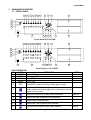
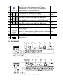
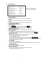
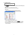
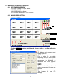
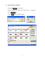
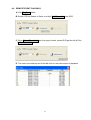
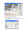
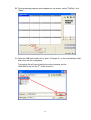
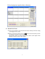
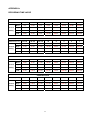
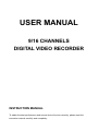
USER MANUAL
9/16 CHANNELS
DIGITAL VIDEO RECORDER
INSTRUCTION MANUAL
To obtain the best performance and ensure device function correctly, please read this
instruction manual carefully and completely.
INSTRUCTION MANUAL
To obtain the best performance and ensure device function correctly, please read this instruction manual
carefully and completely.
FCC Compliance
USER-INSTALLER CAUTION: YOUR AUTHORITY TO OPERATE THIS FCC VERIFIED EQUIPMENT
COULD BE VOIDED IF YOU MAKE CHANGES OR MODIFICATIONS NOT EXPRESSLY APPROVED BY
THE PARTY RESPONSIBLE FOR COMPLIANCE TO PART 15 OF THE FCC RULES.
NOTE: THIS EQUIPMENT HAS BEEN TESTED AND FOUND TO COMPLY WITH THE LIMITS FOR A
CLASS A DIGITAL DEVICE, PURSUANT TO PART 15 OF THE FCC RULES. THESE LIMITS ARE
DESIGNED TO PROVIDE REASONABLE PROTECTION AGAINST HARMFUL INTERFERENCE WHEN
THE EQUIPMENT IS OPERATED IN A COMMERCIAL ENVIRONMENT. THIS EQUIPMENT GENERATES,
USES, AND CAN RADIATE RADIO FREQUENCY ENERGY AND IF NOT INSTALLED AND USED IN
ACCORDANCE WITH THE INSTRUCTION MANUAL, MAY CAUSE HARMFUL INTERFERENCE TO
RADIO COMMUNICATIONS.
OPERATION OF THIS EQUIPMENT IN A RESIDENTIAL AREA IS LIKELY TO CAUSE HARMFUL
INTERFERENCE IN WHICH CASE THE USER WILL BE REQUIRED TO CORRECT THE INTERFERENCE
AT HIS OWN EXPENSE.
THIS CLASS A DIGITAL APPARATUS MEETS ALL REQUIREMENTS OF THE CANADIAN
INTERFERENCE-CAUSING EQUIPMENT REGULATIONS.
WARNINGS, CAUTIONS & COPYRIGHT
WARINGS
TO REDUCE THE RISK OF FIRE OR ELECTRIC SHOCK, DO NOT EXPOSE THIS PRODUCT TO RAIN OR
MISTURE.
DO NOT INSERT ANY METALLIC OBJECT THROUGH VENTILATION GRILLS.
CAUTION
CAUTION
RISK OF ELECTRIC SHOCK
DO NOT OPEN
CAUTION: TO REDUCE THE RISK OF ELECTRIC SHOCK.
DO NOT REMOVE COVER (OR BACK).
NO USER-SERVICEABLE PARTS INSIDE.
REFER SERVICING TO QUALIFIED SERVICE PERSONNEL.
Explanation of Graphical Symbols
The lightning flash with arrowhead symbol, within an equilateral triangle, is intended to alert
the user to the presence of insinuated "dangerous voltage" within the products enclosure
that may be of sufficient magnitude to constitute a risk of electric shock to persons.
The exclamation point within an equilateral rhombus is intended to alert the user to the
presence of important operating and maintenance (servicing) instruction in the literature
accompanying the product.
USERS OF THE SYSTEM ARE RESPONSIBLE FOR CHECKING AND COMPLYING WITH ALL FEDERAL,
STATE, AND LOCAL LAWS AND STATUTES COIPCERNING THE MONITORING AND RECORDING OF
VIDEO AND AUDIO SIGNALS. ULTRAK SHALL NOT BE HELD RESPONSIBLE FOR THE USE OF THIS
SYSTEM IN VIOLATION OF CURRENT LAWS AND STATUTES.
COPYRIGHT
THE TRADEMARKS MENTIONED IN THE MANUAL ARE LEGALLY REGISTERED TO THEIR
RESPECTIVE COMPANIES.
1
TABLE OF CONTENTS
WARNINGS, CAUTIONS & COPYRIGHT..............................................................
TABLE OF CONTENTS..........................................................................................
1
INTRODUCTION..............................................................................................
1.1 FEATURE................................................................................................
1.2 SPECIFICATION.....................................................................................
2 HARDWARE OVERVIEW................................................................................
2.1 FRONT PANEL........................................................................................
2.2 BACK PANEL..........................................................................................
3 SYSTEM CONNECTION.................................................................................
3.1 CAMERA & MONITOR LOOPING...........................................................
3.2 EXTERAL ALARM...................................................................................
3.3 RS-232/485 CONTROLLER....................................................................
3.4 PTZ (PAN, TILT AND ZOOM) CAMERA & JOYSTICK CONTROLLER..
3.5 NETWORK..............................................................................................
4 SYSTEM SETUP.............................................................................................
4.1 SETUP MENU DIAGRAM.......................................................................
4.2 LIVE VIEWING.........................................................................................
4.3 SYSTEM SETUP.....................................................................................
4.4 CAMERA SETUP.....................................................................................
4.5 MOTION SETUP......................................................................................
4.6 RECORD SETUP.....................................................................................
4.7 ALARM SETUP........................................................................................
4.8 EVENT LIST.............................................................................................
4.9 HDD MANAGEMENT..............................................................................
4.10 NETWORK SETUP..................................................................................
4.11 FIRMWARE UPDATE..............................................................................
4.12 CDRW BACKUP......................................................................................
4.13 LOAD DEFAULT......................................................................................
5 DVR PLAYBACK & USB BACKUP...................................................................
5.1 PLAY TIME SEARCH..............................................................................
5.2 EVENT LIST SEARCH............................................................................
5.3 USB BACKUP..........................................................................................
6 NETWORK & BACKUP PLAYBACK................................................................
6.1 SYSTEM REQUIREMENT.......................................................................
6.2 MAIN SCREEN........................................................................................
6.3 LINK TO DVR & LIVE VIDEO..................................................................
6.4 REMOTE EVENT PLAYBACK.................................................................
6.5 CDRW BACKUP PLAYBACK..................................................................
6.6 USB & LOCAL BACKUP FILE PLAYBACK..............................................
6.7 BACKUP FILE TO AVI.............................................................................
6.8 LOCAL BACKUP......................................................................................
APPENDIX A: RECORDING TIME LAPSE............................................................
V1.01
1
2
3
3
3
4
4
5
6
6
7
9
10
11
12
12
13
14
15
15
16
18
19
20
21
22
23
23
24
24
24
24
25
25
25
26
26
27
28
30
31
32
31/OCT/2005
11633RFMK01
2
1
INTRODUCTION
1.1 FEATURE
z
z
z
z
z
EASY OPERATION, SETTING CAN BE EASILY MODIFIED ON SCREEN DISPLAY.
MULTI-SPEED RECORDING SELECTION ON NORMAL OR ALARM RECORDING
MODE UP TO 60/50 (NTSC / PAL) FIELDS.
SHUTTLE FOR FAST/SLOW VIEWING, JOG DIAL FOR FIELD BY FIELD PLAYBACK.
BUILD-IN RS-232 AND RS-485 PORT ARE READY FOR SUB-CONTROL
PANELS ADD ON IN THE FUTURE.
CDRW, USB & VGA FUNCTION.
1.2 SPECIFICATION
IMAGE SYSTEM
RESOLUTION-LIVE
RESOLUTION-PLAYBACK
VIDEO INPUT
VIDEO LOOPING
VIDEO OUTPUT
SPOT OUTPUT
AUDIO INPUT
AUDIO OUTPUT
STORAGE MEDIA
IMAGE FORMAT
RECORDING RATE
RECORDING MODE
PLAYBACK SPEED
TITLE
OSD & SETUP
ALARM INPUT
RELAY OUTPUT
RS-232 & RS-485 PORT
PTZ CONTROL
ETHERNET
IR REMOTE CONTROL
BACKUP
VGA OUTPUT
PASSWORD CONTROL
KEY LOCK
POWER INPUT
DIMENSIONS MM
RACK MOUNTABLE
NTSC
PAL
720×480
720×576
720×240
720×288
BNC × 9 / BNC x16
BNC × 9 / BNC x16
BNC × 1
BNC × 1
RCA × 1
RCA × 1
MAX 2 IDE HARD DISKS ( ONE REMOVABLE )
M-JPEG
UP TO 60 FIELDS/SEC
UP TO 50 FIELDS/SEC
MANUAL / ALARM / SCHEDULE
FAST FORWARD ×2 ×4 ×6 ×8 ×16 x32
FAST BACKWARD ×2 ×4 ×6 ×8 ×16
FIELD BY FIELD PLAYBACK
6 CHARACTERS FOR EACH CAMERA
TITLE / TIME / DATE / SETUP MENU
×9 / x16 N.O. OR N.C. PROGRAMMABLE
N.O. OR N.C. PROGRAMMABLE CONTACT ×1
YES
YES
YES
YES
USB & CDRW
OPTION
ONE FOR SYSTEM, ONE FOR HDD FORMAT
YES
AC 100-240V INPUT ( 47-63 HZ )
430(W) × 91(H) × 380(D)
EIA 19” 2U STANDARD MOUNTING RACK
3
11633RFMK01
2
HARDWARE OVERVIEW
2.1 FRONT PANEL
5
6
7
8
9 10 11 12
REC
Rew
Search
REW
Field
Rew
STOP
Field
Fwd
PLAY
F.Fwd
Search
1
2
3
4
5
6
7
8
15
16
23
17
1
2
POWER
3
H.D.D
REC
PLAY
4
MENU
9
AUTO
SEL
ENTER
COPY
24
14 19 20 21
13
18
22
Front Panel of 9-ch DVR
5
6
7
8
9 10 11 12
REC
Rew
Search
REW
Field
Rew
STOP
Field
Fwd
PLAY
F.Fwd
Search
6
7
8
14
15
16
15
16
23
17
1
2
POWER
3
H.D.D
REC
PLAY
4
1
2
3
4
5
9
10
11
12
13
MENU
AUTO
SEL
ENTER
COPY
13
24
14 19 20 21
18
22
Front Panel of 16-ch DVR
DVR OPERATION
NO.
LABEL
1
POWER Power LED
2
Recording LED
REC
3
Play LED
PLAY
4
H.D.D LED
H.D.D
5
REC
OPERATION
PTZ
Press REC to start recording. Press again to stop.
7
From ×2,×4,×6,X8 to the highest ×16 speed fast rewind
mode, speed and rewind sign will be indicated in top left
corner on the screen.
Press the Rew button to play video backward.
Zoom out
8
Press Field Rew to pause video backward
9
Press Stop to stop playback
10
Press Field Fwd to pause video forward
11
Press the Play button to play video forward.
6
4
Zoom in
Press F. Fwd to play video forward at high speed.
Press the button again the speed will be change
circulative from ×2,×4,×6,x8,x16 to the highest ×32.
12
13
1-9 / 1-16 Press the button to display full screen.
Move downward or decrease the number.
Down
Select full/quad formats at 9/16-ch DVR model.
Move leftward or decrease the number
Left
Select 8/13 camera formats at 9/16-ch DVR model.
Move upward or increase the number.
Up
Select quad/9 camera formats at 9/16-ch DVR model.
Move rightward or increase the number
Right
Select 9/16 camera formats at 9/16-ch DVR model.
Press MENU to go into or exit main menu
PTZ setup
Press AUTO to switch channel by channel automatically. Auto Scan
Press this button to select the different assembled of Enter or exit
camera formats.
PTZ mode
Press ENTER button to make choose or move cursor
forward or make confirm in MENU system. / Backup Home
video or picture to USB or CDRW.
Slot for CDRW.
Location of installation for removable HDD.
USB connector
14 ▼
15 ◄
16 ▲
17 ►
18
19
MENU
AUTO
20
SEL
21
ENTER/
COPY
22
23
24
CDRW
HDD
2.2 BACK PANEL
28
25 26
27
29
30
31
32
33
34
35
36 37 38
Back panel of 9-ch DVR
28
25 26
27
29
30
31
32
36 37 38
Back panel of 16-ch DVR
5
33
34
35
3
OPERATION
NO.
LABEL
25
VGA SETUP DIP
Setting Resolution & Frequency
26
VGA D-SUB OUT
Connect to CRT or LCD monitor.
27
Ethernet
RJ-45 connector for networking.
28
AUDIO IN
29
AUDIO OUT
30
SPOT
31
MONITOR OUT
32
ALARM
33
RS-232 / RS-485
34
FAN
35
POWER
36
Video output
37
75 ohm
38
Video input
Audio input for 1 channel
Audio output for 1 channel
SPOT Video output
Video output with BNC & Y/C signal Din connector.
25 pin D-Sub connector. Alarm input connector.
9 pin D-Sub connector. For external control of unit.
Cooling fan.
Power switcher: AC100V~AC240V / 47-63Hz input.
Video output with BNC connector.
Switch between 75 ohm and high resistance.
Video input with BNC connector.
SYSTEM CONNECTION
3.1 CAMERA & MONITOR LOOPING
75 Ω: If camera looping to other devices or channels but video single instable.
∞ : In case of camera input over bright that please switches to this position
6
3.2 EXTERAL ALARM
There are three types of alarms that the system can be configured to handle. They
are Motion detection Alarm, External Alarm and Video Loss Alarm.
Motion detection Alarm and External Alarm:
When motion detection or External Alarm was triggered, there are 5 possible
actions will be taken.
a. Changes recording speed as alarm recording speed.
b. Monitor will display corresponding full screen alarm channel, it will switch
automatic mode to manual mode if buttons pressing activity occurred within
5 seconds.
c. Relays can be activated by motion detection or external alarm when turning
on.
d. External alarm will be recorded in event list. Motion detection can be setting
yes or no.
e. The camera title will be transformed into color of yellow when motion is
happening, “ALARM” text will show up when external alarm is triggered.
Video Loss Alarm:
Video Loss alarm is enabled as default and cannot be changed. Although buzzer
action can be disabled, an ALM record will still be added to the Event List that
indicates the exact time of video loss.
25 PIN D-Sub connector is used for external alarm input. It will accept TTL/CMOS
type trigger signals where the 9ch & 16ch DVR alarm inputs will be set by signal
polarity. It also accepts contact type devices. For example, N.O. relay input, the
Alarm Polarity should set to LOW in the ALARM SETUP menu. For N.C. relay
input, the Alarm Polarity should set to HIGH in the ALARM SETUP menu.
Connector pins 1-16 are for TTL/CMOS compatible alarm signals or for connect
one side of the contact type devices. Connector pins 20-21 are for input signal
grounding or the remaining side of the contract type devices.
The alarm hold input accept TTL/COMS alarm signal as well as contract device.
The connector pin 22 connected to Alarm Reset. The Alarm Reset signal return
connects to ground pin (pin 20-21).
Alarm output is Relay Type, Pin 23 is Normal Close and Pin 25 is Normal Open.
These outputs can be used to control external devices.
7
D-SUB25
PIN
1-9, (1-16)
10-19, (17-19)
20, 21
22
23
24
25
DEFINE
Alarm 1-Alarm 9 (16) Camera alarm input
N/A
GND (connecting to ground)
Alarm Reset
Alarm output, N.C.
Relay COM
Alarm output, N.O.
EXAMPLE 1: Connect with PIR (Passive Infrared) device from ALARM1 INPUT.
EXAMPLE 2: A Normal off (Normal Open) alarm siren at Alarm Output.
EX1
EX2
8
3.3 RS-232/485 CONTROLLER
PIN
DEFINE
RS-232
2
3
5
6
7
8
9
RS-485
RXD TXD
RXD
TXD
GND
RXDA
RXDB
TXDZ
TXDY
Dome Cam 1
CH 1
ID 1
D0+ D0- D1+ D1-
Dome Cam 2
CH 2
ID 2
R+
RT+
T-
Dome Cam 3
CH 3
ID 3
A B A B
0 1 0 1
Up to 9/16CH
Data format
Data: 1 Byte / Parity: None / Start bit: 1 / Baud: 9600
Totally 3 bytes in data frame:
1. Byte=0x10
:Broadcasting DVR
Byte=0x80+ID Number
:Remote Control DVR (ID number range: 5~21)
2. Byte=Refer to below table
:Command for each key string
3. Byte=First byte plus Second byte :Command for confirm checksum
9-ch DVR
F.Rew
Field Rew
Field Fwd
F.Fwd
ENTER
SEL
1
3
5
7
9
16-ch DVR Command
F.Rew
0x38
Field Rew
0x3b
Field Fwd
0x3d
F.Fwd
0x3e
ENTER
SEL
1
3
5
7
9
11
13
15
9-ch DVR 16-ch DVR
Rew
Rew
STOP
STOP
PLAY
PLAY
Command
0x3a
0x3c
0x39
0x32
0x31
0x33
0x34
0x35
0x36
0x11
0x13
0x15
0x17
0x19
0x1b
0x1d
0x1f
9
AUTO
AUTO
0x37
2
4
6
8
2
4
6
8
10
12
14
16
0x12
0x14
0x16
0x18
0x1a
0x1c
0x1e
0x30
3.4 PTZ (PAN, TILT AND ZOOM) CAMERA & JOYSTICK CONTROLLER
Following diagram for DVR connect between PTZ camera & joystick controller, for
DVR to control PTZ camera please make sure the CAMERA ID, BANDRATE
(default at 9600 bps) and RS-485 cable, if link with joystick controller please
confirm your DVR ID number. Every DVR ID & the PTZ camera ID behind DVR
must be unique.
Up to 16CH
Up to 16CH
R+ R- T+ T-
R+ R- T+ T-
Dome Cam 4
CH 4
ID 4
Dome Cam 3
CH 3
ID 3
Dome Cam 2
CH 2
ID 2
Dome Cam 4
CH 4
ID 4
A B A B
0 1 0 1
R+ R- T+ T-
Dome Cam 3
ID 3
Up to 128 ID
D0+ D0- D1+ D1-
Dome Cam 3
CH 3
ID 3
Dome Cam 2
CH 2
ID 2
D0+ D0- D1+ D1-
Dome Cam 1
CH 1
ID 1
Up to 128 ID
Dome Cam 1
CH 1
ID 1
A B A B
D+ D- D+ D-
Dome Cam 2
ID 2
D+ D- D+ D-
A B A B
DVR 1
ID 1
DVR 2
ID 2
Dome Cam 1
ID 1
Up to 32 ID
DATA+
DATA10
3.5 NETWORK
Before start the network application software, please confirm the RJ-45 cable
been connected, and than turn the power on.
DVR would check network connection status while DVR power on, thus without
network connection the network function will be disabled.
Please make sure your network environment enabled and RJ-45 cable been
connected, before DVR power up!
11
4
SYSTEM SETUP
4.1 SETUP MENU DIAGRAM
SETUP MODE
․SYSTEM SET
․CAMERA SET
․MOTION SET
․RECORD SET
․ALARM SET
․EVENT LIST
․HDD MANAGEMENT
․NETWORK SET
․FIRMWARE UPDATE
․CDRW BACKUP
․LOAD DEFAULT
․EXIT
EVENT LIST
NO YY/MM/DD
01 05/10/10
02 05/10/10
03 05/10/10
04 05/10/10
05 05/10/10
06 05/10/10
07 05/10/10
08 05/10/10
09 05/10/10
10 05/10/10
SYSTEM SETUP
․DATE FORMAT
․DATE
․TIME H:M:S
․AUTO SWITCH DWELL
․SPOT SETUP
․DATE AND TIME OSD
․SYSTEM TYPE
․KEYBARD LOCK
․ID NUMBER
․LANGUAGE SELECT
․PASSWORD MODE
․EXIT
[<]
[<]
[<]
[<]
[<]
[<]
[<]
[<]
[<]
[<]
MASTER PAGE : 001
HH:MM:SS CH TYPE
00:01:00 -- POWER
00:02:00 -- RECORD
00:03:00 01 V.LOSE
00:04:00 02 ALARM
00:05:00 03 MOTION
00:06:00 -- POWER
00:07:00 -- RECORD
00:08:00 01 V.LOSE
00:09:00 02 ALARM
00:10:00 03 MOTION
HDD MANAGEMENT
․OVERWRITE MODE
ON
․CAPACITY WARNING 20%
․HDD FORMAT SETUP [<]
․EXIT
DISK
CAPACITY
MASTER
80GB
SLAVE
NONE
LEFT RATIO
41%
NONE
CAMERA SETUP
․CAMERA
․DISPLAY
․RECORD
․BRIGHTNESS
․CONTRAST
․HUE
․COLOR
․CAMERA TITLE
․EXIT
CAM 01
ON
ON
50
50
50
50
01
MOTION SETUP
․CAMERA
․MOTION DETECT
․BUZZER
․SENSITIVITY
․AREA SETUP
․EXIT
CAM 01
ON
OFF
080
[<]
RECORD SETUP
․SCHEDULE RECORD
․NORMAL RECORD FPS
․ALARM RECORD FPS
․ALARM RECORD DWELL
․RECORD QUALITY
․AUDIO RECORD
․EXIT
NETWORK SETUP
․IP ADDR: 192.168.001.221
․GATEWAY: 192.168.001.254
․SUB NET: 255.255.255.000
․IP MODE: STATIC IP
․NETWORK ENV: EXTER_LAN
․NETWORK CHANNEL ENABLE
[<]
․VIDEO
PORT: 5000
․COMMAND PORT: 5001
ALARM SETUP
BUZZER
․BUZZER/ALARM DWELL
․VIDEO LOSS ALARM
․AUDIBLE ALARM
․EXT.ALARM MODE
․ALARM DISPLAY MODE
․MOTION EVENT
RELAY
․EXT.ALARM RELAY
․VIDEO LOSS RELAY
․MOTION RELAY
․EXIT
FIRMWARE UPDATE
FIRMWARE UPDATE START
Y-M-D
2005/10/10
00:00:00
02 SEC
[<]
ENABLE
NTSC
OFF
01
ENGLISH
DISABLE
[<]
CDRW BACKUP
․START TIME SETUP [<]
START: 2005/10/04 00:00:00
END : 2005/10/04 02:00:00
․BACKUP CD SIZE: 000MB
․CLOSE CD/RW: YES
․ERASE CD/RW: NO
․BACKUP CDRW START [<]
12
OFF
30P/SEC
30P/SEC
10 SEC
HIGH
ON
05 SEC
ON
ON
N.C
DISABLE
OFF
ON
ON
ON
4.2 LIVE VIEWING
A. Status indicator:
During live viewing mode we could press ENTER key to switch live display
indicator.
1
2
3
4
REC
O
O
TIME & DATE
O
O
O
O
CHANNEL ID
O
HDD STATUS & FPS
O
O
O
B. Quick playback search
During live viewing mode and press
search mode.
key into quick time search or event list
C. PTZ control:
A. Press the channel key in full screen mode.
B. Press SEL key into PTZ mode, and a yellow PTZ mark at right upper corner.
C. Press MENU key to setup PROTOCOL & BAUDRATE between DVR & PTZ.
D. Press direction key to control the PTZ camera.
E. Press SEL key to exit PTZ mode.
D. Channel AUTO switch
Press AUTO key system would into full screen auto switch mode, and press
AUTO key again back to normal screen.
E. Channel selection
During split channel mode the windows will be limited, thus using the SEL key to
switch others channel on the screen.
13
4.3 SYSTEM SETUP
SYSTEM SETUP
․DATE FORMAT
․DATE
․TIME H:M:S
․AUTO SWITCH DWELL
․SPOT SETUP
․DATE AND TIME OSD
․SYSTEM TYPE
․KEYBARD LOCK
․ID NUMBER
․LANGUAGE SELECT
․PASSWORD MODE
․EXIT
Y-M-D
2005/10/10
00:00:00
02 SEC
[<]
ENABLE
NTSC
OFF
01
ENGLISH
DISABLE
▲ or ▼ to change item
◄ or ► to change value
A. DATA FORMAT
By ◄ or ► to switch Y-M-D, M-D-Y or D-M-Y mode.
B. DATE
By ▲ or ▼ to switch item & by ◄ or ► to change value.
C. TIME
By ▲ or ▼ to switch item & by ◄ or ► to change value.
D. AUTO SWITCH DWELL
By ◄ or ► to change volume.
E. SPOT SETUP
Press ENETR into SOPT STEUP mode or MENU to exit,
By ▲ or ▼ to switch item & by ◄ or ► to change value.
F. DATE AND TIME OSD
By ▲ or ▼ to switch item & by ◄ or ► to change value.
G. SYSTEM TYPE
By ◄ or ► to change value between NTSC / PAL / EIA / CCIR.
The DVR would switch system type automatically, after press MENU key.
H. KEYBOARD LCOK
By ◄ or ► to change value between OFF / TYPE1 / TYPE 2.
TYPE 1: Block all function but channel switch.
TYPE 2: Block all function.
After KEYBOARD LCOK mode setup, please setup the PASSWORD !
If without password the un-authorized user would easily into SYSTEM SETUP
to remove keyboard lock function!
I. ID NUMBER
By ◄ or ► to change value.
This ID number to identify DVR location between DVR & remote controller or
joystick controller.
J. LANGUAGE SELECT
By ◄ or ► to change OSD language.
K. PASSWORD MODE
By ▲ or ▼ to switch item & by ◄ or ► to change value.
Default password number is "1111".
14
4.4 CAMERA SETUP
CAMERA SETUP
․CAMERA
․DISPLAY
․RECORD
․BRIGHTNESS
․CONTRAST
․HUE
․COLOR
․CAMERA TITLE
․EXIT
CAM 01
ON
ON
50
50
50
50
01
▲ or ▼ to change item
◄ or ► to change value
A. CAMERA
By ◄ or ► to change camera channel.
B. DISPLAY
By ◄ or ► to change value for this camera would display on screen or not.
C. RECORD
By ◄ or ► to change value for this camera would include with the recording or
not.
D. BRIGHTNESS
By ◄ or ► to change brightness level.
E. CONTRAST
By ◄ or ► to change contrast level.
F. HUE
By ◄ or ► to change HUE level.
G. COLOR
By ◄ or ► to change color level.
H. CAMERA TITLE
By ▲ or ▼ to switch item & by ◄ or ► to change wording.
4.5 MOTION SETUP
MOTION SETUP
․CAMERA
․MOTION DETECT
․BUZZER
․SENSITIVITY
․AREA SETUP
․EXIT
CAM 01
ON
OFF
080
[<]
▲ or ▼ to change item
◄ or ► to change value
A. CAMERA
By ◄ or ► to change value for camera motion setup.
B. MOTION DETECT
By ◄ or ► to change value for motion detect function.
C. BUZZER
By ◄ or ► to change value for buzzer or not while motion detected.
D.SENSITIVITY
By ◄ or ► to change sensitivity value from 001 (min) to 100 (max).
E. AREA SETUP
Press ENTER key to enter motion area setting.
1. Press direction key to select which block need to change.
2. Press AUTO to add a line to motion detection.
3. Press SEL to remove a line to motion detection.
4. Press MENU key to quit motion detection area setup.
15
4.6 RECORD SETUP
RECORD SETUP
․SCHEDULE RECORD
․NORMAL RECORD FPS
․ALARM RECORD FPS
․ALARM RECORD DWELL
․RECORD QUALITY
․AUDIO RECORD
․EXIT
OFF
30P/SEC
30P/SEC
10 SEC
HIGH
ON
▲ or ▼ to change item
◄ or ► to change value
A. SCHEDULE RECORD
By ◄ or ► to change value for schedule recording function.
A1.SCHEDULE RECORD SETUP
While SCHEDULE RECORD at ON, press ENTER key into SCHEDULE
RECORD diagram.
RECORD SETUP
WEEKDAY: MON-FRI
START-STOP TYPE
01-00
[X]
00-01
[0]
WEEKEND: SAT-SUN
START-STOP TYPE
ALL-TIME [X]
FPS
30P
ALM FPS
60P
30P
60P
FPS
30P
ALM FPS
60P
▲ or ▼ to change item
◄ or ► to change value
EXIT
A1.1
WEEKDAY & WEEKEND
The week days separated into 2 area weekday & weekend.
EXAMPLE 1:
If weekday is Monday to Friday, thus the weekend must be Saturday to Sunday.
EXAMPLE 2:
If weekday is Wednesday to Friday, thus the weekend must be Saturday to
Tuesday.
EXAMPLE 3:
If weekday is Monday to Wednesday, thus the weekend must be Wednesday to
Sunday.
MON
EX1
EX2
EX3
TUE
WEB
THU
FRI
SAT
SUN
WEEKDAY
WEEKEND
WEEKEND
WEEKDAY
WEEKEND
WEEKDAY
WEEKEND
16
A1.2
START-STOP
The 24 hours can be ALL TIME & separated hour's mode.
ALL TIME
Whole days using same recording type & FPS.
Separated hour's
As like weekday & weekend setting, every 24 hours can be separated 2 areas.
EXAMPLE 1:
Business hours form 8am-16pm, and 16pm-8am off.
EXAMPLE 2:
Business hours form 10am-20pm, and 16pm-10am off.
2
EX1
EX2
4
8
OFF
OFF
6
10
12
14
16
18
BUSINESS HOURS
BUSINESS HOURS
20
22
24
OFF
OFF
A1.3
TYPE
By ◄ or ► to change recording type mode.
A
O
X
Alarm recording only.
Full time recording.
No recording.
A1.4
FPS
By ◄ or ► to change normal recording field pre second 60 / 30 / 15 / 10 / 5 / 3 /
2 / 1 FPS.
A1.5
ALM FPS
By ◄ or ► to change alarm recording field pre second 60 / 30 / 15 / 10 / 5 / 3 / 2
/ 1 FPS.
B. NORMAL RECORD FPS
By ◄ or ► to change how many field pre second in normal recording.
C. ALARM RECORD FPS
By ◄ or ► to change how many field pre second in alarm recording.
D. ALARM RECORD DWELL
By ◄ or ► to change how many second recording while alarm occurs.
E. RECORD QUALITY
By ◄ or ► to change recording quality for LOW / MEDIUM / HIGH / BEST.
F. AUDIO RECORD
By ◄ or ► to decide included with audio recording or not.
17
4.7 ALARM SETUP
ALARM SETUP
BUZZER
․BUZZER/ALARM DWELL
․VIDEO LOSS ALARM
․AUDIBLE ALARM
․EXT.ALARM MODE
․ALARM DISPLAY MODE
․MOTION EVENT
RELAY
․EXT.ALARM RELAY
․VIDEO LOSS RELAY
․MOTION RELAY
․EXIT
05 SEC
ON
ON
N.C
DISABLE
OFF
▲ or ▼ to change item
◄ or ► to change value
ON
ON
ON
BUZZER
A. BUZZER/ALARM DWELL
By ◄ or ► to change how many second buzzer while alarm occurs.
B. VIDEO LOSS ALARM
By ◄ or ► to change value for video loss alarm.
C. AUDIBLE ALARM
By ◄ or ► to change value for audible alarm.
D. EX. ALARM MODE
By ◄ or ► to change value for external alarm device.
N.C: For Normal Close device as like
N.O: For Normal Open device as like alarm siren or etc.
E. ALARM DISPLAY MODE
By ◄ or ► to change value for alarm display mode.
F. MOTION EVENT
By ◄ or ► to change value for adds the detected motion into event list or not.
RELAY
G. EXT. ALRAM RELAY
By ◄ or ► to change value for triggered the relay from external alarm device.
H. VIDEO LOSS REPLAY
By ◄ or ► to change value for triggered the relay while video loss occurs.
I. MOTION RELAY
By ◄ or ► to change value for triggered the relay if motion been detected.
18
4.8 EVENT LIST
EVENT LIST
NO YY/MM/DD
01 05/10/10
02 05/10/10
03 05/10/10
04 05/10/10
05 05/10/10
06 05/10/10
07 05/10/10
08 05/10/10
09 05/10/10
10 05/10/10
MASTER PAGE : 001
HH:MM:SS CH TYPE
00:01:00 -- POWER
00:02:00 -- RECORD
00:03:00 01 V.LOSE
00:04:00 02 ALARM
00:05:00 03 MOTION
00:06:00 -- POWER
00:07:00 -- RECORD
00:08:00 01 V.LOSE
00:09:00 02 ALARM
00:10:00 03 MOTION
▲ or ▼ to change item
◄ or ► to change page
A. NO
By ▲ or ▼ to switch event item & by ◄ or ► to pages.
In the event list each hard disk would stored 2000 pieces event, with 2 hard
disks would up to 4000 pieces, and header information bar would show the
event belong to which hard disk.
B. DD/MM/YY
The Year/Month/Day, Month/Day/ Year or Day/Month/Year depend on date
format from SYSTEM SETUP.
C. HH:MM:SS
The Hour/Minute/Second for event starts time of this event.
D. CH
Channel number, depend on what event type with specific channel.
E. TYPE
Following issues would list on event list.
POWER
RECORD
V.LOSE
ALARM
MOTION
If DVR been turn off, power up time would add on the list.
If the record bottom been pressed.
If a camera signal lose and channel number would on the list.
If alarms been triggered this event would on the list.
If motion been detected this event & channel would on the list.
19
4.9 HDD MANAGEMENT
HDD MANAGEMENT
․OVERWRITE MODE
ON
․CAPACITY WARNING 20%
․HDD FORMAT SETUP [<]
․EXIT
DISK
CAPACITY
MASTER
80GB
SLAVE
NONE
▲ or ▼ to change item
◄ or ► to change page
LEFT RATIO
41%
NONE
A. OVERWRITE MODE
By ◄ or ► to change value for overwrite or non-overwrite mode.
B. CAPACITY WARNING
By ◄ or ► to change the 20 / 15 / 10 / 5% for non-overwrite alarm.
C. HDD FORMAT SETUP
HDD FORMAT SETUP
․HDD PASSWAORD PROTECT ENABLE
․HDD PASSWORD
1111
․FORMAT
[<]
․EXIT
C-1. HDD PASSWORD PROTECT
By ◄ or ► to change value for hard disk format password protection
C-2. HDD PASSWORD
By ▲ or ▼ to change item & by ◄ or ► to change value.
Preset password: 1111
C-3. FORMAT
Press ENTER key into hard disk format diagram.
[ATTENTION]
WILL BE LOST ALL HDD-DATA
ARE YOU SURE?
․YES
․NO
By ◄ or ► to decide YES or NO, and press ENTER key to execute.
20
4.10 NETWORK SETUP
NETWORK SETUP
․IP ADDR: 192.168.001.221
․GATEWAY: 192.168.001.254
․SUB NET: 255.255.255.000
․IP MODE: STATIC IP
․NETWORK ENV: EXTER_LAN
․NETWORK CHANNEL ENABLE
[<]
․VIDEO
PORT: 5000
․COMMAND PORT: 5001
▲ or ▼ to change item
◄ or ► to change page
A. IP ADDR
By ▲ or ▼ to switch item & by ◄ or ► to IP address number.
B. GATEWAY
By ▲ or ▼ to switch item & by ◄ or ► to gateway number.
C. SUB NET
By ▲ or ▼ to switch item & by ◄ or ► to submask.
D. IP MODE
By ◄ or ► to change STATIC IP or DHCP.
E. NETWORK ENV
By ◄ or ► to change network environment.
LOCAL
Recommend in crossover cable link to PC directly.
EXTER_LAN Recommend in Local Area Network environment.
EXTER_WAN Recommend in Wide Area Network environment.
F. NETWORK CHANNEL ENABLED
Press ENTER key into enabled the specific channel for network.
NETWORK CHANNEL SETUP
․ CH01
․ CH02
․ CH03
․ CH04
․ CH05
․ CH06
․ CH07
․ CH08
․ CH09
:
:
:
:
:
:
:
:
:
ON
ON
ON
ON
ON
ON
ON
ON
ON
▲ or ▼ to change item
◄ or ► to change page
G. VIDEO PORT
By ▲ or ▼ to switch item & by ◄ or ► to change port number.
Preset at 5000.
H.COMMAND PORT
By ▲ or ▼ to switch item & by ◄ or ► to change port number.
Preset at 5001.
21
4.11 FIRMWARE UPDATE
FIRMWARE UPDATE
FIRMWARE UPDATE START
[<]
Press ENTER to start firmware update, but please confirm following steps.
!!CAUTION!!
Please make sure your firmware mode & version!
Wrong version firmware would make system damaged!
Update steps:
1. Confirm the firmware must in the fold named "firmware",
and the fold within following file from the picture as below:
2. Plug the USB flash disk into USB connector.
3. Get into "FIRMWARE UPDATE" item & press ENTER to start update.
4. After updated the screen would show "PLEASE SYSTEM REBOOT",
please restart DVR.
22
4.12 CDRW BACKUP
CDRW BACKUP
▲ or ▼ to change item
◄ or ► to change page
․START TIME SETUP [<]
START: 2005/10/05 00:01:00
END : 2005/10/05 00:05:00
․BACKUP CD SIZE: 000MB
․CLOSE CD/RW: YES
․ERASE CD/RW: NO
․BACKUP CDRW START [<]
A. START TIME SETUP
Press ENTER key into START TIME SETUP diagram,
and by ▲ or ▼ to change number & by ◄ or ► to switch item,
press ENTER key again confirm the start time,
system would check the start time automatically and back to CDRW BAKCUP.
B. BACKUP CD SIZE
By ◄ or ► to decide backup size and the END time will changed too.
C. CLOSE CD/RW
By ◄ or ► to decide close the CD disk or not.
YES: Close CD R/W disk and can't write in any more.
System would block the inner ring on the disk, and no more data can't be write,
otherwise using CDRW disk & Erase Disk function.
NO: Keep CD R/W in writable status until disk full.
D. ERASE CD/RW
By ◄ or ► to decide close the CD disk or not.
YES: Erase all data on the CD R/W before START BACKUP.
System would remove all data on the CDRW disk, CD-R can't be.
NO: Keep all data on the disk and add new file on the CD R/W.
E. BACKUP CDRW START
Press ENTER to start CDRW backup.
If without CD disk in the CDRW recorder, please put the CD disk in and repress
the ENTER to start CDRW backup.
After backup finish CDRW recorder would eject automatically.
F. BACKUP FILE NAME
Each backup file will named as the time when backup, as like:
10061817.05 will be Oct 6th 18:17 channel 5.
4.13 LOAD DEFAULT
Press ENTER to load the system default setting, and "LOAD DEFAULT !" would
shown on the screen until restore finish.
23
5
DVR PLAYBACK
QUICK TIME SEARCH
During live viewing mode and press PB
key into quick time search mode, by ▲ or
▼ to enter search mode.
․ PLAY TIME SEARCH
․ EVENT LIST SEARCH
5.1 PLAY TIME SEARCH
PLAY TIME SEARCH
YYYY/MM/DD HH:MM:SS
2005/10/10 00:01:00
[MASTER HDD]
START TIME:
2005/10/01
END
TIME:
2005/10/10
[MASTER HDD]
START TIME:
2005/10/10
END
TIME:
2005/10/20
By ▲ or ▼ to switch item & by ◄ or ► to
change port number, and than press
ENTER key to start playback, press
LIVE back to live viewing.
00:00:00
00:00:00
00:00:00
00:00:00
5.2 EVENT LIST SEARCH
EVENT LIST
NO YY/MM/DD
01 05/10/10
02 05/10/10
03 05/10/10
04 05/10/10
05 05/10/10
06 05/10/10
07 05/10/10
08 05/10/10
09 05/10/10
10 05/10/10
MASTER PAGE : 001
HH:MM:SS CH TYPE
00:01:00 -- POWER
00:02:00 -- RECORD
00:03:00 01 V.LOSE
00:04:00 02 ALARM
00:05:00 03 MOTION
00:06:00 -- POWER
00:07:00 -- RECORD
00:08:00 01 V.LOSE
00:09:00 02 ALARM
00:10:00 03 MOTION
By ▲ or ▼ to switch item and press
ENTER key to start playback, press
LIVE back to live viewing.
5.3 USB BACKUP
BEFORE BACKUP
Get into playback mode by time search or event list search, and playing the video.
VIDEO BACKUP
During multiplexer or single full channel mode press the COPY bottom at the time
point to start the backup, and press the COPY bottom again to stop backup, and
than system would saving video into USB disk.
PICTURE BACKUP
During single full channel mode pause the screen and press the COPY bottom,
and than system would saving the picture into USB disk.
BACKUP FILE NAME
Each backup file will named as the time when backup, as like:
10061817.05 will be Oct 6th 18:17 channel 5.
24
6
NETWORK & BACKUP PLAYBACK
6.1 SYSTEM REQUIREMENT
CPU: Intel Pentium III 1G or above.
MEMORY: 256 MB or above.
VGA: 32MB/64MB or above.
OS: Microsoft Windows XP SP2 or above.
6.2 MAIN SCREEN SETTING
A. MAIN SCREEN
Click on SETTING bottom into Network viewer setting & confirm following
item:
Network
IP address, port numbers must
match with DVR.
AVI Codec
Pick a codec for the video
transform into AVI, each codec
with differ advantage, here
recommend for Microsoft or
Windows for must popular
usage.
Video
Check the item for user's need
video size, system & frame pre
second.
Record
The location for local PC
storage.
25
6.3 LINK TO DVR & LIVE VIDEO
A. Click the Connect icon link to DVR.
B. While "Connect OK" diagram occur means connect
C. Pick LivePlay folder.
D. Click PLAY bottom to start live viewing.
26
successfully.
6.4 REMOTE EVENT PLAYBACK
A. Pick PlayBack folder.
B. Select HDD for Master or Salve, and click Get Event List from DVR.
C. When Select Event List item from gray to back, means DVR get the list & Click
Select Event List.
D. The event list would pop out & double click on the event whom to playback.
27
6.5 CDRW BACKUP PLAYBACK
A. Insert the CD disk into CDROM, the software will auto pop out, and select
"ScanDisk" and pick the physical disk which CD disk inside.
28
B. Press the play icon to play the video.
6.6 USB & LOCAL BACKUP FILE PLAYBACK
A. Plug the USB disk into PC or check the local backup folder.
If using in USB mode, please double click the player.exe from the auto pop out
diagram. (as below)
29
B. The play backup program would appear on the screen, select "FilePlay" and
"Open".
C. Open the USB disk located driver letter. (Example F:) or the local backup folder,
and check the file to playback.
The backup file will named as the time when backup, as like:
10061940.05 will be Oct 6th 19:40 channel 5.
30
D. Press the play icon to play the video or still picture.
6.7 BACKUP FILE TO AVI
A. During video playback mode and press AVI bottom following "AVI Save" dialog
would appear on the screen.
B. Make up a filename location and press OK bottom to start AVI backup, and the
AVI transform indication would in green.
(Recommend check all camera channel box, system would neglect these
channels to backup if without video signal.)
31
6.8 LOCAL BACKUP
A. Before backup please click on SETTING bottom into Local record path.
Make up the location to saving local backup file.
B. During video playback mode and press LOCAL bottom
and the LOCAL indication would in green.
32
APPENDIX A:
RECORDING TIME LAPSE
80GB Hard Disk
FPS (field per sec.)
60 / 50
30 / 25
15 / 12
10
5
3
2
1
Best
9 hr
18 hr
37 hr
56 hr
112 hr
186 hr
280hr
560 hr
Record
High
13 hr
27 hr
55 hr
83 hr
166 hr
277 hr
416 hr
832 hr
Quality
Middle
17 hr
34 hr
68 hr
103 hr
206 hr
323 hr
343 hr
1031 hr
Low
20 hr
40 hr
81 hr
122 hr
245 hr
408 hr
613 hr
1226 hr
160GB Hard Disk
FPS (field per sec.)
60 / 50
30 / 25
15 / 12
10
5
3
2
1
Best
18 hr
37 hr
74 hr
112 hr
224 hr
373 hr
560 hr
1120 hr
Record
High
27 hr
55 hr
110 hr
166 hr
332 hr
554 hr
832 hr
1664 hr
Quality
Middle
34 hr
68 hr
137 hr
206 hr
412 hr
687 hr
1031 hr
2062 hr
Low
40 hr
81 hr
163 hr
245 hr
490 hr
817 hr
1226 hr
2452 hr
240GB Hard Disk
FPS (field per sec.)
60 / 50
30 / 25
15 / 12
10
5
3
2
1
Best
28 hr
56 hr
112 hr
168 hr
336 hr
560 hr
840 hr
1680 hr
Record
High
41 hr
83 hr
166 hr
249 hr
499 hr
832 hr
1248 hr
2496 hr
Quality
Middle
51 hr
103 hr
206 hr
309 hr
618 hr
1031 hr
1546 hr
3093 hr
Low
61 hr
122 hr
245 hr
367 hr
735 hr
1226 hr
1839 hr
3679 hr
400GB Hard Disk
FPS (field per sec.)
60 / 50
30 / 25
15 / 12
10
5
3
2
1
Best
46 hr
93 hr
186 hr
280 hr
560 hr
933 hr
1400 hr
2800 hr
Record
High
69 hr
138 hr
277 hr
416 hr
832 hr
1387 hr
2080 hr
4161 hr
Quality
Middle
85 hr
343 hr
515 hr
1031 hr
1718 hr
2577 hr
5155 hr
Low
102 hr
408 hr
613 hr
1226 hr
2044 hr
3066 hr
6132 hr
171 hr
204 hr
33
34
11633RFMK01