1
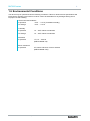
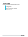
Version 2.0 User Manual IT-Infrastructure RAC2000 series Index 1 1.1 1.2 1.3 1.4 1.5 1.6 1.7 1.8 1.9 2 2.1 2.2 2.3 2.4 2.5 3 3.1 3.2 3.3 3.4 4 Remarks Relevant Documentation for this device Used Symbol Explanation Data, Figures, Modifications Trademarks Copyright Environmental Conditions Standards Equipment Version Scope of Delivery Notes on Operation & Safety Sicherheitshinweise Operation Location Damage Caused By Improper Use Warranty / Repair GENERAL NOTES ON THE 5GHZ VERSION (802.11 A / 802.11 H) ETSI Mounting Mounting options External Device Dimensions Mounting options Layout for Device Installation System Features 3 3 3 3 3 3 4 5 5 6 7 7 8 8 8 9 10 10 11 12 13 14 4.1 General LED Status 4.1.1 PWR / CUT & ALARM / VPN 3G 4.2 Operational LED Status Displays 4.2.1 Status Display Activities when Booting 4.2.2 Status display activities when resetting to default settings 4.2.3 Status display activities with Firmware Updates 4.3 Device Overview 4.3.1 24 VDC Power Supply 4.3.2 HOST (RJ45) 4.3.3 USB-Connections 4.3.4 SMARTCARD READER according to ISO 7816 14 15 16 16 17 18 19 20 20 20 21 5 22 5.1 5.2 5.3 5.4 6 6.1 7 Commissioning Inititial-Commissioning Manual Network adapter configuration Settings for use with Internet Explorer 8 Calling up the Device Web Interface 22 23 24 26 Approvals 28 Directives 31 Technical Details 32 RAC2000 series 8 8.1 8.2 9 2 Service & Support 33 ads-tec Support Company adress 33 33 Declaration of CE-Conformity © ads-tec GmbH • Heinrich-Hertz-Str. 1 • D-72622 Nürtingen 1 RAC2000 series 3 1 Remarks 1.1 Relevant Documentation for this device The following documents are essential for setting up and operating this device: User Manual (This Documentation): Contains information for installation, commissioning and operating the device along with technical data of the device hardware. Qucik Start Guide: Quick Install Guide for fast commissioning. 1.2 Used Symbol Explanation Warning: The "Warning" symbol refers to activities which might cause personal injury or damage to the hardware or software! Note: The "Note" symbol familiarises you with conditions to be observed in order to ensure flawless operation. Additionally, hints and advice are given for a more efficient use of the device and for software optimisation. 1.3 Data, Figures, Modifications All texts, data and figures are non-binding. We reserve the right of modification in accordance with technological progress. At that point in time when the products leave our premises, they comply with all currently applicable legal requirements and regulations. The operator/operating company is independently responsible for compliance with and observance of any subsequently introduced technical innovations and new legal requirements, as well as for all usual obligations of the operator/operating company. 1.4 Trademarks It is hereby notified that any software and/or hardware trademarks further to any company brand names as mentioned in this User’s Guide are all strictly subject to the various trademark, brand name and patent protection rights. Windows®, Windows® CE are registered trademarks of Microsoft Corp. Intel®, Pentium®, Atom™ , Core™2 are registered trademarks of Intel Corp. IBM®, PS/2® and VGA® are registered trademarks of IBM Corp. CompactFlash™ and CF™ are registered trademarks of SanDisk Corp. RITTAL® is a registered trademark of the Rittal Werk Rudolf Loh GmbH & Co. KG. Any further additional trademarks and/or brand names herein, be they domestic or international, are hereby duly acknowledged. 1.5 Copyright This manual, including all contained figures, is protected by copyright law. Any use for third parties noncompliant with the copyright provisions is prohibited. Any reproduction, translation as well as electronic and photographic archiving and modification shall only be permitted after explicit written authorisation by adstec GmbH. Any party in violation of this provision shall be obliged to damage compensation. © ads-tec GmbH • Heinrich-Hertz-Str. 1 • D-72622 Nürtingen RAC2000 series 4 1.6 Environmental Conditions The device may be operated under the following conditions. Failure to observe these specifications will terminate any warranty for this device. Ads-tec cannot be held liable for any damages arising due to improper use and handling. Environmental Conditions in Operation -20°C ... + 55°C (if installed vertically) For Storage -20°C ... + 55°C Humidity In Operation For Storage •Vibrations In Operation •Shock resistance In Operation © ads-tec GmbH • Heinrich-Hertz-Str. 1 • D-72622 Nürtingen 10 … 85% without condensate 10 … 85% without condensate 1 G, 10 … 500 Hz (DIN EN 60068-2-6) 5 G, with a half-wave of 30 ms duration (DIN EN 60068-2-29) RAC2000 series 5 1.7 Standards This device complies with the requirements and protective aims of the following EC regulations: Standards This device meets the test requirements for granting the CE sign according to the European test standards EN 61000-6-4 and EN 61000-6-2 This device complies with the test requirements in accordance with EN 60950 (VDE0805, IEC950) "Safety of Information Technology Equipment" The device meets the EN 60068-2-6 test requirements (sinus excitation). This device meets the EN 60068-2-27 test requirements (shock resistance test) Note: A respective conformity declaration for the authority in charge is available at the manufacturer and may be viewed on request. All connected components, as well as cable connections must also meet these requirements for compliance with the EMC legislation. For this reason, screened bus and LAN cables including screened connectors must be used and installed according to the instructions in this user manual. 1.8 Equipment Version This device is offered in 2 different equipment versions. Equipment Version RAC2110 RAC2120 24V DC X X RJ45 X X 1 WLAN Modul X 2 WLAN Module X RJ45 ist ein Ethernet-Standard, wie er häufig in der Telekommunikationswelt verwendet wird. Die Übertragungsart entspricht 10/100/1000Mbits half & full DUPLEX 1000 BASE-TX. © ads-tec GmbH • Heinrich-Hertz-Str. 1 • D-72622 Nürtingen RAC2000 series 1.9 Scope of Delivery Please check that all of the following components are contained in the packaging: Scope of Delivery RAC2000 series 1 x Rugged Access Client 1 x 3 pin plug Installation screws Quick Guide Commissioning / Quick Guide Mounting GNU General Public License © ads-tec GmbH • Heinrich-Hertz-Str. 1 • D-72622 Nürtingen 6 RAC2000 series 7 2 Notes on Operation & Safety This device contains electrical voltages and extremely sensitive components. Intervention by the user is only designated for establishing the required cable connections. The manufacturer or a service partner authorised by the manufacturer should be consulted if you plan to make further modifications. Before beginning any works on this device, it must be disconnected from the power supply. Suitable measures for avoiding any electrostatic discharges towards components must be taken. If the device is opened by an unauthorised person, hazards for the user might arise and any warranty claim will cease. General Instructions All users must read this manual and have access to it at all times Installation, commissioning and operation may only be carried out by trained and qualified staff The security instructions and the manual itself must be observed by all persons who work with this device At the location of use, the valid guidelines and regulations for accident prevention must be observed The manual contains the most important instructions on how to use this device in a safe way Appropriate storage, proper transport, installation and commissioning, as well as careful operation are prerequisites for ensuring safe and proper operation of this device Note: Only original ads-tec firmware / software is allowed for any of the adjustments and features described in this User’s Guide. Deployment of any firmware / software that has not been released by ads-tec will terminate all warranty conditions. 2.1 Sicherheitshinweise Warning: Any installation works on the device are only permitted if the power supply is switched off, and handling the device is safe. Warning: All unit mounting operations must be strictly conducted under safe, secure and zero-potential conditions. Note: Please observe applicable security measures when handling electronic components sensitive to electrostatic charges. (DIN EN 61340-5-1 / DIN EN 61340-5-2) © ads-tec GmbH • Heinrich-Hertz-Str. 1 • D-72622 Nürtingen RAC2000 series 8 2.2 Operation Location This device is designed for use in industry. You must ensure compliance with the specified environmental conditions. Using the device in non-specified environments, e.g. on board ship or in areas containing explosive vapours, gases or gas mixes, as well as in extreme heights, is prohibited. Warning: If this device is used outdoors, it must be located inside the protective area of a lightning arrester. You have to make sure that all conductive systems introduced from outdoor areas and connected to the device are equipped with a lightning arrester/potential equalisation system. This device may only be switched on after the required ambient temperature is reached in order to avoid condensate accumulation. The same applies if the device has previously been exposed to extreme temperature variations. To avoid overheating in operation: Do not expose the device to any direct radiation by sunlight or any other light or heat source. Warning: This is a Class A device. In a domestic environment this device may cause radio frequency (RF) interference, in which case the user may be required to take adequate measures. Warning: To avoid personal injury resulting from RF energy, a minimum distance of 20 cm must be maintained to the device Warning: For the prevention of water condensate accumulation, the unit should be turned ON only when it reaches ambient temperature. This particularly applies when the unit is subject to extreme temperature fluctuations and/or variations. Avoid overheating during unit operations; the unit must not be exposed to direct sunlight or any other direct light or heat sources. 2.3 Damage Caused By Improper Use This device must immediately be shut down and protected from any accidental commissioning if the operating system shows any obvious damage caused by, for example, improper operating or storage conditions, or by improper use or handling. 2.4 Warranty / Repair During the warranty period, any repair must only be carried out by the manufacturer or by a person authorised by the manufacturer. © ads-tec GmbH • Heinrich-Hertz-Str. 1 • D-72622 Nürtingen RAC2000 series 2.5 GENERAL NOTES ON THE 5GHZ VERSION (802.11 A / 802.11 H) ETSI General Notes This device has been certified for use with channels in the 5 GHz band in accordance with ETSI EN 301 893 V1.5.1. With respect to this, users must observe the following notes: The Access Client is using TPC on all 5 GHz channels by default with both, indoor and outdoor configuration as well. For this reason, the devices can always be operated with a maximum transmission power of 23 dBm. 802.11a outdoor channels are not available for a fixed setup. Note: All channels for the 5 GHz band are automatically detected via auto setup. Warning: These notes must be observed when operating the devices: • This device does not provide a "safe" data transmission medium • These devices do not allow establishment of any real time systems. • These devices do not have any deterministic system behaviour • No MIN/MAX roaming time is guaranteed Adherence to settings with the applicable requirements by the regulatory authority and observance of valid antenna amplification limits is the responsibility of the operator/operating company. © ads-tec GmbH • Heinrich-Hertz-Str. 1 • D-72622 Nürtingen 9 RAC2000 series 10 3 Mounting 3.1 Mounting options This device is designed for industrial use and can be used in all places, where the required ambient conditions are not disregarded. For reason of an easier installation and better operation, this device should be installed in a place where there is no interference with the radio characteristics, if possible. Radio characteristics are primarily affected by iron beams and massive concrete walls. Warning: Avoid overheating in operation. Never expose the device to any direct irradiation by the sunlight or any other light source. IP 65 protection is only achieved with proper installation. The tolerance in drawings amounts to +/1.5 mm. © ads-tec GmbH • Heinrich-Hertz-Str. 1 • D-72622 Nürtingen RAC2000 series 3.2 External Device Dimensions Abb. 1: © ads-tec GmbH • Heinrich-Hertz-Str. 1 • D-72622 Nürtingen 11 RAC2000 series 12 3.3 Mounting options This device is designed for installation inside a switching cabinet. It can be installed at the place of installation by using the supplied M4 x 20 Allen screws. Hole distances can be determined by using the drilling template. © ads-tec GmbH • Heinrich-Hertz-Str. 1 • D-72622 Nürtingen RAC2000 series 3.4 Layout for Device Installation Drilling template Abb. 2: Note: The shown installation layout is not a 1:1 scale view. Please find the 1:1 scale figure in the Installation section of the Quick start guide. Note: The hole diameter for the fixing screws should be at least 5mm. © ads-tec GmbH • Heinrich-Hertz-Str. 1 • D-72622 Nürtingen 13 RAC2000 series 14 4 System Features 4.1 General LED Status The status of different interfaces is shown by the integrated LEDs. This allows the device status to be diagnosed directly at the place of use. The available device status displays are shown in the overview. LED Status representation off green gren flashing red orange orange flashing Note: Subsequently described LED displays are abbreviated as follows: Left-hand LED = LINK (readiness for operation) Right-hand LED = ACT (activity) © ads-tec GmbH • Heinrich-Hertz-Str. 1 • D-72622 Nürtingen RAC2000 series 15 4.1.1 PWR / CUT & ALARM / VPN 3G Abb. 3: WLAN (1) / (2) Signal Action Left LED Link Device is searching for available WLAN networks. Left LED Link Device is iconnected t to WLAN network Right LED ACT There is no traffic between the device and the remote station Right LED ACT Displays the traffic between the device and remote. HOST Signal Action Left LED Link The interface is not connected to a remote station Left LED Link The interface is connected to a remote site and is ready for use Right LED ACT There is no traffic between the device and the remote station Right LED ACT Displays the traffic between the device and remote. POWER Signal Action The device is not powered The device is supplied with power via Power and is ready The device has a fatal firmware error. Its can only be solved by adstec © ads-tec GmbH • Heinrich-Hertz-Str. 1 • D-72622 Nürtingen RAC2000 series 16 4.2 Operational LED Status Displays 4.2.1 Status Display Activities when Booting The booting process starts a soon as the RAC2000 device is connected with a power source. You can check if the device boots by using the HOST LEDs. By means of the following diagram, the correct booting process can be traced by watching the flashing frequency of the LEDs. No HOST cable is connected in this case. Note: If the WLAN interface is enabled in the firmware, the RAC2000 device is permanently looking for WLAN networks once the booting is completed. Abb. 4: WLAN (1) / (2) Signal Left LED Link HOST Action Device is searching for available WLAN networks. Signal Action Left LED Link LEDs blink twice briefly Rechte LED Link LEDs blink twice briefly Right LED ACT LED blink fast Right LED ACT LED turns out POWER Signal Action The device is supplied with power via Power and is ready © ads-tec GmbH • Heinrich-Hertz-Str. 1 • D-72622 Nürtingen RAC2000 series 17 4.2.2 Status display activities when resetting to default settings By using the default setting button on the rear of the device, the RAC2000 can be reset to the default settings regardless of the configuration. The default setting button must be pushed, and the device then be switched on, in order to reset the device to the default settings. The default setting button must be pushed for approx. 20 seconds. As soon as both HOST LEDs flash, you can release the button. No HOST cable is connected in this example. By means of the following diagram, the correct factory default process can be traced by watching the flashing frequency of the LEDs. WLAN (1) / (2) Signal Left LED Link HOST Action Device is searching for available WLAN networks. Signal Action Left LED Link LEDs blink twice briefly Rechte LED Link LEDs blink twice briefly Lft LED ACT LED turns out Right LED ACT LED turns out POWER Signal Action The device is supplied with power via Power and is ready © ads-tec GmbH • Heinrich-Hertz-Str. 1 • D-72622 Nürtingen RAC2000 series 18 4.2.3 Status display activities with Firmware Updates A firmware update can be made by using the web interface. The actual process of updating might take a few minutes. By means of the following diagram, the correct firmware update process can be traced by watching the flashing frequency of the LEDs. Abb. 5: WLAN (1) / (2) Signal Linke LED Link HOST Action Device is searching for available WLAN networks. Signal Action Link / Act LEDs are flashing with fast speed Link / Act LINK turns off / ACT is flashing Link / Act LINK illuminates constantly / ACT turns off Link / Act LINK illuminates constantly / ACT is flashing slowly Link / Act LINK illuminates constantly / ACT is flashing with high speed Link / Act LINK illuminates constantly / ACT turns off Subsequently, the web interface can be started by using the "Attempt to reconnect" menu item POWER Signal Action The device is supplied with the voltage via POWER and is ready for operation. © ads-tec GmbH • Heinrich-Hertz-Str. 1 • D-72622 Nürtingen RAC2000 series 19 4.3 Device Overview Front view Rear view Abb. 6: The device has the following connections: 1. 2. 3. 4. 5. 1 x Power 24V DC power supply (2-pin COMBICON connector) 1 x HOST RJ45 1 x Factory Default 1 x SIM Card Reader 2 x USB © ads-tec GmbH • Heinrich-Hertz-Str. 1 • D-72622 Nürtingen RAC2000 series 20 4.3.1 24 VDC Power Supply The power supply voltage is supplied via a feed-through clamp including screw connection (figure shows socket in the device). Pin-Number Signal-Name 1 24V DC 2 0V DC Technical Data of the Power Supply • Input: 7…36V DC 4.3.2 HOST (RJ45) Pin-Number Signal-Name 1 TX + 2 TX - 3 RX + 4 NC 5 NC 6 RX - 7 NC 8 NC 4.3.3 USB-Connections The SIM card reader is used for storing configuration data. Pin-Number Signal-Name 1 VDC 2 D- 3 D+ 4 GND © ads-tec GmbH • Heinrich-Hertz-Str. 1 • D-72622 Nürtingen RAC2000 series 21 4.3.4 SMARTCARD READER according to ISO 7816 The SIM card reader is used for storing configuration data. Pin-Nummer Signal-Name 1 VCC 5 Volt 2 RESET 3 CLOCK 4 NC 5 GND 6 NC 7 I/O 8 NC © ads-tec GmbH • Heinrich-Hertz-Str. 1 • D-72622 Nürtingen RAC2000 series 22 5 Commissioning 5.1 Inititial-Commissioning Achtung: The initial installation of this device can only be performed by using the RJ45 interface labelled with HOST. A RJ45 PATCH CABLE IS REQUIRED FOR INITIAL CONFIGURATION. Connecting the 24 V DC power source The power for this device can be supplied by a 24V DC (2-pin connector) power supply. The corresponding COMBICON connector is included in the scope of delivery. Connect the device with a suitable power supply unit. RJ45 network cable connection For initial installation it is essential to establish a connection between this device and a PC by using a RJ45 network cable. To connect the device with a PC: Device HOST connector <-> PC LAN connector © ads-tec GmbH • Heinrich-Hertz-Str. 1 • D-72622 Nürtingen RAC2000 series 23 5.2 Manual Network adapter configuration Note: The notes below have been created by using Windows XP®. Should you use a different operating system, the directory paths and properties described here might vary. Open the Properties tab of the network adapter you are using. The directory path is: Start> Settings> Network connections> LAN connections> Properties. Select the following option in the pop-up dialogue: Internet protocol (TCP/IP); then click on Properties . Abb. 7: Here select the following item: Use following IP address Access to the device will only be enabled once the following parameters have been entered as the fixed IP address, or if the computer is located in the same subnet area: IP Address: 192.168.0.100 Note: (The last section of digits must represent a number between 1 and 253; the value " 100" was selected in the example) Once the IP address is entered, you have to input the Subnet mask address. If you click into the Subnet mask box, the correct address is automatically entered. Subnet Mask: 255.255.255.0 You can now close the dialogue boxes by pushing the "OK" button. © ads-tec GmbH • Heinrich-Hertz-Str. 1 • D-72622 Nürtingen RAC2000 series 24 5.3 Settings for use with Internet Explorer 8 Warning: If Internet Explorer 8 is used, issues with the web interface might occur. If you experience any problems, the IP address of the device must be entered in the Local Intranet list in order to display the web interface correctly. Open Internet Explorer and navigate to the Security tab with the following directory path: ToolsInternet optionsSecurity Switch to the Local Intranet tab and click there on Sites.. Abb. 8: Then click on Advanced. Abb. 9: In the Add this website to the zone address line, enter the device IP address and confirm this step with Add. Default IP address: http://192.168.0.254 © ads-tec GmbH • Heinrich-Hertz-Str. 1 • D-72622 Nürtingen RAC2000 series 25 The entered IP address should now appear in the list under Websites. Abb. 10: © ads-tec GmbH • Heinrich-Hertz-Str. 1 • D-72622 Nürtingen RAC2000 series 26 5.4 Calling up the Device Web Interface To access and open the device web interface, start up your web browser. In the browser’s address bar, enter the following IP address then confirm with Enter http://192.168.0.254 Login Once the IP address has been entered with success, the login prompt appears. In the login prompt, entry of the default settings is required. The default configuration in just-delivered conditions is: User Name : admin Password : admin Confirm your entries by clicking on: OK Abb. 11: Note: If the login prompt does not appear, check to ensure that the device has been connected via a RJ45/LWL optic fibre connection cable. Otherwise, connect the device up to a PC (Device LAN-in/LAN-out connection <> PC LAN connection). If there still is no connection to the firewall login prompt, it is necessary to check the proxy and local firewall settings. It often occurs that also local subnet addresses ( e.g. 192.168.x.x) are diverted to a proxy server. In this case it is possible to select the “Bypass proxy server for local addresses” option to enter the © ads-tec GmbH • Heinrich-Hertz-Str. 1 • D-72622 Nürtingen RAC2000 series 27 address in question. Finally, the device web interface will come up on screen. Abb. 12: © ads-tec GmbH • Heinrich-Hertz-Str. 1 • D-72622 Nürtingen RAC2000 series 28 6 Approvals Note: Some restrictions affecting the scope of functions of this device might occur due to country specific regulations. Countries Identification 2,4 - 2,4835 GHz IEEE 802.11b/g Belgium X Germany X Finland X Greece X Ireland X Latvia X Luxembourg X Netherlands X Poland X Sweden X Slovenia X Czech Republic X Cyprus X Denmark X Estonia X France X © ads-tec GmbH • Heinrich-Hertz-Str. 1 • D-72622 Nürtingen Limitations The device in the 5150-5350 MHz may only be used indoors. TPC and DFS are mandatory for 5GHzband. Indoor use only restriction in the 5150-5350 MHz band Only indoor use for the frequency band of 5150 - 5350 MHz. Only mobile applications allowed in the 5 GHz band.RLA N/WLAN used for public service need a general autorisation from the ILR (Institut Luxembourgeois de Regulation) RAC2000 series 29 Great Britain X Italy X Lithuania X Malta X Austria X Portugal X © ads-tec GmbH • Heinrich-Hertz-Str. 1 • D-72622 Nürtingen Consequently this equipment may be placed on the local market, subject that a copy of the Declaration of Conformity is submitted to this Authority by the person intending to market the equipment. Information: for this type of applications an integral or dedicated antenna is required in the frequency of 52505350MHz and 54705725MHz DFS and TPC are mandatory If the equipment does not have DFS implemented the use will be limited to the frequency of 51505250MHz, with a maximum output power limited of e.i.r.p of 0.25mW/25kHz for each 25kHz.the maximum output power should be in E.I.R.P RAC2000 series 30 Slowakia X Spain X Hungary X Switzerland X Norway X Iceland X © ads-tec GmbH • Heinrich-Hertz-Str. 1 • D-72622 Nürtingen Int the Slovak Republic operation of the wireless LAN equipment is allowed in the frequency band 2400 - 24835 MHz against the conditions laid down in the General authorisation No. VPR-01/2001 (20 dBM EIRP) issued by the Telecommunications Office of the SR. In the frequency band 5150 - 5350 MHz operation of WLAN equipment is allowed against the conditions laid down in the General authorisation No.: VPR-03/2004 (indoor only: 5150 5350 with DFS: 200mW EIRP with TPC, 120mW EIRP without TPC; 5150 5250 without DFS: 120mW EIRP with TPC, 60mW EIRO without TPC)In the frequency band 5470 - 5725 MHz operation of WLAN equipment is allowed against the conditions laid down in the General authorisation No.: VPR-07/2004 (1W EIRP, DFS + TCP is required) RAC2000 series 31 6.1 Directives RAC 2110 RAC 2120 in their versions as brought into circulation by ads-tec GmbH comply with the regulations of the following EU Directives: 99/5/EEC Directive of the European Parliament and the European Council for harmonization of the legislations of individual EU countries with respect to Radio & Telecommunication Terminal Equipment (RTTE) and for mutual recognition of equipment conformity. Conformity with the basic requirements of this directive is proven by compliance with the following standards: EN 60950 Safety of information technology equipment EN 301489-1 Electromagnetic compatibility (EMC) and radio spectrum matters (ERM); Electromagnetic compatibility (EMC) standard for radio equipment and services EN 301489-17 Electromagnetic compatibility and radio spectrum matters (ERM); Electromagnetic compatibility (EMC) standard for radio equipment; Part 17: Specific conditions for Broadband Data Transmission Systems EN 300328 Electromagnetic compatibility (EMC) and radio spectrum matters (ERM) EN 301893 Broadband Radio Access Networks (BRAN); 5 GHz high performance RLAN EN 50371 Generic standard to demonstrate the compliance of low power electronic and electrical apparatus with the basic restrictions related to human exposure to electromagnetic fields (10MHz - 3GHz) 1999/519/EC Council Recommendation of 12 July 1999 on the limitation of exposure of the general public to electromagnetic fields (0 Hz to 300 GHz) Any equipment connected to the system must also comply with all relevant safety regulations. This EC Conformity Declaration is kept available for the authorities in charge in accordance with above mentioned EEC directives at the following location: ads-tec GmbH Raiffeisenstraße 14 D-70771 Leinfelden-Echterdingen / Oberaichen Although this declaration certifies the conformity with all mentioned directives, it cannot be considered as a warranty of any specific features. © ads-tec GmbH • Heinrich-Hertz-Str. 1 • D-72622 Nürtingen RAC2000 series 32 7 Technical Details Device Data RAC2000 series Operating System Embedded LinuX Configuration Protocol http, https Power Supply 24V DC +/- 20%, redundant power input Interfaces 1 x RJ45 100BaseTx FD 1 x SIM Reader, 2 x Mini-PCI Connection, 2x USB External Device Dimensions 137 mm x 98mm x 46mm Weight ca. 0,5 kg Protection Class Front sided IP65 Maximum current consumption max. 400 mA at 24V DC ambient temperature in Operation vertically) -20°C ... + 55°C (if installed For Storage -20°C ... + 55°C Note: For detailed information of this device see our website http://www.ads-tec.com. © ads-tec GmbH • Heinrich-Hertz-Str. 1 • D-72622 Nürtingen RAC2000 series 33 8 Service & Support The ads-tec company and their partner companies offer a comprehensive service and support to your customers providing a quick and professional support in case of any question with respect to ads-tec products and components. Since the devices from ads-tec company are also used by partner companies, these devices might be configured according to specific customer requirements. Should any question or issue with respect to specific configurations and software installations arise, it can only be resolved by the system manufacturer. For devices not directly purchased from ads-tec, we cannot be responsible for the support. In this case, the support is provided by our partner company. 8.1 ads-tec Support The ads-tec support team is available for direct clients from Monday to Friday from 08:30 AM to 05:00 PM using the following phone number: Tel: +49 7022 2522-202 Fax: +49 7022 2522-2602 E-Mail: [email protected] 8.2 Company adress ads-tec GmbH Heinrich-Hertz-Str. 1 D-72622 Nürtingen Germany Phone: +49 (0) 7022 2522-0 Fax: +49 (0) 7022 2522-400 E-Mail: [email protected] Home: www.ads-tec.de © ads-tec GmbH • Heinrich-Hertz-Str. 1 • D-72622 Nürtingen 9 Declaration of CE-Conformity RAC2110 RAC2000 series RAC2120 © ads-tec GmbH • Heinrich-Hertz-Str. 1 • D-72622 Nürtingen 2