1
Invitation to Tender ES-15-08
Bear Lake Water System Upgrades
APPENDIX ‘A’
SPECIFICATIONS
Section 01535 - Temporary Facilities
Section 01561 - Environmental Protection
Section 01570 - Traffic Regulation
Section 01721 - Project Record Documents
Section 02000 - Reference Specifications
Section 02100 - Measurement and Payment
Section 02111 - Clearing and Grubbing
Section 02211 - Landscape Grading
Section 02223 - Excavation, Trenching and Backfilling
Section 02224 - Roadway Excavation
Section 02226 - Aggregates
Section 02231 - Reshaping Roadbed
Section 02233 - Granular Base
Section 02498 - Geosynthetics
Section 02512 - Hot Mix Asphalt Concrete
Section 02546 - Asphalt Prime
Section 02666 - Waterworks
Section 02921 - Topsoil and Finish Grading
Section 02933 - Seeding
Section 02934 - Hydraulic Seeding
Section 02938 - Sodding
Section 02950 - Planting of Trees, Shrubs and Ground Covers
Section 03200 - Concrete Reinforcement
Section 03300 - Cast in Place Concrete
Section 03400 - Precast Concrete
Section 15000 - Packaged Equipment
Section 16000 - Electrical and Instrumentation
47111.00
MASTER
MUNICIPAL
SPECIFICATIONS
1.0
GENERAL
TEMPORARY
FACILITIES
SECTION 01535
PAGE 1
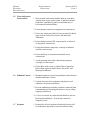
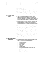
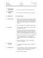
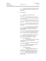
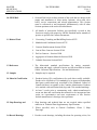
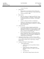
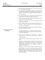
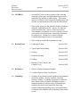
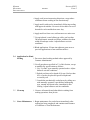
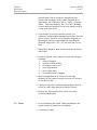
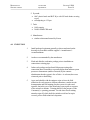
.1 Section 01535 addresses general requirements for
temporary utilities and construction facilities not
incorporated into the final or permanent work. This
section must be referenced to and interpreted
simultaneously with all other sections pertinent to the
works described herein.
.2 Comply with General Conditions, Clauses 4.4,
Temporary Structures and Facilities.
1.1
Section Includes
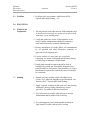
.1 Temporary utilities.
.2 Construction facilities.
.3 Office and sheds.
.4 “Portaloos”
.5 Project identification.
1.2
Installation and
Removal
.1 Provide temporary utilities and construction facilities in
order to execute work expeditiously.
1.3
Dewatering
.1 Provide temporary drainage and pumping facilities to
keep excavations and site free from standing water.
1.4
Sanitary Facilities
.1 Provide sufficient sanitary facilities for workers in
accordance with local health authorities.
1.5
Water Supply
.1 Provide adequate supply of potable water.
1.6
Site Storage/
Loading
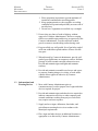
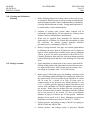
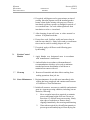
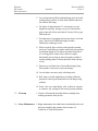
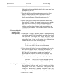
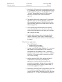
.1 Confine work and operations of employees in
accordance with Contract Documents. Do not
unreasonably encumber premises with products. Areas
off the end of Cub and Cinnamon Streets shall be
available to the Contractor for construction staging,
including materials lay-down, provided areas occupied by
the Contractor for such use are not damaged. Such areas
will be limited and shall be agreed with the Community
representative prior to their initial use.
MASTER
MUNICIPAL
SPECIFICATIONS
TEMPORARY
FACILITIES
SECTION 01535
PAGE 2
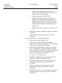
.2 Do not load or permit to load any part of work with a
weight or force that will endanger the work.
1.7
Temporary Power
and Light
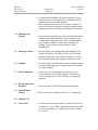
1.8 Construction
Parking
1.9
Hoarding
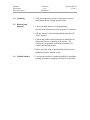
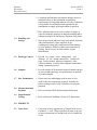
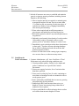
.1 Arrange for connection with appropriate utility company.
Pay all costs for installation, maintenance, and removal.
.1 On-site parking will only be permitted if it does not
disrupt the movements of the citizens or the performance
of the work. Otherwise parking shall be as indicated in
1.6 above.
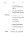
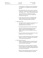
.1 Provide hoarding as shown on Contract Drawings
protecting public and private property from injury or
damage. Lockable gates are not specifically required for
access to the site.
1.10 Security
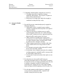
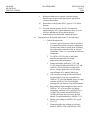
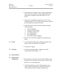
.1 Provide and pay for responsible security personnel to
guard site and contents of site after working hours and
during holidays.
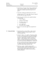
1.11 Site Offices
.1 The Contractor is not specifically required to provide a
Contract Administrator’s office for the site.
.2 If supplied, provide and maintain in clean condition
during progress of work, adequately lighted, heated, and
ventilated Contractor’s office with space for filing and
layout of Contract Documents and Contractor’s normal
site office staff.
1.12 Construction Sign
.1 Provide and erect, within 3 weeks of signing Contract, a
project sign in a location designated by Contract
Administrator.
.2 Construction sign 1.2m x 2.4m, of wood frame and
plywood construction painted with exhibit lettering
produced by a professional sign painter.
.3 Indicate on sign, name of Owner, Contract Administrator,
and Contractor, of a design style approved by Contract
Administrator.
MASTER
MUNICIPAL
SPECIFICATIONS
TEMPORARY
FACILITIES
SECTION 01535
PAGE 3
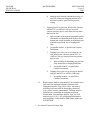
.4 Maintain sign in good condition for duration of work.
Clean periodically.
.5 No other sign or advertisements, other than warning
signs, are permitted on site.
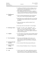
1.13 Public Notice
.1 Advise residents and/or other parties within the affected
area of planned construction activities and schedule.
Coordinate with and obtain Contract Administrator’s
approval before delivery or mailing of public notices.
1.14 Site Access
.1 It may be necessary to remove the fence at the ball
diamonds to access and execute the work. If this is so,
the fence shall be carefully removed and replaced on
completion of the underground work to an equal or better
condition than before the work began. If this cannot be
achieved, replace the fence as required.
1.15 Site Conditions
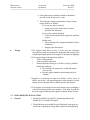
.1 Take detailed photographs of all parts of the work and
provide to the Contract Administrator electronically prior
to any work commencing - as a record of existing site
conditions. Take additional photographs if required by
the Contract Administrator.
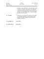
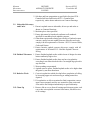
1.16 Payment
.1 Payment for all work performed under this Section will
be incidental to payment for work described in other
Sections unless shown otherwise in the Schedule of
Quantities and Prices.
2.0 PRODUCTS
NOT USED
3.0 EXECUTION
NOT USED
MASTER
MUNICIPAL
SPECIFICATIONS
1.0
GENERAL
ENVIRONMENTAL
PROTECTION
SECTION 01561
PAGE 1
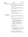
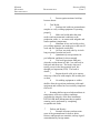
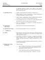
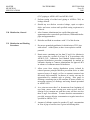
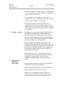
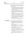
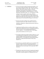
.1 Section 01561 addresses general requirements for
environmental protection. This section is not intended to
identify all and/or specific requirements. This section
must be referenced to and interpreted simultaneously with
all other sections pertinent to the works described herein.
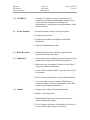
.2 Comply with General Conditions, Clause 20.4,
Environmental Laws.
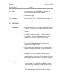
1.1
Fires
1.2 Disposal of
Wastes
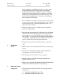
.1 Fires and burning of rubbish on site not permitted without
approval of the Contract Administrator. All fires to
conform to Provincial and Municipal regulations.
.1 Do not bury rubbish and waste materials on site unless
approved by Contract Administrator.
.2 Do not dispose of waste or volatile materials, such as
mineral spirits, oil, or paint thinner into watercourses,
storm, or sanitary sewers.
1.3
Drainage
.1 Provide temporary drainage and pumping as necessary to
keep excavations and site free from water.
.2 Do not discharge water containing suspended materials
into watercourses, sewer, or drainage systems.
.3 Control disposal or runoff of water containing suspended
materials or other harmful substances in accordance with
Federal, Provincial, and Municipal requirements.
1.4
Site Clearing and
Plant Protection
.1 Protect trees and plants on site and adjacent properties
where shown on Contract Drawings.
.2 Protect roots of designated trees to dripline during
excavation and site grading to prevent disturbance or
damage. Avoid unnecessary traffic, dumping, and
storage of materials over root zones.
.3 Minimize stripping of topsoil and vegetation.
.4 Restrict tree removal to areas indicated or designated by
Contract Administrator.
MASTER
MUNICIPAL
SPECIFICATIONS
1.5
Work Adjacent to
Watercourses
ENVIRONMENTAL
PROTECTION
SECTION 01561
PAGE 2
.1 Work around watercourses shall be done in accordance
with the most recent version of the “Land Development
Guidelines” published by the Provincial Ministry of
Environment Lands and Parks.
.2 Do not operate construction equipment in watercourses.
.3 Do not use watercourse beds for borrow material without
approval from Federal, Provincial, and Municipal
Authorities.
.4 Do not dump excavated fill, waste material, or debris in
or adjacent to watercourses.
.5 Design and construct temporary crossings to minimize
erosion to watercourses.
.6 Do not skid logs or construction materials across
watercourses.
.7 Avoid spawning beds when constructing temporary
crossings of watercourses.
.8 Do not blast under water or within 100m of spawning
beds without approval from Federal, Provincial, and
Municipal authorities.
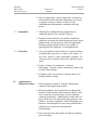
1.6
Pollution Control
.1 Maintain temporary erosion and pollution control features
installed under this Contract.
.2 Control emissions from equipment and plant to local
authorities emission requirements.
.3 Prevent sandblasting and other extraneous materials from
contaminating air beyond application area, by providing
temporary enclosures.
.4 Cover or wet down dry materials and rubbish to prevent
blowing dust and debris. Provide dust control for
temporary roads.
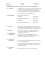
1.7
Payment
.1 Payment for all work performed under this Section will
be incidental to payment for work described in other
MASTER
MUNICIPAL
SPECIFICATIONS
ENVIRONMENTAL
PROTECTION
SECTION 01561
PAGE 3
Sections unless shown otherwise in the Schedule of
Quantities and Prices.
1.8
Inspection and
Testing
2.0
PRODUCTS
2.1
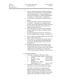
Silt Barrier Fence
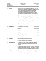
.1 Refer to General Conditions, Clause 4.12, Inspections.
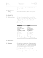
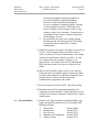
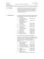
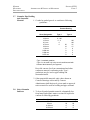
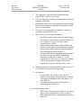
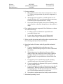
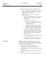
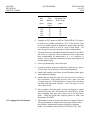
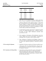
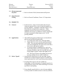
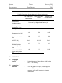
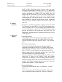
.1 Silt fence to be manufactured from a woven, silt film
geotextile material with a shiny to smooth surface texture
designed to reduce velocity of runoff to point that
suspended particles settle out due to reduction of
hydraulic energy.
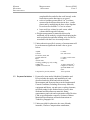
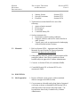
.2 Minimum Requirements:
PROPERTY
VALUE
Grab Tensile
500N
Mullen Burst
1900kPa
Elongation at Break
25% Maximum
Opening
600µm maximum
U.V. Rating @ 500hrs
90% Retained
Efficiency
> 75% minimum
Construction
Woven (tape)
Texture
Smooth, Shiny
Posts
4 x 4 cm, treated
Post Spacing (centres)
2 meter maximum
Permittivity
10L/s/m2
Above values are “Minimum Average Roll Values”
3.0
EXECUTION
3.1
Placement
.1 Place silt barrier in a manner that will intercept runoff at
or close to right angles to flow. In areas where problem
is severe, erect two or more silt barriers parallel to each
other, until required degree of control is achieved.
.2 Fence height as specified on Contract Drawings.
.3 Position posts in such a manner that fence structure
remains naturally taut and placed or driven a minimum of
MASTER
MUNICIPAL
SPECIFICATIONS
ENVIRONMENTAL
PROTECTION
SECTION 01561
PAGE 4
500mm into ground. Posts to always be positions
downstream.
.4 Where a 500mm depth is impractical or impossible
adequately secure or brace posts to prevent overturning of
fence due to sediment loading.
.5 Bury excess geotextile at bottom of silt fence minimum
of 150mm in trench located upstream such that no flow
can pass under fence.
.6 Splice subsequent lengths of barrier only at support post
locations. Splice by wrapping geotextile fabric
completely around each of two abutting support posts, as
detailed on Contract Drawings, such that gap between
abutting posts is completely covered by both sections of
fabric.
3.2
Quantities
.1 Limit silt fence to handle area equivalent to maximum
100m2 per 3m of fence.
.2 Do not use where site slope is steeper than 3:1, and water
flow rates exceed 0.03m2/s per 3m of fence.
.3 Silt barrier to have efficiency > 75%. Employ successive
parallel fences to achieve required degree of control.
3.3 Maintenance
.1 maintain integrity of silt fences as long as necessary to
contain sediment runoff. Inspect all temporary silt fences
immediately after each rainfall and at least daily during
prolonged rainfall. Immediately correct any deficiencies.
In addition, make daily review of location of silt fences in
areas where construction activities have changed natural
contours and drainage runoff to ensure that silt fences are
properly located for effectiveness. Where deficiencies
exist, install additional silt fences. Should silt fence
become damaged or otherwise ineffective while barrier is
still necessary, repair or replace promptly.
.2 Remove sediment deposits when deposit reaches
approximately one-third of height of silt fence or install
second silt fence upslope.
MASTER
MUNICIPAL
SPECIFICATIONS
ENVIRONMENTAL
PROTECTION
SECTION 01561
PAGE 5
.3 Do not remove silt fence until Contract Administrator
directs that it be removed.
3.4 Clean Up
.1 At completion of construction phase or as directed by
Contract Administrator, remove and dispose of any silt
accumulations, dress area to give a pleasing appearance,
and vegetate all bare areas as specified in Supplementary
Specifications or as shown on Contract Drawings.
MASTER
MUNICIPAL
SPECIFICATIONS
1.0
GENERAL
TRAFFIC
REGULATION
SECTION 01570
PAGE 1
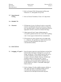
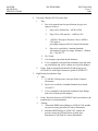
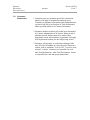
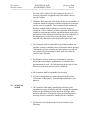
.1 Section 01570 addresses the general requirements for
accommodation of roadway traffic during construction.
This section must be referenced to and interpreted
simultaneously with all other sections pertinent to the
works described herein.
.2 During progress of the Works, make adequate provision
to accommodate normal traffic along streets and
highways immediately adjacent to or crossing the Works
so as to cause minimum of inconvenience to general
public.
.3 Give minimum 48hr notice or as otherwise required by
local bylaws to local police, fire departments, emergency
services, and municipal works authorities prior to
beginning construction and comply in all respects with
their requirements.
.4 Inform all owners or occupants of properties where
access is affected in advance of proposed road and/or
sidewalk closures.
.5 The Regional District of Fraser Fort George has a permit
from the Ministry of Transportation to undertake utility
works within a highway right of way. The contractor
shall comply with the requirements of the permit and with
the requirements of MoT for the work of this contract
generally.
1.1
1.2
Reference
Standard
Protection of
Public Traffic
.1 Regulate traffic in general accordance with municipal
requirements except where specified otherwise and in
compliance with specific requirements stipulated herein.
.1 Comply with requirements of the “Traffic Control
Manual for Work on Roadways”, published by the British
Columbia Ministry of Transportation and Highways, for
regulation of vehicle and pedestrian traffic or use of
roadways upon or over which it is necessary to carry out
work or haul materials or equipment.
.2 When working on travelled way:
MASTER
MUNICIPAL
SPECIFICATIONS
TRAFFIC
REGULATION
SECTION 01570
PAGE 2
.1 Place equipment in position to present minimum of
interference and hazard to travelling public.
.2 Keep equipment units as close together as working
conditions will permit and preferably on same side of
travelled way.
.3 Do not leave equipment on travelled way overnight.
.3 Do not close any lanes of road or highway without
approval of Contract Administrator. Before re-routing
traffic erect suitable signs and devices as approved by the
Contract Administrator. Provide sufficient crushed
gravel to ensure a smooth riding surface during work.
.4 Keep travelled way well graded, free of pot holes, and of
sufficient width that required number of lanes of traffic
may pass.
.5 When directed by Contract Administrator, provide well
graded, gravelled detours or temporary roads to facilitate
passage of traffic around restricted construction area.
Provide and maintain signs and lights and maintain
roadway.
.6 Provide and maintain reasonable road access and egress
to property fronting along or in vicinity of work under
contract unless approved otherwise by Contract
Administrator.
1.3 Informational and
Warning Devices
.1 Meet with Contract Administrator prior to
commencement of work to prepare list of signs and other
devices required for project.
.2 Provide and maintain signs and other devices required to
indicate construction activities or other temporary and
unusual conditions resulting from project work which
may require road user response.
.3 Supply and erect signs, delineators, barricades, and
miscellaneous warning devices in accordance with
Municipal requirements.
.4 Place signs and other devices in additional locations as
appropriate or as directed by Contract Administrator.
MASTER
MUNICIPAL
SPECIFICATIONS
TRAFFIC
REGULATION
SECTION 01570
PAGE 3
.5 Continually maintain traffic control devices in use by:
.1 Checking signs daily for legibility, damage,
suitability, and location. Clean, repair, or replace to
ensure clarity and reflectance.
.2 Removing or covering signs which do not apply to
conditions existing from day to day.
1.4
Control of Public
Traffic
.1 Provide flag persons, trained and properly equipped in
following situations:
.1 When public traffic is required to pass working
vehicles or equipment which may block all or part of
travelled roadway.
.2 When it is necessary to institute one-way traffic
system through construction area or other blockage
where traffic volumes are heavy, approach speeds are
high and traffic signal system is not in use.
.3 When workmen or equipment are employed on
travelled way over brow of hills, around sharp curves
or at other locations where oncoming traffic would
not otherwise have adequate warning.
.4 Where temporary protection is required while other
traffic control devices are being erected or taken
down.
.5 For emergency protection when other traffic control
devices are not readily available.
.6 In situations where complete protection for workmen,
working equipment, and public traffic is not provided
by other traffic control devices.
.7 At each end of restricted sections where pilot cars are
required.
.2 Provide pilot cars where public traffic must use
particularly hazardous routes or where traffic is required
to remain in one lane or change periodically from one late
to another or negotiate sections of construction at
restricted speed. Equip pilot cars with orange flashing
lights and signs clearly designating vehicles as pilot cars.
.3 Provide and maintain suitable detours or temporary
access routes for pedestrian traffic, complete with
suitable warning and advisory signs.
MASTER
MUNICIPAL
SPECIFICATIONS
TRAFFIC
REGULATION
SECTION 01570
PAGE 4
.4 Maintain existing conditions for traffic throughout period
of contract except that, when required for construction
under contract and when measures have been taken as
specified herein and approved by Contract Administrator
to protect and control public traffic, existing conditions
for traffic may be restricted.
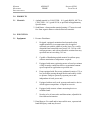
1.5
Payment
.1 Payment for all work performed under this Section will
be incidental to payment for work described in other
Sections unless shown otherwise in the Schedule of
Quantities and Prices.
2.0 PRODUCTS
NOT USED
3.0 EXECUTION
NOT USED
MASTER
MUNICIPAL
SPECIFICATIONS
PROJECT
RECORDS
DOCUMENTS
SECTION 01721
PAGE 1
1.0
GENERAL
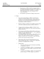
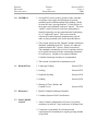
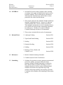
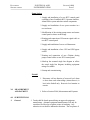
.1 Section 01721 addresses general requirements for
submittal of operating and maintenance manuals. This
section must be referenced to and interpreted
simultaneously with all other sections pertinent to works
described herein.
1.1
Section Includes
.1 Record documents, samples, and specifications.
.2 Equipment and systems.
.3 Products data, materials and finishes, and related
information.
.4 Operation and Maintenance data.
1.2 Related Sections
.1 Individual Specifications: Specific requirements for
operation and maintenance data.
1.3
.1 Prepare instructions and data by personnel experienced in
maintenance and operation of description products.
Submission
.2 Submit one copy of completed volumes in final form 15
days prior to date of performance.
.3 Copies will be returned within 15 days after date of total
Performance
.4 Revise content of documents as required final submittal.
.5 Two weeks after receipt of Contract Administrator’s
comments submit to Contract Administrator, three final
copies of operating and maintenance.
1.4 Format
.1 Organize data in form of instructional manual.
.2 Binders: 3-ring, hard cover.
.3 When multiple binders are used, correlate data into
related consistent groupings.
.4 Cover: identify each binder with printed title; list title of
Project, identify subject matter of contents.
MASTER
MUNICIPAL
SPECIFICATIONS
PROJECT
RECORDS
DOCUMENTS
SECTION 01721
PAGE 2
.5 Include Table of Contents.
.6 Provide tabbed flyleaf for each separate section.
.7 Drawings: provide with reinforced punched binder tab.
Bind in with text; fold larger drawings to size of pages.
1.5 Contents, Each
Volume
.1 Table of Contents: provide title of project; names,
addresses, and telephone numbers of Consultant and
Contractor with name of responsible parties; schedule of
products and systems, indexed to content of the volume.
.2 For each product or system: list names, addresses, and
telephone numbers of subcontractors and suppliers,
including local source of supplies and replacement parts.
.3 Product data: mark each sheet to clearly identify specific
products and component parts, and data applicable to
installation; delete inapplicable information.
.4 Drawings: supplement product data to illustrate relations
of component parts of equipment and systems, to show
control and flow diagrams.
.5 Typewritten text: as required to supplement product data.
Provide logical sequence of instructions for each
procedure, incorporating manufacturer’s instructions.
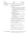
1.6
Record Documents
and Samples
.1 Maintain at site for Contract Administrator one record
copy of all Contract Documents including:
.1
.2
.3
.4
.5
.6
.7
.8
.9
Contract Drawings.
Specifications.
Field Memos.
Addenda.
Change Orders.
Reviewed shop drawings, product data, and
samples.
Field test records.
Inspection certificates.
Manufacturer’s certificates.
MASTER
MUNICIPAL
SPECIFICATIONS
PROJECT
RECORDS
DOCUMENTS
SECTION 01721
PAGE 3
.2 Store record documents and samples in site office apart
from documents used for construction. Provide files,
racks, and secure storage.
.3 Label and file in accordance with relevant Section
number. Label each document “PROJECT RECORD” in
neat, large, printed letters.
.4 Maintain Record Documents in a clean, dry and legible
condition. Do not use Record Documents for
construction purposes.
.5 Keep Record Documents and samples available for
inspection by Contract Administrator.
1.7
Recording Actual
Site Conditions
.1 Record information concurrently with construction
progress. Do not conceal work until required information
is recorded.
.2 Contract Drawings and shop drawings: legibly mark each
item to record actual construction, including:
.1
.2
.3
.4
.5
Measured horizontal and vertical locations of
underground utilities and appurtenances, referenced
to permanent surface improvements.
Field changes of dimension and detail.
Changes made by Addenda and Change Orders.
Details not on original Contract Drawings.
References to related shop drawings and
modifications.
.3 Specifications: legibly mark each item to record actual
construction, including:
.1
.2
Manufacturer, trade name, and catalogue number of
each project actually installed, particularly optional
items and substitute items.
Changes made by Addenda and Change Orders.
.4 Other Documents: maintain manufacturer’s
certifications, inspection certifications, and field test
records, required by individual specifications sections.
MASTER
MUNICIPAL
SPECIFICATIONS
1.8
Payment
PROJECT
RECORDS
DOCUMENTS
SECTION 01721
PAGE 4
.1 Payment for all work performed under this Section will
be incidental to payment for work describe in other
Sections unless shown otherwise in the Schedule of
Quantities and Prices.
2.0 PRODUCTS
N/A
3.0 EXECUTION
N/A
. MASTER MUNICIPAL SPECIFICATIONS 1.0
3.1
REFERENCE SPECIFICATIONS
Section 02000
Page 1
GENERAL
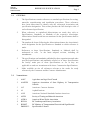
.1
The Specifications contain references to standard specifications for testing,
materials, manufacturing and installation procedures. These references
have been abbreviated to identify only the referenced Association and
specification designation. This section provides the full descriptive title of
each referenced specification.
.2
When references to capitalized abbreviations are made, they refer to
Specifications, Standards, or Methods of the respective Association.
Abbreviations listed herein but not mentioned in the specifications shall be
disregarded.
.3
The numbers & letters following the abbreviations denote the Association's
serial designation for the Specification or Standard to which reference is
made.
.4
References to these Specifications, Standards or Methods shall be
understood to refer
to the latest adopted revision, including all
amendments.
.5
The specifications and standards published by these organizations and other
specified specifications and standards referred to in these Specifications
are hereby made part of these Specifications as far as they are
applicable to and not inconsistent with these Construction Specifications.
.6
Make available on site all references relevant to the works for ready
reference by the Contractor and the Contract Administrator.
Nomenclature
.1
AAFC
Agriculture and Agri-Food Canada
.2
AASHTO
American Association of State Highway & Transportation
Officials
.3
ACI
American Concrete Institute
.4
AI
Asphalt Institute
.5
ANSI
American National Standards Institute American
.6
ASTM
Society of Testing and Materials American
.7
AWWA
American Water Works Association
.8
BCLNA
BC Landscape and Nursery Association
.9
BCMOT
E&SMS V1
BC Ministry of Transportation Electrical and Sign Material
Specification Volume 1
. MASTER MUNICIPAL SPECIFICATIONS 3.2
REFERENCE SPECIFICATIONS
Section 02000
Page 2
.10
.11
BCH
CAN
British Columbia Ministry of Transportation and Highways
Prefix signifying endorsement of other current standard as a
Canadian National Standard
.12
CCIL
Canadian Council of Independent Laboratories
.13
CCTV
Closed Circuit Television
.14
CEC
Canadian Electrical Code
.15
CGSB
Canadian General Standards Board
.16
CSA
Canadian Standards Association
.17
C-SHRP
Canadian Strategic Highway Research Program
.18
IMSA
International Municipal Signal Association
.19
JPEG
Joint Photographic Experts Group
.20
LCD
Liquid Crystal Display
.21
LED
Light Emitting Diodes
.22
MPEG-2
Moving Picture Experts Group standard for transmitting digital
video and sound in compressed format
.23
MSCC
Manual of Sewer Condition Classification – Third Edition 1993
including Addendum – February 1996
.24
MUTCDC
Manual of Uniform Traffic Control Devices of Canada
.25
NAAPI
North American Association of Pipeline Inspectors
.26
NACE
National Association of Corrosion Engineers
.27
NASCO
National Association of Sewer Service Companies
.28
NCHRP
National Cooperative Highway Research Program
.29
NEMA
National Electrical Manufacturer’s Associations
.30
WRc
Water Research Centre
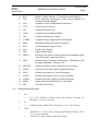
Referenced Specifications
.1
ACI
.1
.2
AI
.1
.3
ACI 315R, Manual of Engineering and Placing Drawings for
Reinforced Concrete Structure
Asphalt Institute Manual SP-2 Superpave Level 1 Mix Design
ANSI
.1
.2
ANSI B16. 1, Cast Iron Pipe Flanges and Flanged Fittings, Class
25, 125, 250,and 800
ANSI B16.5, Pipe Flanges and Pipe Fittings.
. MASTER MUNICIPAL SPECIFICATIONS .4
.5
REFERENCE SPECIFICATIONS
Section 02000
Page 3
ANSI/ACI
.1
ANSI/ACI 117, Tolerances for Concrete Construction and
Materials .
.2
ANSI/ACI 315, Details and Detailing of Concrete Reinforcement.
ANSI/AWWA
.1
ANSI/AWWA B300, Hypochlorites.
.2
.3
ANSI/AWWA B301, Water Treatment- Liquid Chlorine.
ANSI/AWWA C104/A21.4, Cement-Mortar Lining for DuctileIron Pipe and Fittings for Water.
ANSI/AWWA C105/A21.5, Polyethylene encasement for
Ductile-Iron Piping for Water and Other Liquids.
ANSI/AWWA C110/A21.10, Ductile-Iron and Gray Iron Fittings,
3 inches through 48 inches for Water and Other Liquids.
ANSI/AWWA C111/A21.11, Rubber Gasket Joints for DuctileIron and Gray Iron Pressure Pipe and Fittings.
ANSI/AWWA C150, Thickness Design of Ductile-Iron Pipe.
ANSI/AWWA C151/A21.51, Ductile-Iron Pipe, Centrifugally
Cast in Metal Molds or Sand Lined Molds for Water or other
Liquids.
ANSI/AWWA C153/A21.53, Ductile-Iron Compact Fittings, 3
inches through 16 inches, for Water and Other Liquids.
ANSI/AWWA C200, Water Pipe 6 inches and Larger, Steel.
ANSI/AWWA C203, Coal Tar Protective Coatings and Linings for
Steel Water Pipelines - Enamel and Tape - Hot Applied .
ANSI/AWWA C205, Cement Mortar Protective Lining and
Coating for Steel Water Pipe - 4 inches and larger- Shop Applied.
ANSI/AWWA C206, Field Welding of Steel Water Pipe.
ANSI/AWWA C207, Steel Pipe Flanges for Waterworks
Service, 4 inches through 144 inches.
ANSI/AWWA C208, Fabricated Steel Water Pipe Fittings,
Dimensions for.
ANSI/AWWA C210, Liquid Epoxy Coating Systems for the Interior
and Exterior of Steel Water Pipelines.
ANSI/AWWA C213, Fusion-bonded Epoxy Coating for the Interior
and Exterior of Steel Water Pipelines
ANSI/AWWA C219, Bolted, Sleeve-type Couplings for Plain-end
Pipe
ANSI/AWWA C301, Prestressed Concrete Pressure Pipe Steel
Cylinder Type for Water and Other Liquids.
.4
.5
.6
.7
.8
.9
.10
.11
.12
.13
.14
.15
.16
.17
.18
.19
. MASTER MUNICIPAL SPECIFICATIONS REFERENCE SPECIFICATIONS
.20
.21
.22
.23
.24
.25
.26
.27
.28
.29
.30
.31
.32
.33
.34
.35
.36
.37
.38
.39
.40
.41
.42
.43
Section 02000
Page 4
ANSI/AWWA C303, Reinforced Concrete Pressure Pipe Steel
Cylinder Type, Pretensioned for Water and Other Liquids.
ANSI/AWWA C500, Gate Valves for Water and Sewage Systems.
ANSI/AWWA C502, Dry-Barrel Fire Hydrants.
ANSI/AWWA C504, Butterfly Valves.
ANSI/AWWA C508, Swing-check Valves for Waterworks Service,
2in (50mm) through 24in (600mm) NPS.
ANSI/AWWA C509, Resilient-Seated Gate Valves for Water and
Sewerage Systems.
ANSI/AWWA C510, Double Check Valve Backflow-Prevention
Assembly
ANSI/AWWA C511, Reduced-pressure Principle Backflowprevention Assembly.
ANSI/AWWA C512, Air Release Air/Vacuum and Combination Air
Valves for Waterworks Service.
ANSI/AWWA C550, Protective Epoxy Interior Coating for Valves
and Hydrants.
ANSI/AWWA C600, Installation of Ductile-Iron Water Mains,
and their Appurtenances .
ANSI/AWWA C602, Cement Mortar Lining of Water Pipelines 100 mm and larger - In Place.
ANSI/AWWA C605, Underground installation of Polyvinyl Chloride
(PVC) pressure Pipe and Fittings for water.
ANSI/AWWA C651, Disinfecting Watermains.
ANSI/AWWA C800, Underground Service Line Valves and Fittings.
ANSI/AWWA C900, Pressure Pipe, 4 inches through 12 inches
for Water, Polyvinyl Chloride (PVC).
ANSI/AWWA C901, Polyethylene (PE) Pressure Pipe and
Tubing, 1/2 inch through 3 inches for Water Service.
ANSI/AWWA C902, Polybutylene (PB) Pressure Pipe and
Tubing, ½ inch through 3 inches for Water Service.
ANSI/AWWA C905, Pressure pipe and fittings, 4 inches through 63
inches for Water Distribution
ANSI/AWWA C906, Polyethylene (PE) Pressure Pipe and Fittings, 4
inches through 63 inches, for Water Distribution.
ANSI/AWWA C907, Standard for Polyvinyl Chloride (PVC)
Pressure Fittings for Water - 4 inches through 8 inches.
ANSI/AWWA M17, Installation, Field Testing, and Maintenance of
Fire Hydrants.
ANSI/AWWA M23, PVC Pipe- Design and Installation.
ANSI/AWWA M41, Ductile-Iron Pipe and Fittings.
. MASTER MUNICIPAL SPECIFICATIONS .6
.7
REFERENCE SPECIFICATIONS
Section 02000
Page 5
ASTM (A)
.1
ASTM A36, Standard Specification for Structural Steel.
.2
ASTM A48, Specification for Gray Iron Castings.
.3
ASTM A53, Specification for Pipe, Steel, Black - and Hot-Dipped,
Zinc-Coated, Welded and Seamless
.4
ASTM A90, Test Method for Weight of Coating on Zinc-Coated
(Galvanized) Iron or Steel Articles .
.5
ASTM A 120, Specification for Pipe, Steel, Black and Hot-Dipped,
Zinc-Coated (Galvanized) Welded and Seamless, for Ordinary Uses
.6
ASTM A 121, Specification for Zinc-Coated (Galvanized) Steel
Barbed Wire.
.7
ASTM A283/A283M, Specification for Low and Intermediate
Tensile Strength Carbon Steel Plates, Shapes and Bars.
.8
ASTM A307, Specification for Carbon Steel Bolts and Studs,
60,000 psi Tensile.
.9
ASTM A325, Standard Specification for High-Strength Bolts
for Structural Steel Joints.
.10
ASTM A354, Quenched and Tempered Alloy Steel Bolts, Studs and
Other Externally Threaded Fasteners.
.11
ASTM A536, Ductile Iron Castings.
.12
ASTM A585, Specification for Aluminum-Coated Steel Barbed
Wire.
.13
ASTM A563, Carbon and Alloy Steel Nuts.
.14
ASTM A615M, Deformed and Plain Billet-Steel Bars for Concrete
Reinforcement.
.15
ASTM A653/A653M, Standard Specification for Steel Sheet, Zinc
Coated (Galvanized) or Zinc-Iron Alloy-Coated (Galv-annealed) by
the Hot-Dip Process
.16
ASTM A716, Specification for Ductile -Iron Culvert Pipe.
.17
ASTM A746, Specification for Ductile -Iron Gravity Sewer Pipe.
.18
ASTM A760, Corrugated Steel Pipe, Metallic-coated for Sewers and
Drain.
.19
ASTM A 775/A 175M, Specification for Epoxy-Coated Reinforcing
Steel Bars.
ASTM (B)
.1
ASTM B62, Specification for Composition Bronze or Ounce Metal
. MASTER MUNICIPAL SPECIFICATIONS REFERENCE SPECIFICATIONS
Section 02000
Page 6
Castings.
.8
.2
ASTM B88M, Specification for Seamless Copper Water Tube.
.3
ASTM B221M, Specifications for Aluminium and
Aluminium-Alloy Extruded Bars, Rods, Wire, Shapes, and
Tubes.
.4
ASTM B633, Electro-deposited Coatings of Zinc on Iron and
Steel.
.5
ASTM B766, Electro-deposited Coatings of Cadmium.
ASTM (C)
.1
ASTM C14M, Specification for Concrete Sewer, Storm Drain,
and Culvert Pipe.
.2
ASTM C76M, Specification for Reinforced Concrete Culvert,
Storm Drain, and Sewer Pipe.
.3
ASTM C88, Test Method for Soundness of Aggregates by
Use of Sodium Sulphate or Magnesium Sulphate.
.4
ASTM C109, Test Method for Compressive Strength of
Hydraulic Cement Mortars {Using 2 inches of 50 mm Cube
Specimens).
.5
ASTM C117, Test Method for Material Finer than 0.075 mm
Sieve in Mineral Aggregate .
.6
ASTM C123, Test Method for Lightweight Pieces in Aggregate
.7
ASTM C127, Test Method for Specific Gravity and
Absorption of Coarse Aggregate.
.8
ASTM ·C-128, Test -Method for Specific Gravity and
Absorption of Fine Aggregate .
.9
ASTM C131, Test Method for Resistance to Degradation of Small
Size Course Aggregate by Abrasion and Impact in the Los Angeles
Machine.
.10
ASTM C136, Method for Sieve Analysis of Fine and Coarse
Aggregates .
.11
ASTM C139, Specification for Concrete Masonry Units for
Construction of Catchbasins and Manholes.
.12
ASTM C 171, Specification for Sheet Materials for Curing
. MASTER MUNICIPAL SPECIFICATIONS REFERENCE SPECIFICATIONS
Section 02000
Page 7
Concrete.
.9
.13
ASTM C309, Specification for Liquid Membrane-Forming
Compounds for Curing Concrete.
.14
ASTM C332, Specification for Lightweight Aggregates for
Insulating Concrete.
.15
ASTM C443M, Specification for Joints for Circular Concrete
Sewer and Culvert Pipe, Using Rubber Gaskets.
.16
ASTM C478M, Specification for Precast Reinforced Concrete
Manhole Sections.
.17
ASTM C497, Test Method for Concrete Pipe, Manhole Sections or
Tile
.18
ASTM C506M, Specification for Reinforced Concrete Arch
Culvert, Storm Drain, and Sewer Pipe.
.19
ASTM 507M, Specification for Reinforced Concrete Elliptical
Culvert, Storm Drain and Sewer Pipe.
.20
ASTM C827, Test Method for Early Volume Change of
Cementitious Mixtures.
.21
ASTM C902, Specification for Pedestrian and Light Traffic
Paving Brick.
.22
ASTM C939, Test Method for Flow of Grout for
Prep/aced-Aggregate Concrete.
.23
ASTM C1433, Precast Reinforced Concrete Box Sections for
Culverts, Storm Drains and Sewers.
.24
ASTM C1103, Joint Acceptance Testing of Installed Precast
Concrete Pipe Sewer Lines.
ASTM (D)
.1
ASTM D36, Test Method for Softening Point of Bitumen (Ring & Ball
Apparatus).
.2
ASTM D 140, Method for Sampling Bituminous Materials.
.3
ASTM D142, Test Method for Rubber Properties in Tension.
.4
ASTM D570, Test Method for Water Absorption of Plastics.
.5
ASTM D624-86, Test Method for Rubber Property- Tear
. MASTER MUNICIPAL SPECIFICATIONS REFERENCE SPECIFICATIONS
Section 02000
Page 8
Resistance.
.6
ASTM D624-86, Test Method for Rubber Property -Tear Resistance.
.7
ASTM D698, Test methods for Moisture Density Relations of Soils
and Soil Aggregate Mixtures Using 2.49 kg Rammer and 304.8 mm
Drop.
.8
ASTM D790, Standard Test Methods for Flexural Properties of
Unreinforced and Reinforced Plastics and Electrical Insulating Material.
.9
ASTM D995, Specification for Requirements for Mixing Plants
for Hot-Mixed, Hot-Laid Bituminous Paving Mixtures.
.10
ASTM D1190, Concrete Joint Sealer, Hot-Applied Elastic Type.
.11
ASTM D1248, Specification .for Polyethylene Plastics Molding
and Extrusion Materials .
.12
ASTM D 1557, Specification for Test Methods for MoistureDensity Relations of Soils and Soil-Aggregate Mixtures using 10
lb (4.54 kg) Rammer and 18 inch (457 mm) Drop.
.13
ASTM D1559, Test Method Resistance to Plastic flow of
Bituminous Mixtures Using Marshall Apparatus.
.14
ASTM D1751, Specification for Preformed Expansion Joint Fillers
for Concrete Paving and Structural Construction (Non-extruding and
Resilient Bituminous Types).
.15
ASTM D1752, Specification for Preformed Sponge Rubber and
Cork Expansion Joint Fillers for Concrete Paving and Structural
Construction.
.16
ASTM D1784, Standard Specification for Rigid Polyvinyl Chloride
(PVC) Compounds and Chlorinated Polyvinyl Chloride (CPVC)
Compounds.
.17
ASTM D 1862, Test Methods for Breaking Load and Elongation
Textile Fabric.
.18
ASTM D2000, Classification System for Rubber Products in
Automotive Applications.
.19
ASTM D2152, Test Method for Quality of Extruded Polyvinyl
Chloride (PVC) Pipe by Acetone Immersion.
.20
ASTM D2241, Standard Specification for Polyvinyl Chloride (PVC)
Plastic Pipe (SDR-PR).
.21
ASTM D2310, Classification for Machine Made Reinforced
Thermosetting Resin Pipe.
.22
ASTM D2321-05, Standard Practice for Underground Installation of
. MASTER MUNICIPAL SPECIFICATIONS REFERENCE SPECIFICATIONS
Section 02000
Page 9
Thermoplastic Pipe for Sewers and Other Gravity-flow Applications.
.23
ASTM D2412, Standard Test Method for External Loading
Properties of Plastic Pipe by Parallel - Plate Loading.
.24
ASTM D2419, Test Method for Sand Equivalent Value of Soils
and Fine Aggregate .
.25
ASTM D 2 6 5 7 , S t a n d a r d Practices for Heat Fusion Joining
Polyethylene Pipe and Fittings.
.26
ASTM D2680, Specification for Acrylonitrile-Butadiene-Styrene
(ABS) and Poly (Vinyl Chloride) (PVC) Composite Sewer Piping.
.27
ASTM D 2 7 7 4 , Practices for Underground, Installation of
Thermoplastic Pressure Piping.
.28
ASTM D2837, Method for Obtaining Hydrostatic Design Basis for
Thermoplastic Pipe Materials.
.29
ASTM D2990, Standard Test Method for Tensile, Compressive, and
Flexural Creep and Creep-Rupture of Plastics.
.30
ASTM D2992, Method for Obtaining Hydrostatic Design Basis
for Reinforced Thermosetting Resin Pipe and Fittings.
.31
ASTM D2996, Specification for Filament Wound Reinforced
Thermosetting Resin Pipe.
.32
ASTM D3034, Specification for Type PSM Poly (Vinyl Chloride)
(PVC) Sewer Pipe and Fittings.
.33
ASTM D3035-08, Standard Specification for Polyethylene (PE)
Plastic Pipe (DR-PR). Based on controlled outside diameter.
.34
ASTM D3139, Joints for Plastic Pressure Pipes using Flexible
Elastomeric Seals.
.35
ASTM D3203, Test Method for Percent Air Voids in Compacted
Dense and Open Bituminous Paving Mixtures.
.36
ASTM D3210, Classification for Machine Made Reinforced
Thermosetting Resin Pipe
.37
ASTM D3212, Specifications for Joints for Drain and Sewer Plastic
Pipes using Flexible Elastomeric Seals.
.38
ASTM D3261, Standard Specification for Butt Heat Fusion
Polyethylene (PE) Plastic Fittings for Polyethylene (PE) Plastic Pipe
and Tubing..
.39
ASTM D3350, Specification for Polyethylene Plastic Pipe and
Fittings Materials
.40
ASTM D3405, Specification for Joint Sealants, Hot Poured for
. MASTER MUNICIPAL SPECIFICATIONS REFERENCE SPECIFICATIONS
Section 02000
Page 10
Concrete and Asphalt Pavements.
.10
.11
.41
ASTM D4101, Propylene Plastic Injection and Extrusion Materials.
.42
ASTM D4318, Test Method for Liquid Limit, Plastic Limit, and
Plasticity Index of Soils.
.43
ASTM D4354, Practice for Sampling of Geo-synthetics for Testing.
.44
ASTM D4541, Standard Test Method for Pull-Off Strength of
Coatings Using Portable Adhesion Testers.
.45
ASTM D4956, Standard Specification for Retro-reflective Sheeting
for Traffic Control.
.46
ASTM D5813, Standard Specification for Cured-in-Place
Thermosetting Resin Sewer Piping Systems.
ASTM (E)
.1
ASTM E11, Specification for Wire Cloth Sieves for Testing
Purposes.
.2
ASTM E1155M, Test Method for Determining Floor Flatness
and Levelness Using the F-Number System.
.3
ASTM E1252, Standard Practice for General Techniques for
Obtaining Infrared Spectra for Qualitative Analysis.
ASTM (F)
.1
.2
.3
.4
.5
.6
ASTM F436, Hardened Steel Washers.
ASTM F477, Specification for Elastomeric Seals (Gaskets) for
Joining Plastic Pipe.
ASTM F593, Stainless Steel Bolts, Hex Cap Screws and Studs.
ASTM F594, Stainless Steel Nuts.
ASTM F679, Specification for Type PSM Polyvinyl Chloride
(PVC) Sewer Pipe and Fittings.
ASTM F714, Polyethylene (PE) Plastic Pipe (SDR-DR) Based
on Outside Diameter .
.7
ASTM F738, Stainless Steel Metric Bolts, Screws, and Studs.
.8
ASTM F794, Specification for Polyvinyl Chloride (PVC) Ribbed
Gravity Sewer Pipe and Fittings based on Controlled Inside Diameter.
.9
ASTM F836M, Style 1 Stainless Steel Metric Nuts.
. MASTER MUNICIPAL SPECIFICATIONS REFERENCE SPECIFICATIONS
Section 02000
Page 11
.10
ASTM F1055, Standard Specification for Electro-fusion Type
Polyethylene Fittings for Outside Diameter Controlled Polyethylene
Pipe and Tubing.
.11
ASTM F1216, Standard Practice for Rehabilitation of Existing
Pipelines and Conduits by the Inversion and Curing of a ResinImpregnated Tube.
.12
ASTM F1743, Standard Practice for the Rehabilitation of Existing
Pipelines and Conduits by the Pulled in Place Installation of Cured-inPlace Thermosetting Resin Pipe (CIPP).
.13
ASTM F2019, Standard Practice for the Rehabilitation of Existing
Pipelines and Conduits by the Pulled in Place Installation of Glass
Reinforced Plastic (GRP) Cured-in-Place Thermosetting Resin Pipe
(CIPP).
.12
AWWA: (See ANSI /AWWA)
.13
BCLNA
BC Landscape Standard 2008 (7th Ed)
Canadian Standard for Nursery Stock – (8th Ed)
Canadian System of Soil Classification – (3rd Ed)
.14
.15
CAN3 = CAN/CSA
.1
CAN3-A 165 Series, CSA Standards on Concrete Masonry Units.
.2
CAN3-B137.3, Rigid Poly (Vinyl Chloride) (PVC) Pipe for Pressure
Applications .
.3
CAN4-S543, Internal Lug, Quick-Connect Couplings for Fire Hose.
.4
CAN3-B70, Cast Iron Soil Pipe and Fittings, and Means of Joining.
.5
CAN3-G401, Corrugated Steel Pipe Products.
.6
CAN3-A23.3, Design of Concrete Structures for Buildings .
CAN/CSA = CAN3
.1
CSA A3000, Portland Cement; Masonry Cement, Blending Hydraulic
Cement, Cementitious Hydraulic Slag.
.2
CAN/CSA-A5, Portland Cement.
.3
CAN/CSA-A8, Masonry Cement.
.4
CAN3-A23.1, Concrete Materials and Methods for Concrete
Construction.
.5
CAN/CSA-A23.2, Methods of Testing for Concrete.
. MASTER MUNICIPAL SPECIFICATIONS .16
.17
REFERENCE SPECIFICATIONS
Section 02000
Page 12
.6
CAN/CSA-A23.5, Supplementary Cementing Materials.
.7
CAN3-A231.2, Precast Concrete Pavers.
.8
CAN3-A266. 1, Air-Entraining Admixtures for Concrete.
.9
CAN3-A266.2, Chemical Admixtures for Concrete.
.10
CAN3-A266.4, Guidelines for the use of Admixtures in Concrete.
.11
CAN3-A362, Blending Hydraulic Cement.
.12
CAN/CSA-A363, Cementitious Hydraulic Slag.
.13
CAN/CSA-B182.1, Plastic Drain and Sewer Pipe and Pipe Fittings.
.14
CAN/CSA-B182.6M, Profile of Polyolefin Sewer Pipe and Pipe Fittings.
.15
CAN/CSA-G40.21, Structural Quality Steels.
CAN / CGSB
.1
CAN/CGSB-8.1, Sieves Testing, Woven Wire.
.2
CAN/CGSB-8. 2, Sieves Testing, Woven Wire, Metric.
.3
CAN/CGSB-138. 1, Fence, Chain Link, Fabric
.4
CAN/CGSB-138. 2, Fence, Chain Link, Framework, Zinc-Coated,
Steel.
.5
CAN/CGSB-138.3, Fence Chain Link -Installation.
.6
CAN/CGSB-138.4, Fence, Chain Link, Gates.
.7
CAN/CGSB-37.2, Emulsified Asphalt, Mineral Colloid-Type,
Unfilled, for Damp-proofing and Waterproofing and for Roof
Coatings.
.8
CAN/CGSB-16. 1, Asphalts, Liquids Petroleum, for Road Purposes
.9
CAN/CGSB-16. 2, Asphalts, Emulsified, Anionic Type, for Road
Purposes.
.10
CAN/CGSB-16. 3, Asphalt Cements for Road Purposes .
.11
CAN/CGSB-16. 5, Asphalt, Emulsified, High Float Type, for Road
Purposes.
CGSB
.1
CGSB 1-GP-12c, Standard Paint Colours.
.2
CGSB 1-GP-59M, Enamel, Exterior Gloss Alkyd Type.
.3
CGSB 1-GP-5M, Thinner, Petroleum Spirits, Low Flash {R/84).
.4
CGSB 1-GP-71, Method of Testing Paints and Pigments.
. MASTER MUNICIPAL SPECIFICATIONS .18
REFERENCE SPECIFICATIONS
Section 02000
Page 13
.5
CGSB 1-GP-74M, Paint, Traffic, Alkyd.
.6
CGSB 1-GP-149M, Paint, Traffic, Reflectorized Alkyd, White and
Yellow.
.7
CGSB 15.1-92, Standard for Calcium Chloride.
.8
CGSB 1-GP-181M, Coating, Zinc-Rich, Organic, Ready Mixed.
.9
CGSB 51-GP-51M, Polyethylene Sheet for Using in Building
Construction.
.10
CGSB 41-GP-25M, Pipe, Polyethylene, for the Transport of Liquids.
CSA
.1
CSA 283, Qualification Code for Concrete Testing Laboratories.
.2
CSA A14, Concrete Poles.
.3
CSA A82. 5, Structural Clay Non-Load-Bearing Tile.
.4
CSA A82. 56, Aggregate for Masonry Mortar.
.5
CSA A 123.3, Asphalt or Tar Roofing Sheets.
.6
CSA A257, Standards for Concrete Pipe and Manholes (AS257.0
through AS257.4).
.7
CSA B137.0, Definitions, General Requirements, and Methods of
Testing for Thermoplastic Piping.
.8
CSA B137.1, Polyethylene Pipe, Tubing and Fittings for Cold
Water Pressure Services.
.9
CSA B137.2, PVC Injection Moulded Gasketed Fittings for pressure
Applications.
.10
CSA B137.3, Rigid Poly (Vinyl Chloride} (PVC} Pipe for Pressure
Applications.
.11
CSA B137.6, CPVC Pipe, Tubing and Fittings for Hot and Cold Water
Distribution Systems.
.12
CSA B137.7, Polybutylene (PB) Pipe for Cold Water Distribution
systems.
.13
CSA B137.8, Polybutylene (PB) Pipe for Pressure Applications.
.14
CSA B137.9(M91), Polyethylene, Aluminium, Polyethylene Composite
Pressure Pipe.
.15
CSA B137.16, Recommended Practice for the Installation of CPVC
Piping for Hot and Cold Water Distribution Systems.
.16
CSA 182.1, Plastic Drain and Sewer Pipe and Pipe Fittings.
. MASTER MUNICIPAL SPECIFICATIONS REFERENCE SPECIFICATIONS
Section 02000
Page 14
.17
CSA B 182.11, Recommended Practice for the Installation of Plastic
Drain and Sewer Pipe and pipe Fittings
.18
CSA B181.12, Recommended Practice for the Installation of
PVC Drain, Waste, and Vent Pipe Fittings.
.19
CSA B 182.11, Recommended Practice for the Installation of Plastic
Drain and Sewer Pipe and pipe Fittings.
.20
CSA B182.2, Large Diameter, Type PSM PVC Sewer Pipe and
Fittings.
.21
CSA B182.4, Large Diameter Ribbed PVC Sewer Pipe and Fittings.
.22
CSA C22.1, Safety Standard for Electrical Installations.
.23
CSA C22.2, Canadian Electrical Code, General Requirements.
No. 03
No. 18.1
No. 18.4
No. 29
No. 38
No. 42
No. 45
No. 49
No. 56
No. 85
No. 89
Test Methods for Electrical Wires and Cables
Metallic Outlet Boxes
Hardware for the Support of Conduit, Tubing and Cable
Panelboards and Enclosed Panelboards
Thermoset Insulated Wires and Cables
General Use Receptacles, Attachment Plus and Similar
Wiring Devices Rigid
Metal Conduit
Flexible Cord and Cables
Flexible Metal conduit and Liquid Tight Flexible Metal
Conduit
Rigid PVC Boxes and Fittings
Splitters
.24
CSA C22.3, Canadian Electrical Code Outside Wiring.
.25
CSA G30.3, Cold Drawn Steel Wire for Concrete Reinforcement.
.26
CSA G30.5, Welded Steel Wire Fabric for Concrete Reinforcement.
.27
CSA 30.12 - M77, Billet-Steel Bars for Concrete Reinforcement.
.28
CSA G30. 14, Deformed Steel Wire for Concrete Reinforcement.
.29
CSA G30. 15, Welded Deformed Steel Wire Fabric for Concrete
Reinforcement.
.30
CSA G30.16, Weldable Low Alloy Steel Deformed Bars for
Concrete Reinforcement.
.31
CSA G 164, Hot Dip Galvanizing of Irregularly Shaped Articles.
.32
CSA S 157, Strength Design in Aluminum.
. MASTER MUNICIPAL SPECIFICATIONS .19
REFERENCE SPECIFICATIONS
Section 02000
Page 15
.33
CSA S269.3, Formwork
.34
CSA W59, Welded Steel Construction (Metal Arc Welding).
.35
CSA W186, Welding of Reinforcing Bars in Reinforced Concrete
Construction.
.36
CSA G40.20, General Requirements for Rolled or Welded Structural
Quality Steel / Structural Quality Steels.
C-SHRP
1. Superpave Series No.2 (SP-2) Superpave level 1 Mix Design
2. Technical Brief #17, Superpave 2000 -Improved Standards for a
new Millennium.
.20
IMSA
1. 50-2, Polyethylene insulated, polyethylene jacketed, loop detector
lead-in cable.
.21
NEMA
1. TS 2-2003(R2008), Traffic Controller Assemblies with NTCIP
Requirements, Version 02.60.
2. 250-2003, Enclosures for Electrical Equipment (1,000 Volts Max).
.22
BCH
1.
2.
3.
4.
.23
BCH 1-9, Degradation Test
BCH 1-13, Fracture Count on Coarse Aggregates
Electrical and Signing Material Standards.
Specifications for Standard Highway Sign Materials, Fabrication
and Supply.
Plastic Pipe Institute Handbook on Polyethylene Pipe
END OF SECTION
MASTER
MUNICIPAL
SPECIFICATIONS
1.0
GENERAL
MEASUREMENT
& PAYMENT
SECTION 02100
PAGE 1
.1 Section 02100 addresses general requirements for
measurement and payment for all items under the
Schedule of quantities and Prices.
.2 If a separate item is not provided for in the Schedule of
Quantities and Prices but is indicated in the specifications
or on the drawings as being part of the work, e.g.
reinstatement, then provide for it in the rates generally.
.3 If an “allowance” is provided for in the Schedule of
Quantities and Prices, it shall take the same general
meaning as Contingency Allowance as defined in the
General Conditions of Contract.
1.1 Measurement and
Payment
.1 Units of measurement for payment will be as indicated in
the Schedule of Quantities and Prices. Payments will be
based on respective unit or lump sum prices in the
Schedule of Quantities and Prices or in Change Orders if
issued.
.2 Unless specified otherwise, the standard methods of
measurement will be as follows:
Linear measurement will be measured in place taken
from end to end along the length of the measured item.
Area measurement will be calculated from
conventionally accepted geometric area formulae using
linear measurements taken in place of the completed
area of work or, alternatively, by using GPS coordinates taken on site of the boundary of the area of
the work completed and inputted into an acceptable
software model such as Civil 3D, the method being
agreed to prior to commencement of the work.
Cubic measurement will be made in place, all as
specified under individual payment sub-sections, using
one of the following methods:
3 dimensional software modelling techniques (Civil
3D or equal) using data derived from field surveys
completed before and after the work but only to the
limits shown on the drawings or as agreed
end area method at 15m sections (unless agreed
differently) using data derived from field surveys
MASTER
MUNICIPAL
SPECIFICATIONS
MEASUREMENT
& PAYMENT
SECTION 02100
PAGE 2
completed before and after the work but only to the
limits shown on the drawings or as agreed
rocks or boulders greater than 0.5 m3 in volume,
measured in the shortest direction in the x, y and z
planes and by multiplying the three values together
for each rock or boulder > 0.5 m3 in volume.
loose truck box volume by truck count, which
volume shall be agreed in advance.
Weight measurement for materials delivered in
truckloads will be made by weigh tickets displaying the
truck weight before and after loading, to be verified in
accordance with the Force Account procedure.
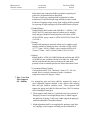
.3 Unless otherwise specified, accuracy of measurement will
be to the nearest significant decimal value as given
below:
Asphalt
Concrete
Excavation, earth, and
granular materials
Pipes
All unit items
Clearing, grubbing, top soil, seeding,
sodding area
Asphalt or concrete area
Lump sum for provide, maintain
1.2
0.1 tonne
0.01 cubic metre
0.1 tonne or cubic metre
0.1 metre
each
1.0 metre squared (m2)
Length to 0.1 metre by
specified Width to 0.1
metre
To be specified
Payment Inclusions .1 Payment for items under Schedule of Quantities and
Prices includes the supply and installation of work
described under the items and referenced in the
Measurement and Payment clauses in the Supplemental
General Conditions, including all necessary materials,
equipment and labour, cut and waste, working clearance,
specified testing for the finished items of work, other
incidental and miscellaneous materials, fitting,
appurtenances and work and requirements under Division
I and as specified under respective Sections of Master
Municipal Specifications and under Instructions to
Tenderers, paragraph 10.1.
.2 Unless provided for otherwise, the costs of bonds,
insurance, Workers Compensation contribution,
MASTER
MUNICIPAL
SPECIFICATIONS
MEASUREMENT
& PAYMENT
SECTION 02100
PAGE 3
superintendence, overheads, profits, and other incidentals,
where not identified separately, are deemed to have been
included in the pay items of the Schedule of Quantities
and Prices generally.
.3 Payment will not be made for unauthorized work nor
work beyond limits shown on Contract Drawings.
1.3
Description of Pay Items
.1 The completion of individual items of work under the
Contract shall be measured and paid for in accordance
with the Description of Pay Items in Section 5 of the
Supplemental General Conditions of Contract.
1.4
Partially Completed
Work at the End of
Pay Periods
.1 Lump Sum or unit rate items which are only partially
completed at the end of pay periods will be paid for as a
percentage of the value of the work completed, in the
case of Lump Sum items or pro-rated according to the
state of the work, e.g. watermain installed and backfilled
but not yet tested or disinfected, as approved by the
Contract Administrator.
*** END SECTION 02100 ***
MASTER
MUNICIPAL
SPECIFICATIONS
CLEARING
AND
SECTION 02111
PAGE 1
GRUBBING
1.0
GENERAL
.1 Section 02111 refers to those portions of the work that
are unique to clearing and grubbing. This section must be
referenced to and interpreted simultaneously with all
other sections pertinent to the works described herein.
The contractor shall be responsible for timber permits.
1.1
Related Work
.1 Environmental Protection
Section 01561
.2 Shrub and Tree Preservation
Section 02104
.3 Site Grading
Section 02210
.4 Excavating, Trenching, and Backfilling
Section 02223
.5 Roadway Excavation, Embankment,
and Compaction
Section 02224
1.2
Definitions
.1 Clearing consists of cutting of trees, brush, and heavy
vegetative growth to not more than a specified height
above surrounding ground and disposing of felled trees,
brush, vegetative growth, including all underbrush,
deadwood, and surface debris.
.2 Close-cut clearing consists of cutting of standing trees,
brush, scrub, roots, stumps, and embedded logs,
removing flush with existing grade and disposing of
fallen timber and surface debris.
.3 Clearing isolated trees consists of cutting off to not more
than a specified height above ground designated trees and
disposing of felled trees and debris.
.4 Grubbing consists of excavation and disposal of stumps
and roots to not less than a specified depth below existing
ground surface.
1.3
Protection of
Existing Features
.1 Prevent damage to all adjacent natural growth,
landscaping, buildings, structures, and underground and
overhead utilities. Make good all damage to satisfaction
of Contract Administrator.
.2 Apply specified tree paint to cuts or scars suffered by
vegetation designated to remain.
MASTER
MUNICIPAL
SPECIFICATIONS
1.4
1.5
2.0
CLEARING
AND
SECTION 02111
PAGE 2
GRUBBING
Measurement
and Payment
.1 Refer to Section 02100, Measurement and Payment.
Inspection and
Testing
.1 Refer to General Conditions, Clause 4.12, Inspections.
PRODUCTS
NOT APPLICABLE
3.0 EXECUTION
.1 Prior to clearing, verify limits of clearing with Contract
Administrator, and determine any restriction regarding
preservation of existing tress, shrubs, natural features, or
improvements within or adjacent to specified limits of
clearing.
.2 The Contractor shall be responsible for timber permits.
3.1
Clearing
.1 Clear trees, shrubs, uprooted stumps, and surface debris
not designated to remain.
.2 Cut off trees, brush, and scrub at a height of not more
than 300mm above ground. In areas to be subsequently
grubbed, ensure height of stumps left from clearing
operations not more than 1000mm above existing ground.
.3 Upon written authorization from Contract Administrator,
cut off unsound branches of trees designated to be
preserved and fall isolated trees overhanging area to be
cleared.
.4 Preserve all shrubs, trees, or other cultivated plants
specified for replanting.
3.2
3.3
Close-Cut
Clearing
Isolated Trees
.1 Cut off trees, shrubs, stumps, and other vegetation at
ground level.
.1 Cut off isolated trees as shown on Contract Drawings or
as directed by Contract Administrator at height of not
more than 300mm above existing ground.
.2 Grub out isolated tree stumps.
MASTER
MUNICIPAL
SPECIFICATIONS
3.4
Grubbing
3.5
Removal and
Disposal
CLEARING
AND
SECTION 02111
PAGE 3
GRUBBING
.1 Grub out stumps and roots in cleared areas to not less
than 200mm below existing ground surface.
.1 Unless specified otherwise in Supplementary
Specifications all timber becomes property of Contractor.
.2 Off-site disposal of cleared and grubbed materials will
not be required.
.3 Cleared and grubbed waste materials are intended to be
disposed of on-site via burning of slash piles. The
Contractor is responsible for burning of rubbish, fire
control, and burning permits.
.4 Where specified, chip or mulch and spread cleared and
grubbed vegetative material on site.
3.6
`
Finished Surface
.1 Leave ground surface in condition suitable for immediate
grading operations or stripping of topsoil if so specified.
MASTER
MUNICIPAL
SPECIFICATIONS
1.0 General
LANDSCAPING
GRADING
SECTION 02211
PAGE 1
.1 Section 02211 refers to those portions of the work for
preparation of subgrade by grading and filling, to provide
a base that will allow placing of growing medium
(topsoil) to specified depths. This section must be
referenced to and interpreted simultaneously with all
other sections pertinent to the works described herein.
.2 This section is based on the “British Columbia Landscape
Standard” published by the B.C. Society of Landscape
Architects and the B.C. Nursery Trades Association. This
standard is intended to set a level of quality which is to be
equalled or bettered in the construction documents for
each project. Guidance of a registered British Columbia
Landscape Architect is recommended.
.3 This section is included for reinstatement work.
1.1
1.2
Related Work
References
.1 Topsoil and Finish Grading
Section 02921
.2 Seeding
Section 02933
.3 Hydraulic Seeding
Section 02934
.4 Sodding
Section 02938
.5 Planting of Trees, Shrubs
and Ground Covers
Section 02950
.1 British Columbia Landscape Standard.
.2 Canadian System of soil classification
1.3
Site Conditions
.1 Examine site with Contract Administrator and obtain
approval of previous work prior to commencing site
grading.
.2 Comply with General Conditions, Clause 4.3, Protections
of Work, Property and the Public, and Clause 4.5, Errors,
Inconsistencies or Omissions in the Contract Documents.
1.4
Measurement
and Payment
.1 If a separate Landscape Grading Item is not included in
the schedule of rates e.g. reinstatement, then it shall be
provided for in the rates generally.
MASTER
MUNICIPAL
SPECIFICATIONS
LANDSCAPING
GRADING
SECTION 02211
PAGE 2
.2 Refer to Section 02100, Measurement and Payment,
Subsection 1.2, Description of Pay Items.
1.5
Inspection and
Testing
.1 Refer to General Conditions, Clause 4.12, Inspections.
2.0 PRODUCTS
2.1 Materials
.1 Fill Materials: In case of deficit of in-place or specified
materials, all additional materials necessary to bring site
up to specified grade to comply with material specified in
appropriate Section or shown on Contract Drawings.
.2 Obtain approval from Contract Administrator for
excavated or graded material to be used as fill for grading
work. Protect approved material from contamination.
.3 Fill material to be placed under areas to be landscaped,
i.e., with grass, sod, groundcover, shrubs and tees, to be
non-toxic to plant and annual life in part or in
concentration (leachate).
3.0
EXECUTION
3.1 Stripping of Topsoil .1 Strip all organic material to specified limits and specified
limits and specified depth. Stockpile for re-use on site
during construction. Do not handle topsoil while in wet
or frozen condition or in any manner in which soil
structure is adversely affected. Remove all debris and
unusable material as specified in the Contract
Documents. Prior to construction completion, the
stockpiled topsoil materials shall be spread on-site in
such a fashion as to achieve a reasonable landscaped
finish to the site.
.2 Surface drainage: Provide suitable temporary ditches or
other approved means of handling drainage prior to
excavation and during construction to protect
construction area and adjacent and other adjacent
MASTER
MUNICIPAL
SPECIFICATIONS
LANDSCAPING
GRADING
SECTION 02211
PAGE 3
properties. Provide siltation controls to protect natural
watercourses or existing drainage facilities.
3.2
Grading
.1 Rough grade to levels, profiles, and contours allowing for
surface treatment as shown on Contract Drawings.
.2 Compact subgrade to a consistent 80% Modified Proctor
Density in compliance with ASTM D1557.
.3 Excavate soft and instable areas below subgrade that
cannot be compacted to this standard and fill with
approved fill material, except in locations where special
environmental conditions have been identified. In such
cases, comply with Supplementary Specifications and
details shown on Contract Drawings.
.4 Remove and dispose to approved off-site disposal areas,
all debris, roots, branches, stones, building material,
contaminated subsoil, visible weeds and anything else
that may interfere with proper growth and development
of planned finished landscaping.
5. Place fill materials to elevations and sections shown on
Contract Drawings. Place in maximum 200mm lifts and
compact each lift to 80% Modified Proctor Density
immediately before placing growing medium (topsoil).
.6 Scarify areas showing excessive compaction to minimum
depth of 150mm and compact to 80% Modified Proctor
Density immediately before placing growing medium
(topsoil).
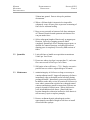
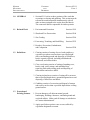
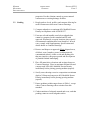
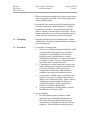
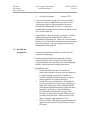
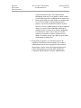
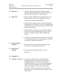
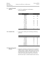
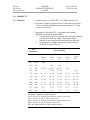
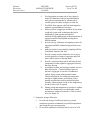
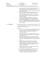
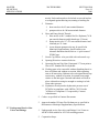
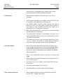
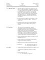
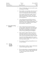
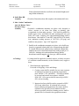
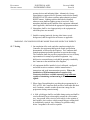
.7 Ensure gradients within ranges shown in Table 1, except
where Contract Drawings show variation from this
standard.
.8 Grade transitions of subgrade smooth and even, such that
ponding cannot occur on subgrade surface.
MASTER
MUNICIPAL
SPECIFICATIONS
SECTION 02211
PAGE 4
LANDSCAPING
GRADING
TABLE 1: Maximum and Minimum
Gradients in Landscaped Areas
Location
Lawn and Grass
Grass Swales (without additional
erosion protection)
i) Slope along inverts
ii) Slide Slopes
Unmowed Areas
Planted Areas
Minimum
Maximum
50:1 (2%)
3:01
10:1
(10%)
50:1 (2%)
6:1
(preferred)
100:1 (1%)
50:1 (2%)
3:01
2:1*
2:1*
*Unless directed otherwise by Contract Administrator
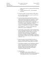
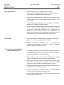
3.3
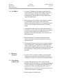
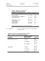
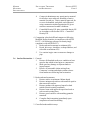
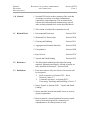
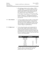
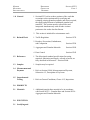
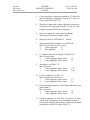
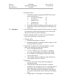
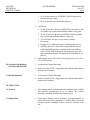
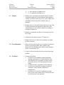
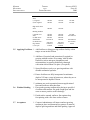
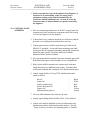
Tolerances
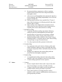
.1 Accuracy of subgrade elevations to be within tolerances
shown in Table 2.
TABLE 2: Tolerances for Subgrades Where Growing
Medium (Topsoil) to be Placed Over Subgrade
Conditions
Within 3 m from fixed elevations (e.g.
paving edges, curbs, etc.)
Intended Growing
Medium Depth
0-15 mm
151-300 mm
301 - 600 mm
Other areas
0-150 mm
151-300 mm
301-600 mm
Tolerance
(+/-)
25mm
(+/-) 25
mm
(+/-) 50
mm
(+/-) 25
mm
(+/-) 50
mm
(+/-) 50
mm)
MASTER
MUNICIPAL
SPECIFICATIONS
3.4
Surplus Material
3.5
Topsoil and Finish
Grading
LANDSCAPING
GRADING
SECTION 02211
PAGE 5
.1 Remove surplus material unsuitable for fill, grading, or
landscaping and dispose at approved disposal area.
.1 See Section 02921 – Topsoil and Finish Grading for
placement and finish grading of growing medium
(topsoil).
MASTER
MUNICIPAL
SPECIFICATIONS
EXCAVATING, TRENCHING
AND BACKFILLING
SECTION 02223
PAGE 1
1.0 General
.1 Section 02223 refers to those portions of the work that
are unique to excavating, trenching, and backfilling of
underground utility installations and related to structures.
This section must be referenced to and interpreted
simultaneously with all other sections pertinent to the
works described herein. This section shall also refer to
installation of pipe and conduit installed for
telecommunications, gas, and electrical services.
1.1
.1 Environmental Protection
Section 01561
.2 Rock Removal
Section 02221
.3 Controlled Density Fill
Section 02236
.4 Aggregates and Granular Materials
Section 02950
.5 Waterworks
Section 02666
.6 Storm Sewers
Section 02721
.7 Pipe Culverts
Section 02723
.8 Manholes and Catchbasins
Section 02725
.9 Sanitary Sewers
Section 02731
.10 Sewage Forcemains
Section 02732
.11 Topsoil and Finish Grading
Section 02921
.12 Packaged Equipment
Section 15000
Related Work
1.2
References
.1 The abbreviated standard specifications for testing,
materials, fabrication and supply, referred to herein, are
fully described in References – Section 02000.
1.3
Definitions
.1 Rock Excavation: as defined in Section 02221 – Rock
Removal.
.2 Common Excavation: excavation of materials of
whatever nature, which are not included under definitions
of rock excavation including dense tills, hardpan,
partially cemented materials, clay or frozen materials
MASTER
MUNICIPAL
SPECIFICATIONS
EXCAVATING, TRENCHING
AND BACKFILLING
SECTION 02223
PAGE 2
which can be ripped and excavated with heavy
construction equipment.
.3 Over-excavation: excavation below design elevation of
bottom of specified bedding, and including backfilling of
resultant excavation with specified material, as authorized
by Contract Administrator.
.4 Removals: removal and disposal at an approved location
off-site of surface concrete structures and walks, curbs,
gutters, manholes, catchbasins, pipes, culverts, endwalls,
and any other structures on surface or underground
specifically designated on Contract Drawings for
removal. Removals to include backfilling of resultant
excavation with specified material.
.5 Native Topsoil: to Section 02921 – Topsoil and Finish
Grading.
1.4
Protection of Work,
Property, and
Public
.1 Comply with General Conditions, Clause 4.3, Protection
of Work, Property, and the Public.
1.5 Safety
Requirements
.1 Comply with General Conditions, Clause 4.2, Safety.
.2 Design and install trench shoring in accordance with the
regulations of the Workers Compensation Act of British
Columbia.
1.6
Blasting
.1 Ensure all blasting operations comply with Section 02221
– Rock Removal
1.7
Disposal
.1 Dispose of all surplus spoil from excavation on-site
and/or off-site as shown on Contract Drawings or as
specified in Contract Documents. Suitability of
excavated material for use as native bedding or trench
backfill will be governed by Part 2 of this Section.
Dumping of spoil on private property will be permitted
only upon written approval from property owner and
provided all necessary permits and approvals have been
obtained.
MASTER
MUNICIPAL
SPECIFICATIONS
1.8 Limitations of
Open Trench
1.9
Permits and
Approvals
1.10 Measurement and
Payment
1.11 Inspection and
Testing
EXCAVATING, TRENCHING
AND BACKFILLING
SECTION 02223
PAGE 3
.1 Excavate trenches only as far in advance of pipe laying
operation as safety, traffic, and weather conditions permit
and, in no case, to exceed 30m. Before stopping work on
last day of work before each weekend or holiday,
completely backfill every trench. If circumstances do not
permit complete backfilling of all trenches, adequately
protect all open trenches or excavation with approved
fencing or barricades and, where required, with flashing
lights.
.1 Comply with General Conditions, Clause 20, Laws,
Notices, Permits, and Fees.
.1 Refer to Section 02100, Measurement and Payment,
Subsection 1.2, Description of Pay Items.
.1 Refer to General Conditions, Clause 4.12, Inspections.
2.0 PRODUCTS
2.1
General
2.2
Use of Specified
Material
.1 Unless shown otherwise on Contract Drawings the
materials specified in 2.2 following are approved for their
respective uses.
.1 Backfill for over-excavated trench or structure
excavations to be one of the following:
.1
Granular pipe bedding and surround material.
.2
Pit run sand.
.3 Drain rock (only where approved by Contract
Administrator).
.4 Concrete.
.5 Controlled density fill.
.2 Pipe bedding and surround: see applicable Sections:
.1
Waterworks
Section 02666
.2 Storm Sewers
Section 02721
.3
Pipe Culverts
Section 02723
MASTER
MUNICIPAL
SPECIFICATIONS
EXCAVATING, TRENCHING
AND BACKFILLING
.4
.5
.6
Sanitary Sewers
Sewage Forcemains
Electrical
SECTION 02223
PAGE 4
Section 02731
Section 02732
Section 16550
.3 Trench and excavation backfill to be one of the
following:
.1
Approved native material.
.2
Pit run gravel.
.3
Pit run sand.
.4 Controlled density fill.
.4 Surface treatment to be:
.1
Restoration to match existing conditions.
.2
Subgrade, subbase, and base for works describe in
other Sections.
.3
Topsoil, grass, sod, or requirements for landscaping
works described in other Sections.
2.3
Materials
.1 Refer to Section 02226 – Aggregates and Granular
Materials for specifications for approved granular
materials and approved native material.
.2 Other granular materials: granular materials approved for
roadwork (subbase, base) also acceptable for trench
backfill subject to approval of Contract Administrator.
.3 Concrete: to Section 03300, to be minimum 20MPa.
.4 Controlled Density Fill: to Section 02236, to be
maximum 0.5MPa.
3.0 EXECUTION
3.1
Site Preparation
.1 Remove all brush, weeds, grasses, and accumulated
debris to an approved offsite location.
.2 Cut pavement or sidewalk neatly along limits of proposed
excavation as shown on Standard Detail Drawing G4 in
order that surface may break evenly and cleanly. Cut
beyond limits shown only if authorized by Contract
Administrator.
MASTER
MUNICIPAL
SPECIFICATIONS
EXCAVATING, TRENCHING
AND BACKFILLING
SECTION 02223
PAGE 5
.3 Where trench passes through lawn, neatly cut and remove
sod before trench excavation. Save sod for replacement
upon backfilling trench.
.4 Strip topsoil after area has been cleared and stockpile in
locations as shown on Contract Drawings. Stockpile
height not to exceed 2m. Avoid mixing topsoil with
subsoil. Dispose of unused topsoil as specified. Do not
handle topsoil while in wet or frozen condition or in any
manner in which soil structure is adversely affected.
3.2
Stockpiling
.1 Stockpile fill materials in areas designated by Contract
Administrator. Stockpile granular materials in manner to
prevent segregation.
3.3
Excavation
.1 Connection to existing mains:
.1
Prior to or at commencement of construction, check
existing main for line and elevation at point of
connection. If found different from Contract
Drawings report such difference to Contract
Administrator immediately. Comply with General
Conditions, Clause 4.5, Errors, Inconsistencies or
Omissions in the Contract Documents.
.2
Connections to existing waterworks systems to be
made by Municipal crews unless shown otherwise
on Contract Drawings. Make all necessary
arrangements with Contract Administrator to
schedule work to prevent construction delays.
.3
Connections to existing sanitary and storm sewer
systems to be made by Contractor unless shown
otherwise on Contract Drawings. Notify Contract
Administrator minimum 48hrs in advance of
scheduled connection. Make connection in
presence of Contract Administrator.
.4
To prevent damage to existing utilities, excavate
last 300mm over utility by hand.
.2 Surface drainage:
.1
Provide suitable temporary ditches or other
approved means of handling drainage prior to
excavation and during construction to protect
construction area and adjacent and other affected
properties. Provide siltation controls to protect
MASTER
MUNICIPAL
SPECIFICATIONS
EXCAVATING, TRENCHING
AND BACKFILLING
.2
SECTION 02223
PAGE 6
natural watercourses or existing municipal drainage
facilities.
Comply with Section 01561 – Environmental
Protection.
.3 Excavation to grade: excavate trenches to allow pipe to
be laid to alignment and grades required with allowance
for specified pipe bedding.
.4 Excavation below grade: when bottom of excavated
trench at subgrade is unstable and in opinion of Contract
Administrator, cannot adequately support pipe, install
pipe using concrete bedding as shown on Contract
Drawings or over-excavate trench to suitable subgrade or
as directed by Contract Administrator. Backfill
overexcavation with specified materials and compact to
minimum 95% Modified Proctor density in compliance
with ASTM D1557. Use drain rock backfill only if
authorized by Contract Administrator.
.5 Trench width: excavate trench to section and dimensions
shown on Standard Detail Drawing G4. If width exceeds
maximum allowable, Contractor may be required to
demonstrate that specified pipe is still adequate or
provide pipe with approved higher strength class or
provide approved higher class of bedding. All additional
requirements as a result of excessive trench width to be to
Contractor’s cost.
.6 Hand excavation: excavate by hand if necessary to
preserve or minimize damage to existing trees, shrubs,
buildings, and all similar existing features or facilities.
.7 Trench bottom conditions: remove disturbed or softened
material from trench bottom before placing bedding
material. Maintain trench free from water and soft
materials during placement of pipe bedding, pipe
installation, and trench backfill to ensure proper
compaction of granular materials.
.8 Trench drainage:
.1
During pipe laying, jointing, bedding, and
backfilling, keep trench free of water by pumping or
other appropriate means. Provide pumps and
MASTER
MUNICIPAL
SPECIFICATIONS
EXCAVATING, TRENCHING
AND BACKFILLING
.2
SECTION 02223
PAGE 7
dewatering equipment and take precautions to
prevent any damage to adjoining buildings,
structures, roads or land from prolonged or
excessive pumping by installing shoring, sheeting
or other supportive measures. Discharge water
from excavation in such a manner as not to cause
nuisance, injury, loss, or damage. Contractor to be
responsible for any claims or actions arising from
such discharge of water.
Keep bell holes free from water during jointing.
Diverting trench water through newly laid system
not allowed, unless authorized by Contract
Administrator.
.9 Disposal of surplus soil: dispose of surplus excavated soil
off-site. Side-casting not allowed in restricted areas
where, in opinion of Contract Administrator, side-casting
would create interference with flow of traffic. In such
case, temporarily store materials or dispose to an
approved site. Provisions of Provincial Contaminated
Sites Legislation must be met prior to disposal of soil
offsite.
.10 Where native backfill is approved for re-use, and sidecasting not allowed, transport approved material to other
locations where material is required or temporarily store
at approved site. Protect stored material from
contamination, segregation, and weather.
.11 Rock excavation: to Section 02221 – Rock Excavation.
.12 Maintain roads used for transporting materials and
equipment in clean condition. Clean, flush and\or sweep
on daily basis and more frequently if directed by Contract
Administrator.
3.4
Pipe Installation
.1 Related work: Pipe installation, including bedding, pipe
laying, and granular surround to be in accordance with
following sections:
.1
Waterworks
Section 02666
.2 Storm Sewers
Section 02721
.3
Pipe Culverts
Section 02723
.4
Manholes and Catchbasins Section 02725
.5
Sanitary Sewers
Section 02731
MASTER
MUNICIPAL
SPECIFICATIONS
EXCAVATING, TRENCHING
AND BACKFILLING
.6
Sewage Forcemains
SECTION 02223
PAGE 8
Section 02732
.2 Concrete encasement or protection: where specified or
required by Contract Administrator provide concrete
encasement of pipe or slab protection as shown on
Standard Detail Drawings G6 and G7. Do not place
backfill material until concrete has taken its initial set and
in no case less than 1hr.
.3 Anchor blacks: where specified or required by Contract
Administrator provide anchor blacks as shown on
Standard Detail Drawing G8. Ensure all concrete anchor
blocks at least 150mm into undisturbed ground on bottom
and sides of trench. Concrete strength as specified on
Standard Detail Drawing G8.
3.5
Backfill and
Compaction
.1 General: place backfill carefully in trench to prevent
damage to installed pipe.
.2 Shoring: during backfill and compaction of trench,
remove shoring in such a manner as to allow proper
compaction and to prevent trench walls from collapsing.
Remove all bracing and/or shoring from trench.
.3 Backfill Materials:
.1
Boulevards and easements: for trenches in
boulevards, easements or other areas not subjected
to vehicle loading, and outside of ditchlines,
backfill with approved native material except as
shown otherwise on Contract Drawings.
.2
Roads, driveways, and shoulders: for trenches in
paved or gravelled roads, driveways, shoulders, or
other areas subjected to vehicle loading, backfill
with imported granular material or approved native
material as specified on Contract Drawings.
Road shoulder is that portion of right-of-way
between travelled portion of road, either paved or
gravelled, and road ditch. Where no ditch exists,
ensure shoulder width minimum of 1.5m.
.3
Ditches: backfill with imported granular material or
approved native material as specified on Contract
Drawings.
MASTER
MUNICIPAL
SPECIFICATIONS
EXCAVATING, TRENCHING
AND BACKFILLING
.4
.5
SECTION 02223
PAGE 9
Contract Administrator may permit native material
for all above uses subject to suitability of native
material for said use. Native material approved for
re-use to be handled, stockpiled, and compacted
using construction method appropriate for given
moisture content and weather conditions.
Controlled Density Fill: place controlled density fill
in Accordance with Section 02236 – Controlled
Density Fill.
.4 Compaction: place backfill and compact to following
Modified Proctor densities in compliance with ASTM
D1557. (All following references to density imply
compliance with ASTM D1557).
.1
Boulevards and easements to minimum 90%.
.2
Roads, driveways, shoulders, re-shaped ditches, and
sidewalks to minimum 95%.
.3 Use caution in pipe zone to ensure no damage to
pipe.
3.6
Surface Restoration .1 General:
.1
Restore all disturbed surfaces to condition at least
equal to that which existed prior to construction.
.2
Make good any damage to adjacent lands or
improvements.
.3
Resolve all reasonable claims arising from
Contractor’s actions and obtain written releases
from landowners following final restoration.
.2 Boulevards and easements:
.1
Restore surface to minimum 100mm depth.
.2
Restore unimproved surfaces with material equal to
that removed at surface.
.3
Restore gardens with approved topsoil or bark
mulch to match existing conditions.
.4
Restore lawns with approved topsoil and seed or
sod to match existing lawn.
.5
Restore gravel surfaces with matching granular
materials.
.6
Complete final restoration immediately upon
completion of trench backfilling.
.3 Gravelled roads and driveways:
MASTER
MUNICIPAL
SPECIFICATIONS
EXCAVATING, TRENCHING
AND BACKFILLING
.1
.2
.3
SECTION 02223
PAGE 10
Restore surface with minimum 75mm to 100mm
thick lift of 19mm granular road base material.
Compact to minimum 95% Modified Proctor
density.
Complete final restoration immediately upon
completion of trench backfilling.
.4 Ditches:
.1
Re-shape ditches to specified lines, grades and
sections and restore surface with minimum 300mm
of specified material to ensure stability of ditch
slopes and bottom.
.2
Compact to minimum 95% Modified Proctor
density.
.3
Complete final restoration immediately upon
completion of trench backfilling.
.5 Base preparation for paved surfaces:
.1
Paved surfaces to include all paved roads,
driveways, sidewalks, and parking areas.
.2
If native material used for backfill provide specified
depth of subbase as shown on Contract Drawings.
.6 Temporary pavement and patching:
.1
Patch arterial and collector roads same day
excavation made.
.2 Patch all other roads within 24hrs of closing trench.
.3
Patching material to be hot-mix asphalt on all roads
only where directed by Contract Administrator.
.4
Place temporary pavement to 50mm minimum
thickness.
.5
Maintain temporary patch to ensure safe and
smooth conditions.
.7 Permanent pavement restoration:
.1
Install permanent pavement within 30 days of
placement of temporary patch or sooner where
directed by Contract Administrator. Permanent
pavement to be installed to specifications of the
Ministry of Transportation or as indicated on
Contract Drawings.
.2
Remove broken or cracked pavement as well as any
paved areas showing settlement and dispose offsite.
MASTER
MUNICIPAL
SPECIFICATIONS
EXCAVATING, TRENCHING
AND BACKFILLING
SECTION 02223
PAGE 11
.3
Remove underlying granular road base material as
required to permit placement of specified thickness
of permanent pavement. Ensure remaining base
meets specified thickness. Material and placement
of road base to Granular Base – Section 02233.
.4
Compact base to minimum 95% Modified Proctor
density.
.5
Restore pavement as detailed on Standard Detail
Drawing G5. If thickness of existing pavement
permits, grind 35mm depth along edge of pavement.
Dry if necessary and paint clean, dry edge with
asphalt emulsion (tack coat).
.6
Place and compact hot-mix pavement material to
minimum thickness as shown on Standard Detail
Drawing G5.
.7
Material and placement of hot-mix pavement to
Hot-Mix Asphalt Concrete Paving – Section 02512.
.8
Restore surface to smooth condition and match with
grade of adjacent pavement.
.9
Where shown on Contract Drawings place hot-mix
overlay over restored trench section and adjacent
pavement to Hot-Mix Asphalt Concrete Paving –
Section 02512.
.10 Maintain restored pavements in complete repair
during Maintenance Period. Effect repairs within
14 days from receipt of written notice from Contract
Administrator or immediately if so directed by
Contract Administrator if dangerous situation exists.
.8 Landscape Restoration:
.1 Landscape restoration to following sections:
.1
Topsoil and Finish Grading Section 02921
.2
Seeding
Section 02933
.3
Hydraulic Seeding
Section 02934
.4
Sodding
Section 02938
.5
Planting of Trees, Shrubs,
And Ground Covers
Section 02950
.2
Restoration of planted areas, either in private or
public places, to consist of restoration to original
condition by replacement to original depth of
approved topsoil (minimum 100mm), seeding or
Sodding of grassed areas and replacement of any
killed or removed plants or shrubs by ones of equal
quality, type, and maturity to originals. Should
MASTER
MUNICIPAL
SPECIFICATIONS
EXCAVATING, TRENCHING
AND BACKFILLING
.3
SECTION 02223
PAGE 12
restored item fail to grow successfully either
throughout work area, or in patches, restore so that
a successful regrowth is established over entire area.
Plant replacement trees and shrubs at a suitable time
of year in accordance with good horticultural
practice, to provide maximum assurance of plant
survival. If tree or shrub has died, or shows signs of
dying, as a result of environmental disturbance,
cutting of roots, or other cause directly attributable
to Contractor’s work, close to but not actually
within excavated area, replace with new tree or
shrub of a similar variety, age, and size up to limits
of maximum available size.
.9 Restoration acceptance: no restoration work to be
considered satisfactory until acceptance by Contract
Administrator and in case of properties not owned by
Municipality, until a written and signed statement of
release from property owner has been obtained by
Contractor and provided to Contract Administrator.
MASTER
MUNICIPAL
SPECIFICATIONS
1.0 General
ROADWAY EXCAVATION, EMBANKMENT
AND COMPACTION
SECTION 02224
PAGE 1
.1 Section 02224 refers to those portions of the work that
are unique to roadway excavation, embankment
construction, and compaction. This section must be
referenced to and interpreted simultaneously with all
other sections pertinent to the works described herein.
.2 This section is included for reinstatement work.
1.1
Related Work
.1 Environmental Protection
Section 01561
.2 Shrub and Tree Preservation
Section 02104
.3 Clearing and Grubbing
Section 02111
.4 Aggregates and Granular Materials
Section 02950
.5 Geosynthetics
Section 02498
.6 Pipe Culverts
Section 02723
.7 Topsoil and Finish Grading
Section 02921
1.2
References
.1 The abbreviated standard specifications for testing,
materials, fabrication and supply, referred to herein, are
fully described in References – Section 02000.
1.3
Definitions
.1 Excavation classes: only two classes of excavation will
be recognized:
.1 Rock excavation: to Section 02221 – Rock
Removal, Clause 1.3.
.2
Common Excavation : to Section 02223 –
Excavating, Trenching, and Backfilling, Clause 1.3.
.2 Native Topsoil: to Section 02921 – Topsoil and Finish
Grading.
.3 Waste materials: material unsuitable for use in work or
surplus requirements.
.4 Borrow material: material obtained from areas outside
limits of work and required for construction of
embankments or for other portions of work.
MASTER
MUNICIPAL
SPECIFICATIONS
ROADWAY EXCAVATION, EMBANKMENT
AND COMPACTION
SECTION 02224
PAGE 2
.5 Embankment (subgrade fill): material derived from
usable excavation and placed above original ground or
stripped surface up to subgrade elevation.
.6 Imported embankment fill: approved granular material,
supplied by Contractor and obtained from off site
sources, to be used for embankment fill up to subgrade
elevation.
.7 Pavement structure: combination of layers unbound or
stabilized granular sub base, base, and asphalt or concrete
surfacing.
.8 Subgrade elevation: elevation immediately below
pavement structure.
1.4
Protection of Work
Property and Public .1 Comply with General Conditions, Clause 4.3, Protection
of Work, Property, and Public
1.5 Blasting
.1 All blasting operations to comply with Section 02221 –
Rock Removal.
1.6 Disposal
.1 Refer to Section 02223 – Excavating, Trenching, and
Backfilling, Clause 1.7, Disposal, for re-use and off-site
disposal requirements.
1.7
Permits and
Approvals
1.8 Measurement and
Payment
1.9
Inspection
and Testing
2.0 PRODUCTS
.1 Comply with General Conditions, Clause 20, Laws,
Notices, Permits and Fees before commencing any
excavation.
.1 Refer to Section 02100, Measurement and Payment,
Subsection 1.2, Description of Pay Items.
.1 Refer to General Conditions, Clause 4.12, Inspections.
MASTER
MUNICIPAL
SPECIFICATIONS
2.1 General
2.2
2.3
Specified
Materials
Materials
ROADWAY EXCAVATION, EMBANKMENT
AND COMPACTION
SECTION 02224
PAGE 3
.1 Unless shown otherwise on Standard Detail Drawings or,
where applicable, Contract Drawings materials specified
in 2.2 following are approved for their respective uses.
.1 Backfill for embankment fill (subgrade fill) to be:
.1
Approved native or imported granular material.
.2 Pit run gravel.
.3
Pit run sand.
.1 Refer to General Conditions, Clause 4.12, Inspections.
.2 Refer to Section 02226 – Aggregates and Granular
Materials for specifications for approved granular
materials.
3.0 EXECUTION
3.1
General
.1 Clear and grub limits of excavation and/or embankment
fill in accordance with Section 02111 – Clearing and
Grubbing.
.2 Strip all organic material to specified limits and specified
depth or as directed by Contract Administrator. Do not
handle topsoil while in wet or frozen condition or in any
manner in which soil structure is adversely affected.
Remove all debris. Stockpile and place topsoil as
specified.
.3 Surface drainage:
.1
Provide suitable temporary ditches or other
approved means of handling drainage prior to
excavation and during construction to protect
construction area and adjacent and other affected
properties. Provide siltation controls to protect
natural watercourses or existing municipal drainage
facilities.
.2
Comply with Section 01561 – Environmental
Protection.
3.2
Excavation
.1 Notify Contract Administrator sufficiently in advance of
excavation operations for initial cross-sections to be
taken.
MASTER
MUNICIPAL
SPECIFICATIONS
ROADWAY EXCAVATION, EMBANKMENT
AND COMPACTION
SECTION 02224
PAGE 4
.2 Notify Contract Administrator whenever unsuitable
materials are encountered in cut sections and remove
unsuitable materials to depth and extent as directed by
Contract Administrator.
.3 If, during excavation, material appearing to conform to
classification for rock is encountered, notify Contract
Administrator in sufficient time to enable measurements
to be made to determine volume of rock.
.4 Rock excavation: rock excavation to Section 02221 –
Rock Excavation.
3.3
3.2
Inspection of
Native Surface
Placing
.1 Prior to placing embankment fill, proof roll graded native
surface using fully loaded single or dual axle dump truck.
Contract Administrator may authorize use of other
acceptable proof rolling equipment. Remove soft or other
unstable material. Replace with approved embankment
fill and compact replacement fill to minimum 95%
Modified Proctor density in compliance with ASTM
D1557. (All following references to density imply
compliance with ASTM D1557).
.1 Place materials only on clean unfrozen surface, properly
shaped and compacted and free from snow or ice.
.2 Begin spreading material on crown line or high side of
one-way slope.
.3 Place materials using methods, which do not lead to
segregation or degradation.
.4 Place material to full width in uniform layers and
compact to specified densities.
.5 Shape each layer to smooth contour and compact to
specified density before succeeding layer is placed.
.6 Remove and replace that portion of any layer in which
material becomes segregated during spreading.
.7 Where shown on Contract Drawings or as directed by
Contract Administrator, scarify or bench existing slopes
MASTER
MUNICIPAL
SPECIFICATIONS
ROADWAY EXCAVATION, EMBANKMENT
AND COMPACTION
SECTION 02224
PAGE 5
in side hill or sloping sections to ensure proper bond
between new materials and existing surfaces.
.8 Where fill material consists principally or rock:
.1
Place to full width in layers of sufficient
depth to contain maximum sized rocks, but
in no case is layer thickness to exceed 1m.
.2
Individual rock fragments not exceeding
1.5m in horizontal dimension permitted
provided their vertical dimension does not
exceed one third of fill section depth.
.3
Carefully distribute rock material to fill
voids with smaller fragments to form
compact mass.
.4
Fill surface voids at subgrade level with
rocks spalls or selected material to form an
earth-tight surface.
.5
Do not place boulders and rock fragments
with dimensions exceeding 150mm within
300mm of subgrade elevation.
3.5 Compaction
.1 Compaction equipment to be capable to obtaining
required densities in materials on project.
.2 Compact to density of not less than 95% Modified
Proctor density.
.3 Shape and roll alternately to obtain smooth, even, and
uniform compacted layers.
.4 Apply water as necessary during compaction to obtain
specified density. If material is excessively moist, aerate
by scarifying with suitable equipment, compact to
specified density with mechanical tampers.
.5 In areas not accessible to rolling equipment, compact to
specified density with mechanical tampers.
.6 Finish slopes to neat condition, true to line and grade.
.1
Remove boulders encountered in cut slopes and fill
resulting cavities.
.2
Hand finish slopes that cannot be finished
satisfactory by machine.
MASTER
MUNICIPAL
SPECIFICATIONS
3.6
ROADWAY EXCAVATION, EMBANKMENT
AND COMPACTION
SECTION 02224
PAGE 6
Finished Tolerances .1 Ensure finished subgrade surface within plus or minimum
15mm of specified grade and cross-section but not
uniformly high or low.
.2 Ensure finished subgrade surface has no irregularities
exceeding 1mm when checked with a 3m straight edge
placed in any direction.
3. Proof roll top of embankment fill upon completion of fine
grading and compaction.
3.7
Proof Rolling
.1 For proof rolling use fully loaded single or dual axle
dump truck.
.2 Contract Administrator may authorize use of other
acceptable proof rolling system.
.3 Proof roll top of embankment full upon completion of
fine grading and compaction.
.4 Make sufficient passes with proof roller of subject every
point on surface to three separate passes of loaded tire.
.5 Where proof rolling reveals areas of unsuitable subgrade:
.1
Remove unsuitable embankment material to depth
and extent directed by Contract Administrator.
.2
Replace with approved embankment material and
compact in accordance with this section.
3.8
Place Topsoil
.1 Place, spread, and grade topsoil as shown on Contract
Drawings.
.2 Restore planted areas with topsoil, ground cover, and
plants or shrubs to match existing planted areas as shown
on Contract Drawings.
3.9 Maintenance
.1 Maintain finished embankment fill in condition
conforming to this section until succeeding material is
applied or until granular base is accepted by Contract
Administrator.
MASTER
MUNICIPAL
SPECIFICATIONS
1.0
GENERAL
AGGREGATES & GRANULAR MATERIALS
SECTION 02226
PAGE 1
.1 Section 02226 refers to those portions of the work that
are unique to the supply and processing of aggregates.
This section must be referenced to and interpreted
simultaneously with all other sections pertinent to the
works described herein.
.
1.1 Related Work
.1 Section 02226 includes specifications for aggregates and
granular materials referred to in the following sections
.1
Shrubs and
Tree Preservation
Section 02104
.2
Excavating, Trenching
& Backfilling
Section 02223
3.
Roadway Excavation
Embankment and
Compaction
Section 02224
.4
Granular Base
Section 02233
.5
Granular Subbase
Section 02234
.6
Unit Paving
Section 02515
.7
Portland Cement
Concrete Pavement
Section 02521
.8 Waterworks
Section 02666
.9 Storm Sewers
Section 02721
.10 Pipe Culverts
Section 02723
.11 Sanitary Sewers
Section 02731
.12 Sewage Forcemains
Section 02732
.2 Section 02226 does not include specifications for
aggregates to be incorporated into controlled density fill.
Hot-mix asphalt concrete paving, pavement crack filling,
ready mixed concrete or granular materials for
landscaping purposes. These specifications are as
follows:
.1 Controlled Density Fill
Section 02236
.2 Hot-Mix Asphalt
Concrete Paving
Section 02512
.3 Pavement Crack Cleaning
Section 02577
.4 Cast in Place Concrete
Section 03300
.5
Topsoil and Finish Grading Section 02921
.6 Seeding
Section 02933
.7
Hydraulic Seeding
Section 02934
.8
Sodding
Section 02938
.9 Planting of Trees,
Shrubs, and Ground Covers Section 02950
MASTER
MUNICIPAL
SPECIFICATIONS
AGGREGATES & GRANULAR MATERIALS
SECTION 02226
PAGE 2
1.2
References
.1 The abbreviated standard specifications for testing
materials, fabrication and supply, referred to herein, are
fully described in References – Section 02000.
1.3
Approvals
.1 Inform Contract Administrator of proposed source and
provide samples or access for sampling at least two
weeks prior to commencing production.
.2 If materials from proposed source do not meet specified
requirements locate alternative source or demonstrate that
material from source in question can be processed to meet
specified requirements.
.3 Should a change of material source be proposed during
work, advise Contract Administrator two (2) weeks in
advance of proposed change to allow sampling and
testing.
.4 Acceptance of material does not preclude future refection
if it is subsequently found to lack uniformity, or if it fails
to conform to requirements specified.
1.4
1.5
Measurement &
Payment
Inspection &
Testing
.1 Refer to Section 02100, Measurement and Payment,
Subsection 1.2, Description of Pay Items.
.1 Refer to General Conditions, Clause 4.12, and
Inspections.
2.0
PRODUCTS
2.1
Materials – General .1 Gravel to be composed of inert, durable material,
reasonably uniform in quality and free from soft or
disintegrated particles. In absence of satisfactory
performance records over five year period for particular
source of material, soundness to be tested according to
ASTM test procedure C-88 or latest revised issue.
Maximum weight average losses for course and fine
aggregates to be 30% when magnesium sulphate is used
after 5 cycles.
MASTER
MUNICIPAL
SPECIFICATIONS
AGGREGATES & GRANULAR MATERIALS
SECTION 02226
PAGE 3
.2 All crushed gravel when tossed according to ASTM C136 And ASTM C-117, or latest revised issue, to have a
generally uniform gradation and conform to following
gradation limits and 60% of the material passing each
sieve must have one or more fractured faces.
Determination of the amount of fractured material shall
be in accordance with the Ministry of Transportation and
Highways’ Method “A”, which determines fractured
faces by count. The Plasticity Index for crushed gravel to
not exceed 6.0.
2.2
Native Material
.1 To be any workable soil free of organic or foreign matter;
any material obtained within limits of Contract may be
deemed native material for purposes of payment if it is
approved by the Contract Administrator. Native material
is not acceptable if it is impractical to control its water
content or compact to specified density.
2.3 Pit Run Gravel
1. To be well graded granular material substantially free
from clay lumps, organic matter and other extraneous
material, screened and removed all stones in excess of
maximum diameter specified in material description (300
mm Pit Run Gravel, 200 mm Pit Run Gravel, 100 mm Pit
Run Gravel). Material to compact to specified density and
conform to following gradations.
Sieve Designation
(300 mm dia)
(200 mm dia)
(100 mm dia)
75 mm
50 mm
25 mm
4.75 mm
2.36 mm
0.075 mm
Percent Passing
(100)
(100)
(100)
100
70
100
50
100
22
85
10
2
8
Recycled concrete free from contaminated and other
extraneous material, conforming to the specified
gradations may be used as a pit run gravel.
MASTER
MUNICIPAL
SPECIFICATIONS
2.4 Pit Run Sand
SECTION 02226
PAGE 4
AGGREGATES & GRANULAR MATERIALS
.1 To be well graded pit run sand, free from organic
materials and conform to following graduations:
Sieve Designation
12.5 mm
4.75 mm
2.36 mm
1.18 mm
0.600 mm
0.300 mm
0.150 mm
0.075 mm
2.5
River Sand
Percent Passing
100
35
100
20
70
13
50
8
35
5
25
2
15
0
6
.1 River sand to be used only where shown on Contract
Drawings or otherwise specified and approved by
Contract Administrator, to be free of Organic Material,
salt and foreign objects that conform to the following
gradations:
Sieve Designation
19 mm
4.75 mm
0.600 mm
0.150 mm
0.075 mm
2.6
Drain Rock
Percent Passing
100
80
100
20
80
0
20
0
8
.1
Percent Passing
Sieve Designation
25.0 mm
19.0 mm
9.5 mm
4.75 mm
2.36 mm
1.18 mm
0.600 mm
0.300 mm
0.150 mm
0.075 mm
Coarse
100
0 - 100
0-5
0
Fine (Torpedo
Gravel)
50
10
5
0
0
0
100
100
35
15
8
5
2
0
MASTER
MUNICIPAL
SPECIFICATIONS
2.7
SECTION 02226
PAGE 5
AGGREGATES & GRANULAR MATERIALS
Granular Pipe Bedding
And Surround
Material
.1 Crushed or graded gravels: to conform to following
gradations:
Percent Passing
Sieve Designation
25.0 mm
19.0 mm
12.5 mm
9.5 mm
4.75 mm
2.36 mm
1.18 mm
0.600 mm
0.300 mm
0.075 mm
Type 1
100
0 - 100
0-5
0
0
Type 2
50
10
5
0
0
0
100
100
35
15
8
5
2
0
*Type 1: standard gradation
*Type 2: to be used only in dry trench conditions and with
Contract Administrator's prior approval
Recycled concrete free from contaminated and other
extraneous material, conforming to the Type 1
gradations, may be used as pipe bedding and
surround material.
.2 Other permissible materials: only where shown on
Contract Drawings or directed by Contract
Administrator shall drain rock, pit run sand or approved
native material be used for bedding and pipe surround.
2.8
Select Granular
Sub-base
.1 To be well graded granular material, substantially free
from lumps and organic matter, screened if required to
conform to following gradations:
Sieve Designation
75 mm
25 mm
0.150 mm
0.075 mm
Percent Passing
100
50
85
0
15
0
8
MASTER
MUNICIPAL
SPECIFICATIONS
2.9
AGGREGATES & GRANULAR MATERIALS
Crushed Granular
Sub-base
.1 To be 75 m crushed gravel conforming to
following gradations:
Sieve Designation
80 mm
75 mm
38 mm
25 mm
19 mm
12.5 mm
9.5 mm
4.75 mm
2.36 mm
1.18 mm
0.6 um
0.3 um
0.18 um
0.15 um
0.075 um
2.10 Granular Base
SECTION 02226
PAGE 6
Percent Passing
60
100
100
35
80
26
20
15
10
5
3
60
40
30
20
15
10
0
5
.1 To be 19 mm crushed gravel conforming to following
gradations:
Sieve Designation
19 mm
12.5 mm
9.5 mm
4.75 mm
2.36 mm
1.18 mm
0.600 mm
0.300 mm
0.075 mm
Percent Passing
100
75
100
60
90
40
70
27
55
16
42
8
30
5
20
2
8
2.11 Recycled Aggregate
Material
.1 Aggregates containing recycled material may be utilized
if approved by the Contract Administrator. In addition to
meeting all other conditions of his specification, recycled
material should not reduce the quality if construction
achievable with quarried materials. Recycled material
should consist only of crushed Portland cement concrete;
MASTER
MUNICIPAL
SPECIFICATIONS
AGGREGATES & GRANULAR MATERIALS
SECTION 02226
PAGE 7
other construction and demolition materials such as
asphaltic pavements, bricks, plaster etc. are not
acceptable.
3.0
EXECUTION
3.1 Handling
.1 Handle and transport aggregates to avoid segregation,
contamination and degradation.
.2 Do not use intermixed or contaminated materials.
Remove and dispose rejected materials within 48 h of
rejection.
MASTER
MUNICIPAL
SPECIFICATIONS
1.0 General
RESHAPING
GRANULAR
ROADBED
.1 Section 02231 refers to those portions of the work that
are unique to the requirements for scarifying and
reshaping existing granular roadbeds, and where required,
the supply and placement of additional granular base
materials. This section must be referenced to and
interpreted simultaneously with all other sections
pertinent to the works described herein.
.2
1.1
Related Work
SECTION 02231
PAGE 1
This section is included for reinstatement work.
.1 Traffic Regulation
Section 01570
.2 Roadway Excavation, Embankment,
and Compaction
Section 02224
.3 Aggregates and Granular Materials
Section 02950
.4 Dust Control
Section 02242
1.2
References
.1 The abbreviated standard specifications for testing,
materials, fabrication and supply, referred to herein, are
fully described in References – Section 02000.
1.3
Samples
.1 Samples may be required.
1.4 Measurement and
Payment
1.5
Inspection and
Testing
.1 Refer to Section 02100, Measurement and Payment,
Subsection 1.2, Description of Pay Items.
.1 Refer to General Conditions, Clause 4.12, Inspections.
2.0 PRODUCTS
2.1
Materials
3.0 EXECUTION
3.1 Scarifying and
.1 Additional granular base material to be in accordance
with Section 02233 – Granular Base and Section 02226 –
Aggregates and Granular Materials.
MASTER
MUNICIPAL
SPECIFICATIONS
Shaping
RESHAPING
GRANULAR
ROADBED
SECTION 02231
PAGE 2
.1 Scarify roadbed in accordance with width and depth
shown on Contract Drawings.
.2 Pulverize and break down scarified material to 19mm
maximum particle size.
.3 Blade and trim pulverized material to elevation and crosssection dimensions shown on Contract Drawings.
.4 Where deficiency of material exists, add and blend in
specified new granular base material.
.5 Dispose excess material off-site.
3.2 Compaction
.1 Compaction equipment to be capable of obtaining
required densities in materials on project. Compact to
density not less than 95% Modified Proctor density in
compliance with ASTM D1557.
.2 Shape and roll alternately to obtain smooth, even, and
uniformly compacted base.
.3 Apply water as necessary during compaction to obtain
specified density. If material is excessively moist, aerate
by scarifying with suitable equipment until moisture
content is suitable for compaction.
.4 In areas not accessible to rolling equipment, compact to
specified density with mechanical tampers.
3.3
3.4
Repair of Soft
Areas
.1 Correct soft areas by removing unsuitable material to
depth and extent as directed by Contract Administrator.
Replace with specified material and compact to specified
density.
Finished Tolerances .1 Reshape compacted surface to within plus or minus
10mm of specified grade and cross-section but not
uniformly high or low.
.2 Ensure finished subgrade has no irregularities exceeding
10mm when checked with a 3m straight edge placed in
any direction.
MASTER
MUNICIPAL
SPECIFICATIONS
RESHAPING
GRANULAR
ROADBED
SECTION 02231
PAGE 3
.3 Correct surface irregularities by loosening and adding or
removing material until surface is within specified
tolerance.
3.5 Maintenance
.1 Maintain reshaped surface in condition conforming to this
Section until succeeding material is applied or until
reshaped roadbed is accepted by Contract Administrator.
MASTER
MUNICIPAL
SPECIFICATIONS
1.0 General
GRANULAR
BASE
.1 Section 02233 refers to those portions of the work that
are unique to the supply and placement of granular base
materials. This section must be referenced to and
interpreted simultaneously with all other sections
pertinent to the works described herein.
.2
1.1
Related Work
SECTION 02233
PAGE 1
This section is included for reinstatement work.
.1 Traffic Regulation
Section 01570
.2 Aggregates and Granular Materials
Section 02950
.3 Dust Control
Section 02242
1.2
References
.1 The abbreviated standard specifications for testing,
materials, fabrication and supply, referred to herein, are
fully described in References – Section 02000.
1.3
Samples
.1 Samples may be required.
1.4 Measurement and
Payment
1.5
Inspection and
Testing
2.0
PRODUCTS
2.1
Granular Base
.1 Refer to Section 02100, Measurement and Payment,
Subsection 1.2, Description of Pay Items.
.1 Refer to General Conditions, Clause 4.12, Inspections.
.1 Material for road base to be:
.1
19mm crushed gravel.
.2
Refer to Section 02226 – Aggregates and Granular
Materials for material specifications.
3.0 EXECUTION
3.1
Inspection of
Underlying Subbase .1 Ensure underlying subbase surface true to cross-section
and grade, and of the specified material compacted to
MASTER
MUNICIPAL
SPECIFICATIONS
GRANULAR
BASE
SECTION 02233
PAGE 2
95% Modified Proctor density in compliance with ASTM
D1557. Do not place granular base until finished subbase
surface is inspected and approved by Contract
Administrator.
3.2
Placing
.1 Place material only on clean unfrozen surface, properly
shaped and compacted and free from snow or ice.
.2 Begin spreading base material on crown line or on high
side of one-way slope.
.3 Place base material using methods which do not lead to
segregation or degradation of aggregate.
.4 Place material to full width in uniform layers not
exceeding 150mm compacted thickness. Contract
Administrator may authorize thicker layers if specified
compaction can be achieved.
.5 Shape each layer to smooth contour and compact to
specified density before succeeding layer is placed.
.6 Remove and replace portion of any layer in which
material has become segregated during spreading.
3.3 Compaction
.1 Compaction equipment to be capable of obtaining
required densities in materials on project.
.2 Compact to density not less than 95% Modified Proctor
density.
.3 Shape and roll alternately to obtain smooth, even, and
uniformly compacted base.
.4 Apply water as necessary during compacting to obtain
specified density. If material is excessively moist, aerate
by scarifying with suitable equipment until moisture
content is suitable for compaction.
.5 In areas not accessible to rolling equipment, compact to
specified density with mechanical tampers.
MASTER
MUNICIPAL
SPECIFICATIONS
3.4
GRANULAR
BASE
SECTION 02233
PAGE 3
Finished Tolerances .1 Ensure finished base surface within plus or minus 10mm
of specified grade and cross-section but not uniformly
high or low.
.2 Ensure finished surface has no irregularities exceeding
10mm when checked with a 3m straight edge placed in
any direction.
.3 Correct surface irregularities by loosening and adding or
removing material until surface is within specified
tolerance.
3.5
Proof Rolling
.1 For proof rolling use fully loaded single or dual axle
dump truck.
.2 Contract Administrator may authorize use of other
acceptable proof rolling equipment.
.3 Proof roll top of base upon completion of fine grading
and compaction.
.4 Make sufficient passes with proof roller to subject every
point on surface to three separate passes of loaded tire.
.5 Where proof rolling reveals areas of unsuitable subgrade:
.1
Remove base, subbase, and subgrade material depth
and extent as directed by Contract Administrator.
.2
Backfill excavated subgrade with approved
embankment material and compact in accordance
with Section 02224 – Roadway Excavation,
Embankment, and Compaction.
.3
Replace subbase material and compact in
accordance with Section 02234 – Granular Subbase.
.4
Replace base material and compact in accordance
with this Section.
.6 Where proof rolling reveals areas of unsuitable base or
subbase, remove unsuitable materials to depth and extent
directed by Contract Administrator and replace with new
materials in accordance with Section 02234 – Granular
Subbase and this Section at no extra cost.
MASTER
MUNICIPAL
SPECIFICATIONS
3.6 Maintenance
GRANULAR
BASE
SECTION 02233
PAGE 4
.1 Maintain finished base in condition conforming to the
section until succeeding material is applied or until
granular base is accepted by Contract Administrator.
MASTER
MUNICIPAL
SPECIFICATIONS
1.0
GENERAL
GEOSYNTHETICS
SECTION 02498
PAGE 1
.1 Section 02498 refers to those portions of the work that
are unique to the supply and installation of geosynthetic
materials. Geosynthetics include Geotextiles, Geogrids,
Geocomposites, and Geomembranes. This section must
be referenced to and interpreted simultaneously with all
other sections pertinent to the works described herein.
.2 Geotextiles are typically either a “silt-film, woven”
variety or a “continuous filament” variety. Geotextiles
may be used for separation, filtration, and reinforcement.
Geogrids may be used for reinforcement. Geocomposites
may be used for drainage and for
separation/reinforcement or drainage/reinforcement.
Geomembranes may be used for impermeable barriers.
1.1 Related Work
1.2
References
.1 Environmental Protection
Section 01561
.2 Roadway Excavation, Embankment,
And Compaction
Section 02224
.3 Riprap
Section 02271
.1 The abbreviated standard specifications for testing,
materials, fabrication, supply, and installation, referred to
herein, are fully described in References – Section 02000.
.2 American Society for Testing and Materials (ASTM)
.1
D 1004 Test Method for Initial Tear Resistance of
Plastic Film and Sheeting
.2
D 1238 Standard Test Method for Flow Rates of
Thermoplastics by Extrusion Plastometer
.3
D 1505 Test Method for Density of Plastics by the
Density-Gradient Technique
.4
D 1603 Test Method for Carbon Black in Olefin
Plastics
.5
D 3895 Standard Test Method for OxidativeInduction Time of Polyolefins by Differential
Scanning Calorimetry
.6
D 4218 Standard Test Method for Determination of
Carbon Black in Polyethylene Compounds
.7
D 4833 Standard Test Method for Index Puncture
Resistance of Geotextiles, Geomembranes, and
Related Products
MASTER
MUNICIPAL
SPECIFICATIONS
GEOSYNTHETICS
.8
.9
.10
.11
.12
.13
SECTION 02498
PAGE 2
D 5199 Standard Test Method for Measuring
Nominal Thickness of Geotextiles and
Geomembranes
D 5397 Standard Test Method for Evaluation of
Stress Crack Resistance of Polyolefin
Geomembranes Using Notched Constant Tensile
Load Test
D 5596 Standard Test Method for Microscopic
Evaluation of the Dispersion of Carbon Black in
Polyolefin Geosynthetics
D 5994 Standard Test Method for Measuring Core
Thickness of Textured Geomembranes
D 6392 Standard Test Method for Determining the
Integrity of Nonreinforced Geomembrane Seams
Produced Using Thermo-Fusion Methods
D 6693 Standard Test Method for Determining
Tensile Properties of Nonreinforced Polyethylene
and Nonreinforced Flexible Polypropylene
Geomembranes
.3 Geosynthetic Research Institute
.1
GRI GM 13 Test Properties, Testing Frequency and
Recommended Warranty for High Density
Polyethylene (HDPE) Smooth and Textured
Geomembranes
.2
GRI GM 17 Test Properties, Testing Frequency and
Recommended Warranty for Linear Low Density
Polyethylene (LLDPE) Smooth and Textured
Geomembranes
1.3
Samples
1.4
Material
Certification
.1 Samples may be required.
.1 Submit a “General Product Certification Sheet” clearly
showing “Minimum Average Roll Values”, as governed
by ASTM D4354, with tender documents. All values to
meet or exceed specified requirements.
.2 At least 2 weeks prior to commencing work, and prior to
material being accepted on site, submit original
manufacturer’s “Mill Certificates”, showing actual
MINIMUM test values and clearly identifying roll and
batch numbers. Any material arriving on site which does
not meet or exceed accepted “Minimum Average Roll
MASTER
MUNICIPAL
SPECIFICATIONS
GEOSYNTHETICS
SECTION 02498
PAGE 3
Values” or that are not identified on original
manufacturer’s mill certification document to be removed
at no cost to Owner.
.3 All rolls of geosynthetics arriving on site to be clearly
labelled identifying roll and batch number, original
manufacturer’s product identification number, and width
and length of material contained within roll.
1.5
Delivery and
Storage
.1 Ensure each individual roll of geosynthetic is wrapped
and covered to protect fabric from direct sunlight,
ultraviolet rays, excessive heat, mud, dirt, debris, and
rodents.
.2 Use equipment that does not contact material itself during
loading, unloading, and handling. Slings or other lifting
devices to provide adequate support without damaging
material. Off-load in a minimum of steps directly to
storage or installation area.
.3 Store all rolls of geosynthetics on smooth, flat surfaces
raised above ground that provide continuous support to
rolls. Maintain additional protective cover if rolls are to
be stored in excess of 30 days.
1.6 Measurement and
Payment
1.7
Inspection and
Testing
.1 Refer to Section 02100, Measurement and Payment,
Subsection 1.2, Description of Pay Items.
.1 Refer to General Conditions, Clause 4.12, Inspections.
2.0 PRODUCTS
2.1 Geosynthetic
.1 Geosynthetic: see detailed specification in
Supplementary Specifications or as shown on Contract
Drawings.
.2 Notwithstanding above, all specified properties represent
“Minimum Average Roll Values” as governed by ASTM
D4354.
MASTER
MUNICIPAL
SPECIFICATIONS
GEOSYNTHETICS
SECTION 02498
PAGE 4
.3 Sewn seam (geotextiles) to be constructed using a ‘j’
configuration with 5 to 8 stitches per 25mm in each of 2
lines of stitching separated by at least 12mm. Stitches to
be such that they will have an elongation at break equal to
or greater than geosynthetic when tested in plane of seam.
Ultimate grab strength perpendicular to seam to be equal
to or exceed 90% of grab tensile strength of geosynthetic
specified in Supplementary Specifications or on Contract
Drawings.
.4 Thread for sewn seams (geotextiles) to have an equal or
better resistance to chemical and biological degradation
as that of geosynthetic. For inspection purposes, thread
used to be of a color that will contrast with original
geosynthetic. Threads comprising of any organic fibres
(such as cotton) or nylon will not be accepted.
.5 Seams for all other geosynthetics to be to manufacturer’s
recommendations.
3.0 EXECUTION
3.1
Installation
.1 Geotextiles:
.1
Where fabric seams are not sewn, ensure overlaps
conform to Supplementary Specifications or as
shown on Contract Drawings, but under no
circumstances less than 600mm.
.2
When placing fabric which incorporates a sewn
seam, place seam “thread up” to facilitate inspection
and repair.
.3
Place pins or staples, where used, at a maximum of
2m intervals.
.4
Minimum granular thicknesses:
.1
Minimum lift thicknesses, prior to
compaction with non-vibratory equipment to be
300mm.
.2
Minimum base course thickness prior to
further compaction with vibratory equipment to be
600mm (pre-compacted) as above.
MASTER
MUNICIPAL
SPECIFICATIONS
GEOSYNTHETICS
SECTION 02498
PAGE 5
.2 Geomembranes:
.1
Equipment:
.1
Welding equipment and accessories shall
meet the following requirements:
.1
Gauges showing temperatures in
apparatus (extrusion welder) or wedge (wedge
welder) shall be present.
.2
An adequate number of welding
apparatus shall be available to avoid delaying work.
.3
Power source must be capable of
providing constant voltage under combined line
load.
.2
Deployment:
.1
Assign each panel a simple and logical
identifying code. The coding system shall be
subject to approval and shall be determined at the
job site.
.2
Visually inspect the geomembrane during
deployment for imperfections and mark faulty or
suspect areas.
.3
Deployment of geomembrane panels shall
be performed in a manner that will comply with the
following guidelines:
.1
Unroll geomembrane using methods
that will not damage geomembrane and will protect
underlying surface from damage (spreader bar,
protected equipment bucket).
.2
Place ballast (commonly sandbags)
on geomembrane which will not damage
geomembrane to prevent wind uplift.
.3
Personnel walking on geomembrane
shall not engage in activities or wear shoes that
could damage it. Smoking will not be permitted on
the geomembrane.
.4
Do not allow heavy vehicular traffic
directly on geomembrane. Rubber-tired ATV’s and
trucks are acceptable if wheel contact is less than 6
psi.
.5
Protect geomembrane in areas of
heavy traffic by placing protective cover over the
geomembrane.
MASTER
MUNICIPAL
SPECIFICATIONS
GEOSYNTHETICS
SECTION 02498
PAGE 6
.4
Sufficient material (slack) shall be provided
to allow for thermal expansion and contraction of
the material.
.3
Field Seaming:
.1
Seams shall meet the following
requirements:
.1
To the maximum extent possible,
orient seams parallel to line of slope, i.e., down and
not across slope.
.2
Minimize number of field seams in
corners, odd-shaped geometric locations and outside
corners.
.3
Slope seams (panels) shall extend a
minimum of five-feet beyond the grade break into
the flat area.
.4
Use a sequential seam numbering
system compatible with panel numbering system
that is agreeable to the CONSULTANT and
INSTALLER.
.5
Align seam overlaps consistent with
the requirements of the welding equipment being
used. A 6-inch overlap is commonly suggested.
.2
During welding operations provide at least
one Master Seamer who shall provide direct
supervision over other welders as necessary.
.3
Extrusion Welding:
.1
Hot-air tack adjacent pieces together
using procedures that do not damage the
geomembrane.
.2
Clean geomembrane surfaces by disc
grinder or equivalent.
.3
Purge welding apparatus of heatdegraded extrudate before welding.
.4
Hot Wedge Welding:
.1
Welding apparatus shall be a selfpropelled device equipped with an electronic
controller which displays applicable temperatures.
.2
Clean seam area of dust, mud,
moisture and debris immediately ahead of hot
wedge welder.
MASTER
MUNICIPAL
SPECIFICATIONS
GEOSYNTHETICS
SECTION 02498
PAGE 7
.3
Protect against moisture build-up
between sheets.
.5
Trial Welds
.1
Perform trial welds on geomembrane
samples to verify welding equipment is operating
properly.
.2
Make trial welds under the same
surface and environmental conditions as the
production welds, i.e., in contact with subgrade and
similar ambient temperature.
.3
Minimum of two trial welds per day,
per welding apparatus, one made prior to the start of
work and one completed at mid shift.
.4
Cut four, one-inch wide by six-inch
long test strips from the trial weld.
.5
Quantitatively test specimens for
peel adhesion, and then for shear strength.
.6
Trial weld specimens shall pass
when the results shown in Table 3 are achieved in
both peel and shear test. The break, when peel
testing, occurs in the liner material itself, not
through peel separation (FTB). The break is
ductile.
.7
Repeat the trial weld, in its entirety,
when any of the trial weld samples fail in either peel
or shear.
.8
No welding equipment or welder
shall be allowed to perform production welds until
equipment and welders have successfully completed
trial weld.
.6
Seaming shall not proceed when ambient air
temperature or adverse weather conditions
jeopardize the integrity of the liner installation.
INSTALLER shall demonstrate that acceptable
seaming can be performed by completing
acceptable trial welds.
.7
Defects and Repairs:
.1
Examine all seams and non-seam
areas of the geomembrane for defects, holes,
blisters, undispersed raw materials, and any sign of
contamination by foreign matter.
MASTER
MUNICIPAL
SPECIFICATIONS
GEOSYNTHETICS
SECTION 02498
PAGE 8
.2
Repair and non-destructively test
each suspect location in both seam and non-seam
areas. Do not cover geomembrane at locations that
have been repaired until test results with passing
values are available.
3.2
Protection
.1 Do not permit passage of any vehicle directly on
geosynthetic at any time. Place fill by end-dumping or
long-reach equipment.
.2 Maximum drop height for fill directly onto geosynthetic
to not exceed 1m.
3.3
Repairs
.1 Repair seams which open, and tears and punctures, by
removing fill and resetting fabric. Additional
geosynthetic to be placed over area, extending beyond
perimeter of failure a distance corresponding to lapping
requirements for project. See 3.1.1 above. Where
practical, repaired geosynthetic to be pinned, bonded, or
stapled into place at intervals equal to or less than oneeight perimeter of damage or 2m, whichever is lesser.
MASTER
MUNICIPAL
SPECIFICATIONS
1.0
GENERAL
HOT MIX
ASPHALT CONCRETE
PAVING
SECTION 02512
PAGE 1 OF 15
.1 Section 02512 refers to those portions of the work that are unique
to the supply and placement of hot-mix asphalt concrete paving.
This section must be referenced to and interpreted simultaneously
with all other sections pertinent to the works described herein.
.2 This section is included for reinstatement work.
1.1
Related Work
1.2
References
1.3
Material
Certification
1.4
1.5
1.5
Submission of
Mix Design
Measurement
and Payment
Inspection and
Testing
.1 Traffic Control, Vehicle Access
and Parking
Section 01570
.2 Aggregates and Granular Material
Section 02226
.3 Reshaping Granular Roadbed
Section 02231
.4 Asphalt Prime
Section 02546
.5 Asphalt Tack Coat
Section 02547
.6 Full Depth Reclamation
Section 02575
.6 Excavating, Trenching and Backfilling
Section 02223
.1 The abbreviated standard specifications for testing, materials,
fabrication and supply, referred to herein, are fully described in
Section 02000 - Reference Specifications- Site and Infrastructure.
.1 Upon request from Contract Administrator, submit
manufacturer's test data and certification that asphalt cement
material meets requirements of this section.
.1 Submit asphalt concrete mix design and trial mix test results to
Contract Administrator for review at least one week prior to
commencing work
.1 Refer to Section 02100, Measurement and Payment, Subsection
1.2, Description of Pay Items.
.1 Refer to General Conditions, Clause 4.12, Inspections.
.2 Testing laboratory to be approved by Contract Administration
MASTER
MUNICIPAL
SPECIFICATIONS
HOT MIX
ASPHALT CONCRETE
PAVING
SECTION 02512
PAGE 2 OF 15
2.0 PRODUCTS
2.1
Materials
.1 Asphalt cement: to CAN/CGSB – 16.3-M90, grade 80 -100.
.2 Reclaimed asphalt pavement (RAP): Crush and screen so that
100% of reclaimed asphalt pavement material passes 37.5 mm
screen before mixing.
.3 Aggregates: to Section 02226 - Aggregates and Granular
Materials and following requirements:
.1 Crushed stone or gravel consisting of hard, durable, angular
particles, free from clay lumps, cementation, organic
material, frozen material and other deleterious materials.
.2
Gradations to be within limits specified when tested to
ASTM C136 and ASTM C117
Sieve
Designation
Percent Passing
* Lower
Course
#1
* Lower
Course
#2
* Upper
Course
#1
* Upper
Course
#2
* Fine
Mix
-
-
25.0
mm
100
-
-
19.0
mm
-
100
100
12.5
mm
70 - 85
84 - 99
84 - 99
9.5
mm
-
73 - 88
73 - 88
4.75
mm
40 - 65
50 - 68
50 - 68
55 – 75
80 – 100
2.36
mm
32 – 53
35 - 55
35 - 55
38 – 58
64 – 89
1.18
mm
26 – 44
27 – 46
27 – 46
28 - 47
48 – 76
0.600
mm
18 – 36
18 – 36
18 – 36
20 - 36
32 – 60
0.300
mm
10 – 26
10 – 26
10 – 26
10 – 26
16 – 42
0.15
mm
4 - 17
4 - 17
4 - 17
4 - 17
6 – 23
0.075
mm
3-8
3-8
3-8
3-8
4 - 10
100
100
*Footnote to asphalt mix-type selection:
Lower Course #1: Arterial and collector, lower course only.
Lower Course #2: Local, lower course only.
Upper Course #1: Arterial and collector, upper course only.
Upper Course #2: Local, surface course only
Fine Mix: Skim patch on existing asphalt surface
MASTER
MUNICIPAL
SPECIFICATIONS
HOT MIX
ASPHALT CONCRETE
PAVING
SECTION 02512
PAGE 3 OF 15
.3
Coarse aggregate is aggregate retained on 4.75 mm sieve
and fine aggregate is aggregate passing 4.75 mm sieve
when tested to ASTM C136.
.4
When dryer drum plant or plant without hot screening is
used, process fine aggregate through 4.75 mm sieve and
stockpile separately from coarse aggregate.
.5
Do not use aggregates having known polishing
characteristics in mixes for upper courses.
.6
Sand equivalent: to ASTM D2419:
.7
Magnesium Sulphate soundness: to ASTM C88.
Max % loss by mass after five cycles:
.1
Coarse aggregate:
15
.2
Fine aggregate:
18
.8
Los Angeles abrasion: Grading B, to ASTM C131
Max % loss by mass:
.1
Coarse aggregate, upper course:
25
.2
Coarse aggregate, lower course:
35
.9
Absorption: to ASTM C127.
Max % by mass:
.1
Coarse aggregate, upper course:
.2
Coarse aggregate, lower course:
1.75
2.00
Loss by washing: to ASTM C117.
Max % passing 0.075 mm sieve:
.1
Coarse aggregate, upper course:
.2
Coarse aggregate, lower course:
1.5
2.0
.10
Min:40
.11
Flat and elongated particles: (with length to thickness ratio
greater than 3):
Max % by mass:
.1
Coarse aggregate, upper course:
10
.2
Coarse aggregate, lower course:
10
.12
Crushed fragments: at least 60% of particles by mass
within each of following sieve designation ranges, to
have at least 2 freshly fractured faces. Material to be tested
according to ASTM C136 and ASTM C117.
MASTER
MUNICIPAL
SPECIFICATIONS
HOT MIX
ASPHALT CONCRETE
PAVING
SECTION 02512
PAGE 4 OF 15
Determination of amount of fractured material will be in
accordance with Ministry of Transportation and Highways'
Specification I-11, Fracture Count for Coarse Aggregate,
Method "B", which determines fractured faces by mass.
Passing
Retained On
25mm
to
12.5mm
12.5mm
to
4.75mm
.13
Regardless of compliance with specified physical
requirements, fine aggregates may be accepted or rejected
on basis of past field performance
.4 Mineral filler:
.1
Finely ground particles of limestone, hydrated lime,
Portland cement or other approved non-plastic mineral
matter, thoroughly dry and free from lumps.
2.2
Mix Design
.2
Add mineral filler when necessary to meet job mix
aggregate gradation or as directed to improve mix
properties.
.3
Mineral filler to be dry and free flowing when added to
aggregate.
.1 Submit job mix formula to Contract Administrator for review and
approval.
.2 Mix may contain up to a maximum 20% by mass of RAP without
a special mix design. Contract Administrator may approve
higher proportion of RAP if Contractor demonstrates ability to
produce mix meeting requirements of specification.
.3 Design of mix: by Marshall method to requirements below:
.1
Compaction blows on each face of test specimens: 75
.2
Mix physical requirements:
Property
Marshall Stability at 60o C
Flow Value
Pavement Course
kN min.
mm
6.4
lower course
5.5
upper course
5.5
fine
2-4
MASTER
MUNICIPAL
SPECIFICATIONS
HOT MIX
ASPHALT CONCRETE
PAVING
SECTION 02512
PAGE 5 OF 15
Air Voids in Mixture
Index of Retained Stability
.3
%
% min.
3-6
lower course
3–5
upper course
3–5
fine
13
lower course 1
14
lower course 2
14
upper course 1
15
upper course 2
15
fine
75
Measure physical requirements as follows:
.1 Marshall load and flow value: to ASTM D1559
.2 Air voids: to ASTM D3203
.3
Index of Retained Stability: measure in accordance with
Marshall Immersion Test (ASTM D1559).
.4
Do not change job-mix without prior
approval of Contract Administrator. Should change
in material source be proposed, new job-mix formula
to be submitted to Contract Administrator for review
and approval.
3.0 EXECUTION
3.1
Plant and Mixing
Requirements
.1 Batch and continuous mixing plants:
.1
To ASTM D995
.2
Heat asphalt cement and aggregate to mixing temperature.
Do not heat asphalt cement above 160°C.
.3
Before mixing, dry aggregates to a moisture content not
greater than 0.5% by mass or to a lesser moisture content if
required to meet mix design requirements.
.4
Contract Administrator will monitor temperature of
completed mix at plant and at paver after considering
hauling and placing conditions.
MASTER
MUNICIPAL
SPECIFICATIONS
HOT MIX
ASPHALT CONCRETE
PAVING
SECTION 02512
PAGE 6 OF 15
.5
Feed aggregates from individual stockpiles through
separate bins to cold elevator feeders.
.6
Feed cold aggregates to plant in proportions that will ensure
continuous operations.
.7
Immediately after drying, screen aggregates into hot storage
bins in sizes to permit recombining into gradation meeting
job- mix requirements .
.8
Store hot screened aggregates in a manner to minimize
segregation and temperature loss.
.9
Where RAP is to be incorporated into mix:
.1
.2
.3
Feed from separate cold feed bin specially designed
to m1mm1ze consolidation of material. Provide 37.5
mm scalping screen on cold feed to remove
oversized pieces of RAP.
Ensure positive and accurate control of RAP cold
feed by use of hydraulic motor or electric clutch and
equip with anti-rollback device to prevent material
from sliding backward on feed belt.
Combine RAP and new aggregates in proportions as
specified. Dry mix thoroughly, until uniform
temperature within plus or minus 5o C of mix
temperature is achieved prior to adding new asphalt
cement. Do not add new asphalt cement where
temperature of dry mix material is above 160°C.
.10 Maintain temperature of materials within plus or minus 5o C
of specified mix temperature during mixing.
.11
Mixing time:
.1
.2
In batch plants, dry mix for not less than 10 s.
Continue wet mixing as long as necessary to obtain
a thoroughly blended mix but not less than 30 s or
more than 75 s.
In continuous mixing plants, mixing time as
required but not less than 45 s.
.2 Dryer drum mixing plant:
.1
Where RAP to be incorporated into mix, dryer drum
mixer to be designed to prevent direct contact of
RAP with burner flame or with exhaust gases hotter
than 180°C.
MASTER
MUNICIPAL
SPECIFICATIONS
HOT MIX
ASPHALT CONCRETE
PAVING
.2
.3
.4
.5
.6
.7
.8
.9
.10
SECTION 02512
PAGE 7 OF 15
Feed aggregates to burner end of dryer drum by
means of a multi-bin cold feed unit and blend to
meet job-mix requirements by adjustments of
variable speed feed belts and gates on each bin.
Feed RAP from separate cold feed bin designed to
minimize reconsolidation of material.
Meter total flow of aggregate and RAP by electronic
weigh belt system with an indicator that can be
monitored by plant operator and which is
interlocked with asphalt pump so that proportions of
aggregate and RAP and asphalt entering mixer
remain constant.
Provide for easy calibration of weighing systems for
aggregates and RAP without having material enter
mixer.
Make provision for conveniently sampling full flow
of materials from the cold feed.
Provide screens or other suitable devices to reject
oversize particles or lumps of aggregate and RAP
from cold feed prior to entering drum.
Provide a system interlock which will stop all feed
components if either asphalt or aggregate from any
bin stops flowing.
Accomplish heating and mixing of asphalt mix in a
drum dryer-mixer. Control heating to prevent
fracture of aggregate or excessive oxidation of
asphalt. Equip system with automatic burner
controls and provide for continuous temperature
sensing of asphalt mixture at discharge, with a
printing recorder that can be monitored by plant
operator. Submit printed record of mix temperatures
at end of each week, if required.
Mixing period and temperature to produce a uniform
mixture in which particles are thoroughly coated,
and moisture content of material as it leaves mixer
to be less than 0.5%.
.3 Temporary storage of hot mix:
.1
.2
Provide mix storage of sufficient capacity to permit
continuous operation, maintained at specified temperatures
and designed to prevent segregation.
Do not store asphalt mix in storage bins in excess of 12 h.
MASTER
MUNICIPAL
SPECIFICATIONS
HOT MIX
ASPHALT CONCRETE
PAVING
SECTION 02512
PAGE 8 OF 15
.4 Mixing tolerances:
.1
3.2 Equipment
Permissible variation in aggregate gradation from job mix
(percent of total mass}:
.1
4.75 mm sieve & larger
5.5
.2
2.36 mm sieve
4.5
.3
0.600 mm sieve
3.5
.4
0.150 mm sieve
2.5
.5
0.075 mm sieve
1.5
.2
Permissible variation of asphalt cement from job mix, 0.3%.
.3
Permissible variation of mix temperature at discharge from
plant, 5o C.
.1 Pavers: mechanical grade-controlled self-powered pavers capable
of spreading mix within specified tolerances, true to line, grade
and crown as shown on Contract Drawings.
.2 Rollers: sufficient number of rollers of type and weight to
obtain specified density of compacted mix.
.3 Vibratory rollers:
.1
Minimum drum diameter: 1200 mm.
.2
Maximum amplitude of vibration (machine setting): 0.5 mm
for lifts less than 40 mm thick.
.4 Haul trucks: of adequate size, speed and condition to ensure
orderly and continuous operation and as follows:
.1
Boxes with tight metal bottoms.
.2
Covers of sufficient size and weight to completely
cover and protect asphalt mix when truck fully loaded.
.3
In cool weather or for long hauls, insulate entire contact
area of each truck box.
.4 Trucks which cannot be weighed in a single operation on
scales supplied will not be accepted.
.5 Hand tools:
.1
Lutes or rakes with covered teeth for spreading and
finishing operations .
.2
Tamping irons having mass not less than 12 kg and a
bearing area not exceeding 310 cm2 for compacting material
along curbs, gutters and other structures inaccessible to
roller. Mechanical compaction equipment, when approved
by Contract Administrator, may be used instead of tamping
irons.
.3
Straight edges, 3.0 min length, to test finished surface.
MASTER
MUNICIPAL
SPECIFICATIONS
3.3 Preparation
HOT MIX
ASPHALT CONCRETE
PAVING
SECTION 02512
PAGE 9 OF 15
.1 Reshape granular roadbed in accordance with Section 02231 –
Reshaping Granular Roadbed, Section 02520 - Roller Compacted
Concrete Paving and Section 02575 - Full Depth Reclamation, if
required.
.2 When paving over existing asphalt surface, clean pavement
surface in accordance with Section 02581- Pavement Surface
Cleaning and Removal of Pavement Markings. When levelling
course is not required, patch and correct depressions and other
irregularities to approval of Contract Administrator before
beginning paving operations.
.3 Adjust existing castings to new elevations and protect from
asphaltic mix.
.4 When matching new pavement with existing pavement make
vertical cut between existing pavement and new pavement as
shown on Contract Drawings.
.5 Apply prime coat and/or tack coat in accordance with Section
02546 - Asphalt Prime and/or Section 02547 - Asphalt Tack Coat
prior to paving.
.6 Prior to laying mix, clean surfaces of loose and foreign material.
3.4
Transportation
of Mix
.1 Transport mix to job site in vehicles cleaned of foreign material.
.2 Paint or spray truck beds with light oil, limewater, soap or
detergent solution, at least once a day or as required. Elevate
truck bed and thoroughly drain. No excess solution will be
permitted.
.3 Schedule delivery of material for placing in daylight, unless
Contract Administrator approves artificial light.
.4 Deliver material to paver at a uniform rate and in an amount
within capacity of paving and compacting equipment.
.5 Deliver loads continuously in covered vehicles and immediately
spread and compact. Deliver and place mixes at temperature
within specified range. Temperature of mix upon placement
shall not be less than 125°C.
3.5
Placing
.1 Obtain Contract Administrator's approval of base, existing
surface, tack coat, or prime coat prior to placing asphalt.
.2 Place asphalt concrete to thicknesses, grades and lines as shown
on Contract Drawings.
MASTER
MUNICIPAL
SPECIFICATIONS
HOT MIX
ASPHALT CONCRETE
PAVING
SECTION 02512
PAGE 10 OF 15
.3 Placing conditions:
.1
Place asphalt mixtures only when air temperature is above
5°C. Place overlay pavement only when air temperature is
above 10o C.
.2
When temperature of surface on which material is to be
placed falls below 10°C, provide extra rollers as necessary
to obtain required compaction before cooling.
.3
Do not place hot-mix asphalt when pools of standing water
exist on surface to be paved, during rain, or when surface is
damp.
.4 Place asphalt concrete in compacted lifts of thickness as shown
on Contract Drawings:
.1
Levelling course(s) to thicknesses required but not
exceeding 100 mm each.
.2
Lower course in layers not to exceed 100 mm each.
.3 Surface course in layers of maximum 60 mm each.
.5 Where possible do tapering and levelling where required in lower
lifts. Overlap joints by not less than 300 mm.
.6 Spread and strike off mixture with self-propelled mechanical
finisher.
.1
Construct longitudinal joints and edges true to line
markings. Position and operate paver to follow established
line closely.
.2
When using pavers in echelon, have first paver follow
marks or lines, and second paver follow edge of material
placed by first paver. Work pavers as close together as
possible and in no case permit them to be more than 30m
apart.
.3
If segregation occurs, immediately suspend spreading
operation until cause is determined and corrected.
.4
Correct irregularities in alignment left by paver by trimming
directly behind machine.
.5
Correct irregularities in surface of pavement course directly
behind paver. Remove by shovel or lute excess material
forming high spots. Fill and smooth indented areas with hot
mix. Do not broadcast material over such areas.
.6
Do not throw surplus material on freshly screeded surfaces.
.7 When hand spreading is used:
MASTER
MUNICIPAL
SPECIFICATIONS
HOT MIX
ASPHALT CONCRETE
PAVING
.1
.2
.3
.4
.5
3.6 Compaction
SECTION 02512
PAGE 11 OF 15
Approved wood or steel forms, rigidly supported to assure
correct grade and cross section, may be used. Use
measuring blocks and intermediate strips to aid in obtaining
required cross-section.
Distribute material uniformly. Do not broadcast material.
During spreading operation, thoroughly loosen and
uniformly distribute material by lutes or covered rakes.
Reject material that has formed into lumps and does not
break down readily.
After placing and before rolling, check surface with
templates and straightedges and correct irregularities.
Provide heating equipment to keep hand tools free from
asphalt. Avoid high temperatures which may burn material.
Do not use tools at a higher temperature than temperature of
mix being placed.
.1 Roll asphalt continuously to average density not less than 97% of
75 blow Marshall density in accordance with ASTM D1559 with
no individual test less than 95%.
.2 General:
.1
Provide at least two rollers and as many additional rollers as
necessary to achieve specified pavement density. When
more than two rollers are required, one roller to be
pneumatic tired type.
.2
Start rolling operations as soon as placed mix can bear
weight of roller without undue displacement of material or
cracking of surface.
.3
Operate roller slowly initially to avoid displacement of
material. For subsequent rolling do not exceed 5 km/h for
static steel- wheeled rollers and 8 km/h for pneumatic- tired
rollers.
.4 For lifts 50 mm thick and greater, adjust speed and
vibration frequency of vibratory rollers to produce
minimum of 20 impacts per metre of travel. For lifts less
than 50 mm thick, impact spacing should not exceed
compacted lift thickness.
.5
Overlap successive passes of roller by at least one half
width of roller and vary pass lengths.
.6 Keep wheels of roller slightly moistened with water to
prevent pick-up of material but do not over-water.
.7 Do not stop vibratory rollers on pavement that is being
compacted with vibratory mechanism operating.
MASTER
MUNICIPAL
SPECIFICATIONS
HOT MIX
ASPHALT CONCRETE
PAVING
SECTION 02512
PAGE 12 OF 15
.8
Do not permit heavy equipment or rollers to stand on
finished surface before it has been compacted and has
thoroughly cooled.
.9
After traverse and longitudinal joints and outside edge have
been compacted, start rolling longitudinally at low side and
progress to high side.
.10 When paving in echelon, leave unrolled 50 to 75 mm of
edge which second paver is following and roll when joint
between lanes is rolled.
.11 Where rolling causes displacement of material, loosen
affected areas at once with lutes or shovels and restore to
original grade of loose material before re-rolling.
.3 Breakdown rolling:
.1
Commence breakdown rolling immediately following
rolling of transverse and longitudinal joint and edges.
.2
Operate rollers as close to paver as necessary to obtain
adequate density without causing undue displacement.
.3
Operate breakdown roller with drive roll or wheel nearest
finishing machine. Exceptions may be made when working
on steep slopes or super-elevated sections.
.4
Use only experienced roller operators for this work.
.4 Second rolling:
.1
Use pneumatic-tired, steel wheel or vibratory rollers and
follow breakdown rolling as closely as possible and while
paving mix temperature allows maximum density from this
operation.
.2 Rolling to be continuous after initial rolling until mix
placed has been thoroughly compacted.
.5 Finish rolling:
.1
Accomplish finish rolling with steel wheel rollers while
material is still warm enough for removal of roller marks.
.2
Conduct rolling operations in close sequence.
3.7 Joints
.1 General:
.1
Remove surplus material from surface of previously laid
strip. Do not dispose on surface of freshly laid strip.
.2
Construct joints between asphalt concrete pavement and
portland cement concrete pavement as specified.
.3
Paint contact surfaces of existing structures such as
manholes, curbs or gutters with bituminous material prior to
placing adjacent pavement.
MASTER
MUNICIPAL
SPECIFICATIONS
HOT MIX
ASPHALT CONCRETE
PAVING
SECTION 02512
PAGE 13 OF 15
.2 Transverse joints:
.1
Offset transverse joint in succeeding lifts by at least 600
mm.
.2
Cut back to full depth vertical face and tack face with thin
coat of asphalt prior to continuing paving.
.3
Compact transverse joints to provide a smooth riding
surface.
.3 Longitudinal joints:
.1
Offset longitudinal joints in succeeding lifts by at least 150
mm.
.2
Cold joint is defined as joint where asphalt mix is placed,
compacted and left to cool below 1oooc prior to paving of
adjacent lane. If cold joint cannot be avoided, tack face of
adjacent lane with thin coat of asphalt prior to continuing
paving.
.3 Overlap previously laid strip with spreader by 100 mm.
.4
Before rolling, carefully remove and discard coarse
aggregate in material overlapping joint with a lute or rake.
.5
Roll longitudinal joints directly behind paving operation.
.6
When rolling with static roller, shift roller over onto
previously placed lane in order that 100 to 150 mm of drum
width rides on newly laid lane, then operate roller to pinch
and press fines gradually across joint. Continue rolling until
thoroughly compacted neat joint is obtained.
.7
When rolling with vibratory roller, have most of drum
width ride on newly placed lane with remaining 100 to 150
mm extending onto previously placed and compacted lane.
.4 Construct feather joints so that thinner portion of joint contains
fine graded material obtained by changed mix design or by raking
out coarse aggregate in mix. Place and compact joint so that joint
is smooth and without visible breaks in grade. Location of feather
joint as specified.
.5 Construct butt joints at locations and to details as shown on
Contract Drawings.
.6 Wherever practical, locate joints under future traffic markings
(paint lines).
3.8
Pavement Patching .1 Ensure temporary and permanent pavement patching done by
handwork conforms to all standards specified for machine placed
asphaltic concrete.
MASTER
MUNICIPAL
SPECIFICATIONS
HOT MIX
ASPHALT CONCRETE
PAVING
SECTION 02512
PAGE 14 OF 15
.2 Sub-base and base preparation as specified in Section 02234 Granular Sub-base and Section 02233 - Granular Base
respectively, unless shown otherwise on Contract Drawings.
3.9
Sidewalks, Driveways
and Curbs
.1 Hot-mix asphalt concrete sidewalks, driveways and curbs as
shown on Contract Drawings.
.2 Machine place where practical.
.3 Ensure placement by handwork conforms to all standards
specified for machine placed asphaltic concrete.
.4 Other than requirements relating specifically to Portland cement
concrete, ensure hot-mix asphalt concrete sidewalks and curbs
comply with all requirements of Section - 02523 Concrete Walks,
Curbs and Gutters.
.5 Ensure hot-mix asphalt concrete driveways comply with all
requirements of Section 02512 - Hot-Mix Asphalt Concrete
Paving.
3.10 Finished Tolerances .1 Ensure finished asphalt surface within 6 mm of design elevation
but not uniformly high or low.
.2 Ensure finished asphalt surface does not have irregularities
exceeding 6 mm when checked with a 3m straight edge placed in
any direction.
.3 Water pending not permitted.
.4 Against concrete gutter, finished asphalt surface to be higher than
the gutter by not more than 6mm.
3.11 Defective Work
.1 Correct irregularities which develop before completion of rolling
by loosening upper mix and removing or adding material as
required.
.2 If irregularities or defects remain after final compaction, remove
upper course promptly and lay new material to form a true and
even surface and compact immediately to specified density.
3.12 Clean-Up
.1 Remove lids or covers from all castings and clean any prime, tack
coat or hot- mix asphaltic concrete from frames, lids and covers
of all castings.
MASTER
MUNICIPAL
SPECIFICATIONS
HOT MIX
ASPHALT CONCRETE
PAVING
SECTION 02512
PAGE 15 OF 15
END OF SECTION
MASTER
MUNICIPAL
SPECIFICATIONS
1.0
GENERAL
APSHALT
PRIME
SECTION 02546
PAGE 1 OF 4
.1 Section 02546 refers to those portions of the work that are unique
to the supply and application of asphalt prime coat. This
section must be referenced to and interpreted simultaneously
with all other sections pertinent to the works described herein.
.2 This section is included for reinstatement work.
1.1
1.2
Related Work
References
1.3 Samples
1.4
1.5
Asphalt Material
Certification
Measurement
and Payment
.1 Traffic Control, Vehicle Access
and Parking
Section 01570
.2 Reshaping Granular Roadbed
Section 02231
.3 Granular Base
Section 02226
.4 Hot-mix Asphalt Concrete Paving
Section 02512
.1 The abbreviated standard specifications for testing, materials,
fabrication and supply, referred to herein, are fully described in
Section 02000 - Reference Specifications- Site and Infrastructure.
.1 Provide access on tanker for Contract Administrator to
sample asphalt material to be incorporated into work, in
accordance with ASTM D140.
.1 Upon request from Contract Administrator, submit
manufacturer's test data and certification that asphalt prime
material meets requirements of this section.
.1 Refer to Section 02100, Measurement and Payment, Subsection
1.2, Description of Pay Items.
.2 Payment for sand blotter will be made if its use is necessary due
to conditions beyond control of Contractor and approved by
Contract Administrator.
1.5
Inspection and
Testing
.1 Refer to General Conditions, Clause 4.12, Inspections.
MASTER
MUNICIPAL
SPECIFICATIONS
APSHALT
PRIME
SECTION 02546
PAGE 2 OF 4
2.0 PRODUCTS
2.1
Materials
.1 Asphalt material: to CAN/CGSB – 16.1, grade RM-20, MC-70 or
CAN/CGSB – 16.2, grade SS-1h, as specified in Supplementary
Specifications.
.2 Sand blotter: clean granular material passing 4.75 mm sieve and
free from organic matter or other deleterious materials.
3.0 EXECUTION
3.1 Equipment
.1 Pressure Distributor:
.1
Designed, equipped, maintained and operated so that
asphalt material at even temperature may be applied
uniformly on variable widths of surface up to 5 m, readily
determined and controlled rates from 0.2 to 5.4 L/m2 with
uniform pressure, and with an allowable variation from any
specified rate not exceeding 5.4 L/m2.
.2
Capable of distributing asphalt material in uniform spray
without atomization at temperature required.
.3
Equipped with meter registering metres of travel per minute
visibly located to enable truck driver to maintain constant
speed required for application at specified rate.
.4
Pump equipped with flow meter graduated in units of 5 L or
less per minute passing through nozzles and readily visible
to operator. Pump to operate by separate power unit
independent of truck power unit.
.5
Equipped with an easily read, accurate and sensitive device
which registers temperature of liquid in reservoir.
.6
Equipped with accurate volume measuring device or
calibrated tank.
.7
Nozzles to be of same make and dimensions, adjustable for
fan width and orientation.
.2 Hand Sprayer: For small and/or inaccessible areas, a pressurized
hand-held spray wand may be used.
MASTER
MUNICIPAL
SPECIFICATIONS
3.2
Application
APSHALT
PRIME
SECTION 02546
PAGE 3 OF 4
.1 Obtain Contract Administrator's approval of granular base
surface before applying asphalt prime.
.2 Cutback asphalt:
.1
Heat MC70 asphalt prime to 60 to 70°C for pumping and
spraying in accordance with manufacturer's instructions.
For other grades refer to appropriate material section.
.2
Apply asphalt prime to granular base at rate as required but
do not exceed 2 L/m2.
.3
Apply on damp surface unless otherwise directed by
Contract Administrator.
.3 Emulsified asphalt:
.1
Dilute asphalt emulsion with clean water at 1 : 1 ratio for
application. Mix thoroughly.
.2
Apply diluted asphalt emulsion at rate as required but do
not exceed 5 L/m2.
.3 Apply on damp surface unless otherwise directed by
Contract Administrator.
.4 Paint contact surfaces of curbs, gutters, manholes and like
structures with thin, uniform coat of asphalt prime material.
.5 Do not apply prime when air temperature is less than 5o C or
when rain is forecast within 2 h of application.
.6 Where traffic is to be maintained, treat no more than one-half
width of surface in one application.
.7 Prevent excessive overlap at junction of spreads.
.8 Do not prime surfaces that will be visible when paving is
complete.
.9 Apply additional prime to areas not sufficiently covered.
.10 Keep traffic off primed areas until asphalt prime has cured.
.11 Permit prime to cure before placing asphalt paving.
3.3 Use of Sand Blotter .1 If asphalt prime fails to penetrate within 24 h, spread sand blotter
material in amounts required to absorb excess material.
MASTER
MUNICIPAL
SPECIFICATIONS
APSHALT
PRIME
SECTION 02546
PAGE 4 OF 4
.2 Sweep and remove excess blotter material.
END OF SECTION
MASTER
MUNICIPAL
SPECIFICATIONS
1.0 GENERAL
1.1 Related Work
WATERWORKS
SECTION 02666
PAGE 1
2000
.1 Section 02666 refers to those portions of the work that are unique to the
supply and installation of water mains, hydrants, valves and valve
boxes, service connections and related appurtenances. This Section
must be referenced to and interpreted simultaneously with all other
Sections pertinent to the works described herein.
.2
All details of waterworks facilities not specifically covered in this
Section to comply with respective AWWA standards and/or manuals of
practice as specified in Contract Documents.
.1
Excavating, Trenching and Backfilling Section 02223
.2
Manholes and Catchbasins Section 02725
.3
Concrete Reinforcement Section 03200
.4
Cast-in-Place Concrete Section 03300
.5
PreCast Concrete – Section 03400
.6
Aggregates & Granular Materials Section 02950
.7
Cathodic Protection Section 02642
1.2 References
.1 The abbreviated standard specifications for testing, materials,
fabrication and supply, referred to herein, are fully described in Section
02000 - Reference Specifications – Site and Infrastructure.
1.3 Samples
.1
1.4 Material Certification
.1 Products having CSA certification to be used where readily available.
Product to be certified to CSA standard(s) by an approved independent
third party certification body accredited by the Standards Council of
Canada and that is acceptable to the Contract Administrator. Products
to be marked with certification body logo and CSA standard markings.
.2
1.5 Shop Drawings and
At least 2 weeks prior to commencing work, submit manufacturer's
recent test data and certification that materials to be incorporated into
works are representative and meet requirements of this Section.
Include manufacturer's drawings where pertinent.
.1 Shop drawings and technical data are not required unless specified
otherwise in Technical Data Supplementary Specifications.
.2
1.6 Record Drawings
Samples may be required.
Where specified, refer to General Conditions, Clause 5, Shop
Drawings.
.1 Provide record drawings, including directions for operating valves, list
MASTER
MUNICIPAL
SPECIFICATIONS
WATERWORKS
SECTION 02666
PAGE 2
2000
of equipment required to operate valves, details of pipe material,
location of air and vacuum release valves, hydrant details, maintenance
and operating instructions.
1.7 Scheduling of Work
.1 Schedule work to minimize interruptions to existing services.
.2
Submit schedule of expected interruptions to Contract Administrator
for approval and adhere to approved schedule.
.3
Notify Contract Administrator, affected residences and businesses
minimum of 24 h in advance of any interruption in service.
.4
Do not interrupt water service for more than 3 h and confine this period
between 09:00 and 16:00 h unless otherwise authorized.
.5 Notify fire department of any planned or accidental interruption of
water supply to hydrants.
1.8 Measurement
and Payment
.1 Refer to Section 02100, Measurement and Payment.
1.9 Inspection and Testing
.1 Refer to General Conditions, Clause 4.12, Inspections.
2
PRODUCTS
2.1 General
2.2 Mainline Pipe, Joints
and Fittings
.1 Pipe material as shown on Contract Drawings, excluding main pipe
within chambers which shall be steel, and leads to fire hydrants which
shall be ductile iron or PVC.
.2
All products are specified by reference to approved specifications
and/or standards. Refer to Supplementary Specifications and/or
Contract Drawings for specified or approved manufacturers or trade
names.
.3
All mainline pipe, joints and fittings regardless of material, will have a
cast iron outside diameter.
.1
Ductile iron pipe:
.1
Pipe: to AWWA C151, to Pressure Class or Special Thickness
Class specified in Contract Documents, and standard cement
mortar lined to AWWA C104/A21.4
.2
Joints: Single rubber gasket for push-on bell and spigot type
joint and/or mechanical pipe joints: to AWWA C111 Tyton.
MASTER
MUNICIPAL
SPECIFICATIONS
WATERWORKS
.2
Polyvinyl Chloride (PVC) Pressure Pipe:
.1
Pipe:
.1
.2
.3
SECTION 02666
PAGE 3
2000
Pipe to be manufactured to specifications for pipe size
ranges as follows:
.1
Pipes 100 to 300mm dia. - AWWA C900
.2
Pipes 350 to 1200 mm dia. - AWWA C905
.3
AWWA C900 pipe to Pressure Class or AWWA
C905 pipe to
pressuring rating specified in Contract Documents.
.4
Pipes to be certified by Canadian Standards
Association for pipe size ranges 100mm to 1200mm
dia. - CSA B137.3.
.2
ULC listed.
.3
Cast iron pipe equivalent outside diameter.
.4
To be compatible with specified mechanical joint and pushon joint fittings and valves without use of special adapters.
Joints: Push-on integrally thickened bell and spigot type to
ASTM D3139 with single elastomeric gasket to ASTM F477.
High Density Polyethylene Pipe:
.1
Pipe:
.1 To AWWA C906 pressure class specified in Contract
Documents.
.2
Pipes to be certified by Canadian Standard Association
CSA B137.1
.3
To be compatible with specified mechanical joint fittings
and valves without special adapters.
.2
Joints: Heat butt-fusion to ASTM D2657 and in accordance with
manufacturer's recommendations.
.3
Fittings:
.1
Fabricated HDPE mitred fittings to AWWA C906 suitable
for pressure rating specified in Contract Documents.
.2
Moulded HDPE fittings to ASTM 3261 suitable for
pressure rating specified and fusion to main pipe,
dimensions as specified in Contract Documents.
MASTER
MUNICIPAL
SPECIFICATIONS
WATERWORKS
SECTION 02666
PAGE 4
2000
.3
Flanged joints to AWWA C906 flat faced stub end and
loose hot-dip galvanized ductile iron (ASTM A536) backup
ring drilling to ANSI B16.1, ANSI B16.5, or AWWA
C207, class suitable for pressure rating specified in
Contract Documents.
.4
Nuts and bolts as specified for "Fittings" in this section.
.4 Fittings:
.1
Gray-iron (cast iron) fittings to AWWA C110/A21.10-93
suitable for 1035 kPa minimum pressure rating or higher as
specified in Contract Documents. Where specified in Contract
Documents, to be cement mortar lined and externally seal
coated, both to AWWA C104/A21.4.
.2
Ductile iron fittings to AWWA C110 suitable for pressure rating
of 2415 kPa, cement mortar lined to AWWA C104/A21.4.
.3
Compact ductile iron fittings to AWWA C153/A21.53-94
suitable for pressure rating of 2415 kPa, cement mortar lined to
AWWA C104/A21.4.
.4
PVC injection-moulded fittings shall be DR18, conforming to
AWWA C907 and certified to CSA B137.2 . PVC compound is
12454B according to ASTM D1784.
PVC fabricated fittings shall conform to either AWWA C900 or
AWWA C905 and be certified to CSA B137.3.Fabricated
fittings to be made from CSA certified PVC pipe of the same
pressure class or pressure rating as the pipe.
.5
.6
Single rubber gasket for push-on bell and spigot type joint
and/or mechanical pipe joints: to AWWA C111. All push-on
joint hubs to be equipped with tie-rod lugs.
.7
Flanged Joints:
.1
Flat faced conforming to the face dimension and drilling
of ANSI B16.1, Class 125
.2
On AWWA C110 fittings to AWWA C110 with minimum
pressure rating 1035 kPa or higher as specified in Contract
Documents.
.3
On AWWA C153 fittings to AWWA C153 with minimum
pressure rating of 1723 kPa or higher as specified in
MASTER
MUNICIPAL
SPECIFICATIONS
WATERWORKS
SECTION 02666
PAGE 5
2000
Contract Documents.
.8
.9
.10
Flange gaskets:
.1
Flange gaskets to be manufactured from black natural
rubber 3.175 mm thick with layer of cotton on both sides.
.2
Gaskets to be nitrile or NBR.
Bolts and nuts:
.1
Bolts to be carbon steel, Grade B to ASTM A307, heavy
hex style, zinc plated to ASTM B633 or cadmium plated
to ASTM B766. Bolt sizes to AWWA C110. Nuts and
washers:
.2
Nuts to be carbon steel, Grade A to ASTM A563.
Washers to be flat hardened steel to ASTM F436. Nuts
and washers to be zinc plated to ASTM B633 or cadmium
plated to ASTM B766.
Tie Rods and Nuts:
.1
Tie rods to be continuous threaded, quenched and
tempered alloyed steel to ASTM A354, Grade BC. To be
zinc plated to ASTM B633 or cadmium plated to ASTM
B766. Tie rod sizes to be minimum 19 mm diameter or
greater as shown on Contract Drawings.
.2
Nuts and internally threaded couplings to be heavy hex
finish to ASTM A563. Washers to be flat hardened steel
to ASTM F436. All to be zinc plated to ASTM B633 or
cadmium plated to ASTM B766.
.11
Fabricated steel pipe fittings: to AWWA C208 and AWWA
C207 if flanged, interior and exterior protected with hot applied
coal tar enamel to AWWA C203 or liquid epoxy coating to
AWWA C210.
.12
Couplings and Flanged Coupling Adapters:
.1
General Requirements:
.1
Suitable for pressure class specified in Contract
Documents.
.2
Flanges and full face flange gaskets where
applicable to Clauses 2.2.4.7 and 2.2.4.8 of this
Section.
.3
To AWWA C219
.4
Anti-corrosion coating of interior and exterior
MASTER
MUNICIPAL
SPECIFICATIONS
WATERWORKS
SECTION 02666
PAGE 6
2000
centre sleeve and end rings to AWWA C219,
AWWA C213, AWWA C210, or AWWA C550 as
specified in Contract Documents.
.13
.5
Compression gaskets to AWWA C219.
.6
Bolts and nuts high strength low alloy steel to
AWWA C111, stainless steel to ASTM F593 or
ASTM F738 for bolts and ASTM F594 or ASTM
F836M for heavy hex nuts, as specified in Contract
Documents. Rolled threads, fit and dimensions to
AWWA C111.
.7
Ductile iron castings to ASTM A536, Grade 65-4512.
.2
Plain end or transition couplings as specified in Contract
Documents.
.3
Flanged coupling adapters as specified in Contract
Documents.
Joint Restraint Devices: General Requirements:
.1
Ductile iron castings to ASTM A536.
.2
Anti-corrosion coating of ductile iron castings to
AWWA C219, AWWA C210, AWWA C213 or AWWA
C550 as specified in Contract Documents.
.3
Bolts and nuts high strength low alloy steel to AWWA
C111 or as specified in Contract Documents, stainless
steel to ASTM F593 or ASTM F738 for bolts and ASTM
F594 or ASTM F836M for heavy hex nuts. Rolled
threads, fit and dimensions to AWWA C111.
.4
Tie rods to 2.2.3.8 of this Section.
.5
Restrainers for ductile iron pipe with mechanical joint
fittings as specified in Contract Documents.
.6
Restrainers for PVC pipe to 2.2.2 of this Section with
mechanical joint fittings as specified in Contract
Documents.
.7
Restrainers for ductile iron pipe with push-on joint
fittings with tie rod lugs as specified in Contract
Documents.
.8
Restrainers for PVC to 2.2.2 of this Section with push-on
joint fittings with tie rod lugs as specified in Contract
Documents.
MASTER
MUNICIPAL
SPECIFICATIONS
WATERWORKS
.14
SECTION 02666
PAGE 7
2000
.9
Restrained harnesses or integral restraint systems
manufactures as part of the pipe joint as specified in
Contract Documents.
.10
Restrainers for bell joints in PVC pipe to 2.2.2 of this
Section.
.11
All joint restraint systems for PVC forcemain be
approved by the PVC pipe manufacturer they are to be
used on, and that they do not derate the pipe
manufacturer’s recommended working pressures.
Tapping sleeves for branch connections 75 mm and larger:
.1
General Requirements:
.1
Location, type and pressure class as specified
in Contract Documents. (Exterior condition of
existing water mains as found in the field may
alter type and/or materials. Refer to General
Conditions, Clause 11, Concealed or Unknown
Conditions.)
.2
To AWWA C219 for sleeve and gasket
materials and generally for design,
manufacture and performance.
.3
Flanges and flange gaskets to 2.2.4.7 and
2.2.4.8 of this Section and AWWA C207 and
AWWA C208 for fabricated carbon steel
sleeves. Flange gaskets for use with epoxy
coated flanges to be annular ribbed type.
.4
Anti-corrosion coating of fabricated carbon
steel and ductile iron sleeve assemblies to
AWWA C213 (Fusion-Bonded Epoxy) or shop
coated to AWWA C219 if field applied
dressings are specified in Contract Documents.
.5
Bolts and nuts high strength low alloy steel to
AWWA C111 or as specified in Contract
Documents, stainless steel to ASTM F593 or
ASTM F738 for bolts and ASTM F594 or
ASTM F836M for heavy hex nuts. Rolled
threads, fit and dimensions to AWWA C111.
.6
Ductile iron castings to ASTM A536, grade
65-45-12.
.7
Flanged branches for welding to steel pipe
mains to AWWA C207 and AWWA C208.
MASTER
MUNICIPAL
SPECIFICATIONS
WATERWORKS
.8
.2
Branches shall include a threaded test plug 19
mm NPS minimum if tapping machine to be
used does not have provision for pressure
testing.
Tapping sleeves for cast iron, ductile iron, asbestos
cement, PVC to AWWA C900, pre-stressed
concrete pressure pipe or steel mains for taps other
than size-on size:
.1
Split assembly to incorporate an annular gasket
cemented or mechanically held in place on the
branch end or split assembly incorporating ring
seal and wrap around sleeve length gasket
liner.
.2
Acceptable models: as specified in Contract
Documents.
.3
Tapping sleeves for size on size taps on cast
iron, ductile iron, asbestos cement, PVC to
AWWA C900, pre-stressed concrete pressure
pipe or steel:
.4
.1
Split assembly incorporating ring seal and
wrap around sleeve length gasket/liner.
.2
Acceptable models: as specified in
Contract Documents.
Tapping sleeves for size on size tap on ductile
iron pipe and PVC to AWWA C900 only:
.1
.15
.5
SECTION 02666
PAGE 8
2000
Acceptable models: as specified in
Contract Documents.
Repair clamps shall be constructed of 18-8 stainless steel
passivated for corrosion resistance. Stainless steel
components shall be Type 304 or 304L. All surfaces
including weld areas shall be thoroughly cleaned of
scale, grease or other contaminants. Welding must be
performed in a controlled environment to prevent
sensitization. Nuts and bolts shall be Type 304 18-8
stainless steel 5/8 X 11 NC rolled thread lubricated to
prevent galling. Gasket shall be SBR (Buna) rubber per
ASTM D2000.
Pre-stressed Concrete Pressure Pipe
MASTER
MUNICIPAL
SPECIFICATIONS
WATERWORKS
.6
2.3 Valves and Valve Boxes
.1
.2
SECTION 02666
PAGE 9
2000
.1
Pipe to AWWA C300, AWWA C301 and AWWA C303
.2
Joints: push-on bell and spigot joints complete with rubber
gasket.
Steel Pipe:
.1
To AWWA C200 wall thickness as specified in Contract
Documents electrically welded. Steel to ASTM A36.
.2
Steel pipe flanges to AWWA C207. Dimensions for
fabricated steel water pipe fittings to AWWA C208.
.3
Finishes - exterior and interior: hot applied coal tar
enamel to AWWA C203 or liquid epoxy coating to
AWWA C210.
Mainline Valves - General Requirements:
.1
Valves to open counter-clockwise.
.2
All valves to have manufacturer's name, year of
manufacture, size and working pressure on the bonnet or
body.
.3
Valves 400 mm and larger to have by-pass sized to
AWWA C500.
.4
Gate valves 400 mm and larger to have gear operators.
Mainline Gate valves:
.1
Locations of solid wedge or double disc valves and
resilient-seated valves as shown on Contract Drawings.
.2
To AWWA C500: 75 to 300 mm to working pressure
1380 kPa; 400 mm and larger to working pressure 1035
kPa, gray cast iron or cast ductile iron body, bronze
mounted solid wedge, or double disc, non-rising stem, hub
or flanged ends.
.3
To AWWA C509: 75 to 300 mm to working pressure
1380 kPa; Gray cast iron or ductile iron body, resilient
seated, non-rising stem, hub or flanged ends.
.4
Stem seal to be O-ring type.
.5
Hydrant valves - to be as specified for mainline gate
valves.
.6
Valves to be complete with 50 mm square operating nut
for underground service.
MASTER
MUNICIPAL
SPECIFICATIONS
WATERWORKS
.7
SECTION 02666
PAGE 10
2000
Acceptable manufacturers are as specified in Contract
Documents.
.3
Mainline butterfly valves: Butterfly valves: to AWWA C504
Class 150B, as specified in Contract Documents.
.4
Blowdown or Blow-Off Valves: 50 mm to AWWA C800 for
working pressure 1035 kPa threaded ends, 75 mm to 300 mm as
specified for mainline gate valves.
.5
Air Release, Air/Vacuum and Combination Air Valves:
.6
.1
Gray cast iron or ductile iron body.
.2
Threaded or flanged connections.
.3
Maximum working pressure 2070 kPa.
.4
To AWWA C512.
Mainline Valve Boxes:
.1
To be as specified in Contract Documents: telescoping,
cast iron, top flange type service box:
.2
.7
.1
Rectangular type to be as specified in Contract
Documents.
.2
Circular type to be as specified in Contract
Documents.
Valve box riser pipe to be 150 mm diameter PVC DR 35
or better.
Service Valve Boxes:
.1
Curb stop valve boxes (300 mm from property line) on 25
mm diameter or smaller services to be telescoping
assembly comprised of threaded cast iron top with bronze
pentagon centre plug, 25 NPS iron pipe, cast iron base
allowing threaded insertion of 25 NPS pipe and
accommodation for curb stop valve (cast iron base section
may thread onto curb stop valve) and 14 mm diameter
steel operating rod attached to curb stop valve with bronze
cotter pin, as specified in Contract Documents.
.2
Curb stop valve boxes (300 mm from property line) on 32
mm dia. to 50 mm dia. services to be assembly specified
in 2.3.7.1 of this Section, except with 19 mm dia. steel
operating rod, or as specified in Contract Documents.
MASTER
MUNICIPAL
SPECIFICATIONS
WATERWORKS
.8
.3
Curb stop valve boxes (300 mm from property line)
alternative on 19 mm dia. to 50 mm dia. services without
operating rods to be assembled as specified in 2.3.6.1.2
and 2.3.6.2 of this Section.
.4
Curb stop valve boxes (300 mm from property line) on
services 75 mm dia. and larger as specified for Mainline
Valve Boxes.
.5
Corporation stop valve boxes (at mainline tees or
tappings) on services 75 mm dia. and larger as specified
for Mainline Valve Boxes.
Check Valves:
.1
2.4 Valve and Large
Meter Chambers
SECTION 02666
PAGE 11
2000
To AWWA C508: 50 to 300 mm to working pressure
1200 kPa; 400 to 500 mm to working pressure 1035 kPa;
gray cast iron or ductile cast iron body, clear waterway
type, metal to metal seat, mechanical joint ends to
AWWA C111 or flanged ends to AWWA C110.
.1
Applicability: for mainline butterfly valves or mainline gate
valves 400 mm and larger and for meters 200 mm and larger.
.2
As specified in Contract Documents, valve chambers for
pressure reducing valves, meters and backflow prevention
devices may have special and additional requirements and
features.
.3
Materials and installation for Cast-in-place chambers to Section
33 44 01 -Manholes and Catchbasins.
.4
Concrete and reinforcing steel: to Section 03 20 01 - Concrete
Reinforcement and Section 03 30 53 - Cast-in-Place Concrete.
.5
Precast concrete sections to ASTM C478M. Ladder rungs be
cast integral with unit; field installation not permitted. Precast
concrete lids to H-20 loading conditions.
.6
Jointing materials:
.1
Manufacturer's rubber ring gaskets,
.2
Mastic joint filler,
.3
Cement mortar or,
MASTER
MUNICIPAL
SPECIFICATIONS
WATERWORKS
.4
SECTION 02666
PAGE 12
2000
Combination of above types.
.7
Mortar: aggregate to CAN/CSA-A82.56, masonry cement to
CAN/CSA-A8.
.8
Ladder rungs for valve chambers: minimum 20 mm diameter,
for 76 mm minimum embedment in precast or cast-in-place
concrete, minimum rung length 250 mm, minimum projection
100 mm, maximum vertical spacing 300 mm, minimum design
live load 1334N, cold rolled steel to CAN/CSA-G40.20, hot-dip
galvanized after fabrication to CAN/CSA-G164 or aluminum
alloy #6061-T6 to CAN3-S157 and NBC 1990. Rungs to be
safety pattern. Hand holds at top entry to conform to minimum
design live load and dimensions.
.9
Valve chamber frames and covers: as specified in Contract
Documents.
.10 Mechanical and Electrical: as specified in Contract Documents.
2.5 Service Connections, Pipe,
Joints and Fittings
.1
Pipe diameter 19 mm to 75 mm to be Polyethylene to AWWA
C901, Pressure Class 160 tubing certified to CSA B137.1 or
Type K annealed copper, to ASTM B88M or
Polyethylene/Aluminum/Polyethylene composite pipe certified
to CSA B137.9 or CSA B137.10
.2
Pipe diameter 100 mm and larger to be of material specified for
mainline pipe.
.3
Service saddles:
.1 Tapping threads to be tapered to AWWA C800.
.2
Saddles for ductile iron pipe:
.1 Saddles for 19 to 50 mm services to have a ductile iron
body to ASTM A536.
.2 Anti-corrosive coating to AWWA C219, AWWA
C210, or AWWA C213, as specified in Contract
Documents.
.3 Two high strength low alloy steel straps to AWWA
C111, or Type 304 stainless steel U-bolt straps, with
minimum width per strap of 50 mm, as specified in
Contract Documents.
MASTER
MUNICIPAL
SPECIFICATIONS
WATERWORKS
.3
SECTION 02666
PAGE 13
2000
Saddles for PVC pipe to AWWA C900/AWWA C905:
.1 To provide full support around circumference of pipe;
saddles with lugs or U-bolt straps that may gouge or
deform the pipe are not allowed.
.2 Saddles for 19 to 50 mm services as specified in
Contract Documents:
2.6 Hydrants
.1
.1
Bronze body to ASTM B62 and two stainless steel
straps to ANSI T304 with minimum width per
strap of 50 mm.
.2
Ductile iron body to ASTM A536:
.1
Anti-corrosive coating to AWWA C219,
AWWA C210, or AWWA C213, as specified
in Contract Documents.
.2
Two high strength low alloy steel straps to
AWWA C111, or Type 304 stainless steel Ubolt straps, with minimum width per strap of
50 mm, as specified in Contract Documents.
.3
All-stainless steel broadband saddle to ANSI
T304; 19 and 25 mm services to have single bolt
and minimum band width of 125 mm; 37 and 50
mm services to have double bolt and minimum
width of 190 mm.
.4
For services 75 mm and larger use tapping sleeves
to 2.2.4.14 of this Section.
.5
Copper tubing joints to be flared or compression
type suitable for 1100 kPa working pressure.
Hydrants to: AWWA C502, standard specifications for dry
barrel Fire Hydrants for ordinary waterworks service; typical
fire hydrant detail drawing and B.C. Standard for Fire Hydrants
with following supplementary details:
.1
Shut-Off: compression type or slide gate as per
supplementary specifications or contract documents.
.2
Inlet Connection: to be 150 mm nominal diameter, bell type
with harness lugs.
.3
Bury Length: nominal bury length as shown on Contract
Drawings.
.4
Delivery Classification: two hose nozzles and one pump
MASTER
MUNICIPAL
SPECIFICATIONS
WATERWORKS
SECTION 02666
PAGE 14
2000
nozzle. Each outlet nozzle to be locked or screwed in place
to safeguard against blowing out, turning or backing out.
.5
.6
Diameter:
.1
hose nozzles to be 65 mm nominal diameter.
.2
pump nozzles to be 100 mm nominal diameter.
Hose and Pump Nozzle Threads:
.1
Hose nozzle to B.C. standard for Fire Hydrants (76.20
mm outside diameter and 8 threads per 25.4 mm)
.2
Pump nozzle to be 117.475 mm outside diameter and
6 threads per 25.4 mm.
.3
As an alternate pump nozzle may be specified in
Municipal Supplementary Specifications as an
alternate dimension thread ratio or a “quick connect”
STORZ type.
.7
Nozzle Cap Gasket: to be provided with each nozzle cap.
.8
Opening Direction: counter-clockwise.
.9
Operating Nut and Cap Nuts: Pentagonal 3.75 mm point to
flat. to B.C. Standard for fire hydrants.
.10 Working parts to be removable without disturbing barrel or
base of hydrant and without excavation. Main operating
stem to be non-rising. Hydrant to be so designed that its top
section may, without excavation, be rotated at any angle
relative to the inlet pipe if desired and bolted or locked in
place without decreasing its strength or causing it to leak
when under pressure.
.11 Hydrants to be subjected to hydrostatic pressure test of
2070 kPa in compliance with AWWA C502. Provide
"Affidavit of Compliance" if requested by Contract
Administrator.
2.7 Underground Service Line
Valves and Fittings
.2
Colour: as specified in Contract Documents.
.3
Approved standard 150 mm Fire Hydrants are as specified in
Documents or Municipal Supplementary Specifications.
.1
Underground service line valves and fittings 19 to 50 mm to
AWWA C800 suitable for 1035 kPa working pressure.
.2
Corporation Stops:
MASTER
MUNICIPAL
SPECIFICATIONS
WATERWORKS
SECTION 02666
PAGE 15
2000
.1 19 to 50 mm: bronze to ASTM B62, AWWA thread inlet,
compression type outlet.
.2 To be as specified in Contract Documents.
.3
Curb Stops:
.1 19 and 25 mm to be bronze to ASTM B62; inverted key, ball
or cylinder type construction utilizing rubber O-ring seals.
.2 37 and 50 mm to be bronze to ASTM B62; ball or cylinder
type construction utilizing rubber O-ring seals.
.3 To be full flow, full port, as specified in Contract
Documents.
.4 Fittings: to be compression type for underground services.
.5 All fitting and valve connections on polyethylene to have
solid fluted stiffening liners manufactured from stainless
steel to ANSI T304 designed for the appropriate type and
inside dimension of pipe, warranted by the manufacturer for
that use.
.4
Underground service line valves 75 mm and larger to 2.3.1 and
2.3.2 of this Section.
.1
As shown on Contract Drawings.
.2
Refer to Section 02226 - Aggregates and Granular Materials for
materials specifications.
.1
As shown on Contract Drawings.
.2
Refer to Section 02226 - Aggregates and Granular Materials for
material specifications.
3.1 General
.1
Pipe bedding details, including granular surround (pipe cushion)
and material specifications to be as shown on Contract
Drawings, including Standard Detail Drawing G4.
3.2 Preparation
.1
Clean pipes, fittings, valves, hydrants, and appurtenances of
debris and water before installation. Carefully inspect materials
for defects before installing. Remove defective materials from
site.
2.8 Granular Pipe Bedding
and Surround Material
2.9 Backfill Material
3.0 EXECUTION
MASTER
MUNICIPAL
SPECIFICATIONS
3.3 Trenching
3.4 Concrete Bedding and
Encasement
3.5 Granular Bedding
WATERWORKS
SECTION 02666
PAGE 16
2000
.1
Do trenching in accordance with Section 02223 - Excavating,
Trenching and Backfilling.
.2
Trench alignment and depth as shown on Contract Drawings.
.3
Trench depth to provide cover over pipe of not less than 1.0 m
from finished grade unless shown otherwise on Contract
Drawings.
.1
Do concrete work in accordance with Section 03300 - Cast-inPlace Concrete. Place concrete to details as shown on Contract
Drawings.
.2
Pipe may be positioned on concrete blocks to facilitate placing
of concrete. When necessary, rigidly anchor or weight pipe to
prevent flotation when concrete is placed.
.3
Do not backfill over concrete within 24 h after placing.
.1
Fill over-excavation below design elevation of bottom of
specified bedding with granular bedding placed and compacted
in accordance with 3.5.2 and 3.5.5 of this Section. Drain rock
may be used for backfill of over-excavation only with Contract
Administrator's approval.
.2
Place granular bedding material across full width of trench
bottom in uniform layers to depth shown on Standard Detail
Drawings.
.3
Shape bed true to grade to provide continuous uniform bearing
surface for pipe. Do not use blocks when bedding pipe.
.4
Shape transverse depressions in bedding as required to suit
joints.
.5
Compact each layer full width of bed to minimum 95%
Modified Proctor Density in compliance with ASTM D1557.
(All following references to density imply in compliance with
ASTM D1557).
.6
Place watermain pipe and water service tubing on prepared flat
bottomed trench free of rock in excess of 50 mm without
bedding and backfill with approved native or imported material
and compact as specified. Use hand tools to compact material
under 'haunch' area of pipe and around fittings and other
materials.
.7
Use imported bedding material when native material is deemed
MASTER
MUNICIPAL
SPECIFICATIONS
WATERWORKS
SECTION 02666
PAGE 17
2000
unsuitable for backfill by Contract Administrator or when trench
has been excavated in rock.
3.6 Pipe Installation
.8
Use imported bedding material when using pipe materials other
than ductile iron or copper.
.9
Use imported bedding when proposed work is installed through
paved areas, when native material is deemed unsuitable for
backfill by Contract Administrator or when trench has been
excavated in rock.
.1
Handle pipe in accordance with pipe manufacturer's
recommendations. Do not use chains or cables passed through
pipe bore so that weight of pipe bears on pipe ends.
.2
Lay and join pipes to manufacturer's instructions and
specifications except as noted otherwise herein. PVC pipe to
AWWA M23 and AWWA C605; ductile iron pipe to AWWA
C600.
.3
Horizontal tolerance: plus or minus 50 mm from specified
alignment. Vertical tolerance: plus or minus 25 mm from
specified grade.
.4
Lay pipes on prepared bed, true to line and grade. Ensure barrel
of each pipe is in contact with shaped bed throughout its full
length.
.5
Face socket ends of pipe in direction of laying. For mains on a
grade of 2% or greater, face socket ends up-grade.
.6
Do not exceed maximum joint deflection recommended by pipe
manufacturer. Refer to AWWA C600 for ductile iron pipe: and
AWWA C605 for PVC pipe. For PVC pipe deflections
exceeding manufacturer’s recommendation, use:
.1
PVC High Deflection coupling rated at 1380kPA (100mm300mm)
.2
PVC long radius 5 degree bend rated at 1620kPa (100mm750mm)
.7
Keep jointing materials and installed pipe free of dirt, water and
other foreign materials. Whenever work is stopped, install a
removable watertight bulkhead at open end of last pipe laid to
prevent entry of water and foreign materials.
.8
Position and join pipes with equipment and methods specified in
3.6.2 of this Section.
MASTER
MUNICIPAL
SPECIFICATIONS
WATERWORKS
.9
SECTION 02666
PAGE 18
2000
Cut pipes as required, as recommended by pipe manufacturer,
without damaging pipe or its coating and leave smooth end at
right angles to axis of pipe.
.10 Joints:
.1
Install gaskets as recommended by manufacturer.
.2
Support pipes with hand slings or crane as required to
minimize lateral pressure on gasket and maintain
concentricity until gasket is properly positioned.
.3
Align pipes carefully before joining.
.4
Maintain pipe joints free from mud, silt, gravel and other
foreign material.
.5
Avoid displacing gasket or contaminating with dirt or other
foreign material. Remove disturbed or dirty gaskets; clean,
lubricate and replace before joining is attempted.
.6
Complete each joint before laying next length of pipe.
.7
Minimize joint deflection after joint has been made to
avoid joint damage.
.8
Apply sufficient pressure in making joints to ensure that
joint is complete as outlined in manufacturer's
recommendations.
.9
For ductile iron pipe do not install bronze wedges or other
conductivity devices unless specified in Contract
Documents.
.10 Butt-fuse high density polyethylene in strict accordance
with manufacturer's instruction by manufacturer or by
manufacturer trained personnel.
.11 Ensure completed joints are restrained by compacting bedding
material alongside and over installed pipes or as specified
otherwise.
.12 When any stoppage of work occurs, restrain pipes in an
approved manner to prevent "creep" during down time.
.13 Recheck components assembled above ground after placing in
trench to ensure that no movement of joints has taken place.
.14 Test and/or bleed points consisting of Corporation cocks, sized
MASTER
MUNICIPAL
SPECIFICATIONS
WATERWORKS
SECTION 02666
PAGE 19
2000
to achieve minimum flushing velocities of 0.8 m/s in accordance
with AWWA C651, to be provided where shown on Contract
Drawings or as required by Contractor for pressure testing and
flushing.
3.7 Valve Installation
3.8 Valve Chambers
.1
Install valves to manufacturer's recommendations at locations
shown on Contract Drawings.
.2
Support valves located in valve boxes by means of either
concrete or pressure treated and end treated wood blocks,
located between valve and solid ground. Maximum length of
pipe on each end of valve to be 1 m. Valves not to be supported
by pipe.
.3
Support valves located in valve chambers by means of either
concrete blocks or fabricated steel pipe stands as shown on
Contract Drawings.
.4
Valves to be installed in vertical position with actuating stem
plumb.
.1
Use cast-in-place or precast units as shown on Contract
Drawings. Precast units to be in accordance with Section 03400
– PreCast Concrete. Cast-in-Place units to be in accordance with
Section 03200 - Concrete Reinforcement and Section 03300 Cast-in-Place Concrete.
.2
Construct units as shown on Contract Drawings, plumb and with
valve chamber openings centred over valve nut, true to
alignment and grade. Valve chambers not to rest on pipe.
.3
Place reinforcing steel and miscellaneous metals required to be
embedded in concrete to details shown on Contract Drawings
and in accordance with Section 03300 - Cast-in-Place Concrete.
.4
Cast bottom slabs for precast units directly on undisturbed
ground where shown on Contract Drawings, set precast concrete
slab on 100 mm minimum of compacted granular material.
.5
Set bottom section of precast unit in bed of cement mortar and
bond to bottom slab. Make each successive joint watertight with
approved rubber ring gaskets, mastic joint filler, cement mortar,
or combination thereof.
.6
Clean surplus mortar and joint compounds from interior surface
of valve chamber as work progresses.
MASTER
MUNICIPAL
SPECIFICATIONS
WATERWORKS
SECTION 02666
PAGE 20
2000
.7
Plug lifting holes with precast concrete plugs set in non-shrink
non-staining grout or non-shrink, non-staining mortar.
.8
Set frame and cover to required elevation on at least two and not
more than four courses of brick or precast concrete riser rings.
Make brick or riser ring joints and join brick or riser rings to
frame with cement mortar, parge and trowel smooth.
.9
Cover to be marked as specified in Contract Documents.
.10 Clean valve chambers of debris and foreign materials; remove
fins and sharp projections.
.11 Set valve boxes centrally over valve nut. Set valve boxes and
any other boxes around appurtenances and complete backfill
within 24 h of setting appurtenance.
.12 Install sump drainer assemblies to manufacturer's instructions
and to AWWA C510 and AWWA C511.
3.9 Under-crossing
.1
Excavate working pit to dimensions shown on Contract
Drawings, outside right-of-way to be crossed.
.2
Excavate working pit to not less than 0.6 m below lowest invert
of encasing pipe.
.3
Dewater excavation.
.4
Dewater area of under-crossing.
.5
Install heavy timber or steel frame backstop.
.6
Place encasing pipe to exact line and grade shown on Contract
Drawings. Encasing pipe to cross under obstruction at angle
shown on Contract Drawings.
.7
Install encasing pipe by jacking, boring or tunnelling methods
approved by Contract Administrator.
.8
Encasing pipe not to be in tension.
.9
Joints for encasing pipe to be welded to AWWA C206.
.10 Submit shop drawings showing proposed method of installation
of carrier pipe.
.11 For ductile iron carrier pipe only, install continuous zinc strip
sacrificial anode electrically bonded to carrier pipe shown on
Contract Drawings. Install sacrificial anodes for encasing pipe
per Section 02642 – Cathodic Protection.
MASTER
MUNICIPAL
SPECIFICATIONS
WATERWORKS
SECTION 02666
PAGE 21
2000
.12 Insert carrier pipe into encasing pipe, in end with largest open
area, after placing levelling pad.
.13 Use approved chromated copper arsenate salt treated blocking
method or fabricated high density polyethylene casing spacers to
maintain carrier pipe in true alignment and uniform separation
from encasing pipe.
.14 Clearance between blocks or casing spacers and encasing pipe to
be maximum 15 mm when carrier pipe is in position.
.15 Join carrier pipe one length at a time outside encasing pipe.
Push or pull carrier pipe into position.
.16 Couplings of carrier pipe not to rest on levelling pad when
carrier pipe is in position.
.17 Place 20 MPa concrete cradle around carrier pipe after it is
positioned. Cradle to be minimum of 225 mm and maximum of
300 mm above levelling pad.
.18 Fill open annular space at each end of encasing pipe with burlap
bags filled with 20 MPa concrete.
3.10 Service Connection
Installation
.1
Install service connections to 3.6 of this Section and as shown
on Standard Detail Drawings as directed by Contract Drawings
or Contract Administrator.
.2
Construct service connections at right angles to watermain
unless otherwise directed. Locate curb stops as shown on
Contract Drawings.
.3
Complete service connections before pressure testing of water
main.
.4
Tappings in cast iron or ductile iron mains 200 mm or greater in
diameter may be threaded without service clamps provided
specified pipe wall thickness is sufficient to conform to
ANSI/ASME B1.20.1 for at least 3 threads as shown in
Appendix A to AWWA C151.
.5
Tappings in cast iron or ductile iron mains smaller in diameter
than 200 mm; or cast iron or ductile iron mains with wall
thickness which will not allow at least 3 full threads; or tap sizes
beyond those shown in the following table are to be made using
double strap saddles to 2.5.3 of this Section or tapping sleeves to
2.2.14 of this Section.
MASTER
MUNICIPAL
SPECIFICATIONS
WATERWORKS
Pipe
Size
(mm)
100
150
200
250
300
Maximum
Tap
Without
Clamp
(mm)
19
25
25
25
32
SECTION 02666
PAGE 22
2000
Maximum Tap
With Clamp
(mm)
25
32
50
50
75
.6
Tappings in PVC mains to AWWA C900/AWWA C905 pipe to
be with service saddles specified in 2.5.3.3 of this Section. Nuts
on service saddle straps to be tightened to torque range specified
by manufacturer and in no case in excess of that torque. Use
core-out type bit, provide coupons to Contract Administrator.
.7
Tap main as shown on Standard Detail Drawings W2a and W2b,
not closer to a joint nor closer to adjacent service connections
than recommended by manufacturer, or 1 m, whichever is
greater. No two adjacent connections on same pipe length to be
on same plane of pipe.
.8
Leave corporation stop valves fully open.
.9
In order to relieve strain on connections, install service pipe in
"Goose Neck" form "laid over" into horizontal position.
.10 Install rigid stainless steel liners in small diameter plastic pipes
with compression fittings.
.11 Install curb stop with curb stop valve box on services 50 mm or
less in diameter. Equip larger services with a gate valve and
cast iron valve box. Set box plumb over stop or valve and adjust
top flush with final grade elevation. Leave curb stop or service
valves fully closed.
.12 Place temporary location marker at ends of plugged or capped
unconnected water lines. Each marker to consist of 40 x 90 mm
stake extending from pipe end at pipe level to 500 mm above
grade. Mark and paint blue exposed portion of stake with
designation "WATER".
3.11 Tapping Sleeve Installation
.1
Thoroughly clean the exterior of the main to be tapped. Grind or
file any protrusions or irregularities in the pipe exterior which
may interfere with uniform seating of gaskets or clamping
bands. In accordance with Section 10 of AWWA C651, dust
MASTER
MUNICIPAL
SPECIFICATIONS
WATERWORKS
SECTION 02666
PAGE 23
2000
interior surface of the tapping sleeve annulus with calcium
hypochlorite powder before attaching to the main.
3.12 Hydrants
3.13 Thrust Blocks
3.14 Corrosion Protection
.1
Install hydrant assemblies at locations shown on Contract
Drawings.
.2
Install hydrant assemblies in accordance with AWWA M17 and
in accordance with Standard Detail Drawing W4.
.3
Set hydrants plumb, with hose nozzles parallel with edge of
pavement or curb line, with pumper nozzle facing roadway at
right angles to road centreline and with body flange set at
elevation of 50 to 150 mm above final grade.
.4
Place concrete thrust blocks as shown and as specified ensuring
that drain holes are unobstructed.
.5
To provide proper draining for each hydrant, excavate a pit as
shown and backfill with coarse gravel or crushed stone to a level
150 mm above drain holes.
.6
For hydrants not in service, place an orange painted sign, 30 cm
x 30 cm , lettered "Not In Service" on the main port. Remove
when water main is accepted by the Contract Administrator.
.1
Place concrete thrust blocks between valves, tees, plugs, caps,
bends, changes in pipe diameter, reducers, hydrants and fittings
and undisturbed ground as shown on Contract Drawings or as
directed by Contract Administrator and as detailed on Standard
Detail Drawing W1.
.2
Place 6 mil polyethylene between interface of concrete and
fitting.
.3
Where shown in Contract Documents, joint restraint devices to
2.2.13 of this Section.
.4
Do concrete work in accordance with Section 03300 Concrete Cast-in-Place
.5
Keep joints and couplings free of concrete.
.6
Do not backfill over concrete within 24 h after placing.
.1
Where specified, provide corrosion protection measures per
Section 2642 – Cathodic Protection.
MASTER
MUNICIPAL
SPECIFICATIONS
3.15 Pipe Surround
3.16 Backfill
3.17 General Procedure Flushing,
Testing, and Disinfection
WATERWORKS
SECTION 02666
PAGE 24
2000
.1
Upon completion of pipe laying and after Contract
Administrator has inspected work in place, surround and cover
pipes as shown on Standard Detail Drawing G4.
.2
Hand place surround material in uniform layers simultaneously
on both sides of pipe. Do not dump material within 1 m of
exposed pipe.
.3
Compact each layer from pipe invert to underside of backfill to
minimum 95% Modified Proctor Density.
.4
Install concrete encasement where shown on Contract Drawings
or as directed by Contract Administrator. For PVC mainline or
service pipe install high deflection PVC coupling 0.3 m
minimum to 0.5 m maximum from end of encasement. For
ductile iron mainline or service pipe ensure hub joint occurs 0.3
m minimum to 0.5 m maximum from end of encasement.
.1
Place and compact backfill material in accordance with Section
02223 - Excavating, Trenching and Backfilling.
.2
Backfill requirements, including type of material and
compaction requirements as shown on Contract Drawings,
including Standard Detail Drawing G4.
.1
All cleaning, flushing, pressure and leakage testing, disinfection
and final flushing to be done by Contractor. Costs are included
in pay items described in 1.8 of this Section.
.2
Perform all tests in presence of Contract Administrator. Notify
Contract Administrator 24 h in advance of proposed test.
.3
Where any section of system is provided with concrete thrust
blocks, do not conduct tests until at least 5 days after placing
concrete or 2 days if high early strength concrete is used.
.4
Obtain municipal approval prior to discharging flushing water to
municipal sewers or drainage ditches.
.5
Comply with General Conditions, Clause 20.4, Environmental
Laws, in regard to discharge of flushing water.
.6
Provide Contract Administrator with all required approvals prior
to discharging flushing water.
MASTER
MUNICIPAL
SPECIFICATIONS
3.18 Cleaning and Preliminary
Flushing
3.19 Testing Procedure
WATERWORKS
SECTION 02666
PAGE 25
2000
.1
Before flushing and pressure testing, ensure waterworks system
is completely finished except tie-ins to existing watermains and
make arrangements with Contract Administrator for scheduling
of testing and disinfection of mains. Testing and disinfection to
be witnessed by Contract Administrator.
.2
Isolation of existing water system where required will be
performed by Municipality. Do not operate any existing valves
without Contract Administrator's authorization.
.3
Water may be supplied from municipal fire hydrants upon
application for a Hydrant Use Permit and presentation of valid
test certificate for reduced pressure principle backflow
prevention device conforming to AWWA C511.
.4
Remove foreign material from pipe and related appurtenances
by flushing with water. Main to be flushed at water velocities as
high as can be obtained from available water sources. Minimum
velocity to be 0.8 m/s and/or in accordance with AWWA C651.
Continue flushing at least until flow from most distant point has
reached discharge point and until water discharged is clean and
clear.
.1
Upon completion of construction of any section, which shall be
defined as that pipeline and appurtenances located between any
two adjacent line valves, make section ready for testing. Carry
out testing in accordance with 3.19.2 of this Section.
.2
Before pipe is filled with water, pipe bedding, concreting of all
valves and fittings and backfilling to be completed as required in
this specification. Fill each section of pipe and allow to remain
full of water for a period of at least 24 hours prior to
commencement of any pressure tests. Submit pipeline to a test
of 1.5 x working pressure applied at highest elevation in each
section, with a minimum of 1380 kPa applied at lowest point of
test section. Ensure that test pressure does not exceed pipe or
thrust restraint design pressures. Maximum allowable leakage
rate at test pressure to not exceed 1.25 litres per millimetre
diameter of pipe per kilometre per 24 hour period. Minimum
duration of test period to be 2 hours. Maximum test pressures
should not exceed those specified in CSA B137.3 - Table 9
.3
Perform pressure and leakage testing of ductile iron piping to
AWWA C600 and AWWA M41.
.4
Perform pressure and leakage testing of polyvinyl chloride
MASTER
MUNICIPAL
SPECIFICATIONS
WATERWORKS
SECTION 02666
PAGE 26
2000
(PVC) piping to AWWA M23 and AWWA C605.
3.20 Disinfection, General
3.21 Disinfection and Flushing
Procedures
.5
Perform testing of welded steel piping to AWWA C206; no
leakage allowed.
.6
Should any test disclose excessive leakage, repair or replace
defect and retest section until specified testing requirement is
achieved.
.1
After Contract Administrator has certified that pipes and
appurtenances have passed all specified tests, flush and disinfect
pipes and appurtenances.
.2
Disinfect and flush in accordance with 3.21 of this Section.
.1
Do not use granular hypochlorite for disinfection of PVC pipe
with solvent welded joints, as there is an explosive reaction
potential.
.2
Retain water containing not less than 25 mg/L free chlorine in
water system for a period of at least 24 h, in accordance with
AWWA C651, Continuous Feed Method. Submit outline of
proposed disinfection procedure accompanied by marked up
schematic drawing to Contract Administrator for approval 48 h
in advance of commencement of disinfection.
.3
Allow water from existing distribution system, isolated by
reduced pressure principle backflow prevention device or other
approved source of supply, to flow at constant, measured rate
into newly laid watermain. In absence of a meter, rate may be
approximated by methods such as placing Pitot gauge in
discharge, measuring time to fill container of known volume, or
measuring trajectory of discharge and using formula presented
in AWWA C651.
.4
At a point not more than 3 m downstream from beginning of
new main, ensure water entering new main receives dose of
chlorine fed at constant rate such that water will have not less
than 25 mg/L free chlorine. To assure that this concentration is
provided, measure chlorine concentration at regular intervals as
specified in AWWA C651.
.5
Amount of chlorine required to produce 25 mg/L concentration
in 30 m of pipe of various sizes is given in following table:
MASTER
MUNICIPAL
SPECIFICATIONS
WATERWORKS
Pipe
Size
(mm)
100
150
200
250
300
400
3.22 Servicing Fire Hydrants
100
Percent
Chlorine
(kg)
0.006
0.014
0.024
0.039
0.054
0.098
SECTION 02666
PAGE 27
2000
1 Percent
Chlorine
Solution
(Litres)
0.61
1.36
2.46
3.86
5.45
9.85
.6
Allow flow of water containing chlorine to continue until entire
main, all service connections, extremities and hydrants to be
treated are filled with 25 mg/L chlorine solution. To ensure that
this concentration has been attained throughout, measure free
chlorine residual at a number of points and extremities along
main. Retain chlorinated water in main for at least 24 h. During
this time operate all valves, curb stops and hydrants in section
treated in order to disinfect them thoroughly.
.7
At end of this 24 h period, treated water to contain no less than
10 mg/L free chlorine throughout main. If chlorine content is
less than 10 mg/L repeat chlorination procedure until
specifications are met.
.8
After completion of chlorination, flush chlorinated water from
system, hydrants and services until chlorine concentration in
remaining water is less than 0.3 mg/L chlorine residual.
.9
Upon completion of disinfection and flushing, Contractor to
remove test and bleed point apparatus and backfill and complete
any other work required for placing of waterworks system in
service.
.1
Immediately following completion, all hydrants installed as part
of the project will be serviced by Municipality. All repair costs
(parts and labour) to remedy defective parts or installation will
be charged to Contractor.
3.23 Connections to Existing Mains .1
Connections to existing waterworks systems will normally be
made by the Waterworks owner; or at the direction of the
Contract Administrator by the Contractor. Make all necessary
arrangements with Contract Administrator to schedule work to
prevent construction delays.
MASTER
MUNICIPAL
SPECIFICATIONS
1.0 GENERAL
TOPSOIL
AND
FINISH GRADING
SECTION 02921
PAGE 1
2000
.1 Section 02921 refers to those portions of the work that
are unique to the supply and placement of growing
medium (topsoil) and subsequent finish grading. In this
Section, the term “growing medium” is used in place of
the generic and commonly used term “topsoil”. The term
“topsoil” in this Section is used where appropriate to
identify imported or on-site natural material conforming
to 2.4 – Imported Topsoil. This section must be
referenced to and interpreted simultaneously with all
other sections pertinent to the works described herein.
.2 This section is based on the “British Columbia Landscape
Standard” published by the B.C. Society of Landscape
Architects and the B.C. Nursery Trades Association.
This standard is intended to set a level of quality which is
to be equalled or bettered in the construction documents
for each project. Guidance of a registered British
Columbia Landscape Architect is recommended.
.3 This section is included for reinstatement work
1.1
1.2
Related Work
References
.1 Landscape Grading
Section 02211
.2 Seeding
Section 02933
.3 Hydraulic Seeding
Section 02934
.4 Sodding
Section 02938
.5 Planting of Trees, Shrubs, and
Ground Covers
Section 02950
.1 British Columbia Landscape Standard.
.2 Canadian System of Soil Classification.
1.3
Source Quality
Control
.1 Advise Contract Administrator of sources of growing
medium to be utilized 7 days in advance of starting work.
.2 Contractor is responsible for soil analysis and
requirements for amendments to supply growing medium
as specified.
MASTER
MUNICIPAL
SPECIFICATIONS
1.4 Measurement and
Payment
1.5
Inspection and
Testing
TOPSOIL
AND
FINISH GRADING
SECTION 02921
PAGE 2
2000
.1 Refer to Section 02100, Measurement and Payment.
.1 Refer to General Conditions, Clause 4.12, Inspections.
2.0 PRODUCTS
2.1
General
.1 In this Section, a range of measureable physical and
chemical properties are set out as being acceptable in a
growing medium. Compliance with this Section is to be
determined by testing for those properties. When
imported or on-site soil is used, it is to be tested and
modified as necessary by admixture of other components
to bring its properties within ranges set in 2.10 for
growing medium.
2.2
Applications
2.3
Native Topsoil
.1 Three different growing medium types are described in
this Section for different applications:
.1
Low traffic lawn areas, trees, and large shrubs.
.2
High traffic lawn areas, having regular pedestrian
traffic. This growing medium has relatively high
structural strength but will require more care due to
lower water and nutrient capacity.
.3
Growing medium for planting areas, such as for
shrub and ground cover areas and in planters. This
growing is similar to that for low traffic lawn areas,
but has higher organic content and slightly lower
pH. This may be achieved by adding peat moss to
growing medium for low traffic lawn areas.
.1 On-site native topsoil may be used, provided it meets
standard set for imported topsoil and can be modified to
meet requirements set out for specified growing medium.
.2 If testing shows on-site soil to be suitable for
landscaping, a sufficient quantity of stripped topsoil to be
stockpiled where shown on Contract Drawings or in areas
specified for stockpiling.
.3 Do not handle topsoil while in a wet or frozen condition
or in any manner in which structure is adversely affected.
MASTER
MUNICIPAL
SPECIFICATIONS
2.4
Imported Topsoil
TOPSOIL
AND
FINISH GRADING
SECTION 02921
PAGE 3
2000
.1 Imported topsoil to be friable loam, neither heavy clay
nor of very light sandy nature, containing a minimum of
4% organic matter for clay loams and 2% for sand loams,
to a maximum of 20% by volume. To be free from
subsoil, roots, noxious grass, weeks, toxic materials,
stones over 30mm, foreign objects, and with an acidity
range (pH) of 5.5 to 7.5. To be free from crabgrass,
couchgrass, equisetum, or noxious weeds or seeds or
parts thereof.
.2 Freedom from rock or debris to be such that 95 – 100%
of particles pass a 25mm sieve and 85 - 100% pass a
9.5mm sieve.
.3 Population of any single species of plant pathogenic
nematode to not exceed 1000 per litre of growing
medium.
2.5
Peat Moss
.1
Peat moss to be Horticultural grade, partially
decomposed fibrous or cellular stems and leaves of
Sphagnum Mosses with texture varying from porous to
spongy fibrous, fairly elastic and substantially
homogeneous with pH value not less than 3.5 and not
greater than 4.5, free of decomposed colloidal residue,
wood, sulphur, and iron, brown in color and medium to
coarse shredded, suitable for horticultural purposes.
.2 Salinity: saturation extract conductivity to not exceed 2.0
millimhos/cm at 25 ° C.
.3 Organic content: to be no less than 90% based on dry
weight as determined by ash analysis.
.4 Nitrogen: to be no less than 0.8% based on dry weight.
.5 Particle size:
2.6 Sand
95 – 100% passing a 9.5mm sieve.
0 – 15% passing a 0.500mm sieve.
.1 Sand to be hard, granular sharp sand to CSA A82.50, well
washed and free of impurities, chemical or organic
matter.
.2 Particle size in sand to be:
.1
95 – 100% passing a 4.75mm sieve.
MASTER
MUNICIPAL
SPECIFICATIONS
TOPSOIL
AND
FINISH GRADING
.2
.3
2.7
Manure
SECTION 02921
PAGE 4
2000
0 – 40% passing a 0.500mm sieve.
0 – 5% passing a 0.050mm sieve.
.1 Manure to be well-rotted farm animal manure, rotted to
extent that liquids have been eliminated, and material is
crumbly, free from weed seeds, rocks, sticks, rubble and
containing not more than 40% sawdust, straw, or
shavings.
.2 Manure to be free of harmful chemicals such as any used
to artificially hasten decomposition, and to have salt
content that gives an electrical conductivity reading of
less than 0.5mmho/cm.
.3 Manure to contain not less than 1.0% nitrogen based on
dry weight.
.4 All particles in manure to pass a 6.35mm sieve.
.5 Manure to be free of viable seed, maximum two plants
per litre of manure.
2.8
Wood Residuals
.1 Where wood residuals such as fir or hemlock sawdust are
present in growing medium, their quantities and
properties to be such that total Carbon to total Nitrogen
ratio is a maximum of 40:1.
.2 Cedar or redwood sawdust to not be present in growing
medium.
2.9
Fertilizers
.1 Chemical Fertilizers:
.1
Fertilizers to be standard commercial brands,
meeting requirements of Canada Fertilizer Act.
.2
All fertilizers to be in granular, pelleted or prill
form and to be dry. Free flowing and free from
lumps.
.3
Fertilizers to have a guarantees N-P-K analysis.
.4
Fertilizers to be packed in standard waterproof
containers, clearly marked with name of
manufacturer.
.5
Fertilizers to be stored in weatherproof storage
place and in such a manner that it will stay dry and
its effectiveness is not impaired.
MASTER
MUNICIPAL
SPECIFICATIONS
TOPSOIL
SECTION 02921
PAGE 5
2000
AND
FINISH GRADING
.6
Fertilizers to include, but not limited to those shown
in Table 1.
TABLE 1: Fertilizer
Name
Minimum
Proportion
by Weight
Ammonium Nitrate
Ammonium Sulfate
33.5%
21.0%
Superphosphate (0-20-0)
Superphosphate (0-45-0)
Potassium Sulfate
Potassium Chloride (muriate)
Potassium nitrate
8.5%
19.5%
41.5%
50.0%
13.0%
36.5%
Iron Sulfate
Gypsum
Rock, Oyster shell lime, limestone
flour
Dolomite Lime
20.0%
23.0%
Bonemeal
40.0%
20.0%
13.0%
20.0%
3.0%
Main
Element
N
N
P (20%
P2O2)
P (20% P202)
K (50% K20)
K (60% K20)
N
K (44% K2O)
Fe, as
metallic
Ca
Ca
Ca
M
Phosphoric
Acid
N
(Bonemeal, Gypsum and limes to be
finely ground, to 12 mesh or finer)
2.10 Growing Medium
.1 Growing medium is any soil, soil substitute, or mixture
whose chemical and physical properties fall within ranges
required by this Section for a particular application.
.2 Growing medium to be free of plants or their roots,
sticks, building materials, wood chips (in excess of 10
mm in maximum dimensions), chemical pollutants, and
other extraneous materials not contributing to generally
desirable physical and chemical properties for
landscaping purposes.
.3 Growing medium to require not more than 0.5 kg/m² of
dolomite lime to reach required pH level.
.4 Fertility (nitrogen, phosphorous and potassium) and pH:
may be modified after growing medium is placed, by
MASTER
MUNICIPAL
SPECIFICATIONS
TOPSOIL
AND
FINISH GRADING
SECTION 02921
PAGE 6
2000
incorporation of lime and fertilizers, or by incorporating
these chemicals when mixing and screening.
.5 Salinity: saturation extract conductivity to not exceed 3.0
millimhos/cm at 25°C.
.6 Boron: concentration in saturation extract to not exceed
1.0 ppm.
.7 Sodium: sodium adsorption ratio (SAR) as calculated
from analysis of saturation extract do not exceed 8.0.
.8 Total Nitrogen: to be 0.2% to 0.4% by weight.
.9 Available Phosphorous: to be 50 to 70 ppm.
.10 Available Potassium: to be 50 to 100 ppm.
.11 Caution Exchange Capacity: to be 30 to 50 meq.
.12 Carbon to Nitrogen Ratio: to be not more than 40:1.
.13 Acidity: to be within pH range shown in Table 2 for
intended application.
.14 Texture: particle sizes and proportions of each size
particle to be within ranges shown in Table 2 for intended
application.
.15 Organic Content: to be within range shown in table 2 for
intended application.
.16 Drainage of growing medium can be measure only after
growing medium in place. Mixing and handling or
growing medium to be done in such a manner that
minimum saturated hydraulic conductivity shown in
Table 2 is achieved.
.17 Tolerances: samples of growing medium taken just before
planting to have above properties to within tolerances of
±20%, except for salinity, which is to be less than stated
limit.
MASTER
MUNICIPAL
SPECIFICATIONS
TOPSOIL
SECTION 02921
PAGE 7
2000
AND
FINISH GRADING
TABLE 2: Properties of Growing Medium for Different Applications
Planting Areas,
Low Traffick Lawn
High Traffic Lawn
Planters, Shrub
Properties
Areas, Trees and
Areas
and Groundcover
Large Shrubs
Areas
TEXTURE: Particle
size classes by
Percent of Dry Weight Mineral Fraction (%)
Canadian System of
Soil Classification
0-10
0
0
Gravel - greater than 2
mm less than 75 mm
50-70
80-90
50-70
Sand - greater than 2
mm less than 2 mm
Silt - greater than 0.002
mm less than 0.05 mm
10-30
5-20
10-30
Clay - less than 0.002
mm
7-20
2-5
7-20
6.0-6.5
6.0-6.5
5.0-6.0
DRAINAGE: Minimum
saturated hydraulic
conductivity (cm/hr) in
place
2.0
7.0
2.0
ORGANIC CONTENT:
Percent of Dry Weight
(%)
5-10
3-5
25-30
ACIDITY (pH)
3.0
EXECUTION
3.1
Stripping of
Topsoil
.1
Strip existing topsoil in accordance with Section
02210 – Site Grading.
Preparation of
Subgrade
.2
Verify that grades are correct. If discrepancies
occur, notify Contract Administrator and do not
commence work until instructed by Contract
Administrator.
3.2
MASTER
MUNICIPAL
SPECIFICATIONS
3.3
3.4
Processing Growing
Medium
Placing
Growing
Medium
TOPSOIL
AND
FINISH GRADING
SECTION 02921
PAGE 8
2000
.3
Grade soil. Eliminating uneven areas and low spots,
ensuring positive drainage.
.4
Remove debris, roots, branches, stones in excess of
50 mm diameter and other deleterious materials.
Remove soil contaminated with calcium chloride,
toxic materials and petroleum products. Remove
debris which protrudes more than 75 mm above
surface. Dispose of removed material to approved
off-site disposal area.
.5
Coarse cultivate entire area which is to receive
growing medium to minimum depth of 150 mm
immediately before placing growing medium. Cross
cultivate areas where equipment used for hauling
and spreading has compacted soil.
.1
Ensure commercial processing and mixing of
growing medium components are done thoroughly
by mechanized screening process. Do not mix by
hand. Ensure resulting product is homogenous
mixture having required properties throughout.
.2
Ensure moisture content of peat moss at time of
mixing not less than 50% to 100 %. Peat moss to
form a ball when squeezed and retain shape upon
release of pressure. Insufficient moisture will result
in peat moss not holding together while excessive
moisture is evident when ball formed is pliable with
clear water sheen on surface.
.3
Do not prepare or handle growing medium in a wet
or frozen condition.
.1
When subgrade accepted by Contract Administrator
commence placing growing medium.
.2
Place growing medium over prepared subgrade and
allow to settle or compact by light rolling such that
it is firm more than necessary to meet this
requirement.
MASTER
MUNICIPAL
SPECIFICATIONS
TOPSOIL
SECTION 02921
PAGE 9
2000
AND
FINISH GRADING
.3
Ensure growing medium is moist (25% to 75% of
field capacity) but not wet when placed, and do not
handle if frozen or so wet that its structure will be
altered.
.4
Manually spread growing medium around trees,
shrubs and obstacles.
.5
Table 3 sets out minimum depths of growing
medium after settlement for various types of
subgrade.
Table 3: Minimum Growing Medium Depths
Minimum Depths
Over Prepared Soil
Application
Where subsoil
has medium
(loamy)
texture
Where subsoil
has coarse
(sandy) or fine
(clay) texture
Over
Structures
MASTER
MUNICIPAL
SPECIFICATIONS
TOPSOIL
AND
FINISH GRADING
Low traffic lawn
areas:
i) irrigated
ii) not irrigated
100 mm
100 mm
150 mm
150 mm
High traffic lawn
areas:
100 mm
150 mm
150 mm
300 mm
450 mm
225 mm on
300 mm
450 mm
600 mm
300 mm
sides and
bottom of
rootball
sides and
bottom of
rootball
Planting medium:
i) ground cover
areas
ii) shrub areas small shrubs
iii) shrub areas large shrubs
iv) tree pits
3.5
SECTION 02921
PAGE 10
2000
150 mm
225 mm
225 mm
300-500 mm
500-900 mm
See Section
02950
Applying Fertilizers .1 Add fertilizers to bring growing medium fertility within
ranges set out in this Section.
.2 Add lime (if required) and potassium (if required) to
growing medium at time of screening. Add all other
fertilizers (such as nitrogen, phosphorous and
micronutrients) to growing medium by thorough
cultivation after medium is in place (if required).
.3 Spread fertilizers evenly over growing medium with
suitable mechanical spreader.
.4 Ensure fertilizers are fully incorporated to minimum
depth of 150 mm, except in lawn areas, where they are to
be incorporated to depth of 50 mm.
3.6
Finished Grading
.5 minimum one week separation between application of
lime and fertilizers other than lime.
.1 Fine grades growing medium after placing to specified
elevations and contours. Re-grade rough spots and low
areas to ensure positive surface drainage.
.2 Finish surface smooth, uniform, firm against deep
foot printing with a fine loose surface texture.
3.7
Acceptance
.1 Contract Administrator will inspect and test growing
medium in place and determine acceptance of material,
depth of growing medium and finish grading. Approval
MASTER
MUNICIPAL
SPECIFICATIONS
TOPSOIL
AND
FINISH GRADING
SECTION 02921
PAGE 11
2000
of growing medium material subject to soil testing and
analysis.
3.8
3.9
Restoration
Of Stockpile
Sites
Clean-up
.1 Restore stockpile sites as specified in Contract
Documents.
.1 Dispose of surplus materials and all construction debris
offsite.
MASTER
MUNICIPAL
SPECIFICATIONS
1.0 GENERAL
SEEDING
SECTION 02933
PAGE 1
.1 Section 02933 refers to those portions of the work that
are unique to the supply and application of grass seed by
mechanical dry seeding or hand seeding. This section
must be referenced to and interpreted simultaneously with
all other sections pertinent to the works described herein.
.2 This section is based on the “British Columbia Landscape
Standard” published by the B.C. Society of Landscape
Architects and the B.C. Nursery Trades Association.
This standard is intended to set a level of quality which is
to be equalled or bettered in the construction documents
for each project. Guidance of a registered British
Columbia Landscape Architect is recommended.
.3 This section is included for reinstatement work.
1.1
1.2
Related Work
References
.1 Landscape Grading
Section 02211
.2 Topsoil and Finish Grading
Section 02921
.2 Seeding
Section 02933
.3 Hydraulic Seeding
Section 02934
.4 Sodding
Section 02938
.5 Planting of Trees, Shrubs, and
Ground Covers
Section 02950
.1 British Columbia Landscape Standard.
.2 Canadian System of Soil Classification.
1.3
Scheduling
.1 Schedule all operations to ensure optimum environmental
protection, grading, growing medium placement,
planting, seeding or sodding operations as outlined in
these Specifications. Organize scheduling to ensure a
minimum duration of on-site storage of plant material,
minimum movement and compaction of growing
medium, and prompt mulching and watering operations.
Coordinate work schedule with scheduling of other trades
on-site.
MASTER
MUNICIPAL
SPECIFICATIONS
SEEDING
SECTION 02933
PAGE 2
.2 Coordinate and schedule such that no damage occurs to
materials before or after placement. In particular,
requirements of living plant material to be met Contractor
is responsible for soil analysis and requirements for
amendments to supply growing medium as specified.
.3 Plan, schedule and execute work to ensure a supply of
water for landscape purposes in adequate amounts and at
adequate pressures for satisfactory irrigation of all plants.
1.4 Handling and
Storage
.1 Store all grass seed and nurse crop seed, mulch, fertilizers
and related materials, where required, in dry,
weatherproof storage place and protected from damage
by heat, moisture, rodents or other causes until time of
seeding. Do not remove or deface labels or other
identification.
1.5
Drainage Control
.1 Provide for proper water management and
drainage of site during construction. Include silt
traps, erosion control measures, temporary water
collection ditches, as well as their adequate maintenance
during construction period.
1.6
Samples
.1 Provide samples of all materials required, handle and ship
in such a manner that they are representative of material
or product sampled.
1.7
Site Examination
.1 Do not carry out landscaping work in areas or over
surfaces that are not properly prepared. Examine site
before starting work to verify all surfaces are properly
prepared.
1.8 Measurement and
Payment
1.9
Inspection and
Testing
.1 Refer to Section 02100, Measurement and Payment.
.1 Refer to General Conditions, Clause 4.12, Inspections.
2.0 PRODUCTS
2.1
Grass Seed
.1 Grass seed to meet requirements of Canada Seed Act for
Canada No. 1 seed. Where specified, all nurse crop seed
to meet requirements of Canada Seed Act for Canada No.
1seed.
MASTER
MUNICIPAL
SPECIFICATIONS
SEEDING
SECTION 02933
PAGE 3
.2 Seed mixtures to be approved by Contract Administrator
and to be suited to climate, terrain, establishment and
maintenance conditions under which they are to be
grown.
.3 Seed to have minimum germination rate of 75% and
minimum purity of 97%, except where otherwise required
by professional selecting seed mixture.
.4 Seed to be packed and delivered in original containers
clearly showing:
.1 Name of Supplier
.2
Analysis of seed mixture.
.3 Percentage of pure seed.
.4
Year of production.
.5
Net weight (mass).
.6
Date and location of bagging.
.5 Mixture to be mixed and supplied by recognized seed
house
2.2
Water
.1 Free of impurities that would inhibit germination and
growth or may be harmful to environment.
.2 Contractor to Supply
2.3
Fertilizer
3.0
EXECUTION
3.1
Finish Grade
Preparation
.1 Fertilizer to be in accordance with Section 02921 –
Topsoil and Finish Grading – 2.9.
.1 Do not perform work under adverse field conditions such
as frozen soil, excessively wet or dry soil or soil covered
with snow, ice or standing water.
.2 Verify that grades are correct. If discrepancies occur,
notify Contract Administrator and do not commence
work until instructed by Contract Administrator.
MASTER
MUNICIPAL
SPECIFICATIONS
SEEDING
SECTION 02933
PAGE 4
.3 Remove and dispose of weeds; debris; soil contaminated
by oil, gasoline and other deleterious materials; to
approved off-site disposal area.
.4 Loosen surfaces of areas that are excessively
compacted by means of thorough scarification, discing
or harrowing, to minimum 150 mm depth.
.5 Finish grade smooth to extent required for class of
seeding to be carried out, firm against footprints, loose
textured, and free of all stones, roots, branches, etc. larger
than diameter required for removal for class of seeding to
be carried out
3.2
Seeding – General
.1 Scheduling: carry out seeding during periods that are most
favourable for establishment of healthy stand of grass.
Seed only during calm weather and on soil that is free of
frost, snow and standing water, when seasonal conditions
are likely to ensure successful germination and continued
growth of all varieties of seed in grass mix.
.2 Methods: apply seed by Method A- Mechanical Dry
Seeding or Method B- Hydraulic Seeding unless otherwise
specified. Ensure hydraulic seeding is in accordance with
Section 02934 - Hydraulic Seeding. Hand seeding is not
recommended. Hand seed only when site conditions
preclude above two methods .
.3 Rates of Application: rates of application of fertilizers,
seed mixtures, mulch and other components to be based
on analysis of season, climate, terrain, soil, and
establishment and maintenance conditions affecting
project.
3.3
Application for
Mechanical
Dry Seeding
.1 Measure all grass seed, nurse crop seed, water, fertilizer,
and mulch accurately before application .
.2 Apply required fertilizer to and work well into topsoil by
discing, raking, or harrowing at rate required.
.3 Apply seed at rate required by means of approved
mechanical dry seeder which accurately places seed at
specified depth and rate and rolls in single operation .
MASTER
MUNICIPAL
SPECIFICATIONS
SEEDING
SECTION 02933
PAGE 5
.4 Apply seed in two intersecting directions, except where
conditions dictate seeding in one direction only.
.5 Apply mulch with seed or immediately following seeding
with approved mulcher. No area to be seeded in excess of
that which can be mulched on same day.
.6 Apply mulch to form even, uniform mat over entire area.
.7 Use agricultural, water ballast type roller, not less than
500 mm diameter smooth steel drum, width not less than
width of landscape seeder. Adjust ballast to suit site
conditions.
.8 Blend applications 150 mm into adjacent grass areas or
previous applications to form uniform surfaces.
3.4
Application for Hand
Seeding
.1 Do not use hand seeding method unless approved by
Contract Administrator.
.2 Use all procedures specified in 3.3 of this Section, except
as modified by specifications as follows:
.1 Use “Cyclone" type manually operated seeder. Adjust
ballast to suit site conditions.
.2 Embed seed into soil to depth of 10 mm. Not less than
85% of seed to be placed at specified depth and
covered by soil.
.3 Consolidate mechanically seeded areas by rolling area
with manually operated, water ballast, landscaping
type, smooth steel drum roller, immediately after
seeding. Adjust ballast to suit site conditions.
3.5
Clean-up
.1 Remove all materials and other debris resulting from
seeding operations from job site.
3.6
Grass Maintenance .1 Begin maintenance for seeded areas immediately after
seeding has been completed, and continue until issuance
of Certificate of Total Performance.
MASTER
MUNICIPAL
SPECIFICATIONS
SEEDING
SECTION 02933
PAGE 6
.2 Include all measures necessary to establish and maintain
grass in a vigorous growing condition, including, but not
limited to, following:
.1 Mow at regular intervals as required, to maintain grass
at maximum height of 60 mm. Do not cut more than
1/3 of blade at any one mowing. Neatly trim edges of
seeded areas. Remove heavy clippings immediately
after mowing and trimming.
.2 Water when required and with sufficient quantities to
prevent grass and underlying soil from drying out.
.3 Roll when required to remove any minor depressions or
irregularities.
.4 Undertake weed control when density of weeds reaches
10 broadleaf weeds or 50 annual weeds or weedy
grasses per 40 m2 and reduce density of weeds to zero.
.5 Immediately repair seeded areas that show deterioration
or bare spots. Top-dress all areas showing shrinkage
due to lack of watering and seed with seed mix that
matches original seed mix.
.6 Protect all seeded areas with warning signs, temporary
wire or twine fences, or other necessary means.
3.7
Conditions for
Total Performance .1 Contract Administrator will issue Certificate of Total
Performance only when following conditions exist:
.1 Growing medium quality, fertility levels, depths and
surface conditions are as specified in Contract
Documents.
.2 Grasses are required varieties, free of varieties other
than those specified.
.3 Grass areas are relatively free of weeds, containing no
more than two broadleaf weeds or ten annual weeds or
weedy grasses per m2
.4 Grass is sufficiently established that its roots are
growing into underlying growing medium.
.5 Seeded areas have been mown at least twice, to a height
of 38 mm, last mowing being within 48 h of inspection
for acceptance.
.6 Grasses established in sufficient density that no surface
soil visible when mown to height of 38 mm.
.7 Specified maintenance procedures have been carried
out.
MASTER
MUNICIPAL
SPECIFICATIONS
3.8
Guarantee /
Maintenance
SEEDING
SECTION 02933
PAGE 7
.1 Customary one year guarantee period for construction
industry will apply as standard for landscape work.
Contractor to guarantee all materials and workmanship for
a period of one full year from date of Total Performance,
unless specified otherwise in Contract Documents.
.2 Guarantee includes replacing all seeded areas determined
by Contract Administrator to be dead or failing at end of
guarantee period. Replacements to be made at next
appropriate season, and conditions of guarantee will apply
to all replacement seeding for one full growing season.
.3 Guarantee will not apply to seeded areas damaged after
date of Total Performance by causes beyond Contractor's
control, such as vandalism, "acts of God", "excessive wear
and tear'', or abuse. Contractor is responsible for work
until Total Performance. After Total Performance, Owner
is responsible for work and proper maintenance.
MASTER
MUNICIPAL
SPECIFICATIONS
1.0 GENERAL
HYDRAULIC
SEEDING
SECTION 02934
PAGE 1
.1 Section 02934 refers to those portions of the work that
are unique to the supply and application of grass seed by
hydraulic methods. This section must be referenced to
and interpreted simultaneously with all other sections
pertinent to the works described herein.
.2 This section is based on the “British Columbia Landscape
Standard” published by the B.C. Society of Landscape
Architects and the B.C. Nursery Trades Association.
This standard is intended to set a level of quality which is
to be equalled or bettered in the construction documents
for each project. Guidance of a registered British
Columbia Landscape Architect is recommended.
.3 This section is included for the work of reinstatement.
1.1
1.2
Related Work
References
.1 Landscape Grading
Section 02211
.2 Topsoil and Finish Grading
Section 02921
.2 Seeding
Section 02933
.3 Hydraulic Seeding
Section 02934
.4 Sodding
Section 02938
.5 Planting of Trees, Shrubs, and
Ground Covers
Section 02950
.1 British Columbia Landscape Standard.
.2 Canadian System of Soil Classification.
1.3
Scheduling
.1 Schedule all operations to ensure optimum environmental
protection, grading, growing medium placement,
planting, seeding or sodding operations as outlined in
these Specifications. Organize scheduling to ensure a
minimum duration of on-site storage of plant material,
minimum movement and compaction of growing
medium, and prompt mulching and watering operations.
Coordinate work schedule with scheduling of other trades
on-site.
MASTER
MUNICIPAL
SPECIFICATIONS
HYDRAULIC
SEEDING
SECTION 02934
PAGE 2
.2 Coordinate and schedule such that no damage occurs to
materials before or after placement. In particular, meet
requirements of living plant material.
.3 Plan, schedule and execute work to ensure a supply of
water for landscape purposes in adequate amounts and at
adequate pressures for satisfactory irrigation of all plants.
1.4 Handling and
Storage
.1 Store all grass seed and nurse crop seed, hydraulic mulch,
fertilizers and related materials, where required, in dry,
weatherproof storage place and protect from damage by
heat, moisture, rodents or other causes until time of
seeding. Do not remove or deface labels or other
identification.
1.5
Drainage Control
.1 Provide proper water management and drainage of site
during construction. Include silt traps, erosion control
measures, temporary water collection ditches, as well as
their adequate maintenance during construction period.
1.6
Samples
.1 Provide samples of all materials required, handle and ship
in such a manner that they are representative of material
or product sampled.
1.7
Site Examination
.1 Do not carry out landscaping work in areas or over
surfaces that are not properly prepared. Examine site
before starting work to verify all surfaces are properly
prepared.
1.8 Measurement and
Payment
1.9
Inspection and
Testing
.1 Refer to Section 02100, Measurement and Payment.
.1 Refer to General Conditions Clause 4.12 – Inspections.
2.0 PRODUCTS
2.1
Grass Seed
.1 Grass seed to meet requirements of Canada Seed Act for
Canada No. 1 seed. Where specified, all nurse crop seed
to meet requirements of Canada Seed Act for Canada
No. 1 seed.
MASTER
MUNICIPAL
SPECIFICATIONS
HYDRAULIC
SEEDING
SECTION 02934
PAGE 3
.2 Seed mixtures to be approved by Contract Administrator
and to be suited to climate, terrain, establishment and
maintenance conditions under which they are to be
grown.
.3 Seed to have minimum germination rate of 75% and
minimum purity of 97%, except where otherwise required
by professional selecting seed mixture.
.4 Seed to be packed and delivered in original containers
clearly showing:
.1 Name of supplier.
.2
Analysis of seed mixture.
.3 Percentage of pure seed.
.4
Year of production.
.5
Net weight (mass).
.6
Date and location of bagging
.5 Mixture to be mixed and supplied by recognized seed
house.
2.2
Hydraulic Mulch
.1 Hydraulic mulch to consist of fibre or other material
designed for hydraulic seeding and dyed for ease of
monitoring application.
.2 Hydraulic mulch to be capable of dispersing rapidly
in water to form homogeneous slurry and remaining in
such state when agitated or mixed with other specified
materials. When applied, hydraulic mulch to be
capable of forming absorptive mat, which will allow
moisture to percolate into underlying soil and to contain
no growth or germination inhibiting factors. Mulch to be
dry, free of weeds and all other foreign material, and to
be supplied in packages bearing manufacturer's label
clearly indicating weight and product name.
.3 Mulch may contain a colloidal polythacuride (or
equivalent) tackifier, which is to be adhered to mulch to
prevent separation during shipment and to avoid
chemical agglomeration during mixing in hydraulic
mulching equipment.
MASTER
MUNICIPAL
SPECIFICATIONS
2.3
Water
HYDRAULIC
SEEDING
SECTION 02934
PAGE 4
.1 Free of impurities that would inhibit germination and
growth or may be harmful to environment.
.2 Contractor to supply.
2.4
Fertilizer
3.0
EXECUTION
3.1
Finish Grade
Preparation
.1 Refer to Section 02921 - Topsoil & Finish Grading – 2.9.
.1 Do not perform work under adverse field conditions such
as frozen soil, excessively wet or dry soil or soil covered
with snow, ice or standing water or when wind exceeds
10 km/h.
.2 Verify that grades are correct. If discrepancies
occur, notify Contract Administrator and do not
commence work until instructed by Contract
Administrator.
.3 Remove and dispose of weeds; debris; soil contaminated
by oil, gasoline and other deleterious materials; to
approved off-site disposal area.
.4 Loosen surface areas that are excessively compacted by
means of thorough scarification, discing or harrowing, to
minimum 150 mm depth.
.5 Finish grade smooth to extent required for class of
seeding to be carried out, firm against footprints, loose
textured, and free of all stones, roots, branches, etc. larger
than diameter required for removal for class of seeding to
be carried out.
3.2
Seeding - General
.1 Scheduling: carry out seeding during periods that are
most favourable for establishment of healthy stand of
grass. Seed only during calm weather and on soil that is
free of frost, snow and standing water, when seasonal
conditions are likely to ensure successful germination
and continued growth of all varieties of seed in grass
mix.
MASTER
MUNICIPAL
SPECIFICATIONS
HYDRAULIC
SEEDING
SECTION 02934
PAGE 5
.2 Rates of Application: rates of application of fertilizers,
seed mixtures, mulch and other components to be based
on analysis of season, climate, terrain, soil, and
establishment and maintenance conditions affecting
project.
3.3
Equipment
.1 All hydraulic seeding/mulching equipment to be
calibrated and not to be removed or altered
.2 Hydraulic seeder/mulcher to be capable of sufficient
agitation to mix materials into homogeneous slurry and to
maintain slurry in homogeneous state until application.
Discharge pumps and gun nozzles to be capable of
applying materials uniformly over designated areas.
3.4
Protection
.1 Carry out hydraulic seeding with care to ensure fertilizer
in solution does not come in contact with foliage of
any trees, shrubs or other susceptible vegetation. Do
not spray seed or mulch on objects not expected to grow
grass.
.2 Protect existing site equipment, roadways,
landscaping, reference points, monuments, markers and
structures from damage.
.3 Promptly rectify any overspray or damage that occurs
during hydraulic seeding.
3.5
Application for
Hydraulic Seeding .1 When subgrade accepted by Contract Administrator
commence placing growing medium.
.2 Measure quantities of each material to be charged into
hydraulic seeder/mulcher tank accurately either by mass
or by commonly accepted system of mass-calibrated
volume measurements. Add materials to tank while it is
being filled with water and in following sequence: seed,
fertilizer, and where applicable, mulch. Thoroughly mix
materials into homogeneous water slurry and distribute
uniformly over surface area with hydraulic
seeder/mulcher .
.3 Keep seeds for grass and legumes in separate containers
prior to seeding .
MASTER
MUNICIPAL
SPECIFICATIONS
HYDRAULIC
SEEDING
SECTION 02934
PAGE 6
.4 If required, add legume seed to grass mixture at time of
seeding. Inoculate legume seed with standard product
humus culture before mixing with grass seed. Protect
inoculated seed from exposure to sunlight for periods of
over one-half hour. Use seed within eight hours from
inoculation or to be re- inoculated .
.5 After charging, do not add water or other material to
mixture in hydraulic mulcher.
.6 Do not leave seed, fertilizer, mulch and water slurry in
tank for more than 4 h. Slurry left in tank over maximum
time to not be used for seeding, dispose off- site.
.7 If required, apply wild flower seed following grass
hydroseeding.
3.6
Erosion Control
Blanket
.1 Apply blanket over designated areas in accordance
with manufacturer's instructions.
.2 Anchor blanket in accordance with manufacturer's
recommendations which are to be used as minimum
standard and ensure that blanket is held down to
maintain firm contact with soil.
3.7
Clean-up
.1 Remove all materials and other debris resulting from
seeding operations from job site.
3.8
Grass Maintenance .1 Begin maintenance for seeded areas immediately after
seeding has been completed, and continue until issuance
of Certificate of Total Performance.
.2 Include all measures necessary to establish and maintain
grass in a vigorous growing condition, including, but not
limited to, following:
.1
Mow at regular intervals as required, to maintain
grass at maximum height of 60 mm. Do not cut
more than 1/3 of blade at any one mowing. Neatly
trim edges of seeded areas. Remove heavy
clippings immediately after mowing and trimming.
.2
Water when required & with sufficient quantity to
prevent grass and underlying soil from drying out.
MASTER
MUNICIPAL
SPECIFICATIONS
HYDRAULIC
SEEDING
.3
.4
.5
.6
3.9
SECTION 02934
PAGE 7
Roll when required to remove any minor
depressions or irregularities.
Undertake weed control when density of weeds
reaches 10 broadleaf weeds or 50 annual weeds or
weedy grasses per 40 m2 and reduce density of
weeds to zero.
Immediately repair seeded areas that show
deterioration or bare spots. Top-dress all areas
showing shrinkage due to lack of watering and
seed with seed mix that matches original seed mix.
Protect all seeded areas with warning signs,
temporary wire or twine fences, or other necessary
means.
Conditions for
Total Performance .1 Contract Administrator will issue Certificate of Total
Performance only when following conditions exist:
.1
Growing medium quality, fertility levels, depths
and surface conditions are as specified in Contract
Documents
.2
Grasses are required varieties, free of varieties
other than those specified
.3
Grass areas are relatively free of weeds, containing
no more than two broadleaf weeds or ten annual
weeds or weedy grasses per m2
.4
.5
.6
.7
3.10 Guarantee /
Maintenance
Grass is sufficiently established that its roots are
growing into under1ying growing medium.
Seeded areas have been mown at least twice, to a
height of 38 mm, last mowing being within 48 h of
inspection for acceptance.
Grasses established in sufficient density that no
surface soil visible when mown to height of 38
mm.
Specified maintenance procedures have been
carried out.
.1 Customary one year guarantee period for construction
industry will apply as standard for landscape work.
Contractor to guarantee all materials and workmanship for
MASTER
MUNICIPAL
SPECIFICATIONS
HYDRAULIC
SEEDING
SECTION 02934
PAGE 8
a period of one full year from date of Total Performance,
unless specified otherwise in Contract Documents.
.2 Guarantee includes replacing all seeded areas determined
by Contract Administrator to be dead or failing at end of
guarantee period. Replacements to be made at next
appropriate season, and conditions of guarantee will
apply to all replacement seeding for one full growing
season.
.3 Guarantee will not apply to seeded areas damaged after
date of Total Performance by causes beyond Contractor's
control, such as vandalism, "acts of God", "excessive
wear and tear", or abuse. Contractor is responsible for
work until Total Performance. After Total Performance,
Owner is responsible for work and proper maintenance.
MASTER
MUNICIPAL
SPECIFICATIONS
1.0 GENERAL
SODDING
SECTION 02938
PAGE 1
.1 Section 02938 refers to those portions of the work that
are unique to the supply and application of grassed sod.
This section must be referenced to and interpreted
simultaneously with all other sections pertinent to the
works described herein.
.2 This section is based on the “British Columbia Landscape
Standard” published by the B.C. Society of Landscape
Architects and the B.C. Nursery Trades Association.
This standard is intended to set a level of quality which is
to be equalled or bettered in the construction documents
for each project. Guidance of a registered British
Columbia Landscape Architect is recommended.
.3
1.1
1.2
Related Work
References
This section is included for reinstatement work.
.1 Landscape Grading
Section 02211
.2 Topsoil and Finish Grading
Section 02921
.2 Seeding
Section 02933
.3 Hydraulic Seeding
Section 02934
.4 Sodding
Section 02938
.5 Planting of Trees, Shrubs, and
Ground Covers
Section 02950
.1 British Columbia Landscape Standard.
.2 Canadian System of Soil Classification.
1.3
Scheduling
.1 Schedule all operations to ensure optimum environmental
protection, grading, growing medium placement,
planting, seeding or sodding operations as outlined in
these Specifications. Organize scheduling to ensure a
minimum duration of on-site storage of plant material,
minimum movement and compaction of growing
medium, and prompt mulching and watering operations.
Coordinate work schedule with scheduling of other trades
on-site.
MASTER
MUNICIPAL
SPECIFICATIONS
SODDING
SECTION 02938
PAGE 2
.2 Coordinate and schedule such that no damage occurs to
materials before or after placement. In particular, meet
requirements of living plant material.
.3 Plan, schedule and execute work to ensure a supply of
water for landscape purposes in adequate amounts and at
adequate pressures for satisfactory irrigation of all plants.
1.4 Handling and
Storage
.1 Protect sod during transportation to prevent drying out.
Sod to arrive at site in fresh and healthy condition.
.2 Install sod as soon as possible after delivery. If any delay
in installation, keep sod moist and cool at all times until
installation.
.3 During growing season, install sod within 24 h of
delivery to site.
.4 Do not store sod on site more than 3 1evels in height.
1.5
Drainage Control
.1 Provide for proper water management and
drainage of site during construction. Include silt
traps, erosion control measures, temporary water
collection ditches, as well as their adequate maintenance
during construction period.
1.6
Samples
.1 Provide samples of all materials required, handle and ship
in such a manner that they are representative of material
or product sampled.
1.7
Site Examination
.1 Do not carry out landscaping work in areas or over
surfaces that are not properly prepared. Examine site
before starting work to verify all surfaces are properly
prepared.
1.8 Measurement and
Payment
1.9
Inspection and
Testing
.1 Refer to Section 02100, Measurement and Payment.
.1 Refer to General Conditions, Clause 4.12, Inspections.
2.0 PRODUCTS
2.1 Sod
.1 Sod to be approved by Contract Administrator and to be
nursery grown, true to type, conforming to standards of
Nursery Sod Growers' Association and their Nursery Sod
MASTER
MUNICIPAL
SPECIFICATIONS
SODDING
SECTION 02938
PAGE 3
Specifications. Sod to be quality, cultured turf grass
grown from seed approved by Canada Department of
Agriculture, free of diseases, clovers, stones, pests and
debris. Sod to be relatively free of weeds, containing
no more than two broadleaf weeds or ten annual weeds or
weedy grasses per 40 m2.
.2 Grass mixture in sod to be suited to locality, site
conditions, and intended maintenance procedures for each
project or area. Sod to be cut by machines designed for
that purpose, and by accepted methods, and rolled for
shipment. Strips to be 1 m2 - 457 mm wide and 2.19 m
long.
.3 When lifted, height of grass in sod to be between 40 mm
and 60 mm.
.4 Sod to be lifted in such a manner as to prevent tearing or
breaking:
.1 Name of Supplier
.2
Analysis of seed mixture.
.3 Percentage of pure seed.
.4
Year of production.
.5
Net weight (mass).
.6
Date and location of bagging.
.5 Mowing height limit to be 38 mm to 64 mm and
thickness of soil portion of sod to not exceed 25.4 mm or
be less than 16 mm.
.6 Grasses in sod to be of sufficient density that no surface
soil to be visible when mowed to height of 38 mm.
.7 Broken, dry, discoloured pieces will be rejected by
Contract Administrator
2.2
Water
.1 Free of impurities that would inhibit germination and
growth or may be harmful to environment.
.2 Contractor to Supply
MASTER
MUNICIPAL
SPECIFICATIONS
2.3
Fertilizer
3.0
EXECUTION
3.1
Finish Grade
Preparation
SODDING
SECTION 02938
PAGE 4
.1 Fertilizer to be in accordance with Section 02921 –
Topsoil and Finish Grading – 2.9.
.1 Do not perform work under adverse field conditions such
as frozen soil, excessively wet or dry soil or soil covered
with snow, ice or standing water.
.2 Verify that grades are correct. If discrepancies occur,
notify Contract Administrator and do not commence
work until instructed by Contract Administrator.
.3 Remove and dispose of weeds; debris; soil contaminated
by oil, gasoline and other deleterious materials; to
approved off-site disposal area.
.4 Loosen surfaces of areas that are excessively
compacted by means of thorough scarification, discing
or harrowing, to minimum 150 mm depth.
.5 Finish grade smooth to extent required for class of
seeding to be carried out, firm against footprints, loose
textured, and free of all stones, roots, branches, etc. larger
than diameter required for removal for class of seeding to
be carried out
3.2
Sodding
.1
Spread growing medium under all sodded areas
evenly over approved subgrade to specified depth. See
Section 02921 - Topsoil and Finish Grading.
.2 Apply required fertilizer to and work well into growing
medium by discing, raking or harrowing, at rates
specified. Do within 48 h before laying sod.
.3 Lay sod as soon as possible after delivery to prevent
deterioration and lay within 24 h of delivery.
.4 Lay sod staggered, closely knit together such that no
open joints are visible, and no pieces overlap.
MASTER
MUNICIPAL
SPECIFICATIONS
SODDING
SECTION 02938
PAGE 5
.5 Lay sod smooth and flush with adjoining grass areas and
paving and top surface of curbs unless shown otherwise
on Contract Drawings.
.6 On slopes of approximately 2:1 and steeper, lay sod
lengthwise up slope, and peg every row with wooden
pegs at intervals of not more than 0.5 metres. Drive pegs
flush with sod.
.7 Wooden pegs, for pegging sod on steep slopes, to be lath
pegs. Pegs to be of sufficient length to ensure
satisfactory anchorage of sod.
.8 Where required, place erosion control mesh or netting
and secure with stakes or staples sunk firmly into ground
to minimum depth of 150 mm at maximum intervals of
4.5 m along pitch of slope. Place stakes or staples
horizontally across slope at intervals equal to width of
mesh or netting minus 150 mm and drive flush with top
of sod.
.9 Protect new sod from heavy foot traffic during laying.
Place planks if necessary to prevent damage.
.10 Cut sod where necessary only with sharp tools.
.11 Roll, tamp, or plank sodded area providing sufficient
pressure to ensure good bond between sod and growing
medium
.12 Water sod area immediately with sufficient amounts
to saturate sod and upper 100 mm of growing medium
3.3
Clean-up
.1 Remove all materials and other debris resulting from
seeding operations from job site.
3.4
Grass Maintenance .1 Begin maintenance for sodded areas immediately after sod
has been installed, and continue until issuance of
Certificate of Total Performance.
MASTER
MUNICIPAL
SPECIFICATIONS
SODDING
SECTION 02938
PAGE 6
.2 Include all measures necessary to establish and maintain
grass in a vigorous growing condition, including, but not
limited to, the following:
.1 Mow at regular intervals as required, to maintain grass
at maximum height of 60 mm. Do not cut more than
1/3 of blade at any one mowing. Neatly trim edges of
seeded areas. Remove heavy clippings immediately
after mowing and trimming.
.2 Water when required and in sufficient quantity to
prevent grass and underlying soil from drying out.
.3 Roll when required to remove any minor depressions or
irregularities.
.4 Undertake weed control when density of weeds reaches
10 broadleaf weeds or 50 annual weeds or weedy
grasses per 40 m2 and reduce density of weeds to zero.
.5 Immediately repair seeded areas that show deterioration
or bare spots. Top-dress all areas showing shrinkage
due to lack of watering and seed with seed mix that
matches original seed mix.
.6 Protect all seeded areas with warning signs, temporary
wire or twine fences, or other necessary means.
3.5
Conditions for
Total Performance .1 Contract Administrator will issue Certificate of Total
Performance only when following conditions exist:
.1 Growing medium quality, fertility levels, depths and
surface conditions are as specified in Contract
Documents.
.2 Grasses are required varieties, free of varieties other
than those specified.
.3 Grass areas are relatively free of weeds, containing no
more than two broadleaf weeds or ten annual weeds or
weedy grasses per m2
.4 Sod is sufficiently established that its roots are growing
into underlying growing medium.
.5 Sodded areas have been mown at least twice, to a
height of 38 mm, last mowing being within 48 h of
inspection for acceptance.
.6 Grasses established in sufficient density that no surface
soil visible when mown to height of 38 mm.
MASTER
MUNICIPAL
SPECIFICATIONS
SODDING
SECTION 02938
PAGE 7
.7 Specified maintenance procedures have been carried
out.
3.6
Guarantee /
Maintenance
.1 Customary one year guarantee period for construction
industry will apply as standard for landscape work.
Contractor to guarantee all materials and workmanship for
a period of one full year from date of Total Performance,
unless specified otherwise in Contract Documents.
.2 Guarantee includes replacing all sodded areas determined
by Contract Administrator to be dead or failing at end of
guarantee period. Replacements to be made at next
appropriate season, and conditions of guarantee will apply
to all replacement sodding for one full growing season.
.3 Guarantee will not apply to sodded areas damaged after
date of Total Performance by causes beyond Contractor's
control, such as vandalism, "acts of God", "excessive wear
and tear'', or abuse. Contractor is responsible for work
until Total Performance. After Total Performance, Owner
is responsible for work and proper maintenance.
MASTER
MUNICIPAL
SPECIFICATIONS
1.0 GENERAL
PLANTING OF TREES,
SHRUBS AND
GROUND COVERS
SECTION 02950
PAGE 1
.1 Section 02950 refers to those portions of the work that
are unique to the supply and planting of trees, shrubs and
ground covers. This section must be referenced to and
interpreted simultaneously with all other sections
pertinent to the works described herein.
.2 This section is based on the “British Columbia Landscape
Standard” published by the B.C. Society of Landscape
Architects and the B.C. Nursery Trades Association.
This standard is intended to set a level of quality which is
to be equalled or bettered in the construction documents
for each project. Guidance of a registered British
Columbia Landscape Architect is recommended.
.3 This section is included for reinstatement work.
1.1
1.2
Related Work
References
.1 Landscape Grading
Section 02211
.2 Topsoil and Finish Grading
Section 02921
.2 Seeding
Section 02933
.3 Hydraulic Seeding
Section 02934
.4 Sodding
Section 02938
.1 British Columbia Landscape Standard.
.2 Landscape/Paysage Canada Guide Specification for
Nursery Stock
.3 Canadian System of Soil Classification.
1.3
Source Quality
Control
.1 Obtain approval from Contract Administrator of plant
material at source prior to digging.
.2 Imported plant material to be accompanied with the
necessary permits and import licenses. Conform to
federal and provincial regulations.
1.4
Scheduling
.1 Schedule all operations to ensure optimum environmental
protection, grading, growing medium placement,
planting, seeding or sodding operations as outlined in
these Specifications. Organize scheduling to ensure a
MASTER
MUNICIPAL
SPECIFICATIONS
PLANTING OF TREES,
SHRUBS AND
GROUND COVERS
SECTION 02950
PAGE 2
minimum duration of on-site storage of plant material,
minimum movement and compaction of growing
medium, and prompt mulching and watering operations.
Coordinate work schedule with scheduling of other trades
on-site.
.2 Coordinate and schedule such that no damage occurs to
materials before or after placement. In particular, meet
requirements of living plant material.
.3 Plan, schedule and execute work to ensure a supply of
water for landscape purposes in adequate amounts and at
adequate pressures for satisfactory irrigation of all plants.
1.5 Handling and
Storage
.1 Transport trees and plants to site in compliance with
Section 8.1.2 of the British Columbia Landscape
Standard to ensure proper protection.
.2 Handle and store in compliance with Section 8.1.3 of the
British Columbia Landscape Standard.
.3 Take particular care to avoid damage and/or drying out
until planting.
.4 If damage occurs, take proper corrective measures to
satisfaction of Contract Administrator or replace with
new approved stock.
1.5
Drainage Control
.1 Provide for proper water management and
drainage of site during construction. Include silt
traps, erosion control measures, temporary water
collection ditches, as well as their adequate maintenance
during construction period.
1.6
Samples
.1 Provide samples of all materials required, handle and ship
in such a manner that they are representative of material
or product sampled.
1.7
Site Examination
.1 Do not carry out landscaping work in areas or over
surfaces that are not properly prepared. Examine site
before starting work to verify all surfaces are properly
prepared.
1.8 Measurement and
Payment
.1 Refer to Section 02100, Measurement and Payment.
MASTER
MUNICIPAL
SPECIFICATIONS
.
1.9
Inspection and
Testing
PLANTING OF TREES,
SHRUBS AND
GROUND COVERS
SECTION 02950
PAGE 3
.1 Refer to General Conditions, Clause 4.12, Inspections.
2.0 PRODUCTS
2.1
Plant Material
.1 Species: Selection of species to be as specified. Should
specified species not be available, Contract Administrator
to be notified so that an alternative choice can be made.
Do not make substitutions without approval of Contract
Administrator.
.2 Origin:
.1 All plant material to be nursery grown stock or
approved collected native plants unless specified
otherwise
.2 All plant material to comply with British Columbia
Landscape Standard for container grown plants and
Landscape/Paysage Canada Guide Specification for
Nursery Stock
.3 All nursery grown plants, as a minimum
requirement, to comply with Landscape/Paysage
Canada Guide Specification for Nursery Stock with
respect to size, grade and quality.
.4 Collected native plants to be held and maintained in
nursery until new root structures have adequately
developed.
.5 Container plants to be grown for length of time
necessary to achieve adequately developed root
structure.
.6 Plants to be true to name, type and form, and
representative of their species or variety.
.7 Plants to be compact and properly proportioned, not
weak or thin, or injured by being planted too closely
in nursery rows
.8 Plants to have normal, well-developed branches,
vigorous fibrous root systems and to be healthy,
vigorous plants free from defects, decay, disfiguring
roots, sunscald injuries, abrasions of bark, plant
diseases, insect pests' eggs, borers and all forms of
infestation or objectionable disfigurements
MASTER
MUNICIPAL
SPECIFICATIONS
PLANTING OF TREES,
SHRUBS AND
GROUND COVERS
SECTION 02950
PAGE 4
.9
Trees to have straight stems (unless this is
uncharacteristic) and to be well and characteristically
branched for species or variety.
.10 Ground cover plants to have healthy tops to a size
proportionate to above root requirements typical of
species or variety .
.11 Rootballs and soil in containers to be free from
pernicious perennial weeds .
.12 All trees and plants to be inspected by Contract
Administrator upon delivery to site
2.2
Water
.1 Free of impurities that would inhibit germination and
growth or may be harmful to environment.
.2 Contractor to Supply
2.3
Fertilizer
.1 Fertilizer to be in accordance with Section 02921 –
Topsoil and Finish Grading – 2.9.
2.4
Mulch
2.5
Stakes
.1 Bark mulch to be 25 mm minus Douglas Fir or Hemlock
bark chips and fines, or combination of both, free of
chunks and sticks, dark brown in colour, and free of all
soil, stones, roots or other extraneous matter.
.1 Pressure treated wood 50 to 70 mm diameter
approximately 2 m long.
2.6
Guying Collar
.1 Tube: plastic, 13 mm diameter, nylon reinforced.
2.7
Wire Tightener
.1 Type 2: turnbuckle, galvanized steel.
2.8
Guying Wire
.1 Type 1: steel, 4 mm wire.
.2 Type 3: 3mm diameter multi-wire steel cable.
2.9
Clamps
.1 U-bolt: galvanized, 13 mm dia., c/w curved retaining bar
and hexagonal nuts.
2.10 Anchors
.1 Wood: Type 1: 38 x 38 x 460 mm.
2.11 Anti-desssicant
.1 Wax-like emulsion.
2.12 Flagging Tape
.1 Fluorescent.
MASTER
MUNICIPAL
SPECIFICATIONS
3.0
EXECUTION
3.1
Pre-planting
Operations
PLANTING OF TREES,
SHRUBS AND
GROUND COVERS
SECTION 02950
PAGE 5
.1 Ensure plant material acceptable to Contract
Administrator .
.2 Remove damaged roots and branches from plant material.
.3 Apply anti-desiccant to conifers and deciduous trees
in leaf in accordance with manufacturer's instructions.
3.2
Subgrade
Preparation
.1 Establish subgrade for planting beds to Section 02211 Landscape Grading.
.2 Prepare planting beds to Section 02921- Topsoil and
Finish Grading.
.3 For individual planting holes:
.1 Stake out location and obtain approval from Contract
Administrator prior to excavating.
.2 Excavate to depth and width as indicated.
.3 Remove subsoil, rocks, roots, debris and toxic
material from excavated material that will be used as
planting soil for trees and individual shrubs. Dispose
of excess material.
.4 Scarify sides of planting hole.
.5 Remove water which enters excavations prior to
planting. Notify Contract Administrator if water
source is ground water.
3.3
Planting
.1
Ensure all planting in general compliance with Section
8.3 of the British Columbia Landscape Standard.
.2 Time of Planting:
.1 Complete planting work during normal planting
seasons as dictated by prevailing weather conditions.
Do not plant in frozen ground or with frozen
rootballs, during extremely hot, dry weather, or
during heavy rain.
MASTER
MUNICIPAL
SPECIFICATIONS
PLANTING OF TREES,
SHRUBS AND
GROUND COVERS
SECTION 02950
PAGE 6
.2
Take all necessary precautions to protect plant
material from prevailing weather conditions during
transportation and planting.
.3 Refer to Supplementary Specifications for any
additional requirements that may apply to scheduling
of planting.
.3 Location of Planting: Plant trees as shown on Contract
Drawings unless otherwise approved by Contract
Administrator. Tree numbers, spacing and locations will
vary according to site conditions and amenities. Stake
locations as shown on Contract Drawings and verified on
site with Contract Administrator prior to planting. If
underground obstructions are uncovered report to
Contract Administrator for resolution.
.4 Planting Procedures - Trees and Shrubs:
.1 Plant all trees in holes large enough to accommodate
entire rootball plus topsoil. Excavate holes diameter
of rootball plus 600 mm. Backfill with topsoil to bring
plant material to depth they were originally grown in
nursery. Plant trees so that after settlement they will
be at original growing medium depth.
.2 Fold back balled and burlapped stock top 1/3 of
burlap without disturbing rootball. Remove container
from grown stock before planting. Do not remove
wire baskets.
.3 Backfill soil in 150 mm lifts. Tamp each lift to
eliminate air pockets. When two-thirds of depth of
planting pit has been backfilled, fill remaining space
with water. After water has penetrated into soil,
backfill to finish grade.
.4 Form watering saucer.
.5 Bare Root Planting: while dormant only:
.1 Cut back damaged or broken roots to living parts
remaining. Spread roots evenly in planting pit.
.2 Place growing medium around roots, gently shaking
tree so all soil particles sift into root system to ensure
close contact with all roots and to prevent air pockets.
Avoid direct contact with roots of fertilizer (except
slow release) and also of manure, if used.
.6 Planting Procedures - Boulevard Plantings:
MASTER
MUNICIPAL
SPECIFICATIONS
PLANTING OF TREES,
SHRUBS AND
GROUND COVERS
.1
.2
.3
.4
.5
.6
3.4
Tree Support
.1
SECTION 02950
PAGE 7
Deliver all plants for boulevard planting areas to site
and protect from sun and drying winds. Keep plants
that cannot be planted immediately on delivery well
watered. Plant new plants within 3 days after
delivery.
Plant plants so after settlement they will be at original
growing medium depth. Allow for settling of growing
medium after planting so that total depth of the
rootball remains in topsoil.
Set plants plumb in planting beds or planting pits,
except where plant's character requires variation from
this.
Place growing medium in layers around roots or ball,
preferably by hand. Carefully tamp each layer to
avoid injuring roots or ball, or disturbing position of
plant.
Upon completion of boulevard, rake planting soil to
remove any debris brought to surface by planting
operations. After raking mulch planting area with 75
mm of bark mulch placed in even layers over soil
surface.
Once planting and mulching is complete, clean site of
all excess soil, rock and debris.
Immediately following planting, install tree supports
where required to brace trees in upright position to
prevent excessive motion.
.2 Install all stakes, clamps, anchors, collars, tighteners and
guying wire such that no damage is done to tree.
.3 Ensure all materials and procedures comply with
accepted landscaping practices.
.4 Repair all damage to satisfaction of Contract
Administrator .
.5 Owner will remove tree stakes when trees are stable .
3.5
Watering
.1
Carry out watering as required and with sufficient
quantities to prevent trees, plants and underlying
growing medium from drying out.
MASTER
MUNICIPAL
SPECIFICATIONS
3.6
Pruning
PLANTING OF TREES,
SHRUBS AND
GROUND COVERS
.1
SECTION 02950
PAGE 8
Limit pruning to minimum necessary to remove dead or
injured branches and to compensate for loss of roots as a
result of transplanting.
.2 Prune in such a manner as to preserve natural character
of plants.
.3 Use only clean, sharp tools.
.4 Clean and cut all cuts to branch collar leaving no stubs.
.5 Trace cuts, bruises or scars on bark back to living tissue
and remove.
.6 Shape affected areas so as not to retain water, and paint
all treated areas with a standard tree paint containing 1%
naphthalene acetic acid.
3.7
Mulching
3.8
Clean-up
3.9
Maintenance
.1
Immediately after all planting is complete and finish
grading approved by Contract Administrator place bark
mulch in even layers.
.2 Ensure minimum depth of bark mulch 50 mm after
settlement.
.1 Remove all materials and other debris resulting from
planting operations from site.
.1
Perform following maintenance operations from time of
planting to issuance of Certificate of Total Performance:
.1
.2
.3
.4
.5
Water to maintain soil moisture conditions for
optimum establishment, growth and health of plant
material without causing erosion.
Remove weeds as required.
Replace or respread damaged, missing or disturbed
mulch.
For non-mulched areas, cultivate as required to keep
top layer of soil friable.
Apply pesticides in accordance with Federal,
Provincial and Municipal regulations as and when
required to control insects, fungus and disease. Advise
the Contract Administrator of products proposed for
use prior to application.
MASTER
MUNICIPAL
SPECIFICATIONS
PLANTING OF TREES,
SHRUBS AND
GROUND COVERS
.6
.7
.8
SECTION 02950
PAGE 9
Remove dead or broken branches from plant material.
Keep trunk protection and guy wires in proper repair
and adjustment.
Remove and replace dead plants and plants not in
healthy growing condition. Make replacements in
same manner as specified for original plantings.
3.10 Conditions for
Total Performance .1 Contract Administrator will issue Certificate of Total
Performance only when following conditions exist:
.1 Growing medium quality, fertility levels, depths and
surface conditions are as specified in Contract
Documents.
.2 All plants are the specified species and varieties and
planted in the locations shown on the drawings.
.3 All plants are healthy and turgid.
.4 Water content in growing medium is to satisfaction
of Contract Administrator.
.5 All trees are staked as specified.
.6 All pruning is complete to satisfaction of Contract
Administrator
.7 All planted areas are free of weeds
.8 Mulch is in place as required
.9 Unmulched areas are cultivated to leave a loose,
friable, water- permeable surface
3.11 Guarantee /
Maintenance
.1 Customary one year guarantee period for construction
industry will apply as standard for landscape work.
Contractor to guarantee all materials and workmanship for
a period of one full year from date of Total Performance,
unless specified otherwise in Contract Documents.
.2 Guarantee includes replacing all plants determined by
Contract Administrator to be dead or failing at end of
guarantee period. Replacements to be made at next
appropriate season, and conditions of guarantee will
apply to all replacement plants for one full growing
season.
.3 Contract Administrator reserves the right to extend
Contractor's guarantee responsibilities for an additional
one year if, at end of initial guarantee period, leaf
MASTER
MUNICIPAL
SPECIFICATIONS
PLANTING OF TREES,
SHRUBS AND
GROUND COVERS
SECTION 02950
PAGE 10
development and growth is not sufficient to ensure future
survival.
.4 Guarantee will not apply to sodded areas damaged after
date of Total Performance by causes beyond Contractor's
control, such as vandalism, "acts of God", "excessive wear
and tear'', or abuse. Contractor is responsible for work
until Total Performance. After Total Performance, Owner
is responsible for work and proper maintenance.
MASTER
MUNICIPAL
SPECIFICATIONS
1.0 GENERAL
CONCRETE
REINFORCEMENT
SECTION 03200
PAGE 1
2000
.1 Section 03200 refers to those portions of the work that
that require nominal reinforcement such as cast-in-place
manholes, small valve chambers and storm sewer end
walls. This section must be referenced to and interpreted
simultaneously with all other sections pertinent to the
works described herein.
.2 This Specification is NOT to be used for any structural
facilities such as buildings, bridges, retaining walls, or
any similar structures requiring site specific structural
engineering design.
1.1
1.2
Related Work
References
1.3 Certification
.1 Excavating, Trenching and Backfill
Section 02223
.2 Waterworks
Section 02666
.3 Storm Sewers
Section 02721
.4 Pipe Culverts
Section 02723
.5 Manholes and Catchbasins
Section 02725
.6 Sanitary Sewer
Section 02731
.7 Sewage Forcemains
Section 02732
.8 Cast-in-Place Concrete
Section 03300
.1 The abbreviated standard specifications for testing,
materials, fabrication and supply, referred to herein, are
fully described in Section 02000 - Reference
Specifications.
.1 Inform Contract Administrator of proposed source of
material to be supplied.
.2 Provide certifications if required.
1.4
Shop Drawings
.1 Refer to General Conditions, Clause 5, Shop Drawings.
.2 Submit Shop drawings consisting of bar bending details,
lists and placing drawings.
MASTER
MUNICIPAL
SPECIFICATIONS
CONCRETE
REINFORCEMENT
SECTION 03200
PAGE 2
2000
.3 On placing drawings, indicate sizes, spacing, location and
quantities of reinforcement and mechanical splices, with
identifying code marks to permit correct placement
without reference to structural drawings. Indicate sizes,
spacing and location of chairs, spacers and hangers.
Drawings to be prepared in accordance with ACI 315R,
Manual of Contract Administrating and Placing Drawings
for Reinforced Concrete Structure.
.4 Detail lap lengths and bar development lengths to CAN3A23.3. Provide required tension lap splices.
.5 Substitution of different size bars permitted only
upon written approval of Contract Administrator.
1.5 Measurement and
Payment
1.5
Inspection and
Testing
.1 Refer to Section 02100, Measurement and Payment.
.1 Refer to General Conditions, Clause 4.12, Inspections.
2.0 PRODUCTS
2.1
Materials
.1 Reinforcing steel: billet steel, grade as specified on
Contract Drawings, deformed bars to CSA G30.12,
unless indicated otherwise.
.2 Reinforcing steel: weldable low alloy steel deformed bars
to CSA G30.16.
.3 Cold-drawn annealed steel wire ties: to CSA G30.3.
.4 Deformed steel wire for concrete reinforcement: to CSA
G30.14.
.5 Welded steel wire fabric: to CSA G30.5
.6 Welded deformed steel wire fabric: to CSA G30.15.
Provide in flat sheets only.
.7 Epoxy coating of non-prestressed reinforcement: to
ASTM A775/A775M.
.8 Galvanizing of non-prestressed reinforcement: to CSA
G164, minimum zinc coating 610 g/m2.
.9 Chairs, bolsters, bar supports, spacers: to CAN/CSAA23.1.
MASTER
MUNICIPAL
SPECIFICATIONS
CONCRETE
REINFORCEMENT
SECTION 03200
PAGE 3
2000
.10 Mechanical splices: where specified or otherwise
approved by Contract Administrator.
2.2
Fabrication
.1 Ship bundles of bar reinforcement, clearly identified in
accordance with bar bending details and lists.
.2 Fabricate reinforcing in accordance with CAN/CSAA23.1, ANSI/ACI 315, and ACI 315R, Manual of
Contract Administration and Placing Drawings for
Reinforced Concrete Structures.
.3 Obtain Contract Administrator's approval for locations of
reinforcement splices other than shown on placing
drawings.
.4 Upon approval of Contract Administrator, weld
reinforcement in accordance with CSA W186.
3.0
EXECUTION
3.1
Field Bending
.1 Do not field bend reinforcement except where
specified or authorized by Contract Administrator.
.2 When field bending is authorized, bend without heat,
applying a slow and steady pressure.
.3 Replace bars which develop cracks or splits.
3.2
Placing
Reinforcement
.1
Place reinforcing steel as shown on reviewed placing
drawings and in accordance with CAN/CSA-A23.1.
.2 Prior to placing concrete, obtain Contract Administrator's
approval of reinforcing material and placement.
3.3
Field Touch-up
.1 Touch up damaged parts and cut ends of epoxy
coated or galvanized reinforcing steel with compatible
finish to provide continuous coating.
MASTER
MUNICIPAL
SPECIFICATIONS
1.0
GENERAL
CAST-IN-PLACE
CONCRETE
SECTION 03300
PAGE 1
.1 Section 03300 refers to those portions of the cast-in-place
work that are unique to the construction of pavements,
sidewalks, curbs and gutters, manholes and catchbasins,
concrete works associated with the installation of watermains
and sewers, and similar works incidental to municipal services
type construction. This section must be referenced to and
interpreted simultaneously with all other sections pertinent to
the works described herein.
.2 This Specification is NOT to be used for any structural
facilities such as buildings, bridges, retaining walls, or any
similar structure requiring site specific structural engineering
design.
.3 Except where specifically stated otherwise, all materials and
methods in this Section to conform to requirements of the
latest version of CAN/CSA – A23.1.
1.1
1.2
Related Work
References
1.3 Certification
.1 Excavating, Trenching and Backfill
Section 02223
.2 Portland Cement Concrete Pavement
Section 02521
.3 Waterworks
Section 02666
.4 Storm Sewers
Section 02721
.5 Pipe Culverts
Section 02723
.6 Manholes and Catchbasins
Section 02725
.7 Sanitary Sewers
Section 02731
.8 Sewage Forcemains
Section 02732
.9 Concrete Reinforcement
Section 03200
.1 The abbreviated standard specifications for testing, materials,
fabrication and supply, referred to herein, are fully described
in Section 02000 - Reference Specifications- Site and
Infrastructure.
.1 Minimum 14 days prior to starting concrete work submit
to Contract Administrator manufacturer's test data and
certification by qualified independent inspection and testing
MASTER
MUNICIPAL
SPECIFICATIONS
CAST-IN-PLACE
CONCRETE
SECTION 03300
PAGE 2
laboratory that following materials will meet specified
requirements:
.1
.2
.3
.4
.5
.6
.7
.8
.9
.10
Portland Cement.
Blended Hydraulic Cement
Supplementary Cementing Materials.
Grout
Admixtures
Aggregates
Water
Waterstops
Waterstop joints
Joint filler
.2 Provide certification acceptable to Contract Administrator that
plant, equipment, and materials to be used in concrete comply
with requirements of CAN/CSA-A23.1
.3 Provide certification acceptable to Contract Administrator that
mix proportions selected will produce concrete of specified
quality, durability and yield and that strength will comply with
CAN/CSA-A23.1
1.4 Construction Quality
Control
.1 Submit proposed quality control procedures for Contract
Administrator's approval
1.5
1.5
Measurement
and Payment
.1 Refer to Section 02100, Measurement and Payment.
Inspection and
Testing
.1 Refer to General Conditions, Clause 4.12, Inspections.
.2 Testing to conform to requirements of CAN/CSA – A23.1
.3 Refer to CSA 283 Qualification Code for Concrete Testing
laboratories.
2.0 PRODUCTS
2.1
Materials
.1 Portland cement: to CAN/CSA – A5
.2 Supplementary cementing materials: to CAN/CSA – A23.5
.3 Water: to CAN/CSA – A23.1
.4 Aggregates: to CAN/CSA – A23.1
MASTER
MUNICIPAL
SPECIFICATIONS
CAST-IN-PLACE
CONCRETE
SECTION 03300
PAGE 3
.5 Air entraining admixture: to CAN/CSA – A266.1
.6 Chemical admixtures: to CAN/CSA – A266.2. Contract
Administrator to approve accelerating or set retarding
admixtures during cold and hot weather placing.
.7 Grouts:
.1
Provide grout certification prior to use.
.2
To be as specified in Contract Documents. Alternatives
to be approved by Contract Administrator prior to use.
.3
Use in accordance with manufacturer's recommendations
.8 Curing Compound:
.1
To be spray applied, liquid type conforming to ASTM
C309 containing a fugitive dye.
.2
To be applied in accordance with manufacturer's
recommendations.
.3
Other curing methods such as sheet material and burlap
mats, subject to Contract Administrator's approval
.9
Premoulded joint fillers: Bituminous impregnated fibre
board: to ASTM D1751.
2.2 Concrete Mixes
.1 Proportion concrete in accordance with CAN/CSA A23.1,
Table 11, Alternative 1 and to specific design criteria
specified on Contract Drawings.
2.3 Forms
.1 Forms to: CAN/CSA – A23.1.11.
.2 Free from surface defects for all concrete faces exposed to
view.
.3 Form ties to be metal and of type such that no metal left within
25 mm of concrete surface when forms removed.
2.4 Form Release Agent
.1 Non-staining material type form release agent: chemically
active release agents containing compounds that react with
free lime to provide water soluble soap
3.0 EXECUTION
3.1
General
.1 Do cast-in-place concrete work, including surface tolerances,
finishing and field quality control, in accordance with
CAN/CSA – A23.1, except where specifically stated
otherwise.
MASTER
MUNICIPAL
SPECIFICATIONS
3.2
Formwork
CAST-IN-PLACE
CONCRETE
SECTION 03300
PAGE 4
.1 Formwork to conform to shape, lines and dimensions shown
on Contract Drawings.
.2 Formwork to be substantial, sufficiently tight to prevent
leakage of mortar and braced and tied to maintain position and
shape.
.3 Formwork to be unlined unless specified otherwise.
3.3
Workmanship
.1 Obtain Contract Administrator's approval before placing
concrete. Provide minimum 24 h notice prior to placing of
concrete.
.2 Pumping of concrete is permitted only after Contract
Administrator's approval of equipment and mix..
.3 Ensure reinforcement and inserts are not disturbed during
concrete placement.
.4 Prior to placing of concrete obtain Contract
Administrator's approval of proposed method for protection
of concrete during placing and curing.
.5 Ensure placement and compaction procedures to CAN/CSA –
A23.1 and to approval of Contract Administrator.
.6 Protect exposed surfaces from weather and vandalism during
initial set period.
.7 Strip forms ensuring no damage to concrete.
.8 Ensure curing procedures consistent with weather and
temperature conditions.
.9 Maintain accurate records of poured concrete items to indicate
date, location of pour, quality, air temperature and test samples
taken.
.10 Do not place load upon new concrete until authorized
by Contract Administrator.
3.4
Joint Fillers
.1 Furnish filler for each joint in single piece for depth and width
required for joint, unless authorized otherwise by Contract
MASTER
MUNICIPAL
SPECIFICATIONS
CAST-IN-PLACE
CONCRETE
SECTION 03300
PAGE 5
Administrator. When more than one piece is required for a
joint, fasten abutting ends and hold securely to shape by
stapling or other positive fastening.
.2 Locate and form all joints as shown on Contract Drawings or
as otherwise required. Install joint filler where applicable.
.3 Use 13 mm thick joint filler to separate slabs-on-grade from
vertical surfaces and extend joint filler from bottom of slab to
finished slab surface unless indicated at bottom.
END OF SECTION
`
MASTER
MUNICIPAL
SPECIFICATIONS
1.0
GENERAL
PRECAST
CONCRETE
SECTION 03400
PAGE 1 OF 2
.1 Section 03400 refers to those portions of precast concrete
work that are unique to the construction of pavements,
sidewalks, curbs and gutters, manholes and catchbasins,
chambers and similar works incidental to municipal
infrastructure. This section must be referenced to and
interpreted simultaneously with all other sections pertinent to
the works described herein.
.2 This Specification is NOT to be used for any structural
facilities such as buildings, bridges, retaining walls, or any
similar structure requiring site specific structural engineering
design.
.3 Except where specifically stated otherwise, all materials and
methods in this Section to conform to requirements of the
latest version of CAN/CSA – A23.1.
1.1
Related Work
.1 Excavating, Trenching and Backfill
.2 Concrete Reinforcement
Section 02223
Section 03200
1.2
References
.1 The abbreviated standard specifications for testing, materials,
fabrication and supply, referred to herein, are fully described
in Section 02000 - Reference Specifications- Site and
Infrastructure.
1.3 Construction Quality
Control
.1 Submit proposed quality control procedures for
Contract Administrator's approval.
1.4
1.5
Measurement
and Payment
.1 Refer to Section 02100, Measurement and Payment.
Inspection and
Testing
.1 Refer to General Conditions, Clause 4.12, Inspections.
2.0 PRODUCTS
2.1
Materials
.1 Precast concrete units to be constructed in accordance with
CAN/CSA – A23.1 unless stated otherwise.
MASTER
MUNICIPAL
SPECIFICATIONS
PRECAST
CONCRETE
SECTION 03400
PAGE 2 OF 2
3.0 EXECUTION
3.1
General
.1 Install precast concrete units, including surface tolerances,
finishing and field quality control, in accordance with
Contract Drawings.
.2 Protection, storage and handling of precast concrete units
to Manufacturer's recommendations.
END OF SECTION
MECHANICAL
SPECIFICATIONS
1.0 GENERAL
PACKAGED
EQUIPMENT
SECTION 15000
PAGE 1
.1 Section 15000 addresses requirements for the supply and
installation of Packaged Equipment. This section must be
referenced to and interpreted simultaneously with all other
sections pertinent to the works described herein.
.2 Mechanical equipment and piping materials supplied under this
Contract shall be new and of current manufacture. Workmanship
shall be of the highest quality; sub-standard work will be rejected.
.3 The Contractor shall become familiar with all building plans
including those of all sub-trades, and arrange equipment with due
regard to all architectural, structural and electrical fixtures. The
architectural, structural and electrical plans shall be consulted for
final locations of walls, doors, equipment, etc.
.4 Conflicts may be encountered. The Contractor shall confirm the
nature of the work required prior to submitting a tender. No claim
for additional work on the grounds that the Contractor did not
anticipate actual requirements shall be considered.
.5 The Contractor shall be responsible for providing complete and
workable and functioning systems as outlined in the specifications
and on drawings.
.6 The Engineer will not recognize any sub-contractor as such, but
will consider all persons engaged on the work to be under the
control of the Contractor.
.7 The Engineer will not enter into discussions concerning the
responsibility of sub-contractor or apportionment of work. No
claim based on the division of work between specification sections
will be considered.
.8 The Contractor shall be responsible for site safety.
.9 All interruptions to existing services shall be at the convenience of
the Community. Each interruption shall have prior approval. A
minimum of one week’s notice is required.
1.1
1.2
Potable Water
Standard
Substitutions
.1 Materials handling or conveying water shall be NSF-61 certified.
.1 Supply approved equipment exactly as indicated by the drawings
and specifications. Alternate materials may be substituted by the
MECHANICAL
SPECIFICATIONS
PACKAGED
EQUIPMENT
SECTION 15000
PAGE 2
Contractor only if such substitutions have been approved in writing
by the Engineer.
1.3
Site Storage/
Loading
.1 Co-ordinate delivery so that it is ‘just in time’ for field
installation.
.2 Confine work and operations of employees in accordance with
Contract Documents. Do not encumber premises with products.
Provide alternate access routes if necessary. The extensions of
Cub Street and Cinnamon Street shall be available to the
Contractor for construction staging, including materials laydown, provided areas occupied by the Contractor for such use
are reinstated as necessary.
1.4
Handling and
Storage of
Equipment
.1 Equipment shall be adequately protected from damage during
handling and from dust, dampness or any other injurious substance
during delivery to the site, while at the site and after construction.
Any damage which may occur during handling, shipping, or
installation shall be made good by the Contractor at his expense.
Equipment stored in unheated or open areas on the site shall be
covered and provided with thermostatically controlled heaters of
sufficient size to keep temperature of the equipment above the dew
point.
.2 Storage areas shall be made accessible to the Engineer at any time
for the determination of the condition of storage.
1.5
Inspection
.1 The Engineer reserves the right to inspect and test any material to
be supplied under this specification at the manufacturer's plant or
after arrival at the location specified for delivery. All materials,
components, or parts which do not meet these specifications, the
standards, or are defective, shall be replaced by the Contractor at
his expense to the satisfaction of the Engineer.
1.6
Scheduled Outages .1 The Contractor shall co-ordinate with the District and the Engineer
for any water system outages which might be required to install the
works of this Contract e.g. Pressure Sustaining Station.
.2 The Contractor shall schedule his work to minimize the time of the
outage and shall work continuously on the work which necessitates
the shut-down until the community water system is functioning
normally again. If the work cannot be completed before the
MECHANICAL
SPECIFICATIONS
PACKAGED
EQUIPMENT
SECTION 15000
PAGE 3
Community reservoir water level falls into the emergency storage
zone, then the Contractor shall make provision to haul potable
water to the community reservoir at a sufficient rate to stay above
the emergency storage level. The Community wells can be used for
this purpose if required.
.3 Meet the requirements of Item 1.7 ‘Scheduling of Work’ in the
Waterworks specification Section 02666
1.7
Measurement
and Payment
2.0 SCOPE OF
WORK
.1 Refer to Section 02100, Measurement and Payment.
.1 Supply, install and test equipment and piping necessary to complete
the operating systems properly and fully, as specified herein and as
shown on drawings, unless otherwise indicated. All materials,
labour, tools and appliances necessary for this work shall be
furnished by the Contractor.
.2 The work of this Section shall include but not be limited to:
2.1
Shop
Drawings
1.
Supply and installation of all necessary fittings, piping and
appurtenances as detailed.
2.
Supply and installation of a packaged pre-fabricated pressure
sustaining chamber.
3.
Supply and installation of a packaged pre-fabricated sodium
hypochlorite metering/dosing system.
4.
Start up and commissioning.
.1 As soon as possible after the award of the Contract, but not later
than seven (7) days, the Contractor shall supply at least three (3)
copies of drawings illustrating external dimensions and major
structural details for the chamber, valves, fittings, piping, sodium
hypochlorite metering/dosing system and all associated equipment
to the Engineer for review.
.2 In addition, at least three (3) copies of a bill of material listing the
significant items of mechanical equipment proposed shall be
provided. The materials used in the principal parts of the valves,
MECHANICAL
SPECIFICATIONS
PACKAGED
EQUIPMENT
SECTION 15000
PAGE 4
fittings, piping, and the materials specification to which these
comply shall also be listed.
.3 Wiring diagrams shall be supplied where applicable.
.4 No more than four copies of drawings, schematics or bill of
material will be reviewed by the Engineer. Maximum drawings
size shall be 280 mm by 430 mm format.
.5 When submitting the required drawings and bill of material, the
Contractor shall advise the Engineer in writing of any changes or
exceptions therein to the specification or related drawings. The
Engineer will review these prints of the drawings or mark them
with such corrections as are necessary and at least one (1) copy of
the submitted drawings and bill of material will be returned to the
Contractor stamped "reviewed" or as otherwise pertinent.
Comments provided by the Engineer regarding the submittal shall
be forwarded by the Contractor to the appropriate supplier.
.6 The Contractor shall allow at least 1 week for the Engineer to
review shop drawings. Any manufacturing done before approval of
the drawings by the Engineer will be at the Contractor's risk.
.7 The review of the Contractor drawings and bill of material shall be
for determining the general conformance of the equipment with the
design concept and shall not relieve the Contractor of any
obligation under the Contract nor of his responsibility for any errors
or omissions.
2.2
Record
Drawings
.1 The Contractor shall keep an accurate record of all field changes
and modifications on a clean set of drawings as required, using
accepted drafting techniques.
.2 At the completion of the job, return these corrected drawings to the
Engineer.
2.3
Operation and
Maintenance
Manuals
.1 The Contractor shall furnish the Engineer with three (3) complete
bound sets of typewritten or printed instructions, covering the
proper method of operating and maintaining the equipment and
systems included in this contract. It is also recommended that the
Contractor retain a fourth copy of the manual for future reference.
MECHANICAL
SPECIFICATIONS
PACKAGED
EQUIPMENT
SECTION 15000
PAGE 5
.2 Included within the manual shall be a spare parts list for each item.
Also included within the manual shall be manufacturer's original
printed operation and maintenance manuals covering specific items
of equipment provided that may require field adjustment,
programming or servicing, such as the pressure sustaining valves
and the sodium hypochlorite metering/dosing system.
.3 The manual shall also include all finalized shop drawings in 280
mm by 430 mm format. Binders shall be easily opened and
reasonable space shall be available for the inclusion of design
criteria and background information by the Engineer.
.4 In addition, the contractor shall provide an electronic copy of the
manual in portable document format (.pdf) on a CD-ROM
(Compact Disc, read-only memory).
.5 Copies of basic operation and maintenance manuals shall be made
available by the Contractor at site during commissioning.
2.3 Start-up and
Commissioning
Service
.1 Provide start-up and commissioning services for each packaged
equipment provided.
.2 Commissioning services may be either off-site certified testing,
or on-site by the suppliers’ field personnel.
.3 Provide a minimum of 3 hours of on-site training to District
personnel for each unit of packaged equipment by trained
supplier personnel.
3.0 PRODUCTS
3.1 PRESSURE SUSTAINING STATION
.1
General
.1 The pressure sustaining station shall be a pre-fabricated,
packaged, pre-tested unit comprising a concrete chamber (upper
section for access and lower section housing internals), installed
pipe and valves (isolation and control), suitable for a buried
installation. The station will be inserted into an existing water
line on the south end of Cinnamon Street.
.2 The station shall sustain the pressure on the well pump side of
the station (lake side) so that it does not drop below 380 kPa
(55psi gauge) and to open (remain open) if pressure on well side
exceeds 450 kPa (65 psi gauge).
MECHANICAL
SPECIFICATIONS
PACKAGED
EQUIPMENT
SECTION 15000
PAGE 6
.3 To maintain pressure requirements, the control valves shall
include one lead and one lag automatic (hydraulic pilot
controlled) pressure sustaining valves.
.4 The pressure sustaining station shall be by Corix, or approved
equal.
.2
Chamber
.1 The precast concrete chamber shall be suitable for H-20 highway
loading, and openings for access hatch, vents, drain and piping
connections shall be as shown on the drawings. The chamber base
section shall be supplied with a sump as detailed on the drawings.
Exterior shall be black emulsion coated and interior white latex
coated. Shall be Product Model 3152 (3.0 m x 1.5 m x 2.0 m
inside height) as supplied by A.E. Concrete Precast Products Ltd..
.2 Also provided shall be riser sections to provide a ceiling-to-access
hatch height of approximately 1650 mm.
.3 The top section of the chamber, and the riser sections, shall have
75mm of spray-on polyurethanes foam insulation, to R-21 rating
and shall have a water-proof mixture in sealant.
.4 Access ladder into the chamber shall be a corrosion resistant
aluminum access ladder with box section rails, round non-slip
rungs, 1A load rating and minimum 415 mm inside width, shall be
provided. Featherlite 4240 (special base) approved. The ladder
installation shall conform to current W.C.B. requirements.
.5 Mounted to the upper end and behind the ladder shall be a spring
balanced telescoping safety post with automatic lock. Complete
assembly shall be of corrosion resistant construction. Bilco
Ladderup Model LU-2 approved.
.6 Access hatch assembly shall have a 900mm x 900mm door leaf of
diamond pattern aluminum, rated for occasional traffic per CL625
ONT. Included shall be stainless steel continuous hinges, stainless
steel spring assist, hold-open arm with release handle, flush lifting
handle and recessed padlock hasp. All hardware shall be Type 316
and all fasteners shall be countersunk. On the inside of the access
hatch/vault opening shall be fabricated stainless steel hangers such
that a fabricated insulation panel (two 50mm layers of SM board,
laminated on outside of both sides with 10mm thick pressure
treated plywood and min. two aluminium handles) can easily be
installed and removed from the existing ground surface. The
MECHANICAL
SPECIFICATIONS
SECTION 15000
PAGE 7
PACKAGED
EQUIPMENT
fabricated insulation panel shall be tight fit with no more than 5mm
opening on any one side.
.7 Provided shall be two 100 mm stainless steel vent pipes (refer to
piping & fittings section for required specifications with the
exception of using Sch 40 pipe), each with rodent screening and
freeze protection damper (Valmatic Frostsafe approved).
.8 Where piping passes through station walls, after insertion and
final assembly of piping, the opening between the sleeve and the
pipe itself shall be sealed by utilizing insertable elastomeric
links, bolt compressed to expand. Links shall be of EPDM
(ethylene propylene diene monomer) with composite plates and
316 stainless steel fasteners. Link assemblies shall be Link-Seal
Model LS-300.
.3 Pressure Reducing/
Sustaining Valves
(Pilot Operated) .1 Provide pilot operated automatic pressure reducing/sustaining
valves having an ASTM A536 cast ductile iron globe pattern body
with ANSI class 150 flanged ends, ductile iron cover, fusion
bonded epoxy coating conforming to AWWA C550/C116, 316
stainless steel stem, spring, seat & retainer, plus a full port seat
nominally the same size as the valve end openings.
The lead valve shall be 50 mm with a 50 mm seat.
The lag valve shall be 100 mm with a 100 mm seat.
.2 Valve piloting shall include lever operated isolating cocks at each
body and cover tapping utilized , orifice type pilot restrictor, Ytype pilot supply strainer with fitted blow-off cock and hand tight
brass hex plug, micrometer type opening speed control and
position indicator with vent cock having 1800 return tube. All
pilots shall be of tin bronze (minimum 8% SN, 87% CU) or 316
stainless steel with seamless copper tube and flared brass fittings.
.4 Isolating Valves
Lead valve:
Lag valve:
ClaVal 92-01 or Singer 106-PR-R approved
ClaVal 92-01 or Singer 106-PR-R approved
.1 Ball Valves ( <50mm)
Shall be full-port ball type with Type 316 stainless steel body,
floating ball, PTFE seats, stainless steel stem, quarter turn
locking-lever handle and a minimum 6900 kPa (1000 psig)
working pressure rating. MAS (M.A. Stewart) G2 approved.
.2 Gate Valves ( >75mm)
MECHANICAL
SPECIFICATIONS
PACKAGED
EQUIPMENT
SECTION 15000
PAGE 8
Shall be NRS (Non-Rising Stem) resilient wedge gate type,
meeting the requirements of AWWA C-509 or C-515. Bodies shall
be of ASTM A126 Class B cast iron having a fusion bonded epoxy
coating, conforming to AWWA C550, with ANSI Class 150
flanged ends and a minimum 1725 kPa (250 psig) working pressure
rating. The wedge gate shall be cast iron with full resilient
encapsulation and acetal polymer guides. Screw shall be bronze
and a stuffing box with dual o-rings shall be utilized. Handwheel
shall be cast iron. Mueller A-2360-6, Clow F-6102, AVK 45/5X
approved.
.5 Primary
Strainers
.6 Piping and
Fittings
.1 Provided on each PRV inlet shall be an H-style strainer of ASTM
A-536 ductile iron with AWWA C116/C550 fusion bonded epoxy
coating, complete with 316 series standard 10 mesh stainless steel
screen. Unit shall have a minimum 1725 kPa (250 psig) working
pressure and suitable to the test pressure, and ANSI Class 150
flanged ends. Included shall be a 32mm blow-off ball valve. ClaVal
X43H approved.
.1 Threaded Steel Pipe
Threaded piping within the chamber, unless otherwise specified,
shall be fabricated from ASTM A312 SMLS TP316 (316/316L)
schedule 40 stainless steel pipe, pickled to NSF-61. Min. 100 mm
long
.2 Non-Threaded Steel Piping
All non-threaded piping within the pumping station shall be
fabricated from schedule 40 ASTM A53, Grade B, SMLS, black
carbon steel pipe with epoxy coating or schedule 10 ASTM A312,
SMLS, TP316 (316/316L) stainless steel pipe pickled to NSF-61.
Branch outlets shall be fabricated utilizing Class 3000 FNPT
Threadolet (Bonney Forge) connection fittings.
Grooved or roll groove ends shall be machine cut (Sch 40 pipe) or
rolled (Sch 10 pipe) as per AWWA C-606 and coupling
manufacturer specifications. Grooved couplings shall be rigid type,
suitable for piping material and of epoxy coated ductile iron or 316
stainless steel with 316 stainless steel bolts and nuts. Galvanized
products not acceptable. Victaulic Approved.
.3 Grooved End Gaskets
Grooved end gaskets shall be Grade ‘E’ EPDM type. Victaulic
Approved.
Grooved end gaskets shall be fully lubricated both inside and out
with a manufacturer approved lubricant. Evidence of improper
MECHANICAL
SPECIFICATIONS
PACKAGED
EQUIPMENT
SECTION 15000
PAGE 9
lubrication at any connection shall be grounds for requiring all
joints to be disassembled and re-lubricated.
The nuts of rigid type couplings shall be tightened to within
manufacturer’s specified torque range utilizing a torque wrench.
Evidence of improper torque on any rigid coupling shall be grounds
for requiring all rigid couplings to be disassembled and re-torqued.
.4 Welded Flanges
Welded flanges shall confirm with ANSI B16.5 / AWWA C-207,
ANSI Class 150, match pipe material (carbon steel or stainless
steel) and pipe schedule to match pipe bore with either ASTM
A105N, FFWN, epoxy coated or ASTM A182, FFWN, Grade F316
(316/316L).
.5 Fittings
Fittings shall match pipe material (carbon steel or stainless steel)
and pipe schedule to match pipe bore with either ASTM A105N
(15 – 37.5mm) / A420 (>50mm), epoxy coated or ASTM A182
(15mm-37.5mm) / A403 (>50mm), Grade S316 (316/316L).
.6 Bolting
Bolting shall be ASTM A193-B8M full thread stud bolts and ASTM
A194-8M hex nuts, installed with anti-seize lubricant. Stud length
shall be such that after the joints are made up the studs shall
protrude at least two threads past the nut, but not more than 12 mm.
.7 Conventional Flange Gaskets
Garlock Multi-Swell 3760, Thickness 3.2mm (1/8”), Die Cut,
aramid fibres in a nitrile elastomeric binder, continuous
temperature rating 200 degrees Celsius.
.7 Pipe / Valve Post
Floor Supports
(50 – 600mm)
.1 As appropriate, pipe and valves shall be supported by means of
screw adjustable supports attached to the concrete floor utilizing
Hilti stud type fasteners (stainless steel). These supports shall
support the piping and shall be fabricated from 304/316 stainless
steel, including the stand post.
.2 These supports shall either be (1) attached to the lower portion of
flanges by means of extra-length flange bolts (2) saddle support
the underside of piping (3) full-circle saddle support the piping (4)
cradle the underside of assembled flanges.
.3 Height adjustment shall be accomplished by turning a single bolt,
our coupling, at each support, and shall provide a minimum of
MECHANICAL
SPECIFICATIONS
PACKAGED
EQUIPMENT
SECTION 15000
PAGE 10
30mm adjustment both above and below the nominal height (total
range 60mm minimum).
.8 Inside Hose Bib
Assembly
.1 Provide a 20mm brass hose-bib complete with isolation ball valve.
.9 Inlet / Outlet Combination
Auto Air Release Valve /
Pressure Gauge
Assembly
.1 Provided a combination automatic air release valve designed to
relieve vacuum or air when line filling or draining, plus
accumulated air when under pressure. Valve shall be suitable for
potable water service and fitted with inlet isolating ball valve and
outlet 1800 return. Isolating valve and installation fittings shall be
brass/bronze. Inlet shall be 25 mm NPT, body ASTM A536 ductile
iron, minimum working pressure of 1035 kPa (150 psig) and
suitable to test pressure. Apco 143C Approved.
.2 Parallel to the combination automatic air release valve shall be an
8 mm lever operated isolating ball valve. Mounted atop this shall
be a liquid-filled pressure gauge having a minimum 100mm dial,
stainless steel case or brass and a dual scale reading 0-200 psi / 01400 kPa. Isolating valve and installation fittings shall be
brass/bronze and hex nipples, not close type, shall be utilized.
.10 Coatings
.1 Coatings shall be applied to all metal surfaces, with the exception
of corrosion resistant materials, such as Stainless steel, copper or
brass.
.1 Water Immersed Applications
For inside of all piping, valves and fittings.
.1 Coating system shall be suitable for raw water exposure
in immersed environments at ambient temperatures,
meet AWWA C-210, and NSF61. All surfaces should
be assessed and treated in accordance with ISO
8504:1992. Oil or grease shall be removed per SSPCSP-1 solvent cleaning.
.2 Immersed surfaces shall be surface prepared to SSPCSP-10 near white blast. If oxidation has occurred
between blasting and application, the surface shall be
reblasted to the specified visual standard. Surface
defects revealed by the blast cleaning process, shall be
ground, filled, or treated in the appropriate manner.
MECHANICAL
SPECIFICATIONS
PACKAGED
EQUIPMENT
SECTION 15000
PAGE 11
.3 Immediately following surface preparation a prime coat
of 2-component, tan or green coloured high build epoxy
shall be applied by spray to a dry film thickness of 6.0
– 8.0 mils. International Interseal 670 HS coating
material as available from CamCoat Industries
approved.
.4 This shall be followed by a final coat of 2-component,
applied by spray to a dry film thickness of 6.0 - 8.0
mils. International Interseal 670 HS (EGA093) white
coloured coating material as available from CamCoat
Industries approved.
.5 Grooved end piping and fittings shall be internally
coated for immersed service, as well as on the outer
gasket sealing band between each pipe groove and the
end of the pipe or fitting.
.6 Flexible rubber jacketed cables, liquid tight flexible
conduit, nameplates, brass/copper, aluminium and
stainless steel components and valve internals shall not
be painted.
.2 Dry Exterior Applications
These shall include:
• Outside of all valve bodies
• Outside of piping and fittings
.1 Coating system shall be high durability (15+ year) rated
and suitable for a classification C2 low corrosively
environment per ISO Standard 12944. All surfaces
should be assessed and treated in accordance with ISO
8504:1992. Oil or grease shall be removed per SSPCSP-1 solvent cleaning.
.2 Surface prepare to SSPC-SP-6 commercial blast. If
oxidation has occurred between blasting and
application, the surface shall be reblasted to the
specified visual standard. Surface defects revealed by
the blast cleaning process, shall be ground, filled, or
treated in the appropriate manner.
.3 Immediately following surface preparation a prime coat
of 2-component, primer grey coloured epoxy anticorrosive primer shall be applied by spray to a dry film
thickness of 2.5 - 3.0 mils. International Intergard 251
MECHANICAL
SPECIFICATIONS
PACKAGED
EQUIPMENT
SECTION 15000
PAGE 12
coating material as available from CamCoat Industries,
or ClovaPrime 21 as available from Cloverdale Paint
approved.
.4 This shall be followed by a final coat of 2-component,
“Safety Blue” coloured epoxy applied by spray to a dry
film thickness of 2.5 - 3.0 mils. International Intergard
740 coating material as available from CamCoat
Industries, or ClovaCoat 833 Series available from
Cloverdale Paint approved.
.5 Flexible rubber jacketed cables, liquid tight flexible
conduit, nameplates, brass/copper, aluminium and
stainless steel components shall not be painted.
.3 Application Quality
.1 The Supplier shall be responsible for self-inspection of
the coating systems as outlined, but subject to
independent inspection at all times.
.2 The Supplier shall contract a NACE certified coating
inspector, to inspect the work and provide written
progress reports and digital photographs to the
Engineer. Norske Corrosion and Inspection Services
Approved.
.3 Inspection shall be conducted immediately after surface
preparation as well as each coating step.
.4 The NACE certified coating inspector shall, provide the
Engineer with a letter of verification upon completion
of all required coating applications.
.4 Field Touch up Procedures
.1 Damage to shop applied coatings occurring in storage,
erection or installation shall be repaired to standards
equal to the project specifications.
.2 Immediately prior to repairing damaged or unpainted
surfaces, and before the specified surface preparation is
carried out, all grease, oil, dirt, and foreign matter shall
be removed as per SSPC SP1.
.3 Edges of sound remaining coating on the surface shall
be feathered by sanding/grinding prior to painting.
MECHANICAL
SPECIFICATIONS
PACKAGED
EQUIPMENT
SECTION 15000
PAGE 13
.4 Gloss paint surfaces shall be sanded or abraded to
provide a bond for successive coats.
.5 The minimum coating requirements for spot coating
repairs shall be as follows:
No corrosion, primer exposed:
• Apply one or more finish coats to restore
specified film thickness.
No corrosion, primer damaged:
• Clean area to substrate and reapply the specified
system
Rusted areas:
• After cleaning to the original standard of surface
cleanliness,
• Reapply specified system
.11
Testing
.1 The supplier shall allow at least 2 weeks prior the contractor
requesting to install the package for inspection and testing of the
complete packaged station at the supplier’s shop prior to shipping.
.2 The required inspection and testing shall be:
•
100% weld inspection
•
100% assembly inspection
•
Water hydrostatic testing to 1,050 kPa (150 psig) with the
following conditions:
Zero leakage: all connections, welds and suspect
areas are dry
Pressure gauge remains at initial setting after 60
minutes
.3 Supplier to re-perform test upon test failures, correct cause of
failure, and re-test. All engineering time (at the engineer’s hourly
charge out rate) beyond one test shall be paid by the supplier.
.4 The supplier is encouraged to test the package prior to arranging a
witnessed test/inspection by the engineer. Any delay beyond one
hour, the supplier shall pay the engineer’s hourly charge out rate.
3.2 HYPO DISINFECTION SYSTEM
.1
General
.1 Disinfection shall be by liquid 5% sodium hypochlorite but
suitable for 12% solution if required.
.2 The disinfection system shall be a pre-fabricated, packaged, pretested unit comprising a storage tank, a duplex metering/dosing
MECHANICAL
SPECIFICATIONS
PACKAGED
EQUIPMENT
SECTION 15000
PAGE 14
pump arrangement, installed pipe and valves, pressure gauge,
pressure damping and relief arrangements, injection quill
(isolation and control) and a calibration column. The duplex
pumps and associated piping shall be mounted on a backboard
suitable for a wall installation as shown on the drawings. The
system will be installed into the Community’s existing pump
house comprising DN100 pipe.
.3 Peak community water usage is 160 m3 per day. The pump house
is serviced by two wells, each of which pumps at 11 L/s. Except
on rare occasions, only 1 well pump operates at a time. The
target dose level is 0.5mg/L.
.4 Pump station static pressure is 260kPa (38psi) and dynamic
pressure is 450kPa (65psi).
.5 Each metering/dosing pump will be dedicated to one well pump.
When the associated well pump is ON, the dosing pump will
operate and vice versa. The ON/OFF signal will come from a
PLC by others. Nevertheless, the dosing pumps shall be capable
of switching to a signal paced system in the future should it be
required, without physical dosing pump adaptations.
.6 The disinfection system shall be by Prominent, or approved
equal.
.2
Disinfection
System
.1 Shall be a Duplex Sodium Hypochlorite Metering / Dosing Pump
System
.2 Provide two (2) solenoid operated type sodium hypochlorite
dosing pumps, each rated at 0.4L/h @ 6 bar.
.3 Units shall operate from 120/60/1 electric receptacle
.4 Pumping capacity/rate shall be by manual speed and stroke
adjustment in the near term.
.5 Pumps, valves, pipework and components shall be assembled and
mounted on a backboard suitable for wall mounting.
.3
Backboard System
Components
.1 The disinfection package shall include the following assembled
components:
1 – Adjustable Pump Back Pressure Valve
1 – Adjustable Pump Relief Pressure Valve
MECHANICAL
SPECIFICATIONS
PACKAGED
EQUIPMENT
SECTION 15000
PAGE 15
1 – Back/Relief Pressure setup gauge with isolation ball valve
2 - Foot valves c/w 40 mesh strainers c/w single stage low level
alarm float switch
Pulsation dampers as recommended by the supplier
Piping shall be of Sch. 80 PVDF material
Isolation ball valves provided as required
Pump and appurtenances shall be mounted on a PE or 316SS
fabricated corrosion resistant backboard (or stand)
1 – Air release valve, mounted above pipework, suitable for 5% 12% Sodium Hypochlorite. Pipe the discharge from the valve
back to the chemical storage tank.
Auto degassing valve and return line.
Front accessible user interface display/keypad
.2 Do not use Teflon tape on threaded connections for sodium
hypochlorite service.
.3 The assembled package shall be pre-assembled, pre-piped,
mounted and factory tested prior to shipment.
.4
Ancillary
Components
.1 The system shall include the following ancillary (“free issue”)
components for inclusion in the works:
.5
Eyewash
Station
1 - PE sodium hypochlorite storage tank of 100L capacity on a
500mm high PE stand in a 750sq x 200mm high PE spill
containment tray.
1 - Hand held chemical transfer pump suitable for 5 - 12%
sodium hypochlorite c/w with suitable length hose for chemical
transfer.
1 - Injector (quill) valve assembly c/w MNPT connection and
isolation ball valve and banded ‘threadolet’ band tapped into
existing pipe.
Supply one pressurized portable eyewash station with the following
requirements:
.1 Piping and valves:
12.5mm BCP pipe
12.5mm CP bronze stay-open ball valve with CP ball and SS
valve stem
coiled hose and drench head
brass relief valve automatically opening at 800kPa
pressure gauge
SS push plate with actuation graphic
MECHANICAL
SPECIFICATIONS
PACKAGED
EQUIPMENT
SECTION 15000
PAGE 16
.2 Eyewash:
ABC plastic heads and BCP Wye with SS bead chains securing
covers
self-adjusting to 1.5 Lpm
.3 Tank:
140L capacity
304SS ASME/CRN rated
.4 Manufacturer:
similar to that manufactured by Encon
4.0 EXECUTION
.1
Install packaged equipment generally as shown and noted on the
drawings in accordance with the supplier’s / manufacturer’s
recommendations.
.2
Anchor as recommended by the manufacture
.3
Flush and disinfect each entire package prior to installation or
connection to existing pipe.
.4
Isolate each package and perform field pressure testing after
connections have been made to a pressure higher than ambient system
pressure to demonstrate (and be witnessed) by the contract
administrator that the system is free of leaks. As relevant, have tests
witnessed prior to backfilling.
.5
Agree and schedule with the engineer a time to have the field
technician for each system to confirm calibrations, conduct on-site
demonstration and field training after the system is in place and
operable, but in the case of the disinfection system prior to exposure
of the network to chlorine. Training shall be in the presence of the
Community’s operating personnel. Provide sheet for all training
attendees sign-off, which shall also include a tick-box for topics
covered, prior to field technician’s departure.
ELECTRICAL
SPECIFICATIONS
1.0
GENERAL
ELECTRICAL AND
INSTRUMENTATION
SECTION 16000
PAGE 1
.1 All electrical equipment shall be furnished and installed on-site
by an electrical contractor holding valid certification from the
Electrical Safety Branch, Province of B.C. for the class of work
required. The electrical contractor shall be exclusively
responsible for the supply of such equipment. All electrical
materials supplied under this Contract shall be new, of current
manufacture, and shall bear the C.S.A. seal of approval, or other
certification mark acceptable in the Province of British
Columbia. Custom manufactured items shall be inspected and
approved by a certification authority acceptable in the Province
of British Columbia before being installed. The Contractor shall
arrange and pay for such inspection and approval as necessary.
.2 The electrical contractor shall provide a qualified industrial
instrument technician with valid certification to ensure correct
installation, configuration, calibration and operation of all process
instrumentations.
.3 Completed work shall be strictly in accordance with the current
edition of the Canadian Electrical Code, including all amendments,
and any local bylaws or rules regulating the installation of
electrical equipment. All workmanship shall be of the highest
quality and sub-standard work will be rejected.
.4 The Contractor shall become familiar with the existing site, as well
as all building plans including those of all sub-trades, and arrange
equipment with due regard to all architectural, structural and
mechanical fixtures. The architectural, structural and mechanical
plans shall be consulted for final locations of walls, doors,
equipment, etc.
.5 The Contractor is warned that conflicts may be encountered and is
advised to confirm the nature of the work required prior to
submitting a tender. No claim for additional work on the grounds
that the Contractor did not anticipate actual requirements will be
considered.
.6 The plans show approximate locations of equipment and apparatus
but the right is reserved to make such changes in locations as may
be necessary to meet the exigencies of construction in any way.
ELECTRICAL
SPECIFICATIONS
ELECTRICAL AND
INSTRUMENTATION
SECTION 16000
PAGE 2
No claim will be allowed for such changes to any piece of
electrical equipment or apparatus unless the distance moved
exceeds 3 metres.
.7 Allowance has been made in the design for the size and number of
conductors which the Engineer considers adequate for serving the
various items of equipment. These conductors and conduits are
based on available data pertaining to a particular design of
equipment. If the Contractor provides equipment which differs in
connection requirements from the equipment shown, approval by
the Engineer of the substitution shall not relieve the Contractor of
his obligation to provide the necessary diagrams, services,
materials and connections to the equipment as part of the work.
.8 The Contractor shall be responsible for providing complete and
workable systems as outlined in the specifications and on drawings.
The Engineer will not recognize any sub-contractor as such, but
will consider all persons engaged on the work to be under the
control of the Contractor.
.9 The Engineer will not, under any circumstances, enter into
discussions concerning the responsibility of subtrades or the
apportionment of work. No claim based on the division of work
between specification sections will be considered.
.10 The Contractor shall be responsible for site safety
.11 All power interruptions to existing equipment shall be at the
convenience of the District. Each interruption shall have prior
approval.
2.0 SCOPE OF
WORK
.1 The Contractor shall supply, install and test all wiring and
equipment necessary to properly and fully complete the operating
systems as specified herein and as shown on drawings, unless
otherwise indicated. All materials, labour, tools and appliances
necessary for this work shall be furnished by the Contractor.
.2 The Electrical work shall include, but not be limited to, the
following:
ELECTRICAL
SPECIFICATIONS
ELECTRICAL AND
INSTRUMENTATION
SECTION 16000
PAGE 3
Pump Station
1. Supply and installation of a new RTU control panel
consisting of new ScadaPack RTU, Operator Interface,
Alarm Dialer system and other control components.
2. Supply and installation of new power monitor in a
new enclosure.
3. Modification of the existing pump starters and starter
control panel as shown on drawings
4. Routing and connection of Flowmeter signal cable to
new RTU control panel.
5. Supply and installation of a new wall thermostat.
6. Supply and installation of new UPS and UPS bypass
switch.
7. Routing and connection of new Chlorine dosing
pumps control cables to new RTU control panel.
8. Mark-up the assumed single line diagram to reflect
the actual single line diagram, including equipment
ratings if available.
9. Startup and commissioning.
Firehall
1. Disconnect call out function of reservoir level alarm
so that alarm and acknowledge (alarm-silencer) is
local at the firehall only. Reservoir level monitor to
remain.
3.0
MEASUREMENT
AND PAYMENT
1. Refer to Section 02100, Measurement and Payment.
4.0 SUBSTITUTIONS
.1
General
.1 Tender shall be based upon utilizing an approved equipment
manufacturer. Alternate equipment manufacturers will only be
considered if offered as an option at time of tendering. Any
reduction in cost shall be indicated at that time. The acceptance of
ELECTRICAL
SPECIFICATIONS
ELECTRICAL AND
INSTRUMENTATION
SECTION 16000
PAGE 4
any such alternate manufacturer shall be at the option of the City.
The acceptance of any such alternate manufacturer shall be at the
option of the District.
5.0 PERMITS AND
INSPECTION
.1 The Contractor shall make himself fully acquainted with all codes
and bylaws relating to the installation of equipment. He shall
obtain and pay for all permits required for the execution and
inspection of his work and pay all charges relating to such permits.
6.0 SHOP DRAWINGS
AND TESTS
.1 Prior to commencing manufacture of the RTU control , the
Contractor shall provide at least three copies of drawings
illustrating external dimensions and major structural details to
the Engineer for review. These drawings shall also show the
proposed general layout of equipment within the RTU control
panel, and shall include the ratings of all electrical devices where
applicable.
.2 At least three copies of single line distribution and control wiring
schematics shall also be furnished.
.3 In addition, at least three copies of a bill of material listing the
significant items of electric equipment proposed shall be provided.
Additional information shall be provided for major items of
electrical equipment as necessary to illustrate the functions
provided. When submitting manufacturer’s data sheets, the
selected components shall be highlighted.
.4 No more than eight copies of drawings, schematics or bill of
material will be reviewed by the Engineer. Maximum drawings
size shall be 280 mm by 430 mm format.
.5 When submitting the required drawings and bill of material, the
Contractor shall advise the Engineer in writing of any changes or
exceptions therein to the specification or related drawings.
Subsequent to review, at least one copy of the submitted drawings
and bill of material will be returned to the Contractor stamped
"reviewed" or as otherwise pertinent. Any attached comments
provided by the Engineer regarding the submittal shall be
forwarded by the Contractor to the appropriate supplier.
ELECTRICAL
SPECIFICATIONS
ELECTRICAL AND
INSTRUMENTATION
SECTION 16000
PAGE 5
.6 The Contractor shall allow at least one week for the Engineer to
review shop drawings. Any manufacturing done before review of
the drawings by the Engineer will be at the Contractor's risk.
.7 The review of the Contractor drawings and bill of material shall be
for determining the general conformance of the equipment with
the design concept and shall not relieve the Contractor of any
obligation in the Contract nor of his responsibility for any errors or
omissions.
.8 Before the RTU control panel is shipped to the job site, the
Engineer shall be given five working days notice of a time that the
assembly may be inspected at the point of manufacture. At that
time, the Contractor shall demonstrate to the Engineer the correct
functioning of control inputs and outputs, plus any other devices
that can reasonably be tested.
.9 The manufacturer shall be capable of energizing the completed
assembly at design line voltage, without any secondary loads, such
that motor control equipment can be tested and pre-configured.
7.0 RECORD
DRAWINGS
.1 The Contractor shall keep an accurate record of all field changes
and modifications on a clean set of drawings as required, using
accepted drafting techniques.
.2 At the completion of the job, return these corrected drawings to the
Engineer.
8.0 OPERATION AND
MAINTENANCE
MANUALS
.1 The Contractor shall furnish the Engineer with three (3) complete
bound sets of typewritten or printed instructions, covering the
proper method of operating and maintaining the equipment and
systems included in this contract. It is recommended that the
Contractor retain a fourth copy of the manual for future reference.
.2 Included within the manual shall be manufacturer's original
printed operation and maintenance manuals covering specific
items of equipment provided that may require field adjustment,
programming or servicing, such as the power monitor relay,
Remote Terminal Unit, operator interface, uninterruptible power
supply or autodialer.
ELECTRICAL
SPECIFICATIONS
ELECTRICAL AND
INSTRUMENTATION
SECTION 16000
PAGE 6
.3 The manual shall include, if available, at a minimum:
Full User Manual
Installation Instructions
Full list of Parameters/ Programming Manual
Troubleshooting/ Maintenance Manual
.4 The manual shall also include all finalized shop drawings in 280
mm by 430 mm format, the catalogue numbers of all the electrical
equipment installed and the manufacturer's parts lists. Binders
shall be easily opened and reasonable space shall be available for
the inclusion of design criteria and background information by the
Engineer. Binders shall be large heavy duty expanding 3-post
binders. Binder identification shall include project name &
number, contractor’s name, consultant’s name and binder volume
number.
.5 In addition, the contractor shall provide an electronic copy of the
manual in portable document format (.pdf) on a CD-ROM
(Compact Disc, read-only memory).
.6 Copies of basic operation and maintenance manuals shall be made
available by the Contractor at site during commissioning.
9.0 HANDLING AND
STORAGE OF NEW
EQUIPMENT
.1 All electrical equipment shall be adequately protected from
damage during handling and from dust, dampness or any other
injurious substance during delivery to the site, while at the site
and after construction. Any damage which may occur during
handling, shipping, or installation shall be made good by the
Contractor at his expense. Equipment stored in unheated or open
areas on the site shall be covered and provided with
thermostatically controlled heaters of sufficient size to keep
temperature of the equipment above the dew point.
.2 Storage areas shall be made accessible to the Engineer at any
time for the determination of the condition of storage.
10.0 INTERFERENCE
WITH STATION
OPERATION
.1 As each station is an integral part of the District water distribution
system:
1. The Contractor shall provide with tender a brief
ELECTRICAL
SPECIFICATIONS
ELECTRICAL AND
INSTRUMENTATION
SECTION 16000
PAGE 7
methodology of how the completion of work is
proposed, to assure minimum interruption of
operation at each station site. Any work done before
the review and approval of proposed methodology
will be at the Contractor's risk.
2. All power interruptions to existing equipment shall be
at the convenience of the District. Each interruption
shall have prior approval.
3. The Contractor shall fully collaborate with operations
staff and observe required protocols before
commencing construction. Lockout procedures shall
be established and employed. Contractor shall
provide an emergency response plan, and a 24 hour
contact in case of emergency.
11.0 REMOVAL
OF EQUIPMENT
.1 All equipment removed from site shall, at the discretion of the
District, either be delivered and offloaded at the Works Yard, or
disposed of in a legal manner. Necessary transportation and
approvals shall be the responsibility of the Contractor.
Equipment shall not be removed until it is no longer required to
maintain station operation.
12.0 FIELD PRACTICES
12.1 Conduit, Ducting,
and Fittings
.1 All exposed conduit shall be of rigid PVC, aluminum or approved
galvanized rigid steel with PVC jacket, Wavell/Robroy approved.
.2 Rigid PVC conduit and fittings shall be Sch.40 and meet CSA
C22.2 No.211.2 and FT4 standards. Royal Pipe Systems (1-800663-0696), IPEX Scepter (604-534-8631) approved.
.3 All exposed conduit shall be installed parallel to building lines in
a neat and workmanlike manner.
.4 Conduit runs to equipment shall be either run through concrete
where indicated, or run near floor level and adjacent to piping in
order to minimize tripping hazard. Drop runs to equipment from
the ceiling are not permissible, unless special authorization has
been received from the Engineer.
ELECTRICAL
SPECIFICATIONS
ELECTRICAL AND
INSTRUMENTATION
SECTION 16000
PAGE 8
.5 A 500 mm minimum length of liquid tight flexible conduit shall
be installed at all motor and instrumentation connections. In
potentially corrosive environments, liquid tight flexible conduit
and fittings shall be non-metallic, Hubbell Polytuff Grey, T&B
Liquatite LNMP Grey or approved equal. Non-liquid tight
flexible metal conduit will be permitted for suspended
luminaries.
.6 Approved extension fittings shall be used whenever conduit
crosses building expansion joints.
.7 Where a conduit leaves a warm room and enters a cooler
atmosphere it shall be sealed so as to prevent breathing and
subsequent condensation. This shall be done in such a manner
that condensate will not be trapped at the seal.
.8 Unused conduits shall be sealed at each end using threaded metal
electrical conduit caps.
12.2 Hangers and
Fastenings
.1 Use metal inserts, hangers and fastenings for the support of
electrical equipment and conduit. Non-metallic fastenings and
supports will not be accepted.
.2 In potentially corrosive environments all support channels and
fittings shall be of 300 series stainless steel, 6063-T6 aluminum
or FRP with ends re-sealed.
.3 The ends of metal support channels shall be capped with metal
end caps from the same manufacturer.
12.3 Seismic Restraint
.1 Electrical equipment shall be seismically restrained by the
Contractor.
12.3 Equipment Finish
.1 Sheet metal boxes, cabinets and enclosures are to be free of rough
edges and sharp corners. All visible enclosure cutouts shall be
neat, filed smooth and touch-up paint applied to exposed metal. All
equipment shall be left in as new condition. The Contractor shall
repair, clean, refinish or replace any damaged surface.
ELECTRICAL
SPECIFICATIONS
ELECTRICAL AND
INSTRUMENTATION
SECTION 16000
PAGE 9
.2 All shipping labels, markings, tags and tape shall be removed,
along with any remaining residue.
12.4 Wire and Cables
.1 Unless otherwise specified or shown on the drawings, all wires
shall be RW90, XLPE insulated, minimum #12 AWG stranded
copper.
.2 Wire smaller than #12 AWG shall not be used for branch circuit
work. For control circuits, #14 stranded copper wire may be
utilized.
.3 Raceway or enclosure instrumentation cable shall have #18
stranded conductors, individually twisted pair shielded with
shields grounded at one end only (opposite instrument) in
accordance with good installation practices to minimize noise
interference. Belden #8760 (2-wire), #8770 (3-wire) approved.
.4 Ethernet communication shall be over four pair #24 solid
conductor cable without shield and flame resistant blue jacket
rated for plenum installation. Cable shall be ANSI/ETA/TIA
568-B.2, Category 5E third party verified. Belden #1585A
approved.
.5 At all locations discrete, analog, intrinsically safe and power
wiring shall be physically separated to the maximum extent
possible. In no case shall wire bundles contain mixed signal
types.
.6 In potentially corrosive environments, all connections shall be
treated with an anti-seizing oxide inhibiting compound. Burndy
Penetrox A-13 or Blackburn Contax CT approved.
12.5 Grounding
and Bonding
.1 A bonding conductor shall be installed along with power
conductors in all conduit runs, regardless of the type of conduit
being used.
.2 Electronic equipment grounds shall be connected by parallel
conductors to a common point, which in turn is connected by #4
insulated ground wire, or larger conductor, directly to the main
site ground.
12.6 Nameplates
.1 Supply and install engraved lamicoid nameplates having black
letters on white background to identify all field mounted
enclosures, including disconnect switches, transformers, meters,
ELECTRICAL
SPECIFICATIONS
ELECTRICAL AND
INSTRUMENTATION
SECTION 16000
PAGE 10
operator devices and indicating lights. Alternatively, factory
legend plates or engraved device operators can be used to identify
HAND-OFF-AUTO selector switches and mechanical overload
RESET buttons. Lighting switches shall also be identified
whenever more than one lighting system is involved. Each
nameplate shall indicate the function of the equipment within and,
where applicable, shall include the appropriate equipment number.
.2 Nameplates shall be sized appropriately to the equipment on
which the plates are mounted.
.3 Suitable warning lamicoids, having white letters on red
background, shall be applied to enclosures as applicable:
WARNING - ENCLOSURE IS FED BY MORE THAN ONE SOURCE OF ENERGY
12.7 Testing
.1 On completion of the work, and after complete testing by the
Contractor, the equipment shall again be tested, and operation
demonstrated, as directed by the Engineer. The Contractor shall
furnish equipment and trained personnel to assist in this testing.
The Contractor shall also provide as required the services of factory
representatives for startup of specialized equipment. Any
deficiencies or unsatisfactory work shall be promptly remedied by
the Contractor to the satisfaction of the Engineer.
.2 All equipment shall be installed, wired, calibrated, configured
and tested in strict accordance with the manufacturer's
instructions and good instrumentation practice. Where the
installation of field instrumentation is required, the
Contractor shall have available an analog loop calibrator
capable of simulating and measuring 4-20 mA current
signals.
.3 Where Opus DaytonKnight is providing the programming for a
PLC or RTU, the Contractor shall provide a small table and chair
and, if outdoors, suitable weather protection canopy for the
programmer during commissioning.
.4 A 1000 volt Megger shall be available during testing and shall be
sized sufficiently large to thoroughly saturate the circuit under
test. Any ground, short circuit or work which, in the opinion of
the Engineer, does not have a high enough Megger reading shall
be immediately repaired. Any conductor to ground reading
below 2 megohms will not be acceptable.
ELECTRICAL
SPECIFICATIONS
ELECTRICAL AND
INSTRUMENTATION
SECTION 16000
PAGE 11
.5 In the event that the work, in the opinion of the Engineer, is
found not to be substantially ready for testing then a
subsequent testing session shall be scheduled by the
Contractor without additional cost. In such an event, the
Contractor may be deemed liable for expenses incurred by
the Engineer.
13.0 CONTROL PANEL
ASSEMBLY
.1 Prior to commencing manufacture of the RTU control panel, the
arrangement of door and interior components shall first be shop
reviewed and approved by the Engineer.
.2 A sheet metal cover, painted to match the rest of the door, shall be
provided over existing unused enclosure door cut-outs.
.3 Control panel enclosure shall be single door type, fabricated to
EEMAC 12 standards. A removable inner mounting panel shall
also be provided for equipment mounting, and shall be primed and
finished in white enamel. Enclosure shall be by Hoffman,
Hammond, Rittal, Eurobex, Ralston.
.4 All components shall be mounted to the inner mounting panel with
Robertson head (square socket) machine screws in tapped holes.
.5 Relay sockets shall be mounted on a common track with spare
length for at least two additional relay sockets. Terminals shall
also be track mounted and a minimum 15% shall be unused spares.
.6 Control wiring shall be #16 Type TEW, identified and colour
coded as follows:
Hot AC
Neutral AC
Control (switched) AC
Positive & Control DC
Negative DC
Instrumentation (sensors)
:
:
:
:
:
:
Black
White
Red
Blue
Yellow
Orange
.7 All wires shall terminate with crimp-on type ends.
.8 Analog signal cabling shall be Belden #8760, 2 wire shielded.
.9 Control wires shall be identified at each end with markers and
identification numbers shall match terminal numbers. Provide
"Tyrap" wireways, secured to rear mounting panel, or "Panduit"
ELECTRICAL
SPECIFICATIONS
ELECTRICAL AND
INSTRUMENTATION
SECTION 16000
PAGE 12
type wiring trough. Door bundles shall be "Spiralflex" enclosed
and mechanically secured at each end. Adhesive pads will not be
acceptable.
.10 A minimum of six spare wires shall be brought through the door
bundle, terminating unconnected at the end of the door component
wiring.
.11 The control panel shall bear the C.S.A. seal of approval, or other
certification mark acceptable in the Province of British Columbia,
and be manufactured by an electrical control panel manufacturer
regularly engaged in this type of work. Manufacturer shall be:
- Allied Controls Ltd. (604-420-1630)
- Celco Control Ltd. (604-461-4547)
- Softac Systems (604-888-9507)
- PLC Technical Services (604-209-9607)
- Western Integrated Systems (604-430-1202)
- Arrow Speed (604-321-4033)
- Turn-Key Controls (604-539-1201)
- Harbourview Electric (604-430-4777)
- Interior Instrument Tech Services Ltd. (250-717-8813)
- GLC Controls Inc. (1-877-903-4343)
.12 Tender shall be based upon utilizing an approved control section
manufacturer. Alternate control section manufacturers will only
be considered if offered as an option at time of tendering. Any
reduction in cost shall be indicated at that time. The acceptance of
any such alternate manufacturer shall be at the option of the
District.
.13 The manufacturer shall be capable of energizing the completed
assembly at design line voltage, without any secondary loads, such
that motor control equipment can be tested and pre-configured.
14.0 CONTROL PANEL
APPURTENANCES .1 Secondary circuit breakers shall be 35mm DIN rail mounted,
have a trip indicator and either a "push-to-trip" button or O/I
toggle. Circuit breakers shall be Allen-Bradley 1492-GH,
Weidmuller type CB4200, Cutler-Hammer WMS1C, IDEC
NRC110L-AA, ABB S200-C, or Phoenix UT 6-TMC M 16A.
.2 Control terminals for discrete I/O shall be of the tubular screw
with pressure plate type and suitable for two #14 wires per
terminal, or front-entry cage clamp type with jumpers and suitable
ELECTRICAL
SPECIFICATIONS
ELECTRICAL AND
INSTRUMENTATION
SECTION 16000
PAGE 13
for one #14 wire per terminal. Terminals shall be track mounted
on 35mm DIN rail. Discrete control terminals shall be Entrelec
115116.07, Phoenix UK6N, Wieland WK6/U, Weidmuller
WDU6, Wago 282, or Cutler-Hammer XBU.
.3 Control terminals for analog input signals shall provide three
connections per side, each suitable for #22-12 wire. Terminals
shall be track mounted on 35 mm DIN rail. Analog control
terminals shall be Weidmuller MC6-INS/991784-1000, complete
with a single DLS-MC6-INS/991785-1000 test lead.
.4 Selector switches, indicator lights and pushbuttons shall be
industrial 30 mm oil tight type and of the same manufacturer
throughout.
.5 Control relays shall be 4-pole double-throw plug-in type, rated
minimum 6A and with test operator and track mounted sockets.
Control relays shall be OMRON LY4I4, or IDEC RU4S.
.6 Timing relays shall be 2-pole double-throw plug-in type with track
mounted 8-pin sockets. Timing relays shall be OMRON H3CRA8-AC100-240 (TDE Type) / H3CR-H8L (TDDE Type), or IDEC
GE1A-C10HA110 (TDE Type) / GT3F-2EAF20 (TDDE Type).
.7 Analog signal isolators shall be 4-wire main powered with a 25
ohm unit impedance and capable of driving into a 600 ohm output
impedance. Unit shall have an acceptable voltage of 120 VAC.
Shall be Moore ECT/4-20MA/4-20MA as available from C.B.
Engineering (604-739-6125).
.8 Analog signal isolators shall be 4-wire main powered with 2-wire
transmitter excitation, with a 25 ohm unit impedance and capable
of driving into a 600 ohm output impedance. Unit shall have an
acceptable voltage of 120 VAC. Shall be Moore ECT/4-20MA/420MA/-TX as available from C.B. Engineering (604-739-6125).
15.0 PROGRAMMABLE LOGIC
CONTROLLER
15.1 Remote Telemetry
Unit (RTU)
.1 Control logic shall be provided by Control Microsystems
SCADAPack-334 system consisting of:
ELECTRICAL
SPECIFICATIONS
ELECTRICAL AND
INSTRUMENTATION
P334-1-A20AD10
5403-120
SECTION 16000
PAGE 14
Processor with 5607 I/O board
Discrete input module (8 pt)
.2 As far as practical, input conductors shall be separated from power
and output conductors. Assembly shall be mounted on horizontal
rail.
.3 RTU programming will be provided by Opus DaytonKnight Ltd.
The Contractor shall furnish a copy of Control Microsystems
Telepace Studio system programming software, registered to the
District, when shop drawings are submitted.
.4 After inspection of the RTU control panel by engineer, the RTU
and the operator interface shall be removed and sent to Opus
DaytonKnight Ltd. for programming.
.5 The completed program will be loaded into the RTU processor just
prior to startup and testing of control and starter functioning.
16.0 OPERATOR
INTERFACE PANEL
.1 Provide an operator interface panel with a 4-color foil print, 800
x 600 pixel, high-resolution 265 mm (10.4") TFT-display. Unit
shall be rated to IEC IP66, and shall be centred 1500 mm above
service floor level.
.2 A slot installed 128 MB compact flash (CF) memory card shall be
included.
.3 Shall be Beijer Exter T-100 Operator Interface Panel, plus
Information Designer and programming software, as available
from Mica Controls (403-450-7517).
.4 Operator interface panel programming will be provided by Opus
DaytonKnight.
17.0 REMOTE ACCESS
ETHERNET SWITHED
MODEM
.1 Remote access dial-in switched modem shall have four (4) port
10/100 BaseTX RJ-45 auto sensing communication ports with
LED indication of power application and individual link/activity
status. Shall be Allen-Bradley 9300 RADES. Wiring to Telus
Communications demarcation block shall be provided.
ELECTRICAL
SPECIFICATIONS
ELECTRICAL AND
INSTRUMENTATION
SECTION 16000
PAGE 15
18.0 INSTRUMENTATION .1
Power Supply (24 VDC)
24 VDC supply power shall be provided by a switching power
supply with single output terminal, Class 2, capable of handling
up to a 2.5A load. Unit shall be enclosed, 35 mm DIN rail
mounted and shall be IDEC PS5R-SD24 or OMRON, Phoenix,
Weidmuller or Sola equivalent.
.2 Surge Protection
External telephone lines shall be protected from cable surges by
coordinated multistage line protectors, applied as follows:
2-wire telephone
19.0 TELEPHONE
AUTODIALER
Emerson EDCO FAS-TEL-200
.1 The telephone autodialer shall be main module, communication
module capable of communicating with Modbus TCP and T1
module capable of accepting up to 8 either N.O. or N.C. alarm
inputs and, after an adjustable 0-20s time delay, subsequently
dialing up to 16 telephone numbers from each of four available
directories. Site and alarm shall be identified by a digital toll
quality voice. Unit shall also provide four independent Form C
output contacts, voice announced, controllable by DTMF codes.
.2 Autodialer shall be programmable by means of a standard touch
tone telephone. Wiring to Telus Communications demarcation
block shall be provided.
.3 Shall be Barnet Model B1285-M1, B1285-P1 and B-1285-T1.
20.0 BUILDING LOW
TEMPERATURE
THERMOSTAT
.1 Thermostats shall be coiled bulb line voltage type with 0-430C
adjustment knob and 22A, 240 VAC (pilot @ 600 VAC)
resistance rated form 'C' contact. Thermostats shall be Johnson
Controls A19BAC-1. Thermostat anti-tampering clear acrylic
guard shall be provided.
21.0 UNINTERRUPTIBLE
POWER SUPPLY .1 An enclosed dual conversion, on-line type uninterruptible power
supply (UPS) with surge protection to IEEE C6241, Cat.A
standards shall be provided, complete with 6’ cord and plug,
optional AS400 alarm dry contact and rated for a maximum
ELECTRICAL
SPECIFICATIONS
ELECTRICAL AND
INSTRUMENTATION
SECTION 16000
PAGE 16
1000VA output capacity. Unit shall be AlwaysOn GES-102N
with basic monitoring software, as available from AlwaysOn (1877-259-2976).)
.2 A redundant UPS bypass unit rated 16A, 2000VA with selectable
automatic or manual transfer shall be provided, also capable of
providing 10% voltage regulation from up to 30% supply
variation, transient surge suppression of up to 20 kA total peak
surge current, include status monitoring lights and
communications interface dry contact. Plugs/receptacles for UPS
connection shall be provided, but line/load shall be hardwire
connected. Redundant UPS bypass unit shall be AlwaysOn BP12011-ATS-DCC-HW, UPC code 825433-00601-HARDWIRE.
22.0 VOLTAGE
MONITORING RELAY .1 Voltage monitor relay 27/47 shall provide undervoltage (27),
phase loss, phase reversal & phase unbalance (47) protection. It
shall also provide a readable fault memory feature. Relay shall
be ABB/SSAC WVM-11AL.
.2 Voltage monitoring relay shall be installed in a suitable EEMAC 1
enclosure c/w appropriate fusing. Primary fusing shall consist of
fuse holders with 35mm DIN rail mounted ‘finger safe’ rated per
IEC IP20, with indicator light and suitable for Midget 38mm
x10mm 600 VAC supplemental fuses. Ferraz Shawmut USMI/A6Y-2B approved..
.3 Wiring shall be neatly dressed and shall have numbered wire
markers. Drawings showing the internal wiring and field
connections shall be submitted upon completion.
23.0 EXISTING DCS
PC1555 SECURITY
SYSTEM
.1 Contractor shall modify existing DSC Security system to add
within the security system enclosure a 12Vdc relay, 10A, 120V
rated form ‘C’ contact activated by the PGM terminal controller
board. This contact shall be utilized for input to the control panel
RTU.
.2 Disconnect the telephone connection to the existing security system
and use the telephone line for SCADA alarm.
.3 Contractor shall conduct ‘on-site’ final system programming, and
provide all necessary field instruction to the District's operating
personnel.