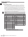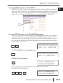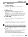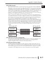
1
AUXILIARY FUNCTIONS
A PPENDIX
PPENDIX
A
In This Appendix:
Introduction . . . . . . . . . . . . . . . . . . . . . . . . . . . . . . . . . . . . . . . . . . .A–2
AUX 2* — RLL Operations . . . . . . . . . . . . . . . . . . . . . . . . . . . . . . . .A–4
AUX 3* — V-memory Operations . . . . . . . . . . . . . . . . . . . . . . . . . . .A–4
AUX 4* — I/O Configuration . . . . . . . . . . . . . . . . . . . . . . . . . . . . . .A–4
AUX 5* — CPU Configuration . . . . . . . . . . . . . . . . . . . . . . . . . . . . .A–5
AUX 6* — Handheld Programmer Configuration . . . . . . . . . . . . . . .A–8
AUX 7* — EEPROM Operations . . . . . . . . . . . . . . . . . . . . . . . . . . . .A–8
AUX 8* — Password Operations . . . . . . . . . . . . . . . . . . . . . . . . . . .A–9
Appendix A: Auxiliary Functions
Introduction
A
2
3
4
5
6
7
8
9
10
11
12
13
14
A
B
C
D
A–2
Purpose of Auxiliary Functions
Many CPU setup tasks involve the use of Auxiliary (AUX) Functions. The AUX Functions
perform many different operations, including clearing ladder memory, displaying the scan
time, and copying programs to EEPROM in the handheld programmer. They are divided
into categories that affect different system resources. You can access the AUX Functions from
DirectSOFT 5 or from the D2–HPP Handheld Programmer. The manuals for those products
provide step-by-step procedures for accessing the AUX Functions. Some of these AUX
Functions are designed specifically for the Handheld Programmer setup, so they will not be
needed (or available) with the DirectSOFT 5 package. Even though this Appendix provides
many examples of how the AUX functions operate, you should supplement this information
with the documentation for your choice of programming device.
NOTE: The Handheld Programmer may have additional AUX functions that are not supported with the
DL05 PLCs.
AUX Function and Description
DL05
AUX 2* — RLL Operations
21
22
23
24
Check Program
Change Reference
Clear Ladder Range
Clear All Ladders
*
*
*
*
AUX 3* — V-Memory Operations
31
Clear V Memory
*
AUX 4* — I/O Configuration
41
Show I/O Configuration
*
AUX 5* — CPU Configuration
51
53
54
55
56
57
58
59
5B
5D
Modify Program Name
Display Scan Time
Initialize Scratchpad
Set Watchdog Timer
Set Communication Port 2
Set Retentive Ranges
Test Operations
Override Setup
HSIO Interface Configuration
Scan Control Setup
NOTE:
*
AUX Function and Description
DL05
AUX 6* — Handheld Programmer Configuration
*
*
*
*
*
*
*
*
*
*
61
62
65
Show Revision Numbers
Beeper On / Off
Run Self Diagnostics
*
HP
HP
AUX 7* — EEPROM Operations
71
72
73
74
75
76
Copy CPU memory to HPP EEPROM
Write HPP EEPROM to CPU
Compare CPU to HPP EEPROM
Blank Check (HPP EEPROM)
Erase HPP EEPROM
Show EEPROM Type (CPU and HPP)
HP
HP
HP
HP
HP
HP
AUX 8* — Password Operations
81
82
83
Modify Password
Unlock CPU
Lock CPU
- Supported HP - Handheld Programmer function
DL05 Micro PLC User Manual, 6th Edition, Rev. C
*
*
*
Appendix A: Auxiliary Functions
Accessing AUX Functions via DirectSOFT 5
DirectSOFT 5 provides various menu options during both online and offline programming.
Some of the AUX functions are only available during online programming, some only during
offline programming, and some during both online and offline programming. The following
diagram shows an example of the PLC operations menu available within DirectSOFT 5.
Menu
Options
Accessing AUX Functions via the Handheld Programmer
You can also access the AUX functions by using the Handheld Programmer. Plus, remember
some of the AUX functions are only available from the HPP. Sometimes the AUX name or
description cannot fit on one display. If you want to see the complete description, just press
the arrow keys to scroll left and right. Also, depending on the current display, you may have
to press CLR more than once.
CLR
AUX FUNCTION SELECTION
AUX 2* RLL OPERATIONS
AUX
Use NXT or PREV to cycle through the menus
AUX FUNCTION SELECTION
AUX 3* V OPERATIONS
NEXT
Press ENT to select sub-menus
AUX 3* V OPERATIONS
AUX 31 CLR V MEMORY
ENT
You can also enter the exact AUX number to go straight to the sub-menu.
Enter the AUX number directly
CLR
D
B
3
1
AUX
AUX 3* V OPERATIONS
AUX 31 CLR V MEMORY
DL05 Micro PLC User Manual, 6th Edition, Rev. C
A
2
3
4
5
6
7
8
9
10
11
12
13
14
A
B
C
D
A–3
Appendix A: Auxiliary Functions
— RLL Operations
A AUX 2*RLL
Operations auxiliary functions allow you to perform various operations on the ladder
program.
2
AUX 21 Check Program
Both the Handheld and DirectSOFT 5 automatically check for errors during program entry.
3
However, there may be occasions when you want to check a program that has already been in
the CPU. Two types of checks are available:
4
• Syntax
• Duplicate References
5
The Syntax check will find a wide variety of programming errors, such as missing END
statements. If you perform this check and get an error, see Appendix B for a complete listing
6
of programming error codes. Correct the problem and then continue running the Syntax
check until the message, NO SYNTAX ERROR, appears.
Use the Duplicate Reference check to verify you have not used the same output coil reference
7
more than once. Note, this AUX function will also find the same outputs even if they have
been used with the OROUT instruction, which is perfectly acceptable.
8
This AUX function is available on the PLC Diagnostics sub-menu in DirectSOFT 5.
AUX 22 Change Reference
9
There will probably be times when you need to change an I/O address reference or control
relay reference. AUX 22 allows you to quickly and easily change all occurrences, (within an
10
address range), of a specific instruction. For example, you can replace every instance of X5
with X10.
11
AUX 23 Clear Ladder Range
There have been many times when we’ve taken existing programs and added or removed
12
certain portions to solve new application problems. By using AUX 23 you can select and
delete a portion of the program. DirectSOFT 5 does not have a menu option for this AUX
function, but you can just select the appropriate portion of the program and cut it with the
13
editing tools.
AUX 24 Clear Ladders
14
AUX 24 clears the entire program from CPU memory. Before you enter a new program, you
should always clear ladder memory. This AUX function is available on the PLC/Clear PLC
A
sub-menu within DirectSOFT 5.
B AUX 3* — V-memory Operations
AUX 31 Clear V-Memory
C
AUX 31 clears all the information from the V-memory locations available for general use.
This
AUX function is available on the PLC/Clear PLC sub-menu within DirectSOFT 5.
D
A–4
DL05 Micro PLC User Manual, 6th Edition, Rev. C
Appendix A: Auxiliary Functions
AUX 4* — I/O Configuration
AUX 41 Show I/O Configuration
This AUX function allows you to display the current I/O configuration on the DL05. Both
the Handheld Programmer and DirectSOFT 5 will show the I/O configuration.
AUX 5* — CPU Configuration
The following auxiliary AUX functions allow you to setup, view, or change the CPU
configuration.
AUX 51 Modify Program Name
DL05 PLCs can use a program name for the CPU program or a program stored on
EEPROM in the Handheld Programmer (multiple programs cannot be stored on the
EEPROM). The program name can be up to eight characters in length and can use any of the
available characters (A–Z, 0–9). AUX 51 allows you to enter a program name. You can also
perform this operation in DirectSOFT 5 by using the PLC/Setup sub-menu. Once you’ve
entered a program name, you can only clear the name by using AUX 54 to reset the system
memory. Make sure you understand the possible effects of AUX 54 before you use it!
AUX 53 Display Scan Time
AUX 53 displays the current, minimum, and maximum scan times. The minimum and
maximum times are the ones that have occurred since the last Program Mode to Run Mode
transition. You can also perform this operation from within DirectSOFT 5 by using the
PLC/Diagnostics sub-menu.
AUX 54 Initialize Scratchpad
The CPU maintains system parameters in a memory area often referred to as the
“scratchpad”. In some cases, you may make changes to the system setup that will be stored in
system memory. For example, if you specify a range of Control Relays (CRs) as retentive,
these changes are stored.
NOTE: You may never have to use this feature unless you have made changes that affect system
memory. Usually, you’ll only need to initialize the system memory if you are changing programs and
the old program required a special system setup. You can usually change from program to program
without ever initializing system memory.
AUX 54 resets the system memory to the default values. You can also perform this operation
from within DirectSOFT 5. by using the PLC/Setup sub-menu.
AUX 55 Set Watchdog Timer
DL05 PLCs have a “watchdog” timer that is used to monitor the scan time. The default value
set from the factory is 200 ms. If the scan time exceeds the watchdog time limit, the CPU
automatically leaves RUN mode and enters PGM mode. The Handheld displays the
following message E003 S/W TIMEOUT when the scan overrun occurs.
Use AUX 55 to increase or decrease the watchdog timer value. You can also perform this
operation from within DirectSOFT 5 by using the PLC/Setup sub-menu.
DL05 Micro PLC User Manual, 6th Edition, Rev. C
A
2
3
4
5
6
7
8
9
10
11
12
13
14
A
B
C
D
A–5
Appendix A: Auxiliary Functions
A
2
3
4
5
6
7
8
9
10
11
12
13
14
A
B
C
D
A–6
AUX 56 CPU Network Address
Since the DL05 CPU has an additional communication port, you can use the Handheld to
set the network address for port 2 and the port communication parameters. The default
settings are:
• Station address 1
• HEX mode
• Odd parity
You can use this port with either the Handheld Programmer, DirectSOFT 5, or, as a
communication port for either DirectNET or Modbus. Refer to either DirectNET or
Modbus manuals for additional information about communication settings required for
network operation.
NOTE: You will only need to use this procedure if you have port 2 connected to a network. Otherwise,
the default settings will work fine.
Use AUX 56 to set the network address and communication parameters. You can also
perform this operation from within DirectSOFT 5 by using the PLC/Setup sub-menu.
AUX 57 Set Retentive Ranges
DL05 CPUs provide certain ranges of retentive memory by default. Some of the retentive
memory locations are backed up by a super-capacitor, and others are in non-volatile FLASH
memory. The FLASH memory locations are V7400 to V7577 (may be non-volatile if MOV
instruction is used). The default ranges are suitable for many applications, but you can change
them if your application requires additional retentive ranges or no retentive ranges at all. The
default settings are:
DL05
Memory Area
Control Relays
V-Memory
Timers
Counters
Stages
Default Range
Available Range
C400 – C777
V1400 – V7777
None by default
CT0 – CT177
None by default
C0 – C777
V0 – V7777
T0 – T177
CT0 – CT177
S0 – S377
Use AUX 57 to change the retentive ranges. You can also perform this operation from within
DirectSOFT 5 by using the PLC/Setup sub-menu.
WARNING: The DL05 CPUs do not have battery-backed RAM. The super-capacitor will retain the
values in the event of a power loss, but only up to 3 weeks. (The retention time may be as short
as 4 1/2 days in 60°C operating temperature.)
AUX 58 Test Operations
AUX 58 is used to override the output disable function of the Pause instruction. Use AUX 58
to program a single output or a range of outputs which will operate normally even when
those points are within the scope of the pause instruction.
DL05 Micro PLC User Manual, 6th Edition, Rev. C
Appendix A: Auxiliary Functions
AUX 59 Bit Override
Bit override can be enabled on a point-by-point basis by using AUX 59 from the Handheld
Programmer or, by a menu option from within DirectSOFT 5. Bit override basically disables
any changes to the discrete point by the CPU. For example, if you enable bit override for X1,
and X1 is off at the time, then the CPU will not change the state of X1. This means that even
if X1 comes on, the CPU will not acknowledge the change. So, if you used X1 in the
program, it would always be evaluated as “off ” in this case. Of course, if X1 was on when the
bit override was enabled, then X1 would always be evaluated as “on”.
There is an advantage available when you use the bit override feature. The regular forcing is
not disabled because the bit override is enabled. For example, if you enabled the Bit Override
for Y0 and it was off at the time, then the CPU would not change the state of Y0. However,
you can still use a programming device to change the status. Now, if you use the
programming device to force Y0 on, it will remain on and the CPU will not change the state
of Y0. If you then force Y0 off, the CPU will maintain Y0 as off. The CPU will never update
the point with the results from the application program or from the I/O update until the bit
override is removed from the point. The following diagram shows a brief overview of the bit
override feature. Notice the CPU does not update the Image Register when bit override is
enabled.
Bit Override OFF
Bit Override ON
Input Update
Input Update
X128
OFF
Y128
OFF
C377
OFF
Force from
Programmer
Result of Program
Solution
...
...
...
...
...
...
X2
ON
Y2
ON
C2
ON
X1
ON
Y1
ON
C1
OFF
X0
OFF
Y0
OFF
C0
OFF
Image Register (example)
Force from
Programmer
Result of Program
Solution
AUX 5B Counter Interface Configuration
AUX 5B is used with the High-Speed I/O (HSIO) function to select the configuration. You
can choose the type of counter, set the counter parameters, etc. See Appendix E for a
complete description of how to select the various counter features.
AUX 5D Select PLC Scan Mode
The DL05 CPU has two program scan modes: fixed and variable. In fixed mode, the scan
time is lengthened to the time you specify (in milliseconds). If the actual scan time is longer
than the fixed scan time, then the error code E504 BAD REF/VAL is displayed. In variable
scan mode, the CPU begins each scan as soon as the previous scan’s activities complete.
DL05 Micro PLC User Manual, 6th Edition, Rev. C
A
2
3
4
5
6
7
8
9
10
11
12
13
14
A
B
C
D
A–7
Appendix A: Auxiliary Functions
A AUX 6* — Handheld Programmer Configuration
The following auxiliary functions allow you to setup, view, or change the Handheld
Programmer configuration.
2
AUX 61 Show Revision Numbers
As with most industrial control products, there are cases when additional features and
3
enhancements are made. Sometimes these new features only work with certain releases of
firmware. By using AUX 61 you can quickly view the CPU and Handheld Programmer
4
firmware revision numbers. This information (for the CPU) is also available from within
DirectSOFT 5 from the PLC/Diagnostics sub-menu.
5
AUX 62 Beeper On/Off
The Handheld has a beeper that provides confirmation of keystrokes. You can use Auxiliary
(AUX) Function 62 to turn off the beeper.
6
AUX 65 Run Self Diagnostics
7
If you think the Handheld Programmer is not operating correctly, you can use AUX 65 to
run a self diagnostics program. You can check the following items.
• Keypad
8
• Display
• LEDs and Backlight
9
• Handheld Programmer EEPROM check
10 AUX 7* — EEPROM Operations
The following auxiliary functions allow you to move the ladder program from one area to
11
another and perform other program maintenance tasks.
Transferrable Memory Areas
12
Many of these AUX functions allow you to copy different areas of memory to and from the
CPU and handheld programmer. The following table shows the areas that may be mentioned.
13
Option and Memory Type
DL05 Default Range
14
A
B
AUX 71 CPU to HPP EEPROM
C
AUX 71 copies information from the CPU memory to an EEPROM installed in the
Handheld Programmer. You can copy different portions of EEPROM (HP) memory to the
CPU memory as shown in the previous table.
D
1: PGM — Program
2: V — V-memory
3: SYS — System
4: etc (All)— Program, System and non-volatile V-memory
only
A–8
$00000 – $02047
V00000 – V07777
Non-selectable copies system parameters
Non-selectable
DL05 Micro PLC User Manual, 6th Edition, Rev. C
Appendix A: Auxiliary Functions
AUX 72 HPP EEPROM to CPU
AUX 72 copies information from the EEPROM installed in the Handheld Programmer to
CPU memory in the DL05. You can copy different portions of EEPROM (HPP) memory to
the CPU memory as shown in the previous table.
AUX 73 Compare HPP EEPROM to CPU
AUX 73 compares the program in the Handheld programmer (EEPROM) with the CPU
program. You can compare different types of information as shown previously.
AUX 74 HPP EEPROM Blank Check
AUX 74 allows you to check the EEPROM in the handheld programmer to make sure it is
blank. It’s a good idea to use this function anytime you start to copy an entire program to an
EEPROM in the handheld programmer.
AUX 75 Erase HPP EEPROM
AUX 75 allows you to clear all data in the EEPROM in the handheld programmer. You
should use this AUX function before you copy a program from the CPU.
AUX 76 Show EEPROM Type
You can use AUX 76 to quickly determine what size EEPROM is installed in the Handheld
Programmer.
AUX 8* — Password Operations
There are several AUX functions available that you can use to modify or enable the CPU
password. You can use these features during on-line communications with the CPU, or, you
can also use them with an EEPROM installed in the Handheld Programmer during off-line
operation. This will allow you to develop a program in the Handheld Programmer and
include password protection.
• AUX 81 — Modify Password
• AUX 82 — Unlock CPU
• AUX 83 — Lock CPU
AUX 81 Modify Password
You can use AUX 81 to provide an extra measure of protection by entering a password that
prevents unauthorized machine operations. The password must be an eight-character numeric
(0–9) code. Once you’ve entered a password, you can remove it by entering all zeros
(00000000). (This is the default from the factory.)
Once you’ve entered a password, you can lock the CPU against access. There are two ways to
lock the CPU with the Handheld Programmer.
• The CPU is always locked after a power cycle (if a password is present).
• You can use AUX 82 and AUX 83 to lock and unlock the CPU.
DL05 Micro PLC User Manual, 6th Edition, Rev. C
A
2
3
4
5
6
7
8
9
10
11
12
13
14
A
B
C
D
A–9
Appendix A: Auxiliary Functions
A
2
3
4
5
6
7
8
9
10
11
12
13
14
A
B
C
D
A–10
You can also enter or modify a password from within DirectSOFT 5 by using the
PLC/Password sub-menu. This feature works slightly differently in DirectSOFT 5. Once
you’ve entered a password, the CPU is automatically locked when you exit the software
package. It will also be locked if the CPU is power cycled.
WARNING: Make sure you remember the password before you lock the CPU. Once the CPU is
locked you cannot view, change, or erase the password. If you do not remember the password,
you have to return the CPU to the factory for password removal. It is the policy of
AutomationDirect to clear the PLC memory which includes the password and the program.
NOTE: The DL05 CPUs support multi-level password protection of the ladder program. This allows
password protection while not locking the communication port to an operator interface. The multilevel password can be invoked by creating a password with an upper case “A” followed by seven
numeric characters (e.g. A1234567).
AUX 82 Unlock CPU
AUX 82 can be used to unlock a CPU that has been password protected. DirectSOFT 5 will
automatically ask you to enter the password if you attempt to communicate with a CPU that
contains a password.
AUX 83 Lock CPU
AUX 83 can be used to lock a CPU that contains a password. Once the CPU is locked, you
will have to enter a password to gain access. Remember, this is not necessary with
DirectSOFT 5 since the CPU is automatically locked whenever you exit the software package.
DL05 Micro PLC User Manual, 6th Edition, Rev. C