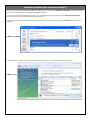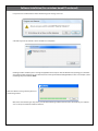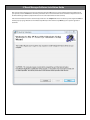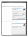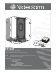
1
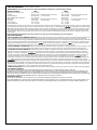
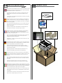
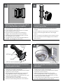
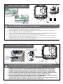
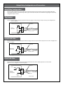
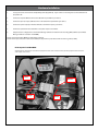
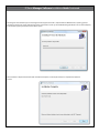
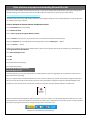
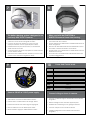
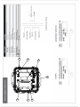
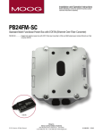
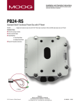
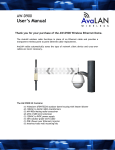
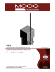
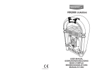
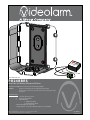
IPRS
12V
24V
ac
dc
01
Seria
l
# 00
Vin
1656
OranRed
sted
Vou withTeFC
ge
to co
C sta
mply
OranRed/Blac t
OranRed(+)
Ala ndards
ge/B k
ge(-)
Re
Br rm
Oran d/Black( lack
ge/B
Blacown
lack(-+)
k
)
www.videolarm.com
PB24BBRS
Power Box with Battery Backup and IP Reset
Installation and Operation Instructions for the following models:
PB24BBRS
Rugged cast aluminum power box PB24 plus battery backup.
Provides up to 25 minutes of extended power. Pole mounting clips included plus IP Reset.
Installation Steps
1.
Check the package contents
2.
Select Operation Mode
3.
Install Hardware
a. Timed Reset Mode
b. Intelligent Reset Mode
4. Read LED Operation instructions
5. Install Software- see IP Reset Manager Software (on CD-ROM)
B e fo r e a t t e m p t i n g t o c o n n e c t o r o p e r a t e t h i s p r o d u c t ,
p l e a s e r e a d t h e s e i n s t r u c t i o n s c o m p l e t e l y.
81-IN5418
01-29-2009
IMPORTANT SAFEGUARDS
1
Read these instructions.
2
Keep these instructions.
3
Heed all warnings
4
Follow all instructions.
5
Do not use this apparatus near water.
6
Clean only with damp cloth.
7
Do not block any of the ventilation openings. Install in accordance with the
SAFETY PRECAUTIONS
CAUTION
RISK OF ELECTRIC SHOCK
DO NOT OPEN
manufacturers instructions.
8
Cable Runs- All cable runs must be within permissible distance.
9
Mounting - This unit must be properly and securely mounted to a supporting
structure capable of sustaining the weight of the unit.
Accordingly:
a. The installation should be made by a qualified installer.
b. The installation should be in compliance with local codes.
c. Care should be exercised to select suitable hardware to install the unit, taking into
account both the composition of the mounting surface and the weight of the
unit.
10 Do not install near any heat sources such as radiators, heat registers, stoves, or other
apparatus ( including amplifiers) that produce heat.
11 Do not defeat the safety purpose of the polarized or grounding-type plug. A
polarized plug has two blades with one wider than the other. A grounding type
plug has two blades and a third grounding prong. The wide blade or the third
prong are provided for your safety. When the provided plug does not fit into your
outlet, consult an electrician for replacement of the obsolete outlet.
12 Protect the power cord from being walked on or pinched particularly at plugs,
convenience receptacles, and the point where they exit from the apparatus.
13 Only use attachment/ accessories specified by the manufacturer.
14 Use only with a cart, stand, tripod, bracket, or table specified by the manufacturer,
or sold with the apparatus. When a cart is used, use caution when moving the cart/
apparatus combination to avoid injury from tip-over.
15 Unplug this apparatus during lighting storms or when unused for long periods of time.
16 Refer all servicing to qualified service personnel. Servicing is required when the
apparatus has been damaged in any way, such as power-supply cord or plug is
damaged, liquid has been spilled of objects have fallen into the apparatus, the
apparatus has been exposed to rain or moisture, does not operate normally, or
has been dropped.
Be sure to periodically examine the unit and the supporting structure to make sure that the
integrity of the installation is intact. Failure to comply with the foregoing could result in the
unit separating from the support structure and falling, with resultant damages or injury to
anyone or anything struck by the falling unit.
UNPACKING
Unpack carefully. Electronic components can be
damaged if improperly handled or dropped. If an item
appears to have been damaged in shipment, replace
it properly in its carton and notify the shipper.
Be sure to save:
1 The shipping carton and packaging material.
They are the safest material in which to make
future shipments of the equipment.
2 These Installation and Operating Instructions.
SERVICE
If technical support or service is needed, contact us
at the following number:
TECHNICAL SUPPORT
AVAILABLE 24 HOURS
1 - 800 - 554 -1124
CAUTION: TO REDUCE THE RISK OF
ELECTRIC SHOCK, DO NOT REMOVE
COVER ( OR BACK). NO USER- SERVICEABLE PARTS INSIDE. REFER SEVICING TO
QUALIFIED SERVICE PERSONNEL.
The lightning flash with an arrowhead
symbol, within an equilateral triangle, is
intended to alert the user to the presence
of non-insulated “dangerous voltage”
within the product’s enclosure that may be
of sufficient magnitude to constitute a risk
to persons.
Este símbolo se piensa para alertar al usuario a la
presencia del “voltaje peligroso no-aisIado” dentro del
recinto de los productos que puede ser un riesgo de
choque eléctrico.
Ce symbole est prévu pour alerter I’utilisateur à la
presence “de la tension dangereuse” non-isolée dans la
clôture de produits qui peut être un risque de choc
électrique.
Dieses Symbol soll den Benutzer zum Vorhandensein der
nicht-lsolier “Gefährdungsspannung” innerhalb der
Produkteinschließung alarmieren die eine Gefahr des
elektrischen Schlages sein kann.
Este símbolo é pretendido alertar o usuário à presença
“di tensão perigosa non-isolada” dentro do cerco dos
produtos que pode ser um risco de choque elétrico.
Questo simbolo è inteso per avvertire I’utente alla
presenza “di tensione pericolosa” non-isolata all’interno
della recinzione dei prodotti che può essere un rischio di
scossa elettrica.
The exclamation point within an equilateral
triangle is intended to alert the user to
presence of important operating and
maintenance (servicing) instructions in the
literature accompanying the appliance.
Este símbolo del punto del exclamation se piensa para
alertar al usuario a la presencia de instrucciones
importantes en la literatura que acompaña la
aplicación.
Ce symbole de point d’exclamation est prévu pour
alerter l’utilisateur à la presence des instructions
importantes dans la littérature accompagnant
l’appareil.
Dieses Ausruf Punktsymbol soll den Benutzer zum
Vorhandensein de wichtigen Anweisungen in der
Literatur alarmieren, die das Gerät begleitet.
Este símbolo do ponto do exclamation é pretendido
alertar o usuário à presença de instruções importantes
na literatura que acompanha o dispositivo.
Questo simbolo del punto del exclamaton è inteso per
avvertire l’utente alla presenza delle istruzioni importanti
nella letteratura che accompagna l'apparecchio.
LIMITED WARRANTY FOR VIDEOLARM INC. PRODUCTS
VIDEOLARM INC. warrants this Product to be free from defects in material or workmanship,as follows:
PRODUCTCATEGORY
PARTS
LABOR
All Enclosures and Electronics
Five (5) Years
Five (5) Years
Pan/Tilts
Three (3) Years **6 months if used in autoscan
Three (3) Years **6 months if used in autoscan
/tour operation
Poles/PoleEvators
Three (3) Years /tour operation
Three (3) Years
Warrior/Q-View/I.R. Illuminators
Five (5) Years
Five (5) Years
Five (5) Years
SView Series
Five (5) Years **6 months if used in autoscan
**6 months if used in autoscan
/tour operation
/tour operation
Controllers
Five (5) Years
Five (5) Years
Power Supplies
Five (5) Years
Five (5) Years
Accessory Brackets
Five (5) Years
Five (5) Years
During the labor warranty period, to repair the Product, Purchaser will either return the defective product, freight prepaid, or deliver it to Videolarm Inc.
an equal degree of protection with a
Decatur GA. The Product to be repaired is to be returned in either its original carton or a similar package
RMA # (Return Materials Authorization number) displayed on the outer box or packing slip. To obtain a RMA# you must contact our Technical Support
Team at 800.554.1124, extension 101. Videolarm will return the repaired Product freight prepaid to Purchaser. Videolarm is not obligated to provide
Purchaser with a substitute unit during the warranty period or at any time. After the applicable warranty period, Purchaser must pay all labor and/or
parts charges.
The limited warranty stated in these product instructions is subject to all of the following terms and conditions:
TERMS AND CONDITIONS
1. NOTIFICATIONOF CLAIMS: WARRANTYSERVICE: If Purchaser believes that the Product is defective in material or workmanship, then written notice
with an explanation of the claim shall be given promptly by Purchaser to Videolarm but all claims for warranty service must be made within the
warranty period. If after investigation Videolarm determines that the reported problem was not covered by the warranty, Purchaser shall pay Videolarm
for the cost of investigating the problem at its then prevailing per incident billable rate. No repair or replacement of any Product or part thereof shall
extend the warranty period as to the entire Product. The
warranty on the repaired part only shall be in
for a period of ninety (90) days
following the repair or replacement of that part or the remaining period of the Product parts warranty, whichever is greater.
2. EXCLUSIVE REMEDY: ACCEPTANCE:Purchaser’s exclusive remedy and Videolarm’s sole obligation is to supply (or pay for) all labor necessary to repair
any Product found to be defective within the warranty period and to supply, at no extra charge, new or rebuilt replacements for defective parts.
3. EXCEPTIONS TO LIMITED WARRANTY: Videolarm shall have no liability or obligation to Purchaser with respect to any Product requiring service
during the warranty period which is subjected to any of the following: abuse, improper use: negligence, accident, lightning damage or other acts
of God (i.e., hurricanes, earthquakes),
failure of the end-user to follow the directions outlined in the product instructions, failure of the
end-user to follow the maintenance procedures recommended by the International Security Industry Organization, written in product instructions,
for regular
or recommended in the service manual for the Product. Furthermore, Videolarm shall have no liability where a schedule is
replacement or maintenance or cleaning of certain parts (based on usage) and the end-user has failed to follow such schedule; attempted repair by
personnel; operation of the Product outside of the published environmental and electrical parameters, or if such Product’s original
(trademark, serial number) markings have been defaced, altered, or removed. Videolarm excludes from warranty coverage Products sold
AS IS and/or WITH ALL FAULTS and excludes used Products which have not been sold by Videolarm to the Purchaser. All software and accompanying
documentation furnished with, or as part of the Product is furnished “AS IS” (i.e., without any warranty of any kind), except where expressly provided
otherwise in any documentation or license agreement furnished with the Product.
4. PROOF OF PURCHASE: The Purchaser’s dated bill of sale must be retained as evidence of the date of purchase and to establish warranty eligibility.
DISCLAIMEROF WARRANTY
EXCEPT FOR THE FOREGOING WARRANTIES, VIDEOLARM HEREBY DISCLAIMS AND EXCLUDES ALL OTHER WARRANTIES, EXPRESS OR IMPLIED,
INCLUDING, BUT NOT LIMITED TO ANY AND/OR ALL IMPLIED WARRANTIES OF MERCHANTABILITY, FITNESS FOR A PARTICULAR PURPOSE AND/OR ANY WARRANTY WITH
REGARD TO ANY CLAIM OF INFRINGEMENT THAT MAY BE PROVIDED IN SECTION 2-312(3) OF THE UNIFORM COMMERCIAL CODE AND/OR IN ANY OTHER COMPARABLE
STATE STATUTE. VIDEOLARM HEREBY DISCLAIMS ANY REPRESENTATIONS OR WARRANTY THAT THE PRODUCT IS COMPATIBLE WITH ANY COMBINATION OF NON-VIDEOLARM
PRODUCTS OR NON-VIDEOLARM RECOMMENDED PRODUCTS PURCHASER CHOOSES TO CONNECT TO PRODUCT.
LIMITATION OF LIABILITY
THE LIABILITY OF VIDEOLARM, IF ANY, AND PURCHASER’S SOLE AND EXCLUSIVE REMEDY FOR DAMAGES FOR ANY CLAIM OF ANY KIND
WHATSOEVER, REGARDLESS OF THE LEGAL THEORY AND WHETHER ARISING IN TORT OR CONTRACT, SHALL NOT BE GREATER THAN THE ACTUAL PURCHASE PRICE OF THE
PRODUCT WITH RESPECT TO WHICH SUCH CLAIM IS MADE. IN NO EVENT SHALL VIDEOLARM BE LIABLE TO PURCHASER FOR ANY SPECIAL, INDIRECT, INCIDENTAL, OR
CONSEQUENTIAL DAMAGES OF ANY KIND INCLUDING, BUT NOT LIMITED TO, COMPENSATION, REIMBURSEMENT OR DAMAGES ON ACCOUNT OF THE LOSS OF PRESENT
OR PROSPECTIVE PROFITS OR FOR ANY OTHER REASON WHATSOEVER.
Electrical Specifications
Contents of Box
PB24BB
English
Input Power: 120 VAC/240VAC 1A/.5A Power Consumption: 1Amp
(120 Watts) at 120 VAC Power Output: 84 VA at 24 VAC 52 Watts
Heater/Blower 32 Watts Camera Power
An all pole main switch with a contact of at least 3mm in each
pole shall be incorporated in the electrical installation of the
building.
As Ferramentas Requereram: chave de fenda flathead do
150"7/16 de chave da chave ou do soquete 9/16 ou soquete
Italiano
Alimentazione in ingresso Di Entrata: 120 Assorbimento di corrente
Di energia di VAC/240VAC 1A/.5A: 1Amp (120 watt) a 120 VCA di
uscita di alimentazione: VA 84 a 24 VCA 52 watt di Heater/Blower
32 watt di alimentazione della macchina fotografica
Tutto l'interruttore principale del palo con un contatto almeno di
3mm in ogni palo sarà compreso nell'installazione elettrica della
costruzione.
Attrezzi Richiesti: cacciavite a testa piatta del 150"7/16 di chiave
dallo zoccolo o dalla chiave 9/16 o zoccolo
to suppo
il
e-m a
d
se n
or
24
11
455
0-
180
Todo o interruptor principal do pólo com um contato ao menos
de 3mm em cada pólo será incorporado na instalação elétrica
do edifício.
n. F
or s
up
po
rt c
all
Portuguese
Poder De Entrada: 120 Consumo De Potência de VAC/240VAC
1A/.5A: 1Amp (120 watts) em 120 VAC de saída de poder: VA 84
em 24 VAC 52 watts de Heater/Blower 32 watts de poder da
câmera
i s stri ctly fo rb
pl icati on
idde
Werkzeuge Erforderten: 150"Flachkopfschraubenzieher 7/16
Schlüssel-oder Einfaßung 9/16 Schlüssel oder Einfaßung
du
An y
ds.
Ein aller Pfostenhauptschalter mit einem Kontakt von 3mm
mindestens in jedem Pfosten wird in der elektrischen Installation
des Gebäudes enthalten.
ar
nd
sta
CC
Deutsch
Zugeführte Energie: 120 VAC/240VAC 1A/.5A Leistungsaufnahme:
1Amp (120 Watt) bei 120 VAC Abgabeleistung: VA 84 bei 24 VAC
52 Watt Heater/Blower 32 Watt Kamera-Energie
ply
Outils Requis : tournevis à tête plate de 150"7/16 clé de clé ou de
douille 9/16 ou douille
IPRS01
om
Un tout le commutateur principal de poteau avec un contact au
moins de 3mm dans chaque poteau sera incorporé dans
l'installation électrique du bâtiment.
to
c
Français
Puissance D'entrée : 120 Puissance D'Énergie de VAC/240VAC
1A/.5A : 1Amp (120 watts) à 120 VCA de rendement de
puissance : VA 84 à 24 VCA 52 watts de Heater/Blower 32 watts
de puissance d'appareil-photo
Application Software
for
IP RESET
rm IPR S01 dev
ices o
nly.
Tes
te d
Herramientas Requeridas: destornillador de cabeza llana del
150"7/16 llave de la llave o del zócalo 9/16 o zócalo
deo la
For V i
Todo el interruptor principal del poste con un contacto de por lo
menos 3m m en cada poste será incorporado en la instalación
eléctrica del edificio.
F
th
wi
Español
Energía De Entrada: 120 Consumo De Energía de VAC/240VAC
1A/.5A: 1Amp (120 vatios) en 120 VAC de salida de energía: VA
84 en 24 VAC 52 vatios de Heater/Blower 32 vatios de energía de
la cámara fotográfica
rt at vid eolar m
.com
Tools Required: .150” Flathead Screwdriver 7/16 Wrench or Socket
9/16 Wrench or Socket
1
2
Wall Mounting: Attach unit securely with (4)
3/8” or 8mm hardware (not supplied).
• La pared que monta la caja de la energía es posible,
pero el hardware no es incluido.
• Le mur montant la boîte de puissance est possible,
mais le matériel n'est pas inclus.
• Die Wand, die den Energie Kasten anbringt, ist
möglich, aber die Kleinteile sind nicht enthalten.
• A parede que monta a caixa do poder é possível,
mas a ferragem não é incluída.
• La parete che monta la scatola di alimentazione è
possibile, ma i fissaggi non sono inclusi.
3
Wall Mount
Gasket
The power box may be pole mounted with
the pole support clips.
• Ésta es la plantilla del montaje para la caja de la
energía.
• C'est le calibre de support pour la boîte de puissance.
• Dieses ist die Montageschablone für den Energie
Kasten.
• Este é o molde da montagem para a caixa do poder.
• Ciò è la mascherina del montaggio per la scatola di
alimentazione.
4
3/8” Bolts
Washer
3/8” Nut and Lockwashers
Conduit Fitting
The wall mount bracket must be attached
using the gasket as shown.
This is the assembled unit with the housing
and conduit.
• El soporte del montaje de la pared se debe unir
usando la junta según lo demostrado.
• La parenthèse de bâti de mur doit être jointe utilisant
la garniture comme montrée.
• Der Wandeinfassung Haltewinkel muß mit der Dichtung angebracht werden, wie gezeigt worden.
• O suporte da montagem da parede deve ser unido
usando a gaxeta como mostrado.
• La staffa del supporto della parete deve essere
fissata per mezzo della guarnizione come indicata.
• El soporte del montaje de la pared se debe unir
usando la junta según lo demostrado.
• La parenthèse de bâti de mur doit être jointe utilisant
la garniture comme montrée.
• Der Wandeinfassung Haltewinkel muß mit der
Dichtung angebracht werden, wie gezeigt worden.
• O suporte da montagem da parede deve ser unido
usando a gaxeta como mostrado.
• La staffa del supporto della parete deve essere fissata
per mezzo della guarnizione come indicata.
4b
INPUT: (120VAC or 240VAC)
5b
220-240VAC INPUT
110-120VAC INPUT
240Vac
120Vac Input
Input
Main
Switch
Line (L) and Neutral (N) wires should be connected as marked on the board and plugged
into the corresponding voltage for the input single phase.
Los alambres de la línea (l) y del hilo neutro (n) se deben conectar según lo marcados en el tablero y tapados en el voltaje correspondiente para la monofásico de la entrada.
Des fils de la ligne (l) et du neutre (n) devraient être reliés comme marqué sur le conseil et branché à la
tension correspondante pour le monophasé d'entrée.
Linie (L) und des Neutralen (N) Leitungen sollten angeschlossen werden, wie auf dem Brett gekennzeichnet
worden und in die entsprechende Spannung für das Eingang einphasige verstopft.
Os fios da linha (L) e do ponto morto (N) devem ser conectados como marcados na placa e plugged na
tensão correspondente para a fase monofásica da entrada.
I legare della linea (l) e del neutrale (n) dovrebbero essere collegati come contrassegnato sul bordo ed
inserito la tensione corrispondente per la monofase dell'input.
24VAC (Heater)/12DC (Camera)
6OUTPUT:
b
HEATERS CAMERA
Connect
Housing
Power
Optional 24Vac
24Vac/12VDC
Output
Power To Housing
Main
Switch
Internal resettable fuses are supplied for the main 24VAC output lines. Do not connect heaters
to camera output. The PB24 is not designed for 3 phase or 208V systems.
Los fusibles restaurables internos se proveen para las líneas de salida principales 24VAC. No conecte los
calentadores con la salida de la cámara fotográfica. El PB24 no se diseña para 3 fases o sistemas 208V.
Des fusibles réglables internes sont fournis pour les lignes de la sortie 24VAC principales. Ne reliez pas les
réchauffeurs au rendement d'appareil-photo. Le PB24 n'est pas conçu pour 3 phases ou systèmes 208V.
Interne rückstellbare Sicherungen werden für die Haupt-24VAC Ertragskurven geliefert. Schließen Sie Heizungen nicht an Kameraausgang an. Das PB24 ist nicht für 3 Phase oder Systeme 208V bestimmt.
Os fusíveis resettable internos são fornecidos para as linhas de saída 24VAC principais. Não conecte calefatores à saída da câmera. O PB24 não é projetado para 3 fases ou sistemas 208V.
I fusibili resettable interni sono forniti per le linee di uscita principali 24VAC. Non colleghi i riscaldatori all'uscita
della macchina fotografica. Il PB24 non è progettato per 3 fase o sistemi 208V.
Operating Modes
The IP Reset operates in one of two modes, Intelligent Reset Mode and Timed Reset Mode. IP Reset automatically detects the operating mode by monitoring the I/O Detect input. If IP Reset detects a change in the I/O Detect input, it will enter the Intelligent Reset mode. Otherwise, IP Reset will remain in Timed Reset mode. You can choose to use Timed Mode by twisting the I/O Detect wires together and securing them with the wire nut.
Intelligent Reset Mode
The Intelligent Reset Mode monitors a relay output on the device being protected. The relay output on the IP device is commanded to toggle at a pre-determined interval using IP Reset Manager Software or other network software designed to sup
port IP Reset. When IP Reset detects the loss of the relay toggle, after a pre-determined detection period, it power restarts the protected device. Generally, a power reset will restore the device to proper operation. After 2 failed attempts to restore the device’s operation, IP Reset will re-start the protected device once every four hours (fault detection mode).
Timed Reset Mode
The Timed Reset Mode, simply cycles power on the protected device every 12 or 24 hours depending upon the model ordered.
The IP Reset resets the protected device every 12 hours. The IP Reset resets the protected device every 24 hours. When used in Timed Reset mode, IP Reset connects directly inline with the device’s power, does not use the I/O Detect Cable and does not require any remote commanding software.
NOTE:
If Timed Reset Mode is used on a PTZ camera, the camera will typically reset to its home position upon reset.
For this reason, we recommend using Intelligent Reset Mode whenever possible for PTZ cameras.
Output Relay Configuration and Connections
Output Relay Configuration
The relay output configurations vary based on the manufactures design. Because of these variations, the IP Reset I/O Detect input needs to operate in one of three ways. Refer to your camera user manual for more information regarding the output relay configuration of your camera.
Dry Contact
The first and most common method requires the IP Reset to supply current to the dry contacts of a relay. This configuration is shown in Figure 5.
Striped Wire
Camera
Dry Contact
I/O Detect Cable
Figure 5: Dry Contact Relay I/O Detect Connection
Passive Solid-State
The second method is similar, requiring the IP Reset to supply current to an open collector output transistor. This configuration is shown in Figure 6.
Striped Wire
Camera Open
Collector Relay
I/O Detect Cable
Figure 6. Passive Solid-State Relay I/O Detect Connection
Active Solid-State
The third and least common method is the emitter follower where the camera output supplies the current used for detection. In this configuration is shown in Figure 7.
Striped Wire +
+ Volts
Camera
Solid State
Sourcing Relay
Plain Wire I/O Detect Cable
Figure 7: Active Solid-State Relay I/O Detect Connection
Hardware Installation
1.
Locate your camera in the Camera Compatibility Chart (Appendix A). If your camera is not listed, please contact Videolarm at (800)-554-1124.
2.
Connect the striped I/O Detect wire to the I/O terminal specified for your device.
3.
Connect the plain (no stripe) I/O Detect wire to the I/O terminal specified for your device.
4.
Connect the power output pin from the IP Reset to the Power input on your device.
5.
Connect the power from the transformer to the power input in the IP Reset.
6.
Add your device’s configuration to the IP Reset Manager Software or Network video recording (NVR) software (See IP Reset Manager Software installation in CD-ROM).
Note 1: Connection polarity MUST be observed for all devices.
Note 2: If the input connections need to be modified, the striped wire is plus VDC and the solid wire is ground (0 VDC).
IP Reset power box PB24BBRS
Attach the brown and black wire to the blue and purple wire of the dome. Inside the dome, attach the purple and blue wire to the
alarm output of the camera.
56
IPRS01 Serial # 0016
24Vac
12Vdc
Vin
Red
Orange O
Red(+)
Orange(-) O
Tested to comply
with FCC standards
Alarm
Vout
Brown
Red/Black
Black
range/Black
Red/Black(+)
range/Black(-)
Blue
Purple
Brown
Black
Hardware Installation (cont.)
IP Reset® LED Operation
LED Operation
Green LED – Device Power Indicator
•
ON : Power On to Device
•
OFF : Power Off to Device
Yellow LED – Communication/Signal Status
•
Timed Mode
: Flashes every second
•
Intelligent Mode : Flashes every 90 Seconds (On = input High, Off = input Low)
Red LED – Operation Mode Indicator
•
ON : Intelligent Mode, device operating as expected
•
OFF : Timed Mode
•
Flashing : Intelligent Mode, device fault detected
Software Installation (For a windows based PC)
If there is a pre-existing version of the IP Reset Manager Software on your computer go to “Add/Remove Programs “from the MS Windows
Control Panel and remove it before beginning a new software installation.
To remove a pre-existing IP Reset Manager Installation, go to the Windows “Control Panel” and click on the “Add or Remove Programs”
software icon. After a few seconds the following window will appear:
From the “Add or Remove Programs” menu below in Windows XP, select the program “IP Reset”. Click on the “Remove” button (See screen
shot below)
In Windows XP/XP PRO
IP Reset
From the “Uninstall or change a program” menu in Windows Vista, double click on the “IP Reset by Videolarm” application.
In Windows Vista
In response to the confirmation box “Add or Remove Programs” message. Click “Yes”.
Software Installation (For a windows based PC continued)
In response to the confirmation box “Add or Remove Programs” message. Click “Yes”.
A window may show up as follows: Let this window run to completion.
Following the above window if you are removing the application from a computer with the Windows Vista operating system, a window
(not shown) may appear with the title “User Account Control”. It will say “An Unidentified Program Wants to Access Your Computer”, if this
window appears you should click “Allow”.
IP ResetSetup
While the software is being removed you will see
the following window
Wait till the above window goes away. At this point the IP Reset Manager Software will have been removed from your computer.
You can now proceed with the software installation.
IP Reset Manager Software Installation Guide
After you have fully removed any pre-existing installations of IP Reset Manager (see section “Removing IP Reset Software” from your system), insert the CDROM that came with your IP Reset device into the hard drive of the networked computer that will run the IP Reset Manager Software (computer must be on the same network with the video cameras)
If the installation file doesn’t launch automatically, Double click on “setup.msi” file in the root directory of the supplied CDROM. A window pops up saying “Welcome to the IP Reset Setup Wizard”, click the box that says “Next>”, if you accept the registration
statement.
IP Reset Manager Software Installation Guide Continued
A Window pops up that says “Select Installation Folder”, if the radio button “just me” is selected, (shown below) than change it to
the radio button “Everyone”, as shown below
A window will appear that says, “Confirm Installation”, Click “Next >” to confirm the installation!
IP Reset Manager Software Installation Guide Continued
Following the above window if you are installing the IP Reset application from a computer with the Windows Vista operating system, a
window (not shown) may appear with the title “User Account Control”. It will say “An Unidentified Program Wants to Access Your Computer”,
if this window appears you should click the “Allow” option.
Once installation completes the final window “Installation Complete” is launched, Click “Close” to complete the installation
process.
Older machines may require downloading Microsoft Dot Net
If you are on an older windows machine that does not have a current version of Microsoft’s Dot Net libraries, you may get a message from
Windows requiring you to download the latest version of Microsoft .Net. At this point you will have log on to Microsoft at:
http://msdn.microsoft.com/en-us/netframework/default.aspx
And download the latest version of Microsoft’s .Net libraries. After doing this double click on the downloaded files to install .Net. Once this
has completed reboot your computer.
Create an Exception for IP Reset Software from Windows Firewall
Select “Control Panel” from the start Menu
Select “Windows Firewall”
Click on “Allow a program through the Windows Firewall”
Click on “continue” if asked are you sure you want to do this or the “User Account Control” window appears
Under the “exceptions” tab on the “Windows Firewall Settings” menu, click the “Add Program …” Button
Click on the “Browse …” button
Browse to the installation directory for the IP Reset software. Unless you changed this directory for the installation you should browse to
“C:\\Program Files\Videolarm\IP Reset
Select “IPResetConfigurator.exe”
Click “OK”
Click “OK”
Exit the “Windows Firewall Settings”
Exit the “Windows Firewall”
Start the IP Reset Configuration Tool,
“IPResetConfigurator.exe”
(For the following steps, you may get a message that says “.NET Framework” needs to be upgraded, In this case follow the instructions and
upgrade “.NET” before continuing)
Restart your computer and the centralized IP Reset control service launches automatically. You will see the IP Reset configurator application
on the users startup menu under the “All Programs” option. The name of the IP Reset configuration program is “IPResetConfiguratore.exe”.
The application is also installed on the user’s desktop and may be launched by clicking the IP Reset desktop Icon shown below:
IPResetConfig
urator.exe
Once launched the IP Reset Configuration application resides in the users “control tray” on the bottom right hand side of the screen. If the
IP Reset application is enabled the “Sunburst” Icon will blink. If the application is disabled the icon stays solid. The user can then program IP
Reset devices by using the mouse button and right clicking on this icon in the users tray.
IP Reset Icon in users Control Tray (red starburst)
You are now ready to run the IP Reset Configuration Software. For usage information refer to application users document “IP
ResetSoftwareUsersGuide.pdf” which is enclosed as a PDF with the CD-ROM. After successful installation the user’s guide and operations
guide can be found on your computer in the following directory:
“C:\Program Files\Videolarm\IP Reset\IP Reset_Software_User_s Guide.pdf” is the application manual used to configure IP Reset devices
from the computer. It describes installing the IP Reset devices to work with your cameras or other devices.
If you ever want to run the IP Reset software directly, browse to the IP Reset installation Directory, “C:/Program Files/Videolarm/IP Reset”,
and double click on the file “IPResetConfigurator.exe”. This will force the configuration application to launch manually.
7
The battery backup system is designed to be
used only with 12VDC Cameras.
8
When used with the FDW75C2N or
RHW75C2N remove Dome from housing.
• El sistema de reserva de batería se diseña para ser utilizado
solamente con las cámaras fotográficas 12VDC.
• Cuando está utilizado con el FDW75C2N o el RHW75C2N
quite la bóveda de la cubierta.
• Le réseau de réserve de batterie est conçu pour être
employé seulement avec les appareils-photo 12VDC.
• Une fois utilisé avec le FDW75C2N ou le RHW75C2N enlevez le
dôme du logement.
• Das Batteriereservesystem ist entworfen, nur mit Kameras
12VDC benutzt zu werden.
• Wenn Sie mit dem FDW75C2N oder dem RHW75C2N verwendet werden, entfernen Sie Haube vom Gehäuse.
• O sistema backup de bateria é projetado ser usado somente
com as câmeras 12VDC.
• Quando usado com o FDW75C2N ou o RHW75C2N remova a
abóbada da carcaça.
• Il sistema di riserva della batteria è destinato per essere usato
soltanto con le macchine fotografiche 12VDC.
• Una volta usato con il FDW75C2N o il RHW75C2N rimuova la
cupola da alloggiamento.
9
Remove 24VAC to 12VDC power supply.
10
Power And Control Leads
RED
Camera Power 12VDC(+)
ORANGE
Camera Power 12VDC(-)
BLUE
Alarm 1
VILOET
Alarm 2
GRAY
Alarm 3
WHITE
Common
Connect wiring as shown to camera.
• Quite 24VAC a la fuente de alimentación 12VDC.
• Conecte el cableado según lo demostrado con la cámara
fotográfica.
• Enlevez 24VAC sur l'alimentation de l'énergie 12VDC.
• Reliez le câblage comme montré à l'appareil-photo.
• Entfernen Sie 24VAC zum 12VDC Spg.Versorgungsteil.
• Schließen Sie Verdrahtung an, wie gezeigt an Kamera.
• Remova 24VAC à fonte de alimentação 12VDC.
• Conecte a fiação como mostrado à câmera.
• Rimuova 24VAC al gruppo di alimentazione 12VDC.
• Colleghi i collegamenti come indicato alla macchina
fotografica.
6
7
5
4
3
2
1
7
N/S
IPRS01
IP Reset
Replacement Battery
Battery Bracket
RPVL3085
RP70BAT1214
Battery Charger Curcuit
RP70TVLSMP3
RP70TRAN11
TM
Product Registration/Warranty
Thank you for choosing Videolarm. We value your patronage and are solely committed to
providing you with only the highest quality products available with unmatched customer service
levels that are second-to-none in the security industry.
Should a problem arise, rest assure that Videolarm stands behind its products
by offering some of the most impressive warranty plans available: 3 Years
on all Housings, Poles, Power Supplies, and Accessories and 5 Years on
all camera systems (SView, QView, Warriors), and InfraRed Illuminators.
Register Your Products
Option 1: Online Option 2: Mail-In
Take a few moments and validate your purchase with our Online Product Registration Form
www.videolarm.com/productregistration.jsp
at
or complete and mail-in the bottom portion of this flyer.
Register your recent Videolarm purchases and benefit from the following:
• Simple and Trouble-Free RMA process
• Added into customer database to receive product updates / news
• Eliminate the need to archive original purchase documents:
Receipts, Purchase Orders, etc…
Main Contact Info
Cut at the dotted Line
Place in envelope, affix stamp and mail to: Videolarm ATTN: Warranty
2525 Park Central Ave.
Decatur, GA 30035
First Name:
Last Name:
Professional Title:
Company:
Address 1:
Address 2:
City:
State / Province/Country:
Zip / Postal Code:
Phone Number:
Product Information Please Circle One:
Name & Location of Company / Store where Purchased:
(City, State, Country)
Videolarm Product ID
Product Description
Serial #
(Available only for Camera Systems, IR Illuminators, Wireless Devices)
PO#
E-mail Address:
Business
Personal