1
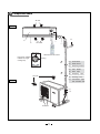
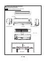
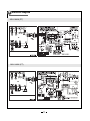
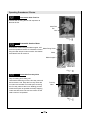
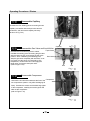
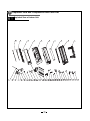
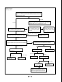
SERVICE MANUAL
)
NORDIC
SERIES
ASH-18AIN (PT), ASH-24AIN (PT)
2
Specifications and Technical Parameters
ASH-18AIN (PT)
Model
COOLING
Function
Rated Voltage
HEATING
ASH-24AIN (PT)
COOLING
220-240V~
Rated Frequency
Total Capacity (W) (Low / High /
Standard)
Total Capacity (Btu/h) (Low / High /
Standard)
Power Input (W)
HEATING
220-240V~
30 / 100 / 75
30 / 100 / 72
25 / 100 / 82
25 / 100 / 74
2500 / 5800 / 5300
2300 / 6400 / 5850
2000 / 6800 / 6500
1600 / 8200 / 6500
5460 / 28000 /
22200
470 / 3250 / 1800
8500 / 19800 /
18100
620 / 2200 / 1560
550 / 2250 / 1620
6800 / 23200 /
22200
520 / 2450 / 2020
Rated Input (W)
2400
2450
3200
3250
Rated Current (A)
10.48
10.71
14
14.2
3
Air Flow Volum e (m /h) (H/M/L)**
Dehum idifying Volum e (l/h)
EER / C.O.P (W/W)
Energy Clas s
Model of Indoor Unit
Fan Motor Speed (r/m in)
(H/M/L)
Output of Fan Motor (w)
Input of Heater (w)
Fan Motor Capacitor (uF)
Fan Motor RLA(A)
Fan Type-Piece
Diam eter-Length (m m )
Evaporator
Pipe Diam eter (m m )
Row-Fin Gap(m m )
Indoor
Coil length (l) x height (H) x
unit
coil width (L)
Swing Motor Model
Output of Swing Motor (W)
Fus e (A)
Sound Pres s ure Level dB
(A) (H/M/L)
Sound Power Level dB (A)
(H/M/L)***
Dim ens ion (W/H/D) ( m m )
Dim ens ion of Package
(L/W/H) ( m m )
Net Weight /Gros s Weight
(kg)
2300 / 6400 / 5850
900 / 800 / 675
850 / 750 / 650
2
2.4
3.40 / 3.61
3.22 / 3.61
A/A
A/A
ASH-18AIN (PT)
ASH-24AIN( PT)
1400/1200/1100
1400/1200/1100
45
45
/
/
3
3
0.2
0.2
Cros s flow fan – 1
Cros s flow fan – 1
φ 96 X 797
Alum inum fin-copper tube
φ 96 X 797
Alum inum fin-copper tube
Φ7
2-1.6
Φ7
2-1.6
787X400X25.4
787X400X25.4
MP28AA
MP28AA
2
2
PCB 3.15A Trans form er 0.2A
PCB 3.15A Trans form er 0.2A
48/43/40
48/43/40
58/53/50
58/53/50
1020X319X234
1020X319X234
1078X325X390
1078X325X390
13/17
13/17
Model of Outdoor Unit
Compressor Manufacturer/trademark
Compressor Model
Compressor Type
L.R.A. (A)
Compressor RLA(A)
Compressor Power Input(W)
Overload Protector
Throttling Method
Starting Method
Working Temp Range (℃)
Condenser
Pipe Diameter (mm)
Rows-Fin Gap(mm)
Coil length (l) x height (H) x coil width
(L)
Fan Motor Speed (rpm)
Output of Fan Motor (W)
Outdoor
Fan Motor RLA(A)
unit
Fan Motor Capacitor (uF)
Air Flow Volume of Outdoor Unit
Fan Type-Piece
Fan Diameter (mm)
Defrosting Method
Climate Type
Isolation
Moisture Protection
Permissible Excessive Operating
Pressure for the Discharge Side(MPa)
Permissible Excessive Operating
Pressure for the Suction Side(MPa)
Sound Pressure Level dB (A) (H/M/L)
Sound Power Level dB (A) (H/M/L)
Dimension (W/H/D) ( mm)
Dimension of Package (L/W/H)( mm)
Net Weight /Gross Weight (kg)
Refrigerant Charge (kg)
Length (m)
Gas additional charge(g/m)
Connec
Liquid Pipe (mm)
Outer
tion
Diameter Gas Pipe (mm)
Pipe
Max
Height (m)
Distance Length (m)
ASH-18AIN (PT)
SANYO
C-6RVN93H0V
Double Rotary
41
7
1610
1NT11L-3979
Capillary
Transducer starting
-15℃≤T≤46℃
Aluminum fin-copper tube
7
2-1.4
ASH-24AIN (PT)
SANYO
C-6RZ146H1B
Double Rotary
32
7.78
1500
1NT11L-3979
Capillary throttling
Transducer starting
-15℃≤T≤46℃
Aluminum fin-copper tube
Φ9.52
2-1.4
838×660×25.4
731X813X44
780/600
60W
0.26
3
2700
Axial fan –1
460
Auto defrost
T1
I
IP24
780/620
60
0.3
2
/
Axial fan –1
460
Auto defrost
T1
I
IP24
3.8
3.8
1.2
1.2
56
66
848X685X378
994X428X750
52 / 57
R410A / 1.6
5
22
58/55
68/65
950X840X420
1100X450X905
68/73
R410a/2.4
5
50
Φ9.52(3/8”)
Φ16(5/8”)
8
30
Φ6(1/4”)
Φ12(1/2”)
8
30
The above data is subject to change without prior notice.
3
Component Name
Air inlet
Indoor unit
Ń
Ł
ł
ń
Air Outlet
Ņ
Set Temp
Wireless remote control
Heat (This indicator
is black for singlecooling unit).
Cooling
Air inlet
(1)
Front Panel
(2)
Guide louver
(3)
Receiving window
(4)
LED
Board
(5)
Wall
Pipe
(6)
Wrapping
(7)
Drainage hose
() Connection
Outdoor unit
Tape
pipe
and connection wire
Air Outlet
4
Overall and Installing Dimension
Overall and Installing Dimension of Indoor Unit
Air inlet grill
Left Tube-exit hole
Top View
Rear View
Rear panel
Right Tube-exit hole
Unit:
mm
Overall and Installing Dimension of Indoor Unit(18K)
Unit:
above
above
above
above
Bolt
Nut
Wrench
mm
Overall and Installing Dimension of Indoor Unit(24K)
Unit: mm
Nut
Bolt
Wrench
5
Electrical Diagram
ASH-18AIN (PT)
ASH-24AIN (PT)
6 Manual of functions of remote controller and operation method
Manual of functions of remote controller
Applicable to ASH-18AIN (PT)Controller Function of Indoor Unit
Temperature parameters
Indoor setting temperature (Tpreset)
Indoor ambient temperature (Tamb.)
System basic function
Cooling mode
In this mode, the indoor fan will run at preset fan speed.
When the compressor stops for outdoor unit malfunction protection, the indoor fan will still run at preset fan speed.
Temp. can be set in the range of 16-30 .
Dehumidifying mode
Indoor fan will run at low speed invariably. Swing will operate according to setting status.
Temp. can be set in the range of 16-30
.
Fan mode
Indoor fan and swing will operate according to setting status.
Temp. can be set in the range of 16-30
.
Heat mode
In heating mode, if compressor is running, indoor fan will delay to run to avoid cold air blowing.When compressor stops, blowing
When compressor stops, blowing residual heating will enter.
Blowing residual heat: In heating mode, the unit is stopped by remote controller, indoor fan will continue to run for 60s. Fan
speed can not be switched during blowing residual heat.
Temp. can be set in the range of 16-30 .
Auto mode
In this mode, the system selects COOL, HEAT and FAN mode automatically according to the change of ambient temperature.
Protection function is the same as that in cooling and heating mode.
Other control
ON/OFF
Each time the On/Off
button of the remote controller is pressed, the On/Off state will switch once.
Modes selection
Press the MODE button on the remote controller to select and display the following modes:
AUTO, COOL, DRY, FAN, HEAT,AUTO.
TEMP. Setting Button
Each time
button is pressed, the set temperature will be increased or decreased by 1 .Adjusting range
is 16~30 . In AUTO mode, this button does not function.
3.4 Manual Button (ON/OFF )
If press AUTO button under off status of the unit, the unit will run under auto mode with swing.If press AUTO button under on
status of the unit,the unit will be stopped.If remote controller command
is given,the mian unit will run under the command.
Timer function
Timer on
The system will continue to run if TIMER ON is set when the system is under ON status. If TIMER OFF is set when the system
is under OFF status, the system will start to run under preset mode upon the time for auto start.
Timer off
If TIMER OFF is set when the system is under OFF status, the system will maintain its standby status upon the time for auto
stop. If the TIMER OFF is set when the system is under ON status, the system will be stopped upon the tome for auto stop.
3.5.3 Set TIMER ON/OFF Simultaneously
If TIMER ON and TIMER OFF is set simultaneously when the system is under run status, the system will maintain its current
operating status and be stopped upon the coming of preset time
If TIMER ON and TIMER OFF is set simultaneously when the system is under stop status, the system will maintain its stop
status. It will be started until the time for auto start.
At the time for auto start every day, the system will run under preset mode.At the time for auto stop, the system will be stopped.
Noise silencing is provided under heating mode. If the unit is restarted in less than 3 minutes after it is stopped,3-minute lag
protection is provided for the compressor.
3.5. 4 Change of Timer
When the system is under TIMER ON/OFF status, switch on or off the unit by pressing ON/OFF key by remote controller,
Timer can be reset. The system will run under the last status setting.
3.6 Sleep Function
Setting SLEEP function under COOL or DEHUMIDIFY mode, the preset temperature will automatically rise by 1℃ after 1
hour and rise by another 1℃ after 2 hours. Preset temperature will rise by 2℃ in total within 2 hours. After that, the unit will
run at this preset temperature , the indoor fan will run at preset speed.
Setting SLEEP function under HEAT mode, the preset temperature will automatically decrease by 1 after 1hour and
decrease by another 1 after 2 hours. Preset temperature will decrease by 2
in total within 2 hours. After that, the
unit will run at this preset temperature , the indoor fan will run at preset speed.
No sleep function under fan mode and auto mode.
3.7 Speed Control of Indoor Fan
The indoor fan will select fan speed(HIGH, MED or LOW) automatically according to the change of ambient temp.It can also
be set by remote controller.
3.8 Buzzer
When the unitis energized, pressed, or receives a signal from remote controller, the buzzer will give out a beep.
3.9 Swing Control
After energized, guide louver will first anticlockwise turn to A position, and then close the air outlet.
After the unit is turned on, guide louver will return standby to max. air outlet D2 for heating; for cooling, guide
louver will first turn to air outlet D1 and then return standby to L1. If the unit is in swing condition, the guide
louver will swing between L1 and D1 for cooling and between L and D2 for heating.
After the unit is off, guide louver will anticlockwise turn to A position to close air outlet.
3.10 Memory Function
What can be memorized includes: mode, swing,preset temperature, preset fan speed.If the system is in timer and sleeping
.status,preset timer and sleeping can not be memorized and will be canceled after the power is off,which must be reset,
3.11 Indoor Indicators
In normal state,power supply/mode/fan speed/preset temp. indicator will display by current state.Every time of receiving command
from remote controller,preset temp. will display blink for 10s.In other conditions,ambient temp. displays.
Controller Function of Outdoor Unit
1 Temperature Parameters
1.1 Cooling Mode
1.1.1 Working Conditions and Process of Cooling
If the compressor is in off status,and (Tin-amb.-Tpreset) 0.5
, start the unit in cooling mode,in which case,outdoor fan
and compressor start running,and microcomputer will auto adjust the frequency of compressor by cooling capacity requirements.
In cooling running,if 0
(Tpreset-Tin-amb.) 2
,the compressor will run at low frequency.
In cooling running,if capacity requirements is 0( unit stop for cooling ),and (Tpreset-Tin-amb.) 2 ,the compressor will stop,
and outdoor fan will stop running in 60S.
In this mode, switch valve is de-energized,and the temp. can be set in the range of 16-30 .
1.1.2 Antifreeze Protection
In cooling or dehumidify mode,if it is detected that the system is under antifreeze protection, the compressor will stop or run
with frequency decline ,and outdoor fan will bestopped in 60S. When antifreeze protection is releasedthe unit will resume its
original operating status.
1.2 Dehumidifying Mode
1.2.1 Working Conditions and Process of Dehumidifying
Same with Cooling Mode
In this mode, switch valve is de-energized,and the temp. can be set in the range of 16-30
1.2.2 Protection is same with Cooling mode
1.3 Fan Mode
Compressor, outdoor fan and 4-way valve shut off.
Temp. setting range:16-30
.
1.4 Heating Mode
1.4.1 Working Conditions and Process of Heating
If Tamb 3
Tpreset 0.5 , the unit will start heating, in which case, compressor, outdoor fan and 4-way will run.
If Tamb 3
Tpreset 2 , the compressor will run at 30Hz.
If Tamb 3
Tpreset 2 , the compressor will stop running and outdoor fan will stop running after 1min delay.
Stop the unit or switch into other modes in heating mode, the 4-way valve will de-energize after the compressor has
stopped for 2min.
In this mode, the Temp. setting range should be 16-30 .
1.4.2 Defrosting Process
Outdoor microcomputer system will accord to the frost on evaporator, outdoor tube temp sensor to judge whether it enters
defrosting process. If satisfied the defrosting process, compressor will stop, 4-way valve reversal; Compressor runs at high
frequency running, indoor fan will run by blowing exhaust heat.
2.Current Protection Function in Cooling/Heating/Dehumidifying Mode
2.1 Overload pretection
When Ttube is detected too high, the compressor will run in limited or dropped frequency.When Ttube goes on rising over the stated value,
the compressor will stop.If Ttube resumes normal, so does the complete unit according to capacity requirements.
If 6 successive times of overload protection happens,the compressor won't resume running except pressing ON/OFFbutton.
In running process,if the comprssor has runfor 7 min,the times of overload protection will be cleared.
2.2 Delay pretection for compressor
Once be stopped, the compressor can not be restarted within 3mins.
2.3 Exhaust Temperature Protection
If it is detected by the outdoor controller that the exhaust temperature is too high, the compressor will run in limited or dropped frequency.
If the exhaust temperature goes on rising over the stated value, the compressor will stop and it is detected that the exhaust temperature
has resumed normal, the compressor will resume running according to capacity requirements.
If 6 successive times of overload protection happens,the compressor won't resume running except pressing ON/OFFbutton.
In running process,if the comprssor has runfor 7 min,the times of overload protection will be cleared.
2.4 Current Protection Function
2.4.1.Overload protection
Once detected the whole unit current exeed the limit value 14. OA, that indoor temp. arrived, the unit will stop to run, the compressor
stopped 3mins, will automatically resume to running status, protection times exceeds 6 times ( If compressor running time exceeds
7mins that the protection times will be cleared to 0), the system will be turned off and send the over current protection malfunction
signal to indoor unit, cannot automatically resume to run, it must be press ON/OFF to turn off the unit.
2. 4. 2 Current drop frequency, limit frequency control
When detected the whole unit current
12. 0A, forbidden frequency rise.
When detected the whole unit current
13. 0A, and f max. running frequency, compressor drop frequency.
2.5Communication malfunction
When continuously 3mins. without receive from indoor or 10s cannot receive signal from drive board that is communication malfunction,
outdoor unit will stop.
2.6 Module protection
Module protection, compressor stop, the unit will stop when indoor temp. arrive at setting temp., after
compressor has stopped 3mins. later, it will resume to running status; if continuously 6 times module
protection, the compressor cannot resume to run. It is need to press ON/OFF can resume. (If compressor
running time exceeds 7min that the protection time will be clear to 0).
2.7 Demagnetization current protection
The peak value for demagnetization current is 41A, when deteced this value is more than regulated value, whole unit will drop frequency,
after drop frequency, if detected the value still more than regulated value, the compressor will stop to run. After drop frequency, if the value
is less than the regulated value, it will resume to the target frequency point. And resume to the target frequency point procedure, detect
demagnetization current peak value is more than regulated value, then execute the drop frequency order.
2.8 Compressor phase current protection
During compressor running, detected the compressor’s phase current and according to the following logic for control:
(1) If detected DC generatrix current 13A, compressor drop frequency running (indicator displays DC generatrix overcurrent protection
drop frequency), then detected DC generatrix current 12A, and target frequency more than the running frequency, the compressor’s
frequency rise up to target frequency running, if target frequency is less than frequency or there is any other frequency happens, the slow
rise limit will be canceled. When whole unit running drop frequency arrives the lowest frequency and DC generatrix 13A, when arrive at
the temperature point unti will stop and displays the generatrix over current protection malfunction, compressor has stopped 3mins, will
automatically resume to running status.
(2) If compressor frequency rise and deteced any phase current 12A that the compressor frequency rise up to the target frequency running.
2.9 Module over heat protection function
If detected the module surface temp.
110
, the whole unit will accord to IPM module protection process.
3 Outdoor indicators display status
D101 (Green)
Definition
D102 (Red)
The meaning of lights blinks for mainbaord
Definition
D104 (Yelllow)
Definition
1Blink
Compressor runs
1Blink
1Blink
2Blinks
Unit stop for
compressor high
pressure protection
Air exhaust protection
drop frequency
2Blinks
2Blinks
Over current protection
drop frequency
3Blinks
3Blinks
Refrigerant over load drop
frequency
3Blinks
Unit stop for air exhaust protection
4Blinks
Unit stop for communication
malfucntion (including indoor
unit and drive board)
4Blinks
4Blinks
Heating anti-high temp. drop
frequency
5Blinks
Unit stop for module protection
5Blinks
5Blinks
Preserved for one to two use
6Blinks
Unit stop for
over current protection
6Blinks
7Blinks
Unit stop for refrigerant overload
7Blinks
8Blinks
Unit stop for heating
anti-high temp.
9Blinks
10Blinks
Unit stop for refrigerant
anti-freezing
Unit stop for
Temp. sensor malfunction
11Blinks
Unit stop for compressor
overload protection
12Blinks
Unit stop for compressor
low pressure protection
13Blinks
Unit stop for DC generatrix
over current protection
14Blinks
15Blinks
EEPROM fault
DC power supply short circuit
8Blinks
Communication malfunction signal
sent from indoor
6Blinks
7Blinks
8Blinks
Defrosting
Anti-freezing protection drop frequency
DC generatrix over current protection
drop frequency
D105 (Red)
1Blink
2Blinks
3Blinks
4Blinks
5Blinks
6Blinks
7Blinks
Definition
Air exhaust protection
limit frequency
Overcurrent protection
limit frequency
Refrigerant overload
limit frequency
Heating anti-high temperature
limit frequency
Preserved for one to
two use
Oil return
Anti-freezing drop
frequency
Definition
D106 (Green)
Air exhaust protection
limit frequency
1Blink
2Blinks
3Blinks
Outdoor tube sensor malfunction
Outdoor air exhaust sensor malfunction
4Blinks
5Blinks
Preserved
Malfunction with drive board
(cannot receive correct data
from drive board 10s)
6Blinks
7Blinks
Meaning of lights blinks for drive board
LED1
LED1 RedDrive
Definition
LED2 GreenLED2
Drive
Definition
Dark
Normal, reset unit stop
Bright
Communication malfunction
(no data receiving by10s)
1Blink
Compressor normally
runs
Blink
Communication normal
2Blinks
Unit stop for abnormal
3Blinks
4Blinks
5Blinks
IPM protection IPM
Demagnetization protection
PFC protection PFC
6Blinks
Continuously 5times
startup failure
7Blinks
Startup failure
8Blinks
Lack voltage
9Blinks
10Blinks
Over voltage
IPM overheat protection
D108 (Green)
1Blink
Definition
Received verified correct indoor data
6 Controller Function Manual
Remote Controller Function Manual
Applicable to: ASH-24AIN (PT) Controller Function of Indoor Unit
1 Temperature Parameters
Indoor preset temperature (Tpreset)
Indoor ambient temperature (Tamb.)
2. Basic Functions
2.1 Cooling Mode
In this mode, the indoor fan will run at preset fan speed. When the compressor stops for outdoor unit malfunction protection,
the indoor fan will still run at preset fan speed.
Under this mode, temperature setting range will be 16-30 .
2.2 Dehumidifying Mode
Indoor fan will run at low speed invariably. Swing will operate according to setting status.
Under this mode, temperature setting range will be 16-30
.
2.3 Fan mode
Under this mode, indoor fan motor, swing motor will run at setting status.
Under this mode, temperature setting range will be 16-30
.
2.4 Heating Mode
In heating mode, if compressor is running, indoor fan will delay to run to avoid cold air blowing. When compressor stops
blowing residual heating will enter. Blowing residual heat: In heating mode, the unit is stopped by remote controller, indoor fan
will continue to run for 60s. Fan speed can not be switched during blowing residual heat.
Under this mode, temperature setting range will be 16-30 .
2.5 Auto Mode
In this mode, the system selects COOL, HEAT and FAN mode automatically according to the change of ambient temperature.
Protection function is the same as that in cooling and heating mode.
3 Other Control
3 .1 ON/OFF
Each time the On/Off
button of the remote controller is pressed, the On/Off state will switch once.
3.2 MODE Selection
Press the MODE button on the remote controller to select and display the following modes:
AUTO, COOL, DRY, FAN, HEAT,AUTO.
3.3 TEMP. Setting Button
Each time
button is pressed, the set temperature will be increased or decreased by 1 .Adjusting range
is 16~30 . In AUTO mode, this button does not function.
3.4 Manual Button (ON/OFF )
If press AUTO button under off status of the unit, the unit will run under auto mode with swing.If press AUTO button under on
status of the unit,the unit will be stopped.If remote controller command
is given,the mian unit will run under the command.
3.5 TIMER ON/OFF
3.5.1 TIMER ON
The system will continue to run if TIMER ON is set when the system is under ON status. If TIMER OFF is set when the system
is under OFF status, the system will start to run under preset mode upon the time for auto start.
3.5 .2 TIMER OFF
If TIMER OFF is set when the system is under OFF status, the system will maintain its standby status upon the time for auto
stop. If the TIMER OFF is set when the system is under ON status, the system will be stopped upon the tome for auto stop.
3.5.3 Set TIMER ON/OFF Simultaneously
If TIMER ON and TIMER OFF is set simultaneously when the system is under run status, the system will maintain its current
operating status and be stopped upon the coming of preset time
If TIMER ON and TIMER OFF is set simultaneously when the system is under stop status, the system will maintain its stop
status. It will be started until the time for auto start.
At the time for auto start every day, the system will run under preset mode.At the time for auto stop, the system will be stopped.
Noise silencing is provided under heating mode. If the unit is restarted in less than 3 minutes after it is stopped,3-minute lag
protection is provided for the compressor.
3.5. 4 Change of Timer
When the system is under TIMER ON/OFF status, switch on or off the unit by pressing ON/OFF key by remote controller,
Timer can be reset. The system will run under the last status setting.
3.6 Sleep Function
Setting SLEEP function under COOL or DEHUMIDIFY mode, the preset temperature will automatically rise by 1℃ after 1
hour and rise by another 1℃ after 2 hours. Preset temperature will rise by 2℃ in total within 2 hours. After that, the unit will
run at this preset temperature , the indoor fan will run at preset speed.
Setting SLEEP function under HEAT mode, the preset temperature will automatically decrease by 1 after 1hour and
decrease by another 1 after 2 hours. Preset temperature will decrease by 2
in total within 2 hours. After that, the
unit will run at this preset temperature , the indoor fan will run at preset speed.
No sleep function under fan mode and auto mode.
3.7 Speed Control of Indoor Fan
The indoor fan will select fan speed(HIGH, MED or LOW) automatically according to the change of ambient temp.It can also
be set by remote controller.
3.8 Buzzer
When the unitis energized, pressed, or receives a signal from remote controller, the buzzer will give out a beep.
3.9 Swing Control
After energized, guide louver will first anticlockwise turn to A position and then close the air outlet.
After the unit is turned on, guide louver will return standby to max. air outlet D2 for heating for cooling, guide
louver will first turn to air outlet D1 and then return standby to L1. If the unit is in swing condition, the guide
louver will swing between L1 and D1 for cooling and between L and D2 for heating.
After the unit is off, guide louver will anticlockwise turn to A position to close air outlet.
3.10 Memory Function
What can be memorized includes: mode, swing,preset temperature, preset fan speed.If the system is in timer and sleeping
.status,preset timer and sleeping can not be memorized and will be canceled after the power is off,which must be reset,
3.11 Indoor Indicators
In normal state,power supply/mode/fan speed/preset temp. indicator will display by current state.Every time of receiving command
from remote controller,preset temp. will display blink for 10s.In other conditions,ambient temp. displays.
In normal state,power supply/mode/fan speed/preset temp. indicator will display by current state.Every time of receiving command
from remote controller,preset temp. will display blink for 10s.In other conditions,ambient temp. displays.
Controller Function of Outdoor Unit
1 Temperature Parameters
Outdoor exhaust temperature (Texhaust)
Outdoor ambient temperature (Tout-amb.)
2 Basic Functions
In each mode,once started,the compressor can not be stopped until it has been running for 6 min.(excluding malfunction
protection and stopping the compressor for mode switching);once stopped,the compressor should be started in 3-min. delay
(including mode switching,stopping the unit for temp. reached or by remote control);the compressor will start after 5S of the indoor fan.
2.1 Cooling Mode
2.1.1 Working Conditions and Process of Cooling
If the compressor is in off status,and (Tin-amb.-Tpreset)
0.5
, start the unit in cooling mode,in which case,outdoor fan
and compressor start running,and microcomputer will auto adjust the frequency of compressor by cooling capacity requirements.
In cooling running,if 0
(Tpreset-Tin-amb.) 2
,the compressor will run at low frequency.
In cooling running,if capacity requirements is 0( unit stop for cooling ),and (Tpreset-Tin-amb.)
and outdoor fan will stop running in 60S.
2
,the compressor will stop,
In this mode, switch valve is de-energized,and the temp. can be set in the range of 16-30 .
2.1.2 Antifreeze Protection
In cooling or dehumidify mode,if it is detected that the system is under antifreeze protection, the compressor will stop or run
with frequency decline ,and outdoor fan will bestopped in 60S. When antifreeze protection is releasedthe unit will resume its
original operating status.
2.1.3 Control Logic of Outdoor Fan
If Tout-amb.
26 ,outdoor fan will run at high speed.
If Tout-amb. 24 ,outdoor fan will run at low speed.
In running,if 24
Tout-amb. 26
,the outdoor fan will remain original.
After turning on the unit ,the outdoor fan will be forced to run for 3 min, and then run at logical speed.
3.2.2 Dehumidifying Mode
Working conditions and Process of dehumidifying:the same as that in cooling mode.
State of 4-way valve: shut-off
Temp. setting range:16-30 .
Protection function: the same as that in cooling mode.
3.2.3 Fan Mode
Compressor, outdoor fan and 4-way valve shut off.
Temp. setting range:16-30 .
3.2.4 Heating Mode
3.2.4.1 Working Conditions and Process of Heating
, the unit will start heating,in which case,
preset
amb.
If the compressor is in stopped state,
compressor, outdoor fan and 4-way valve will run and the microcomputer will adjust frequency of comprssor according to
heating requirements.
In heating process,if
preset
amb.
preset
,the compressor will run at low frequency.
In heating process,if
amb.
,the compressor will stop running and outdoor fan will stop
preset
running after 60-S delay.
Note:Stop the unit or switch into other mode in heating mode,the 4-way valve will de-energize after the compressor has
stopped for 2 min.
In this mode, the reversal valve is energized and temp.setting range is 16-30 .
3.2.4.2 Logic Control of Outdoor Fan
If out-amb.
the outdoor fan will run at high speed;
If out-amb.
the outdoor fan will run at low speed;
In running process, if
the speed will remain original.
out-amb.
During running,the outdoor fan will be forced to run at high speed for 3min, and then turn to logical speed.
17
2.4.3 Defrosting Process
If it is detected the defoeting is required,and if the compressor running frequency is a little higher,the frequency will first
reduced to some level and then the compressor and indoor fan stop,50s later,outdoor fan stops meanwhile,4-way valve
stops after 45-second delay.The compressor will restart with 90Hz of running frequency in 55s to defrost.Upon defrsoting
is completed,compressor running frequency will decrease to 60Hz, and 4-way valve and outdoor fan will start,10s later,
compressor will run with increased frequency required by capacity.Indoor fan will run in 2 min at most.
If compressor is stopped for malfunction in heating mode,the indoor fan will run by blowing exhaust heat.
3 Current Protection Function in Cooling/Heating/Dehumidifying/Auto Mode
3.1 Overload pretection
When Ttube is detected too high, the compressor will run in limited or dropped frequency.When Ttube goes on rising over the stated value,
the compressor will stop.If Ttube resumes normal, so does the complete unit according to capacity requirements.
If 6 successive times of overload protection happens,the compressor won't resume running except pressing ON/OFFbutton.
In running process,if the comprssor has runfor 7 min,the times of overload protection will be cleared.
3.2 Delay pretection for compressor
Once be stopped, the compressor can not be restarted within 3mins.
3.3 Exhaust Temperature Pretection
If it is detected by the outdoor controller that the exhaust temperature is too high, the compressor will run in limited or dropped frequency.
If the exhaust temperature goes on rising over the stated value, the compressor will stop and it is detected that the exhaust temperature
has resumed normal, the compressor will resume running according to capacity requirements.
If 6 successive times of overload protection happens,the compressor won't resume running except pressing ON/OFFbutton.
In running process,if the comprssor has runfor 7 min,the times of overload protection will be cleared.
3.4 Current Protection Function
1.Overload protection
If total current is detected over the stated value, the unit will be stopped as the indoor room temperature meet the preset
value,after the compressor has stopped for 3 minutes, it will resume its original operating status automatically.
If 6 successive times of overload protection happens,the compressor won't resume running except pressing ON/OFFbutton.
In running process,if the comprssor has runfor 7 min,the times of overload protection will be cleared.
2.Current dropped frequency or limited frequency control:
The controller will drop the compressor frequency or prohibit the compressor frequency rising according to the change of total current.
3.5 Communication Malfunction
There is communication malfunction if it can not receiving correct signal for 3 minutes continuously, in which case, the outdoor
unit will stop.
3.6 Module Protection
When module is in protection, the compressor will be stopped as the indoor room temperature meet the preset value, after the
compressor has stopped for 3 minutes, it will resume its original operating status automatically.
If 6 successive times of overload protection happens,the compressor won't resume running except pressing ON/OFFbutton.
In running process,if the comprssor has runfor 7 min,the times of overload protection will be cleared.
3.7 Overheat Protection of Module
If it is detected the IPM temperature is too high, the compressor will run in limited or dropped frequency.If the IPM temperature goes on
rising over the stated value, the compressor will stop .When the IPM temperature resumes normal, and the compressor has stopped
for 3 min., the complete unit will resume running.
If 3 successive times of IPM protection in an hourhappens,the compressor won't resume running except pressing ON/OFFbutton.
3.8 OverloadProtection for compressor
If compressor oveload is detected,the indoor unit will stop as the indoor room temperature meet the preset value.If the
compressor has stopped for 3 min. ,it should be reset to start.
3.9 9 PFC Protection
If start the unit in cooling,heating and dehumidifying mode,the compressor will operate in the frequency of 30Hz,and then
PFC occurs after 30s. At any time of stopping compressor,PFC will stop with the compressor at the same time.
Once PFC starts,protection signal will be detected soon.During PFC protection,PFC stops with the compressor at the
same time.
PFC will resume operation automatically after 3min when malfunction happens to it.
18
6.3.3.10 Malfunction Detection of Temp. Sensor and IPM Overheat Detection Sensor
(1) In standby condition,malfunction of outdoor tube temp,ambient temp and IPM overheat detection sensor can not be detected.
(2)Malfunction of exhaust temp. sensor and IPM overheat detection sensor can be detected after the compressor starts and
has run for 3 min.
(3) Within 10 min when the compressor starts or after defrosting ,heating and oil return are completed,malfunction of outdoor
tube temp. sensor can not be detected.
(4) Malfunction of other outdoor temp. senors will be detected soon after the unit is started .The detection will last 30s.
(5) Once malfunction of IPM overheat detection sensor or other outdoor temp. sensors is detected,theunit will be stopped soon.
6.3.3.11 Outdoor Indicator Meaning(refer to Troubleshooting section)
Definition
1blink
Compressor running
2 blinks Stop for exhaust protection
3 blinks Stop for NEC drive module protection
4blinks Stop for overcurrent protection
5blinks Stop for overload
6blinks Stop for refrigerating antifreeze
7blinks Stop for sensor fault
8blinks
9blinks
10blinks
11blinks
12blinks
1blink
2blinks
3blinks
4blinks
5blinks
6blinks
7blinks
8blinks
Stop for communication fault (including
indoor unit and NEC drive module)
Stop for compressor high voltage
protection (Preserved)
Stop for compressor low voltage
protection (Preserved)
Cassette unit stop for water flow
protection (Preserved)
Stop for IPM overheat protection
Overcurrent protection drop frequency
Refrigerant overcurrent drop frequency
Heating overcurrent drop frequency
Anti-freezing drop frequency
Stop for reduction of frequency to lowest
Stop for PFC protection
Stop for compressor overload
3blinks
4blinks
5blinks
6blinks
7blinks
8blinks
DC input voltage too low
DC voltage too high
AC current protection
IPM abnormal
In-built PFC protection
Startup failure
Phase failure or modulation failure
Firstly PFC protection, then module
protection
Definition
1blink
1blink
2 blinks
3 blinks
Fault of communication with indoor unit
2 blinks Defrosting
3 blinks Oil return
4blinks
Fault of communication with NCE module
4blinks Nominal refrigerating/heating
Fault of communication with computer
5blinks Max. refrigerating/ heating
Stop for refrigerating overload
Stop for heating overload
Quick refrigerating/heating
5blinks
6blinks
7blinks
Fault of outdoor ambient sensor
6blinks Medium refrigerating/ heating
Fault of outdoor tube sensor
7blinks Min.refrigerating/ heating
8blinks
Fault of outdoor exhaust temperature sensor
8blinks
9blinks
10blinks
11blinks
12blinks
Communication malfunction
sent from indoor unit
9blinks
Stop
Low pressure unrestorable
The parameters sent to NEC
drive has some problem, unit stop
Fault of IPM temperature sensor
Definition
Air exhaust protection drop frequency
Definition (NEC drive
information)
1blink
2blinks
Definition
Definition
1blink
2blinks
3blinks
4blinks
5blinks
6blinks
7blinks
8blinks
9blinks
Air exhaust protection limit frequency
Overcurrent protection limit frequency
Definition
Bright
Dark
Refrigerant overload limit frequency
Heating overload limit frequency
Current 9.4A Frequency stays 2mins.
Current 12A Frequency stays 2mins.
limit frequency or drop frequency
Compressor current limit frequency or drop frequncy
IPM module overheat limit frequency or drop frequency
Definition
When computer
monitoring port
is not short
circuited
Bright Reciving or sending indoor unit data
When computer
monitoring port
is short
circuited
Bright Indoor unit data received or sent
Dark Reciving or sending indoor unit data
Dark
Communication between mainboard and drive
board is abnormal
Receiving or sending computer data
Computer data received or sent
7
Disassembly and Assembly Procedures
Disassembly Process of Indoor Unit
Operating Procedures/Photos
Disassemble the Front panel
Open the front panel. Firstly to screw off the screws
that fixed at the guard plate on the receiving window
both sides, disassemble the guard plate, then to
remove the wiring terminal, then along the groove
that fix the front panel to take out the front panel.
Front panel
Wire terminal
Disassembling the filter and wire-pressed clamp
Disassemble the filter, screw off the screw that
fix the wire-pressed clamp can disassemble it.
Filter
Screw Electric box top cover
Disassemble air guide louver
Bend the air guide louver by hands, and then
loose the slipknot on the guide louver to disassemble
the guide louver.
Air guide louver
Operation procedures/pictures
Disassemble Front Case
Open the three screw covers and unscrew
five screws on front case. Pull open
the clasp at the front and rear sides,
can remove the front panel.
Screw cover
Screws
Disassemble the electric box cover
Loosen the 3 slipknots manually, and then pull
upwards the electric box cover.
Slipknot
Dissasemble water tray sub-assy
Unscrew the screws fixing the water tray and then
loosen the slipknot in the other end. Pull out the
terminal of stepping motor, and then pull upwards
the water tray to take it out.
Slipknot
Water tray
Terminal
Disassemble Electric box
Tube sensor
unplug the plugging connector of the
Plugging connector
indoor motor at the electric box, use
screwdriver to unscrew the screw fixing
Clasp
the electric box and remove the electric box.
Disassemble Evaporator
Use a screwdriver to loosen the screw (1pc) of left side,
(2pcs) of right side. Take out the evaporator with your
hands, so that the side plate clamp of evaporator falls
out from the groove. Remove the evaporator with care.
Take care to protect the connecting pipe.
Screw
Screw
Disassemble Motor
Use a screwdriver to loosen the 3 screws fixing the motor
clamp. Remove the motor clamp.
Unscrew the tighten nut which fix cross flow fan, then
can take out the motor from the cross flow fan.
Screws
Motor right clamp
Disassemble cross flow fan
Take out motor, then remove the cross flow fan
from the left bearing holder. Refer to Fig.7-27
Bolts
Motor
Cross flow fan
Disassembly Procedures for Outdoor Unit
Operating Procedures / Photos of outdoor unit
Disassemble Top Cover
Screw off the screws which fix the top cover,
then lift it up, can take off the top cover.
Top cover
Screws
Disassemble the handle
Screw off one screw which fix the handle,
then adown to push the handle, then can
take off the handle.
Handle
Screw
Disassemble the rear side plate sub-assy
Screw off the screws which fixed the rear grill
and rear side plate, disassemble the rear grill,
then can take off the rear side plate sub-assy.
Rear side plate
Rear grill
Screws
Operating Procedures / Photos of outdoor unit
Disassemble the front case
Screw off the screw which fix the front case,
then pull it upwards, can take off the front
case.
Front case
Screws
Disassemble cabinet
Screw off the screws which fix the cabinet,
then can take off the cabinet.
Cabinet
Disassemble the electric box sub-assy
Screw off 2pcs screw which fix the electric
box cover, then can take off the electric box
Screws
cover. Use the screw driver to screw off 2pcs
on the electric box, pull out the wire terminal
of the electric box, then lift it up can take off
Electric box cover
the electric box.
Screws
Electric box
Operating Procedures / Photos
Disassemble Valves
Screws
Unscrew the two screws fixing the gas valve, unsolder
the soldering point between the gas valve and the
return-air duct and remove the gas valve (note: when
unsoldering the soldering point, use wet cloth to completely
wrap the gas valve to prevent valve body from being harmed
by high temperature).
Unscrew the two screws fixing the liquid valve, unsolder
the soldering point connecting the liquid valve and the fork
type pipe, and remove the liquid valve.
Liquid Valve
Gas Valve
Disassemble Axial Flow Fan
Use a spanner to loosen the holding nut to remove the
nut, spring washer and flat washer and thenremove the
axial flow fan with force.
Axial Flow Fan
Nut
Electrothermal belt
Disassemble Outdoor Motor
Screw off the four tapping screws fixing the motor,
pull out the motor lead-out cable plug and remove
the motor. Screw off the two tapping screws fixing
the motor support, and pull the motor support
upwards to remove it.
Screw
Motor
Screw
Operating Procedures / Photos
Disassemble 4-Way Valve
(Only for cooling and heating unit)
Four-way valve
Screw off the holding nut of the 4-way valve coil and
remove the coil. Use wet cotton cloth to wrap the
4-way valve, unsold the four soldering points
connecting the 4-way valve, and remove the 4-way
valve. Be quick during the unsoldering process,
pay attention to keep the wrapping cloth wet and
do not allow the soldering flame to burn the compressor
lead-out cable. (caution: only after discharging all freon).
Disassemble Capillary Sub-assembly
Unsolder the soldering points connecting the capillary
sub-assy and the other pipelines, and remove the
capillary sub-assy.
Capillary Sub-assy
12.Disassemble Compressor
Firstly unsolder the pipes connecting the compressor,
and then unscrew the three foot nuts at the compressor
to remove the compressor.
Soldered dots
Nut with washer
Disassembly Procedure of Outdoor Unit
Operating Procedures / Photos
Disassemble Front Side Plate
Unscrew the screws fixing the front side plate
to remove it. As show in Fig.7-13:
Screws
Front Side
Plate
Fig.
Disassemble Top Cover
Unscrew the screws fixing the top cover, and
then lift the top cover to remove it. As show in
Fig.7-14.
Screws
Fig.
Disassemble Rear Grill
Unscrew the screws fixing rear grill and rear side
plate.After removing rear grill, disassemble rear
Screws
side panel sub-assy. As show in Fig.7-15
Fig.
Operating Procedures / Photos
Disassemble Cabinet
Unscrew the screws fixing the cabinet to remove it.
Screw
Disassemble the electric box
Screw off 4pcs screw which fix the electric
Screw
box, then can take off the electric box cover.
Screw off 5pcs screw from electric box, pull
out the wire terminal of electric box, then lift
Electric
Box
it up can take off it.
Screw
Disassemble the rear side plate
screw off 8pcs screw which fixed the rear side plate,
then can disassemble the rear side plate.
Screw
Operating Procedures / Photos
Disassemble Axial Flow Fan
Unscrew the nut fixing the fan with a spanner to
take out the fan .
Axial Flow
Fan
Nut
Fig.
Disassemble Outdoor Motor
Unscrew the screws fixing the motor support ,and
then lift it upwards to remove it. Unscrew the screws
Motor Fixing Screw
fixing the motor and pull out the connection line between
it and electric box to remove it.
Motor
Motor Support
Motor Support Motor Wire
Fixing screw
Fig.
Disassemble Four-way Valve
Only for cooling and heating unit
Unscrew the fastening nut of the four-way valve coil
and remove the coil. Wrap the four-way valve with
wet cotton and unsolder the 4 weld spots connecting
the four-way valve to take it out. Welding process
should be as quick as possible and keep wrapping
cotton wet all the time. Be sure not to burn out the
lead-out wire of compressor.
Four-way
Valve
Fig.
Operating Procedures / Photos
Disassemble Capillary
Unsolder the four welding points connecting the two
capillary sub-asslies with the liquid valve and the
condenser, and remove the capillary sub-assy.
As show in Fig.7-22)
Disassemble Gas Valve and Liquid Valve
Unscrew the four bolts fixing the two valves,
unsolder the welding point connecting the gas valve
with the return-air pipe, and remove the gas valve
(caution: when unsoldering the soldering point,
wrap the gas valve completely with wet cloth, so as
to prevent the valve body from harmed by high
temperature). Unscrew the four bolts fixging the
liquid valve, and remove the liquid valve.
(refer to Figure 7-23)
Fig.
Capillary
Liquid Valve
Gas Valve
Bolt
Bolt
Fig.
Disassemble Compressor
Unscrew the six nuts with washers at the feet of the
Compressor
two compressors (caution: only after discharging all
freon). Unsolder the suction and the discharge pipes
of the compressor, carefully remove the pipes and
take out the compressor.
(refer to Figure 7-24)
Fig.
8
Exploded View and Components and Parts List
Exploded View of Indoor Unit
Components and Parts List of Indoor Unit
No
Description
1
2
3
4
5
6
7
8
9
10
11
12
13
14
15
16
17
18
19
20
21
22
23
24
25
26
27
28
29
30
31
32
33
34
35
36
37
38
Wall-Mounting Frame
Rear Case
Helicoid tongue
Cross Flow Fan
Evaporator Assy
Front Case
Front Panel
Water Tray
Guide Louver(up)
Guide Louver(down)
Room Sensor 15k
Electric Box Cover 1
Electric Box Cover
Main PCB
Wire Clamp
Terminal Board T4B3A
Lower Shield of Electric Box
Transformer 57X25C
Tube Sensor 20k
Sensor Insert
Upper Shield of Electric Box
Receiver Board 5H53EA
Electric Box
Filter Assy
Evaporator Support
Drainage Pipe
Pipe Clamp
Screw Cover
Fan Bearing
Motor FN20X
Swing Link 1
Swing Link 2
Swing Louver
Swing Louver
Power Cord
Motor Clamp
Remote Controller YB1B4
Stepping Motor MP28AA
The above data is subject to change without prior notice.
Part Code
ASH-18AIN (PT)
01252004
22202329
26252009
10352022
010022283
200026529
20002844
20182057
10512085
10512086
390000451
20112019
201120201
30032050
71010103
42011233
01592037
43110237
390000595
42020063
01592038
30545552
20112018
11122048
24212067
05230014
24242001
24252015
76512210
150120671
10582057
10582058
10512429
10512430
none
26112095
30511005
15212001
Qty
1
1
1
1
1
1
1
1
1
1
1
1
1
1
1
1
1
1
1
1
1
1
1
2
1
1
1
3
1
1
1
1
11
1
0
1
1
1
Exploded View of Indoor Unit
Components and Parts List of Indoor Unit
No
Description
1
2
3
4
5
6
7
8
9
10
11
12
13
14
15
16
17
18
19
20
21
22
23
24
25
26
27
28
29
30
31
32
33
34
35
36
37
38
Wall-Mounting Frame
Rear Case
Helicoid tongue
Cross Flow Fan
Evaporator Assy
Front Case
Front Panel
Water Tray
Guide Louver(up)
Guide Louver(down)
Room Sensor 15k
Electric Box Cover 1
Electric Box Cover
Main PCB
Wire Clamp
Terminal Board T4B3A
Lower Shield of Electric Box
Transformer 57X25C
Tube Sensor 20k
Sensor Insert
Upper Shield of Electric Box
Receiver Board 5H53EA
Electric Box
Filter Assy
Evaporator Support
Drainage Pipe
Pipe Clamp
Screw Cover
Fan Bearing
Motor FN20X
Swing Link 1
Swing Link 2
Swing Louver
Swing Louver
Power Cord
Motor Clamp
Remote Controller YB1B4
Stepping Motor MP28AA
Part Code
ASH-24AIN (PT)
01252004
22202329
26252009
10352022
010022362
200026529
20002844
20182057
10512085
10512086
390000451
20112019
201120201
30032050
71010103
42011233
01592037
43110237
390000595
42020063
01592038
30545552
20112018
11122048
24212067
5230014
24242001
24252015
76512210
150120671
10582057
10582058
10512429
10512430
none
26112095
30511005
15212001
The above data is subject to change without prior notice.
Qty
1
1
1
1
1
1
1
1
1
1
1
1
1
1
1
1
1
1
1
1
1
1
1
2
1
1
1
3
1
1
1
1
11
1
0
1
1
1
Exploded View of Outdoor Unit
Components and Parts List of Outdoor Unit
No
D e s c rip tio n
P a rt C o d e
ASH-18AIN (PT)
Q ty
1
F ro n t G rill
01473008
1
2
F ro n t P la te
01303162P
1
3
L e ft H a n d le
26235401
1
4
Axia l F lo w F a n
10335253
1
5
M e ta l B a s e
01203633P
1
6
765100041
1
7
E le c tric H e a te r B a n d
M o to r F W 6 0 T
15013703
1
8
M o to r S u p p o rt
01705003
1
9
C o n d e n s e r S u p p o rt
01793004
1
10
P ip e P ro te c tio n D e vic e s
76512406
2
11
C o n d e n s e r As s y
01133461
1
3900028001
1
12
Sens or
13
T o p C o ve r
01255001
1
14
R e a r G rill
01473006
1
15
Is o la tio n S h e e t
01233054
1
16
R e a c to r(P F C )
43120011
1
17
L iq u id -g a s S e p a ra to r
07225001
1
18
4 - W a y Va lve
430004032
1
19
4 - W a y Va lve C o il
430004002
1
20
03103547
1
21
C a p illa ry S u b -As s y
R e a r S id e P la te
01305013
1
22
H a n d le As s y
26235255
1
23
P o w e r M o d u le
32210055
1
24
P F C M o d u le
30111018
1
25
M o d u le S u p p o rt B a s e
24213029
4
26
S c re w M 4 X2 0
70110274
4
27
M o d u le S u p p o rt C a p
24213010
4
28
M a in P C B W B 8 2 3 5 E
30038216
1
29
S c re w M 4 X2 0
70110274
4
30
M o d u le S u p p o rt B a s e
24213029
4
31
M o d u le S u p p o rt C a p
24213030
4
32
R a d ia to r
49013008
1
33
E le c tric B o x 4
20112036
1
34
W irin g T e rm in a l
42010255
1
35
W ire C la m p
71010102
1
36
Is o la tio n W a s h e r
70410523
1
37
W ire C la m p
71010003
1
38
E le c tric B o x As s y
01403532
1
39
F u s e S u p p o rt
24213032
1
40
F u s e As s y
46010056
1
41
F ilte r 3 0 S S 4 -1 B C 2 -R -Q
43130012
1
42
C a p a c ito r C B B 6 1 3 u F /4 5 0 V
33010027
1
43
E le c tric B o x C o ve r
01413102
1
44
Va lve 1 /2 "
071302392
1
45
Va lve 1 /4 "
07130239
1
46
Va lve S u p p o rt
01715006
1
47
R u b b e r fo o t o f c o m p re s s o r
N ON E
3
48
O H T h e rm is to r
N ON E
1
49
50
C o m p re s s o r
C -6 R VN 9 3 H O V
E le c tric H e a te r
B a n d (C o m p re s s o r )
The above data is subject to change without prior notice.
00103041
7651300401
1
1
Exploded View of Outdoor Unit
Components and Parts List of Outdoor Unit
No
D e s c rip tio n
P a rt C o d e
ASH-24AIN (PT)
Q ty
1
F ro n t G rill
01473001
1
2
H o u s in g
01433011
1
3
S m a ll H a n d le
26235401
1
4
C la p b o a rd As s y
01233039
1
5
Axia l F lo w F a n
10335253
1
6
F a n M o to r F W 6 0 T
15013703
1
7
M o to r S u p p o rt S u b -As s y
01703087
1
8
C o n d e n s e r As s y
01103910
1
1
10
T e m p S e n s o r S u p p o rt
T o p C o ve r
24213005
01255262
1
11
R e a r G rill
01475252
1
12
R e a c to r
43120011
1
13
44020334
14
R e la y VC 1 5 -3 A1 B
E le c tric B o x As s y
01403592
1
1
15
M o d u le S u p p o rt
24213008
1
16
P C B JG P 0 1 1
30111018
1
17
E le c tric B o x C o ve r S u b -As s y
01403629
1
18
M a in P C B 2 W 9 W 2
30039165
1
19
P C B S u p p o rt ( u p )
24213029
8
20
P C B S u p p o rt ( d o w n )
24213010
8
21
P C B S u p p o rt
24213009
1
22
M a in P C B 1 W 9 W 2 C
30039198
1
23
F ilte rin g B o a rd W 9 W 2
30039163
1
24
T e m p e ra tu re S e n s o r
3900028001
1
1
9
25
S e n s o r In s e rt
42020063
26
S e n s o r In s e rt
42020066
1
27
C a p a c ito r
33010027
1
28
C a b le -C ro s s L o o p
76510021
1
29
T e rm in a l B o a rd
42011043
1
30
T e rm in a l B o a rd
42011242
1
31
F ilte r
43130008
1
32
W ire C la m p
71010102
1
33
Is o la tio n W a s h e r
70410523
1
34
W ire C la m p
71010003
1
35
C a b le -C ro s s L o o p
76514004
5
36
R a d ia to r
49013011
1
37
C a p illa ry S u b -As s y
C u t-o ff Va lve
03103397
1
38
07130209
1
39
H a n d le
26235253
2
40
4 -w a y Va lve
43000411
1
41
4 -w a y Va lve F ittin g s
4300040022
1
1
43
G a s Va lve S u b -As s y
R e a r S id e P la te
07103030
01305260
1
44
C a b le -C ro s s L o o p
76515203
1
45
C o m p re s s o r
00103051
1
46
U n d e rp a n As s y
F ro n t S id e P la te
01203560
1
01305247
1
32003001
1
06813401
1
765100041
1
42
47
48
49
50
E le c tric H e a te r
B a n d (C o m p re s s o r )
C h o k e P lu g
E le c tric H e a te r B a n d
(M e ta l B a s e )
The above data is subject to change without prior notice.
9
Troubleshooting
Common section
Analysis in this section is used for Linge Wind D.C. Inverter Series. Before analysis, you can diagnose according
to the indicator display on outdoor unit.
When the breaker is set ON, it will
trip at once
Measure the insulating resistance
for grounding to confirm whether
there is electrical leakage or short
circuit in the unit
When the unit is turned on, the
breaker will trip in a few minutes
Insulation malfunction of line or componen
in the air conditioner. Insulation breakdow
occurs after radiation, which causes shor
circuit or electricity leakage. Measure
insulating resistance or use one-by-on
elimination method;
Malfunction of fuse. Replace it.
Breaker tripped
or fuse burnt out
Air
conditi
oner
cannot
start up
Air
conditioner
does not response
after powered on.
(The buzzer does
not sound after the
plug is connected
and the unit does
not response after
the
remote
controller is used
to turn it on)
Remote
controller does
not receive signal
(When powered
on, the buzzer
will send out a
sound, unless it is
broken)
No power supply
Check power supply circuit
The power plug is not or poorly
connected
Check and plug well plug, make
loosen contact firm
Controller fuse is burnt out
Change control fuse
Loose or poor contact of transformer
connection, or transformer malfunction
Secure the wire connection: measure
the output voltage of the transformer
and replace it if the value is wrong
The controller is broken
Replace the controller
Batteries of remote controller are low
Change battery
Malfunction of remote controller
Loose or poor connection of receiving
head
Receiving head is broken
39
First press the "AUTO" button of the
manual switch. If there is no response,
check according to the above method;
if it is normal after the button is
pressed, check if the installation
location and wire connection of the
receiving head are correct. If correct,
replace the receiving head, or the
remote controller.
Improper setting of temperature
Adjust the set temperature
Whether cooling (heating) load
is proper
Check the estimated load of cooling (heating)
Poor cooling
(heating) effect
Malfunction of
refrigerant flow
Leakage or shortage of refrigerant
Vacuumize after leakage detection
and leakage repair. Charge refrigerant
according to specification.
Leakage occurs between high and
low pressure inside compressor
Replace the compressor
Malfunction of four-way valve
Replace the four-way valve
Partial blockage of capillary
Replace the capillary
Blockage of cooling system
Use the method of observing condensation
on the evaporator and pressure value of
high pressure manometer to see whether
the system is blocked and carry out
corresponding handling on the system
Poor thermal insulation of connecting
pipe of indoor and outdoor unit
Air circulation
is insufficient
Ensure that both thick pipe and thin pipe are insulated
well. The exposed part of the connector and copper pipe
must be insulated as well.
Heat exchanger of outdoor unit
is blocked
Clean the dust accumulated on the
surface of the heat exchanger
Air filters are blocked
Clean the filter
Fan speed is set too slow
Set the fan speed to high or medium
speed
Fan speed turns low
Improper installation location
for outdoor unit
Damage of
capacitor
damaged
Replace
capacitor
Damage of
motor
Replace the motor
the
Outdoor unit should be installed in a
place with well ventilation
Outdoor temperature is too high
Flashing or awning can be installed appropriately. If the
max. cooling capacity cannot be satisfied, replacement of
the air conditioner is recommended.
Indoor sealability is inadequate; too many
people go in and out frequently; there is
heating unit in the room.
Maintain a certain degree of indoor sealability. Try not to
use appliance with high amount of heat.
40
When unit is cooling
or heating, both
compressor and
outdoor fan don’t run
When unit is cooling
or heating, the
compressor runs
but outdoor fan
doesn’t run
When cooling or
heating, outdoor
fan runs, but
compressor
doesn’t run.
When cooling or
heating, outdoor
fan runs, but
compressor doesn’t
run.
Fan doesn’t run
when FAN mode
is set
Abnormal power supply of outdoor unit
Check the circuit according to circuit diagram
Damage of outdoor main control board
AP2
Replace the main control board AP2
Breakage of outdoor power module AP4
Replace the power module AP4
Improper setting of temperature
Adjust the set temperature
Breakage of outdoor fan motor
Replace the fan motor
Wrong wire connection
Wire according to the circuit diagram
Breakage of outdoor main control board
AP2
Replace the main control board AP2
Breakage of outdoor fan capacitor C1
Replace the fan capacitor C1
Malfunction of compressor
Replace the compressor
Poor contact of connection between the
main control board AP2 and module AP3
Re-fasten the connection
Abnormal input P, N of power module AP4
Check if input is 320V. If not, replace the rectifier
Abnormal output of power module AP4
Replace the power module AP4
Compressor temperature is too high
Cool the compressor for 30 min before running
Wrong wiring
Wire according to the circuit diagram
Damage of outdoor main control board AP2
Replace the outdoor main control board AP2
Burn-out or broken wire of indoor fan motor
Repair or change the fan motor
Wrong wiring
Wire according to the circuit diagram
Circuit break or damage of fan motor capacitor
41
Replace the indoor main control board PCB
Drainage pipe blocked or broken
Change drainage pipe
Water leakage
Wrap of refrigerant pipe joint is not close
enough.
Re-wrap and make it tight.
Fan of indoor unit contacts other parts.
Adjust fan location.
Foreign object in indoor unit
Take out the foreign object.
Compressor shakes too much.
Adjust support washer of compressor, and
tighten loosen screws.
Touch of pipeline of outdoor unit
Separate the touching pipeline.
Touch of inner plates
1. Tighten connect screw.
Abnormal sound
and shake
2. Stick absorbing clay between plates.
Louver of outdoor unit touched outer
case.
Adjust location of louver.
Abnormal sound inside compressor
Change compressor
Abnormal solenoid sound from 4-way
valve when heating
Circuit-short inside solenoid of the valve
and change the solenoid valve.
Note:
1. When maintaining, before detecting the voltage between the modular PN is less than 50V, please
never touch any of the terminals, in order to avoid electric shock.
2. When replacing the batteries, commutating bridge, both of them should be coated with the coolant.
42
Analysis or processing of some of the malfunction display:
1. Compressor discharge protection
Possible reasons: shortage of refrigerant; blockage of air filter; poor ventilation or air flow short pass for condenser;
the system has noncondensing gas (such as air, water etc.); blockage of capillary assy (including filter); leakage
inside four-way valve causes incorrect operation; malfunction of compressor; malfunction of protection relay;
malfunction of discharge sensor; outdoor temperature too high.
Processing method: refer to the malfunction analysis in the above section.
2.
Low voltage overcurrent protection
Possible reason: Sudden drop of supply voltage.
3.
Communication malfunction
Processing method: Check if communication signal cable is connected reliably
4
Sensor open or short circuit
Processing method: Check whether sensor is normal, connected with the corresponding position on the
controller and if damage of lead wire is found.
5.
Compressor overload protection
Possible reasons: insufficient or too much refrigerant; blockage of capillary and increase of suction temp.;
improper running of compressor, burning in or stuck of bearing, damage of discharge valve;
malfunction of protector.
Processing method: adjust refrigerant amount; replace the capillary; replace the compressor; use
universal meter to check if the contactor of compressor is fine when it is not overheated, if not replace
the protector.
6.
System malfunction
i.e. overload protection. When tube temperature (Check the temperature of outdoor heat exchanger
when cooling and check the temperature of indoor heat exchanger when heating) is too high,
protection will be activated.
Possible reasons: Outdoor temperature is too high when cooling; insufficient outdoor air circulation;
refrigerant flow malfunction.
please refer to the malfunction analysis in the previous section for handling method .
7. IPM module protection
Processing method:Once the module malfunction happens,if it persists for a long time and can not be self- canceled,
cut off the power and turn off the unit,and then re-energize the unit again after about 10 min.After repeating the
procedure for sever times, if the malfunction still exists,replace the module.(refer to the next page)
8. PTC protection
Possible reasons:ambient temp. is too high. or PFC module is too heat;the power orcurrent of complete unit is too high,
or PFC voltage is too low;connecting wire of PFC control plate is in poor contact.
Processing method:Once protection happens,first check connecting wire of PFC control plate ,and if the unit is still
abnormal with continuous protection,replace PFC controller.
43
Module protection
Handling method:
Check if the voltage between power module P and N is too low and
if the current is too high. In normal condition, voltage between P and
N should be about 320V.
Abnormal
Check power supply circuit of outdoor unit (if PTC resistance
rectifying bridge, reactor, capacitance etc. is ok).
Normal
Check if radiating paste is spread
evenly or radiating sticker is stuck
well; if screws of power module
is tightened
Temperature of power module is too high,
which causes overheating protection
Reinstall power module and
re-spread radiating paste or
stick radiating sticker on the
radiator of power module.
Protection is still displayed
Confirm the setting status of outdoor unit (cooling)
Poor radiation, heat exchanger
is dirty
Remove obstructions
and clean
Normal
Confirm if outdoor fan motor is running; unplug the
three connecting wires between U, V, W of compressor Outdoor fan runs
and power module. Turn on the unit to see if outdoor
fan runs normally (about 1 minute)
Confirm if there is voltage output and balance of
voltage between any two phases of U, V and W.
Outdoor fan stops
No
Yes
Measure the voltage of outdoor
fan connector
Whether module type
is correct
Abnormal
No voltage
Replace the mainboard
of outdoor unit
Replace the power module
Normal
Normal voltage
Replace the fan
motor
Replace the module
with correct type
Measure the three-phase
resistance of compressor
Normal
Whether cylinder of
compressor is stuck
If the unit runs normally after connected
with the new compressor for trial run, the
cylinder of original compressor is stuck
44
Abnormal
Replace the
compressor