1
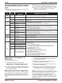
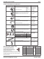
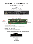
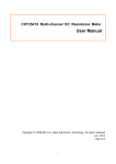
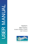
TECH SHEET - DO NOT DISCARD
WARNING
Electrical Shock Hazard
Disconnect power before servicing.
Replace all parts and panels before
operating.
Failure to do so can result in death
or electrical shock.
Electrostatic Discharge (ESD)
Sensitive Electronics
ESD problems are present everywhere. ESD may
damage or weaken the electronic control assembly.
The new control assembly may appear to work well
after repair is finished, but failure may occur at a
later date due to ESD stress.
■
■
■
■
Use an anti-static wrist strap. Connect wrist
strap to green ground connection point or
unpainted metal in the appliance - OR - touch
your finger repeatedly to a green ground
connection point or unpainted metal in the
appliance.
Before removing the part from its package, touch
the anti-static bag to a green ground connection
point or unpainted metal in the appliance.
Avoid touching electronic parts or terminal
contacts; handle electronic control assembly by
edges only.
When repackaging failed electronic control
assembly in anti-static bag, observe above
instructions.
DIAGNOSTICS
Is oven in “Sabbath Mode”? If so, “SAB” will appear in
digital display. Press and hold “6” key for 5 seconds to
end Sabbath Mode.
Disconnect power and perform the following checks:
■
■
■
■
The most common cause for control failure is
corrosion on connectors. Therefore, disconnecting
and reconnecting wires will be necessary
throughout the test procedures.
Check all connections before replacing
components, looking for broken or loose wires,
failed terminals, or wires not pressed into
connectors far enough.
All tests/checks should be made with a VOM or
DVM having a sensitivity of 20,000 ohms per volt
DC or greater.
Resistance checks must be made with power cord
unplugged from outlet, and with wiring harness or
connectors disconnected.
PAGE 1
PRECAUTIONS TO BE
OBSERVED BEFORE AND
DURING SERVICING TO
AVOID POSSIBLE
EXPOSURE TO EXCESSIVE
MICROWAVE ENERGY
a. Do not operate or allow the oven to be
operated with the door open.
b. Make the following safety checks on all ovens to
be serviced before activating the magnetron or
other microwave source, and make repairs as
necessary:
1. Interlock Operation
2. Proper Door Closing
3. Seal and Sealing Surfaces
(Arcing, Wear and Other Damage)
4. Damage to or Loosening of
Hinges and Latches
5. Evidence of Dropping or Abuse
c. Before turning on microwave power for any
service test or inspection within the microwave
generating compartments, check the
magnetron, waveguide or transmission line and
cavity for proper alignment, integrity and
connections.
d. Any defective or misadjusted components in the
interlock, monitor, door seal, and microwave
generation, and transmission systems shall
be repaired, replaced, or adjusted by
procedures described in service manual
before the oven is released to the owner.
e. A microwave leakage check to verify
compliance with the Federal performance
standard should be performed on each oven
prior to release to the owner.
f. Do not attempt to operate the oven if the door
glass is broken.
PROBLEM: Bake Temperature Needs
Adjustment
1. Press BAKE pad for 5 seconds. The default
temperature 0° or a previously entered offset
temperature will show in the Temperature Display.
n
Press the BAKE pad to increase the
temperature in 5° F or 3° C increments.
n
Press the BROIL pad to decrease the
temperature in 5° F or 3° C increments.
Maximum offset temperature adjustment is ±35° F
or ±21° C.
2. Press the START pad to save the temperature
adjustment.
FOR SERVICE TECHNICIAN'S USE ONLY
PART NO. 8302004
PAGE 2
TECH SHEET - DO NOT DISCARD
FAILURE/ERROR DISPLAY CODES
■ Upon replacement, immediately return old electronic oven
NOTES:
■ For combo ovens, the failure code is displayed on the side of
■ Always unplug microwave oven or disconnect power before
touching internal parts of the oven!
FAULT
CODE
ERROR
CODE
F0
E0
F1
F2
the display that corresponds to the oven with faulty part
(upper oven = left side of display).
RECOMMENDED REPAIR PROCEDURE
Default F code – no failure
Will only be displayed if user presses and holds the UPPER OFF key for 5 seconds and
there is no pre-existing fault. Press CANCEL to clear display.
E0, E1, &
E2
Electronic control malfunction
Check oven door switch. If OK replace control.
E3, E4, &
E5
Electronic control malfunction
Replace control.
E0 or E1
E0
Keypad keytail not connected
Key held down too long, or key
is shorted
Temperature sensor opened
(lower cavity)
E1
Temperature sensor shorted
(lower cavity)
E2
Temperature sensor opened
(microwave)
E3
Temperature sensor shorted
(microwave)
E3
F3
F5
MEANING OF
FAILURE CODE
control using the mailing label supplied with each new control.
E0
E0
F6
E1
E0
Lower cavity over temperature
while cleaning
Lower cavity over temperature
during cooking
Microwave cavity over
temperature during cooking
Self-clean latch will not lock
E3
Self-clean latch will not unlock
Oven over temperature while
door open and latch lock
Oven over temperature while
door open and latch unlock
E4
Oven over temperature while
door close and latch unlock
E1
E2
F8
1. Check keypad connector for firm connection.
2. Press CANCEL. If error code returns after 60 sec., replace keypad.
1.
2.
3.
4.
1.
2.
3.
4.
Check lower cavity sensor connection.
Measure sensor resistance (1080Ω at 70° F [21° C]. Add 2Ω per degree F).
If resistance is not valid replace sensor.
If sensor resistance and connections are good, then check for welded-closed relays on the
control. If relay is shorted, replace control.
Check microwave sensor connection.
Measure sensor resistance (280kΩ at 70° F [21° C]; 1kΩ at 392° F [200° C]).
If resistance is not valid replace sensor.
If sensor resistance and connections are good, then check for welded-closed relays on the
control. If relay is shorted, replace control.
See F3, Error Code E0, above.
See F3, Error Code E0, above.
See F3, Error Code E2, above.
1. Check the latch assembly: Check latch arm pivot joint, arm/motor connection, plunger
and hook springs.
2. Check the Latch Motor:
- Check for firm electrical connections.
- Disconnect the two wires from the motor and measure the resistance of the motor.
The resistance should be approximately 2450Ω. If the motor is open (∞Ω) or
shorted (0Ω), it should be replaced.
3. Check the Latch Switch:
Disconnect it and use a continuity tester:
- Door latched = switch closed, continuity should read 0Ω.
- Door unlatched = switch open, continuity should read ∞Ω.
4. Check Door Open/Closed Switch:
Disconnect it and use a continuity tester:
- Door closed = switch closed, continuity should read 0Ω.
- Door open = switch open, continuity should read ∞Ω.
5. Check power and element connections.
Fahrenheit (° F) to Celsius (° C)
Conversion
1. Fill a glass measuring cup with 16 oz. (453cc) of tap
water. Stir the thermometer through the water until
the temperature stabilizes.
The default is Fahrenheit (° F).
2. Place the cup of water in the center of the oven.
Operate on HIGH for 60 seconds.
1. Press the BROIL pad for 5 seconds. The
temperature will be displayed in degrees Celsius
indicated by the “C” in the temperature display.
3. Stir the thermometer through the water and record
the maximum temperature.
2. To return the display to degrees Fahrenheit press
the BROIL pad again for 5 seconds. “F” will show in
the temperature display.
4. Subtract the cold water temperature from the hot
water temperature. The normal result should be a
20 - 38° F (11.1 - 21.1° C) rise in temperature.
Microwave Oven Power Output Test
NOTE: Less than a 20° F (11.1° C) temperature rise
may indicate an operating voltage of less than 110 volts
or a low power output from the magnetron. Cooking
time can be adjusted to compensate for either
circumstance. Replace the magnetron only if the water
temperature rise indicates a power output well beyond
the normal result.
The power output of the magnetron can be measured
by the following test: (for accurate results, the line
voltage must be 120 VAC and the oven cavity must be
clean).
PART NO. 8302004
FOR SERVICE TECHNICIAN'S USE ONLY
TECH SHEET - DO NOT DISCARD
PAGE 3
WIRE HARNESS SCHEMATIC
NOTES:
LIGHT
HEATING
ELEMENT
AC DRIVE
MOTOR
SOLENOID
PLUG WITH
FEMALE CONNECTOR
RELAY COIL
ENCLOSED
THERMISTOR
RECEPTACLE WITH
MALE CONNECTOR
RELAY
CONTACTS
OPERATED
BY DOOR
T.O.D. (RESETABLE)
When replacing the electronic control, be sure to attach the cavity select line to
the proper terminal (see “CAVITY SIZE” table below).
Dots indicate connections or splices.
Circuit shown in standby/off mode with microwave oven door and lower oven
door closed.
THERMAL FUSE/T.O.D.
(NON-RESETABLE ONE TIME)
GROUND (CHASSIS)
BR
ELECTRONIC CONTROL
N L1
DOOR
SW
BK
20A
FUSE
BK BK
J1-1
15A
FUSE
P8-2
CAVITY
T.O.D.
TAN
BR
BK
R
PRIMARY
BU
INTERLOCK
SWITCH
BK
TO
MONITOR
ELECTRONIC FILTER
WP #4451934
CONTROL
TRANSFORMER
L1
P10-2
t°
P17-8
P17-10
BU/R
R
P14-1
BU/R
W P14-2
BU
TURNTABLE
MAGNETRON FAN
BU
SECONDARY
INTERLOCK
SWITCH
P10-3
Y
P8-3 BR
TEMP SENSOR
1080 W AT 70°F/21.1°C
t°
W
V/W
W
V/W
BU
P9-1
R
P15-5
P15-1
TAN
LATCH SWITCH
(OPERATED BY
MOTOR)
TAN
TAN
BU FROM
CONV FAN GY
PRIMARY
INTERLOCK
SWITCH
CONV - 1500W W
J1-2
CONV. T.O.D.
W
J1-7
BK
GRILL - 1200W
GRILL T.O.D.
R
W
J1-6
W
R
J1-3
W
VT
W
P7-6
P5-8
GY/W
W
UPPER BLOWER
P7-5
P5-9
DOOR LOCK
MOTOR LATCH
LOWER BLOWER
W
P7-3
P5-1
ON LATCH ASSY
BR
BR/W P5-3
DOOR SWITCH
OR
CAVITY SIZE
SELECT
GY
MONITOR
SWITCH
GY
BR
W
J1-4
Y
RETURN LINE
MUST BE CONNECTED
TAN
P8-4
P9-3
MAGNETRON
900W OUTPUT
W W
Y
AIR VENT
SOLENOID
120 VAC
MICROWAVE
BK
BR
GY
0.6A
LOWER OVEN
R
R
P10-4
Y
CONVECTION
TEMP SENSOR
280k W AT 70°F/21.1°C
W
BU
W
N
HALOGEN
MICROWAVE
CAVITY LIGHT
R
R
P8-1
GND N L2
R
R
MAGNETRON
T.O.D.
P10-1
Y
P17-1
Y
P17-2
TAN
P17-3
TAN
P17-4
VT
P17-5
VT
BK P17-6
N
LIGHT POWER SUPPLY
BK
J1-5
INCANDESCENT
15W/BULB
BK W BK W
BK
W
P7-2
BU
TAN
CAVITY SIZE
TAN
Y 30"
OPEN
27"
BU/W
Y
BK
W
OR/W
P5-6
P7-7
P5-10
CONV. FAN
W/BK
P7-1
R
BK
BAKE - 2000W
R
R/W
P2-4
OR
BROIL - 3000W
OR
P3-1
P3-2
OVEN
SHUTDOWN
THERMAL
FUSE
R
R
DLB RELAY
RELAY LOGIC MICROWAVE OVEN
MODES
RELAY LOGIC KEY
RE
LAY
MA S
G.
GR
ILL
CO
NV
CO
NV
MA FAN
GF
LIG AN
HT
UPP
ER
BLO
W
ER
RELAY LOGIC LOWER OVEN
P5-7
GN
RELAY
CONTACT
R/W
P2-3
BK
W
W/BK
P7-8
MICRO. FULL PWR
MICRO. VAR. PWR
BROIL
MANUAL CRISP
OFF
CONV. QUICK PREHEAT
CONV. COOK
SPEED COOK
FOR SERVICE TECHNICIAN'S USE ONLY
PART NO. 8302004
PAGE 4
TECH SHEET - DO NOT DISCARD
STRIP CIRCUITS
BROIL
(NO MICROWAVE ENERGY)
CLEAN (OVEN)
The following individual circuits are for use in diagnosis.
Before starting diagnosis, check the line voltage
and for blown fuses.
L1
N L2
TAN
DOOR SWITCH ON
LATCH ASSY
BR/W
BR
BAKE AND PREHEAT-BAKE (OVEN)
TAN
P7-6
VT
P7-5
GY/W
W
W/BK
P2-4
R
BK P2-3
R/W
BAKE - 2000W
P3-1
OVEN
SHUTDOWN
OR THERMAL
FUSE
OR
BK P3-2
BU
BU/W
TAN
Y
DOOR LOCK
MOTOR LATCH
P5-3
P7-5
P5-6
VT
UPPER BLOWER
GY/W
R
BK
P7-8
W/BK
P2-4
R
20A
FUSE
P2-3
R
BK
DLB RELAY
P3-2
R/W
BAKE - 2000W
R/W
OVEN
OR SHUTDOWN
OR
THERMAL
FUSE
BROIL - 3000W
GY
R
BK
PRIMARY
INTERLOCK
SWITCH
MONITOR
SWITCH
BR
W
J1-4
TURNTABLE
BK
BK
RELAY
CONTACT
MAGNETRON FAN
BU
BK P10-4
W
P7-1
R
BK
CAVITY
15A
T.O.D.
BK FUSE TAN
R
J1-1
W
W/BK
R
P10-2
DOOR SHOWN
IN CLOSED
POSITION
W
BR
HALOGEN
MICROWAVE
CAVITY LIGHT
R
J1-5
LOWER BLOWER
P3-1
BROIL - 3000W
P10-1
W
P5-10
BK
RELAY
CONTACT
R/W
Y
BK
W
W/BK
R
P7-3
P7-6
TAN
CAVITY SIZE
SELECT
LOWER BLOWER
W
L1
W
BK P7-1
P7-8
OR
TAN
UPPER BLOWER
LIGHT POWER SUPPLY
P5-1
LATCH SWITCH
(OPERATED BY
MOTOR)
N L2
ELECTRONIC CONTROL
N L2
ELECTRONIC CONTROL
ELECTRONIC CONTROL
RETURN LINE MUST BE CONNECTED
L1
PAGE 5
P7-6
VT
P9-3
BU
P9-1
R
UPPER
BLOWER
W
P7-1
R
R
GRILL
T.O.D.
GRILL - 1200W
W
BK
J1-6
W
R
J1-3
DLB RELAY
SPEED COOK (MICROWAVE)
CONVECTION BAKE (OVEN)
N L2
ELECTRONIC CONTROL
L1
P7-7
OR/W
P7-6
VT
W
FULL POWER / VARIABLE
POWER (MICROWAVE)
LIGHT POWER SUPPLY
W
CONV. FAN
W
UPPER BLOWER
P7-5
BK
P10-1 BR
GY/W
P7-1
W
P2-4
BK P2-3
P3-1
BK P3-2
W/BK
R
R/W
R/W
OVEN
OR SHUTDOWN
OR
THERMAL
FUSE
BROIL - 3000W
P10-2
BK P10-4
RELAY
CONTACT
R
R
GY
R
BR
MONITOR
SWITCH
W
TURNTABLE
DLB RELAY
20A
BK FUSE BK
N L2
P8-2
R
R
BU
BK P8-1
SECONDARY
INTERLOCK
SWITCH
MAGNETRON
T.O.D.
P7-6
BK
P7-1
VT
W
W
UPPER
BLOWER
W
VT
PRIMARY
INTERLOCK
SWITCH
J1-4
HIGH VOLTAGE
SYSTEM
900W OUTPUT
CAVITY
15A
T.O.D.
BK FUSE TAN
R
J1-1
ELECTRONIC CONTROL
P7-6
MAGNETRON FAN
BU
DOOR SHOWN
IN CLOSED
POSITION
R
CUSTOM BROIL (OVEN)
L1
R
HALOGEN
MICROWAVE
CAVITY LIGHT
J1-5
W
W/BK
BAKE - 2000W
R
BK
L1
LOWER BLOWER
P7-8
N
ELECTRONIC CONTROL
UPPER BLOWER
P7-5
BK
W
LOWER BLOWER
P7-8
P3-1
BK
GY/W
P7-1
W/BK
OR
W
W/BK
OR
R/W
P3-2
BROIL - 3000W
OVEN
SHUTDOWN
THERMAL
FUSE
RELAY
CONTACT
R
CONVECT (MICROWAVE)
MANUAL CRISP
(MICROWAVE)
W
BK
20A
FUSE
BK
BK
15A
FUSE
N L2
ELECTRONIC CONTROL
OR/W
P7-6
VT
W
CONVECTION
TEMP SENSOR
280k Ω @ 70° F/21.1° C
CONV. FAN
W
UPPER BLOWER
P7-5
BK
GY/W
P7-1
P10-2
BK P10-4
PRIMARY
INTERLOCK
SWITCH
BU/R
t°
P3-1
BK P3-2
OR
OR
R/W
BROIL - 3000W
R/W
OVEN
SHUTDOWN
THERMAL
FUSE
PART NO. 8302004
MAGNETRON FAN
BU
P10-3
W
BU/R
P14-1
P14-2
GY
BR
GY
MONITOR
SWITCH
W
TURNTABLE
J1-4
GY
AIR VENT
SOLENOID 120 VAC
BR
P8-4
CONV. T.O.D. CONV - 1500W
VT
P7-1
R
P9-3
BU
P9-1
R
J1-2
W
P8-3
P7-6
BK
R
CONV FAN
Y
R
W
RELAY
CONTACT
Y
Y
GY
W/BK
R
R
W
W/BK
R
BK
LOWER BLOWER
P7-8
BK
BR
HALOGEN
MICROWAVE
CAVITY LIGHT
J1-5
CAVITY
T.O.D.
R
TAN
J1-1
P7-7
P10-1
DOOR SHOWN
IN CLOSED
POSITION
DLB RELAY
CONVECTION BROIL (OVEN)
L1
LIGHT POWER SUPPLY
L1
R
R/W
N L2
ELECTRONIC CONTROL
BR
W
J1-7
UPPER BLOWER
GRILL
T.O.D.
BK
R
W
GRILL - 1200W
W
J1-6
J1-3
W
R
DLB RELAY
FOR SERVICE TECHNICIAN'S USE ONLY
PART NO. 8302004
PAGE 6
COMPONENTS
TECH SHEET - DO NOT DISCARD
FRONT/TOP/REAR
SERVICEABLE
CAN BE TESTED
AT CONTROL PANEL
CHECK
POINTS
RESULTS
Electronic Control
Front
—
—
Electronic Filter
Front
—
—
Control Transformer
Front
—
—
DBL Relay
Front
—
—
Membrane Switch
Front
—
—
Incandescent Light
Light Bulb - Front
Light Assy. - Rear
—
—
Latch Switch
Front
P5-6 (BU/W) to
P5-1 (TAN)
Door Unlocked =
Open Circuit
Door Locked =
Closed Circuit
Latch Motor
Front
P7-3 (Y) to Neutral (W)
Approx. 2450 Ω
Door Switch
Front
P5-3 (BR/W) to
P5-1 (TAN)
Door Closed =
Closed Circuit
Door Open =
Open Circuit
Oven Temperature
Sensor
Front
P5-8 (V/W) to
P5-9 (V/W)
1080 Ω @ 70°F
Lower Console
Blowers
Rear
P7-5 (GY/W) to
Neutral (W)
14 Ω to 18 Ω
Oven Shutdown
Thermal Fuse
Rear
P2-4 (R) or P3-1
(OR)
to Red/White
Wire at DLB
Relay
Closed Circuit
Convection Fan
Motor (Lower Oven)
Rear
P7-7 (OR/W) to
Neutral (W)
18 Ω
Bake Element
Rear
P2-4 (R) to
Red/White Wire
at DLBRelay
25 Ω to 30 Ω
Broil Element
Front
P3-1 (OR) to
Red/White Wire
at DLBRelay
17 Ω to 20 Ω
Primary
Winding
40 Ω to 45 Ω
Secondary
Winding
Less than 1 Ω
Light Bulb - Front
Light Assy. - Rear
—
—
Upper Blower (M/W)
Rear
P7-6 (VT) to Neutral (W)
10 Ω to 15 Ω
Convection
Motor/Fan (M/W)
Rear
P10-3 (Y) to Neutral (W)
44 Ω
All Other Microwave
Components
Rear
—
—
Microwave Light
Transformer (M/W)
Halogen Light
(M/W)
Rear
COMPONENTS LOCATIONS
Electronic Control
(Behind Front
Panel)
Tech
Sheet
Blower Motor
Electronic
Filter
(mounted on
Terminal Block
L1 and Neutral)
DBL Relay
Membrane
Switch
20 amp
Microwave Fuse
MW Light
Transformer
Control Transformer
Grill Element Halogen Convection Convection Fan
Light
Assembly
Fan Motor
Thermal
and Element
Fuse
Air Pressure
Cavity
on Back
Relief Valve and
Thermal Fuse
Secondary
Grill
Interlock Switch
Thermal Fuse
Rectifier
15-Amp
Line Fuse
Turntable
Motor
High Voltage
Capacitor
Monitor
Interlock Switch
Primary
Interlock Switch
Cooling Fan Motor
Magnetron
Thermal Fuse
Air Vent
Solenoid
High Voltage
Transformer
Magnetron
Lower Blower
Motor
Oven
Temperature
Sensor
(Rear Panel)
Incandescent
Lights
(Rear Panel)
Door Latch
Assembly
(Latch and
Latch Motor)
Convection
Fan Motor
Oven
Shutdown
Thermal Fuse
(Rear Panel)
CONTROL TRANSFORMER
Low Voltage
Transformer
1st
Secondary
2nd
Secondary
Primary
(P17-1) Y
3rd
Secondary
SEC 1
26 VAC
(P17-2) Y
BLK (P17-8)
120 VAC
60 Hz PRIMARY
W (P17-10)
(P17-3) TAN
SEC 2
24 VAC
(P17-4) TAN
(P17-5) V
SEC 3
7.5 VAC
(P17-6) V
PART NO. 8302004
FOR SERVICE TECHNICIAN'S USE ONLY
TECH SHEET - DO NOT DISCARD
PAGE 7
TESTING THE MICROWAVE OVEN COMPONENTS
COMPONENT
HIGH VOLTAGE
TRANSFORMER
MAGNETRON
CAPACITOR
RECTIFIER
TEST PROCEDURE
RESULTS
1. Remove the leads from the terminals.
2. Set the ohmmeter to Rx1 and touch the leads to the terminals.
Primary
Secondary
Filament to Ground
3. Measure resistance (Rx100)
Primary
Filament
1. Remove the leads from the terminals.
2. Set the ohmmeter to Rx1 and touch the leads to the F and FA
terminals.
3. Set the ohmmeter to Rx1k and measure filament to chassis.
1. Remove the leads from the terminals.
2. Set the ohmmeter to Rx1k and touch the leads to the terminals.
Normal = Less than 1 Ω.
Normal = Less than 1 Ω.
Normal = 0 Ω.
Normal = Infinity.
Normal = Infinity.
Normal = approximately 0 Ω.
Normal = Infinity.
Normal = Momentarily
indicates several ohms, and
gradually returns to infinity.
3. Terminal to chassis.
1. Remove the leads from the terminals.
2. Set the ohmmeter to Rx1k and measure forward resistance.
Normal = Infinity.
3. Measure the reverse resistance.
Normal = Infinity.
Abnormal = Continuity.
Normal = Continuity.
Abnormal = Infinity.
FAN MOTOR
NOTE: Some inexpensive meters may show infinity in both directions.
1. Remove the leads from the terminals.
2. Set the ohmmeter to Rx1 and touch the leads to the terminals.
TURNTABLE
MOTOR
1. Remove the leads from the terminals.
2. Set the ohmmeter to Rx1 and touch the leads to the terminals.
1. Remove the leads from the terminals.
2. Set the ohmmeter to Rx1 and touch the leads to the terminals.
Open
Close
Cavity Thermal Fuse
329° F (165° C)
Grill Thermal Fuse
320° F (160° C) 284° F (140° C)
Magnetron
Cavity
Grill and
Magnetron Thermal Fuse
293° F (145° C) 257° F (125° C)
Thermal Convection Fan Thermal
Fuse
Fuse
Thermal Fuses
Convection Fan Thermal Fuse 293° F (145° C) 221° F (105° C)
GRILL ELEMENT
1. Remove the leads from the terminals.
2. Set the ohmmeter to Rx1 and touch the leads to the terminals.
Normal = approximately 25 Ω.
Abnormal = Infinity.
Normal = approximately 25 Ω.
Abnormal = Infinity.
THERMAL FUSES
Bulbs
AIR VENT
SOLENOID
1. Remove the lead from one terminal.
2. Set the ohmmeter to Rx1k and touch the leads to the terminals.
OVEN SHUTDOWN THERMAL FUSE
Normal = Continuity.
Abnormal = Infinity.
Normal = 14 Ω for both bulbs.
Normal = 7 Ω for one bulb.
Abnormal = Infinity.
Normal = approximately 1650 Ω.
Abnormal = Infinity.
Thermal Fuse
Part No.
Opening
Temp. °F
4452223
266°F ± 10°F
Pink/Wht Stripe
4451442
248°F+18°F to 248°F – 0°F
Yellow/Wht Stripe
4450934
338°F ± 11.7°F
4450334
275°F ± 11.7°F
Verify that the oven shutdown thermal fuse is OK.
4450250
320°F ± 11.7°F
To replace this thermal fuse, refer to chart at right for
correct part number.
4450249
302°F ± 11.7°F
Green/Wht Stripe
8300802
230°F+18°F to 230°F – 0°F
Blue/Wht Stripe
The oven shutdown thermal fuse
is located at the back of the oven.
It will shut down the elements if the
temperature at the back of the oven
exceeds component limits.
FOR SERVICE TECHNICIAN'S USE ONLY
Reclose
Marking
Temp. °F (with Black Letters)
Red
–31°F
MAX
Orange/Wht Stripe
Blue
PART NO. 8302004
PAGE 8
TECH SHEET - DO NOT DISCARD
MANUFACTURED UNDER ONE OR MORE OF
THE FOLLOWING UNITED STATES PATENTS:
4,102,322
4,364,589
4,467,184
OTHER PATENTS PENDING
PART NO. 8302004
FOR SERVICE TECHNICIAN'S USE ONLY