1
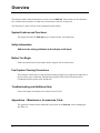
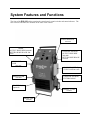
SERVICE MANUAL ECS 350 DUAL SYSTEM FOR Gasoline (Petrol) and Diesel Engines MOTORVAC TECHNOLOGIES INC. ECS350 P/N 200-8252 Rev N/C 2002 Table of Contents Introduction ..........................................................................................................................................iii Overview ................................................................................................................................................v System Features and Functions...................................................................................................... 1-1 Unit Features ................................................................................................................................ 1-1 Control Panel Functions ............................................................................................................... 1-3 Features and Functions................................................................................................................ 1-5 Safety Information............................................................................................................................. 2-1 GASOLINE (Petrol) SYSTEMS: Before You Begin...................................................................................................................... 3-1 First Time Operation ........................................................................................................... 3-1 Mixing Ratios ...................................................................................................................... 3-2 Fuel System Cleaning Procedures.......................................................................................... 4-1 Determining the Vehicle's Fuel System Type ..................................................................... 4-1 Carburetor Setup Procedure............................................................................................... 4-3 Carburetor Cleaning Procedure.......................................................................................... 4-5 Throttle Body Injection (TBI) Setup Procedure................................................................... 4-7 Throttle Body Injection (TBI) Cleaning Procedure .............................................................. 4-9 Port Fuel Injection (PFI) Setup Procedure........................................................................ 4-11 Port Fuel Injection (PFI) Cleaning Procedure................................................................... 4-13 Continuous Injection System (CIS) Setup Procedure....................................................... 4-15 Continuous Injection System (CIS) Cleaning Procedure.................................................. 4-17 DIESEL SYSTEMS: Before You Begin...................................................................................................................... 5-1 First Time Operation................................................................................................................. 5-1 Diesel Fuel System Cleaning Procedures .............................................................................. 6-1 Filling and Mixture Setup .................................................................................................... 6-1 Priming................................................................................................................................ 6-3 Diesel Fuel System Setup Procedure................................................................................. 6-5 Diesel Cleaning Procedure ................................................................................................. 6-8 Trouble Shooting and Additional Help ........................................................................................... 7-1 Electrical Data ............................................................................................................................... 7-2 Appendix A - Maintenance ...............................................................................................................A-1 Maintenance Procedures..............................................................................................................A-1 Replacing the Fuel Filter...............................................................................................................A-1 Maintenance Record ....................................................................................................................A-3 Appendix B - System Accessories..................................................................................................B-1 Basic Adapter Kit (200-3000) .......................................................................................................B-1 Asian / European Applications (200-3009) .................................................................................B-3 Optional Adaptors ........................................................................................................................B-5 Appendix C - Parts ............................................................................................................................C-1 Parts for the ECS 350...................................................................................................................C-1 2002 MotorVac Technologies, Inc. 200-8252 i Introduction Congratulations on your selection of the CARBONCLEAN DUAL SYSTEM. By choosing this product, you are acquiring the most technologically advanced method available for cleaning harmful fuel system contaminants from gasoline engines. The ECS 350 is a self-contained cleaning system, designed to connect to any gasoline or diesel engine (up to 7.3L). Once the unit is connected, it temporarily replaces the regular fuel supply with a mixture of fuel and the specially formulated CarbonClean Cleaning Detergent. With the engine idling, the unit pumps the fuel/detergent mixture through the engine's fuel system. As the mixture passes through the vehicles’ fuel system, it loosens and dissolves accumulated deposits, which then pass harmlessly out through the exhaust system or are removed by the unit’s fuel filter. Removing contaminants from the combustion chamber creates a more even burn of fuel, which improves horsepower, increases fuel economy, and reduces exhaust emissions. Please refer to the chart below for the recommended service intervals: Recommended Service Intervals Type of Vehicle Mileage Automobile - Gasoline Automobile - Diesel Light-Duty Trucks 12,000 – 15,000 miles or 19,000 – 24,000 kilometers or once a year 12,000 – 15,000 miles or 19,000 – 24,000 kilometers or once a year Medium to Heavy-Duty Trucks 60,000 – 100,000 miles or 97,000 – 161,000 kilometers or 1600 to 1800 hours of operation Please study this User Guide to become thoroughly familiar with the ECS 350 before using it. IMPORTANT The ECS 350 Fuel System Machines are designed to work EXCLUSIVELY with CarbonClean Cleaning Detergents. Use of any other chemicals during this process may cause operational failure of the ECS 350 and voids the manufacturer’s warranty. See warranty card for details. 2002 MotorVac Technologies, Inc. 200-8252 ii Overview This manual contains all the information you need to use the ECS 350. Please make sure all technicians have read this manual and have it within easy reach whenever the unit is being used. The following is a quick reference to the information in this manual: System Features and Functions: This chapter describes the ECS 350 gauges, control switches, and connections. Safety Information Adhere to the safety guidelines in this chapter at all times! Before You Begin Follow the instructions for each chapter before using the unit for the first time. Fuel System Cleaning Procedures These chapters contain step-by-step setup and cleaning procedures for using the unit with each of the fuel system types: Carburetor, Throttle Body Injection (TBI), Port Fuel Injection (PFI), Continuous Injection System (CIS) and Diesels. Troubleshooting and Additional Help Turn to this chapter for machine service data for the ECS 350. Appendices – Maintenance, Accessories, Parts. The appendices contain routine maintenance procedures for the ECS 350, such as changing the fuel filters, etc. 2002 MotorVac Technologies, Inc. 200-8252 iii System Features and Functions The front of the ECS 350 cabinet contains the control panel, control switches and status indicators. The fuel reserviors and filters are mounted on the sides of the cabinet. POWER HARNESS 020-0030 DIESEL OUTPUT HOSE-RED 200-0400 RETURN HOSE-BLACK 2000300 GASOLINE (PETROL) OUTPUT HOSE-RED 200-0400 RETURN HOSE-BLACK 200-0300 DIESEL FUEL TANK 200 1022 GASOLINE (PETROL) FUEL TANK 200-1022 DIESEL FILTER GASOLINE (PETROL) FILTER 050-0095 050-0095 DRAWERS (4) (Optional) WHEEL – 8” Dia 010-0027 FRONT LEG 010-0300 ECS 350 Control Panel Functions CONTROL PANEL ASSEMBLY 200-8088 DIESEL PRESSURE GAUGE START/RUN SWITCH 020-1201 AMBER LAMP ON/OFF SWITCH GASOLINE (PETROL) PRESSURE GAUGE SERVICE SELECTOR SWITCH 020-1200 GREEN LAMP TIMER 020-0153 GASOLINE (PETROL) PRESSURE REGULATOR ECS 350 Features and Functions Descriptions of the gauges, control switches, and status indicators making up the control panel are listed below. Please become familiar with these features and functions before using the unit. Adjust Time Knob Sets or re-sets the system run time in one-minute increments, from 1 to 60 minutes. Service Selector Switch Selects fuel type: Diesel or Gasoline Start/Run Switch (Momentary) Starts the cleaning cycle. Run Cycle Light (green) Illuminates when the run cycle is under way. On / Off Switch Shuts off power to the unit. On / Off Light (orange) Illuminates when switch is on. Fuel Pressure Gauge Displays output pressure of the unit’s output hose. Pressure Adjust Regulator Used to adjust the gasoline (petrol) system pressure during the cleaning process. Turn clockwise to close (increase the pressure); counterclockwise to open (decrease the pressure). Warning Alarm Sounds until pump builds pressure, or when the run cycle is complete or when a pressure loss occurs. Output Hose (red) Connects to the input side of the vehicle's engine fuel system. Return Hose (black) Connects to the return side of the vehicle's engine fuel system. Fuel Filter Filters out contaminants that become removed during the cleaning process. See Appendix for replacement information Battery Cables Positive (red) and negative (black) battery connections (12 VOLTS DC) Circuit Breaker 15 Ampere circuit breaker for pump Fuel Tanks (2) Holds up to 2 liters (70oz.) per tank Safety Information and Precautions /!\ DANGER Vehicle exhaust gases contain Carbon Monoxide, which is a colorless and odorless lethal gas. Only run engines in well-ventilated areas and avoid breathing exhaust gases. Extended breathing of exhaust gases will cause serious injury or death. /!\ WARNING Exhaust gases, moving parts, hot surfaces, and potent chemicals are present during the use of the fuel system cleaner. Read and understand the operator’s manual before using the fuel system cleaner. When using chemicals always refer to the MSDS sheets and manufacturer’s instructions for the proper procedure to handle emergency medical treatment, cleanup, handling and storage requirements. Improper use of the fuel system cleaner or exposure to exhaust gases or cleaning chemicals can cause injury. Flammable fuel chemical and vapors can ignite. Avoid exposure to flames, sparks, hot engine parts, and other ignition sources. Always keep fully charge fire extinguisher nearby. The extinguisher should have a class B rating and be suitable for gasoline, chemical, and electrical fires. Cleanup any fuel or chemical spills immediately. Dispose of contaminated cleanup material according to governing environmental laws. Never look directly into the air induction plenum or carburetor throat when the engine is operating. Always plug or cap any open fuel lines during service. Keep Cleaner and Detergent container closed except when filling reservoir. Explosion or flame or exposure to flammable liquid and vapors can cause injury. Flammable liquid can splash out of reservoir when pump is on and/or unit is being moved. Always keep Reservoir Cap secure except when filling reservoir. Explosion or flame can cause injury. Many fuel systems maintain residual pressure in fuel lines even after the engine has been turned off. Wear safety goggles. Wear chemical resistant gloves when connecting or disconnecting fitting and adaptors. Obtain ZERO psi before connecting or disconnecting any fuel lines or adaptors. Explosion or flame or exposure to flammable liquid and vapors can cause injury. Chemicals can cause harmful byproducts. Use only approved chemicals (refer to operator’s manual). Do not swallow or ingest any chemicals. Use with adequate ventilation. Avoid breathing vapors. Do not store chemicals on or in the machine. Improper use of chemicals can cause injury. Over exposure can have harmful effect on eyes, skin, respiratory system and possible unconsciousness and asphyxiation. Improperly blocked vehicles can move. Set the parking brake and chock the wheels. Moving vehicles can cause injury. Moving engine parts. The engine cooling fan will cycle on and off depending on the coolant temperature and could operate without the engine running. Wear safety goggles. Always keep objects, clothing, and hands away from the cooling fans and engine parts. Moving engine parts can cause injury. Hot surfaces are present during and after running the engine. Do not contact hot surfaces such as, manifolds, pipes, mufflers, catalytic converters or radiators and hoses. Hot surfaces can cause injury. Catalytic converters become extremely hot. Do not park a converter-equipped vehicle over dry grass, leaves, paper, or any other flammable material. Do not touch a catalytic converter until the engine has been off for at least 45 minutes. For tests allowing unburned hydrocarbons or service involving operation of an overly rich condition, minimize the time of rich operation, monitor the catalytic converter temperature, and allow at least two minutes of operation at normal mixture subsequent to testing or service for converter cooling. Catalytic converters can cause burns. Cracked fan blades can become airborne. Examine fan blades for cracks. If found, do not service the vehicle. Flying objects can cause injury. See next page Batteries produce explosive gases and can explode. Wear safety goggles when working on or near batteries. Use in a well-ventilated area. Keep sparks and flames away from the battery and never lay tools, equipment or other conductive objects on the battery. When tools or equipment is connected to the battery, make sure the equipment power switch is off. Connect the positive lead of the equipment to the positive lead of the battery first; connect the negative lead of the equipment to a solid ground point as far from the battery as possible. Keep battery acid away from skin or eyes. In case of eye contact, flush with clean water for 15 minutes and get medical attention. Battery explosion and ignited gases can cause injury. Before You Begin First Time Operation-GASOLINE/PETROL OPERATION NOTE The following process is used to flush factory testing fluids out of your new machine, and is only necessary before the first time you use the unit. 1. Verify that the fuel filter is connected and securely in place on the side of the cabinet. 2. Check the output/return hoses, battery connections, and all external components for damage. 3. Turn the Gasoline (Petrol) PRESSURE REGULATOR on the unit’s control panel counterclockwise until it is completely open. 4. Attach the unit to the vehicle's battery by connecting the red battery clip to the positive (+) battery terminal and the black battery clip to a solid ground point as far from the battery as possible. Press the SERVICE SELECTOR switch to the side with Gasoline (Petrol) FUEL SYSTEM SERVICE. 5. Fill the reservoir on the right side with clean gasoline (petrol) until the tank level indicates 1/4 tank. See notes on page 3-2 and figure 3-3 for alternate filling procedure. 6. Connect the output (red) hose and return (black) hose together by using the #060-1400 adaptors and securing them with a clamp. Follow the procedures below to flush fuel through the system: • • • • • • Set SERVICE SELECTOR to gasoline (petrol) SERVICE SYSTEM. Set the TIMER knob for five minutes. Press the ON/OFF switch to the on position. NOTE: Alarm will sound continually until pump starts. Press and hold the START/RUN switch for five minutes. Release the START/RUN switch. Turn off the ON/OFF switch. 7. Disconnect the output and return lines. 8. Connect the #060-1400 adaptor to the output hose, then drain the gasoline from the reservoir using the following procedure: • • • • • • • 9. Set the TIMER knob for five minutes. Direct the output (red) hose into an appropriate container. Press the ON/OFF switch to the on position. NOTE: Alarm will sound continually until pump starts. Press and hold the START/RUN switch until the fuel from the unit has been emptied into the container. Release the START/RUN switch. Turn off the ON/OFF switch. Dispose of the fuel in an environmentally approved method. The reservoir is now completely drained of fuel. Follow the steps below before performing the first cleaning service: Mixing Ratios Using a separate container or the ECS 350 reservoir, follow the chart below to mix the proper amounts of CarbonClean Cleaning Detergent for Gasoline and fuel for the cleaning process. NOTE: See page 3-3, when utilizing tee adapter 060-4500 for alternate filling procedure. Always have the ball valve on tee adapter closed until ready to fill reservoir while using the vehicles fuel pump. After connecting all hoses, start engine. Check all connections for leaks. Partially open ball valve just enough to allow gasoline (petrol) to flow into reservoir and not have the engine die. NOTE: The proper ratio is 1 oz. (30 ml.) per cylinder to 3 oz. (90 ml.) gasoline. DETERGENT / GASOLINE (PETROL) RATIO 3 cylinders = 3 oz. (90 ml.) detergent to 9 oz. (270 ml.) gasoline, (360 TOTAL) 4 cylinders = 4 oz. (120 ml.) detergent to 12 oz. (360 ml.) gasoline, (480 TOTAL) 5 cylinders = 5 oz. (150 ml.) detergent to 15 oz. (450 ml.) gasoline, (600 TOTAL) 6 cylinders = 6 oz. (180 ml.) detergent to 18 oz. (540 ml.) gasoline, (720 TOTAL) 8 cylinders = 8 oz. (240 ml.) detergent to 24 oz. (720 ml.) gasoline, (960 TOTAL) 10 cylinders = 10 oz. (300 ml.) detergent to 30 oz. (900 ml.) gasoline, (1200 TOTAL) 12 cylinders = 12 oz. (360 ml.) detergent to 36 oz. (1080 ml.) gasoline, (1440 TOTAL) Filling Reservoir Procedure FIGURE A- CARBURETOR FILLING THIS METHOD IS ALSO TYPICAL FOR RETURNLESS / SINGLE LINE FUEL INJECTION SYTEMS. 060-4500 FIGURE ATHIS METHOD TYPICAL FOR ALL TWO LINE INJECTION SYSTEMS. SEE NOTE: PAGE 3-2. 060-4500 Fuel System Cleaning Procedures-GAS Determining the Vehicle's Fuel System Type It is very important to determine the fuel system type of the vehicle to be serviced before performing any setup or cleaning procedure on the vehicle. The unit can be used with any of the four different types of gasoline fuel systems listed below: Carburetion Carburetors come in a variety of sizes and shapes. These can be easily identified by locating the choke plate in the air horn. Throttle Body Injection (TBI) Throttle bodies are centrally mounted, as are carburetors, and use one or two electronic injectors. Port Fuel Injection (PFI) This system uses a single electronic injector per cylinder, mounted so that fuel spray is directed into the intake port. Continuous Injection System (CIS) A Continuous Injection System is easily identified by noting the fuel distributor and the solid steel or flex steel lines running from the fuel distributor to each individual injector. The fuel distributor controls the amount of fuel sprayed into the intake port while the injectors control the opening and closing pressure. NOTE Once you have determined the fuel system type, turn to the appropriate section in this chapter for instructions on how to perform the fuel line setup and cleaning procedure for that system. Carburetor Setup Procedure Follow the steps below to connect the unit to the vehicle's fuel system. Make sure the vehicle has at least 1/8 tank of fuel before beginning this process. 1. Start the vehicle and allow the engine to reach normal operating temperature. IMPORTANT Do not perform the setup or cleaning process if the vehicle’s engine oil or coolant level is low. If necessary, add oil and/or coolant to the vehicle. 2. Turn the vehicle OFF when normal operating temperature has been reached. 3. Turn the Gasoline (Petrol) PRESSURE REGULATOR counterclockwise until the regulator is completely open. Verify that the ON/OFF switch is turned off. 4. Attach the unit to the vehicle's battery by connecting the red battery clip to the positive (+) battery terminal and the black battery clip to a solid ground point as far from the battery as possible. Press the SERVICE SELECTOR switch to the side with Gasoline (Petrol) FUEL SYSTEM SERVICE. 5. Remove the vehicle's gas cap to relieve fuel tank pressure. 6. Disconnect the vehicle’s fuel line at the carburetor inlet or at the fuel pump outlet. There should now be two open ends to work with: • One coming from the fuel pump. • One going into the carburetor. 7. Add a pre-mixed gasoline and detergent mixture to the right side (gasoline /petrol) reservoir. When filling the reservoir, add 1 oz. (30 ml.) of Detergent to 3 oz. (90 ml.) gasoline per cylinder . See page 3-3 for alternate filling method (Refer to page 3-2 for the proper ratios.) SEE NEXT PAGE /!\ WARNING Flammable Liquid can squirt out of pressurized lines when connecting or disconnecting. Wear Safety goggles. Obtain ZERO pressure before connecting or disconnecting any fuel lines or adaptors. Wear chemical resistant gloves when connecting or disconnecting fittings and adaptors. Wrap shop towel around pressure fittings and adaptors when disconnecting. Avoid exposure to flames, sparks, hot engine parts, and other ignition sources. Explosion or flame or exposure to flammable liquid and vapors can cause injury. 8. As shown in the figure below, connect the ECS 350 output (red) hose to the inlet of the carburetor and block / deadhead the fuel line coming from the vehicle’s fuel pump. You are now ready to perform the carburetor cleaning procedure. Carburetor Cleaning Procedure Follow the steps below to circulate the fuel/detergent mixture through the vehicle's carburetor. 1. Verify that Carburetor Setup Steps 1- 8 above have been completed. 2. Refer to the vehicle's service manual for the manufacturer's recommended pressure. 3. Adjust TIMER knob for 30 minutes. (Run time may be adjusted depending on the condition of the vehicle’s fuel system.) 4. Press the ON/OFF switch on . 5. Press and hold the START/RUN switch. 6. Turn the Gasoline (Petrol) PRESSURE REGULATOR clockwise until the Fuel PRESSURE gauge reads 4 PSI, or the equivalent of the manufacturer's recommended specifications. 7. Release the START/RUN switch. Check all connections for leaks. 8. Start the vehicle to begin the fuel system cleaning process. • When the cleaning process is halfway completed, step on the vehicle’s accelerator quickly three or four times. Then, maintain 1500 – 2000 RPM for 30 seconds. 9. When the run time expires, the cleaning is complete. The unit will automatically shut off and the alarm will sound. Press off the ON/OFFswitch. 10. Turn OFF the vehicle's engine. 11. Turn the Gasoline (Petrol) PRESSURE REGULATOR counterclockwise on the unit to release any residual pressure. IMPORTANT Wrap a shop towel around pressure fittings before disconnection to protect against residual fuel spray. 12. Disconnect the battery leads, hoses, and adaptors. Return the vehicle's fuel system to its normal operating condition by re-connecting the vehicle's fuel lines. SEE NEXT PAGE 13. Re-install the vehicle's gas cap. 14. Start the vehicle and verify that there are no leaks. 15. Test drive the vehicle for five kilometers (3 miles) immediately following the cleaning service to flush all detergent from the vehicle's fuel and exhaust systems. Throttle Body Injection (TBI) Setup Procedure Follow the steps below to connect the unit to the vehicle's fuel system. Make sure the vehicle has at least 1/8 tank of fuel before beginning this process. 1. Start the vehicle and allow the engine to reach normal operating temperature. IMPORTANT Do not perform the setup or cleaning process if the vehicle’s engine oil or coolant level is low. If necessary, add oil and/or coolant to the vehicle. 2. Turn the vehicle OFF when normal operating temperature has been reached. 3. Turn the Gasoline (Petrol) PRESSURE REGULATOR counterclockwise until the regulator is completely open. Verify that the ON/OFF switch is turned off. 4. Attach the unit to the vehicle's battery by connecting the red battery clip to the positive (+) battery terminal and the black battery clip to a solid ground point as far from the battery as possible. Press the SERVICE SELECTOR switch to the side with Gasoline (Petrol) FUEL SYSTEM SERVICE. 5. Remove the vehicle's gas cap to relieve fuel tank pressure. 6. Disconnect the vehicle’s fuel lines from the throttle body. There are now four open ends to work with: Pressure Line From the tank to the throttle body. 7. Return Line From the throttle body to the tank. Add a pre-mixed gasoline and detergent mixture to the right side (gasoline /petrol) reservoir. When filling the reservoir, add 1 oz. (30 ml.) of Detergent to 3 oz. (90 ml.) gasoline per cylinder . See page 3-3 for alternate filling method (Refer to page 3-2 for the proper ratios.) /!\ WARNING Flammable Liquid can squirt out of pressurized lines when connecting or disconnecting. Wear Safety goggles. Obtain ZERO pressure before connecting or disconnecting any fuel lines or adaptors. Wear chemical resistant gloves when connecting or disconnecting fittings and adaptors. Wrap shop towel around pressure fittings and adaptors when disconnecting. Avoid exposure to flames, sparks, hot engine parts, and other ignition sources. Explosion or flame or exposure to flammable liquid and vapors can cause injury. 8. As shown in the figure below, connect one end of the loop adaptor (#060-2501) to the pressure line coming from the vehicle's fuel tank. Connect the other end of the loop adaptor (#060-2501) to the return line going back to the fuel tank. This forms a tank-to-tank loop, making it unnecessary to disconnect the fuel pump. 9. As shown in the figure above, connect the output (red) hose from the unit to the adaptor on the pressure line going into the TBI unit. 10. As shown in the figure above, connect the return (black) hose from the unit to the adaptor on the return line coming from the TBI unit. You are now ready to perform the TBI cleaning procedure. Throttle Body Injection (TBI) Cleaning Procedure Follow these steps to circulate the cleaning mixture through the TBI unit to clean the throttle body, injector screens, and pressure regulator. 1. Verify that TBI Setup Steps 1-10 above have been completed before continuing. 2. Refer to the vehicle's service manual for the manufacturer's recommended pressure. 3. Adjust TIMER knob for 10 minutes. Press the ON/OFF switch on . 4. Press and hold the START/RUN switch until pressure builds. 5. Turn the Gasoline (Petrol) PRESSURE REGULATOR clockwise until closed. While in the recirculating mode, the TBI unit is being cleaned, and the particles are filtered through the unit’s filter. 6. Check all connections for leaks. • Make a note of the fuel pressure reading; this is the true opening pressure of the vehicle’s pressure regulator without vacuum assist when the engine is at normal operating temperature. • NOTE: By turning the Gasoline (Petrol) PRESSURE REGULATOR in and out and “PULSING” the mixture from time to time, the cleaning process will be enhanced in this mode. 7. After the 10 minutes has expired adjust Timer knob for an additional 30 minutes. (Run time may be adjusted depending on the condition of the vehicle’s fuel system.) 8. Press the START/RUN switch. 9. Start the vehicle to begin the fuel system cleaning process. 10. When the run time expires, the cleaning is complete. The unit will automatically shut off and the alarm will sound. Press off the ON/OFF switch. 11. Turn OFF the vehicle's ignition. 12. Turn the Gasoline (Petrol) PRESSURE REGULATOR counterclockwise on the unit to open it and release residual pressure. IMPORTANT Wrap a shop towel around pressure fittings before disconnection to protect against residual fuel spray. 13. Disconnect the battery leads, hoses, and adaptors. Return the vehicle's fuel system to its normal operating condition by re-connecting the vehicle's fuel lines. 14. Re-install the vehicle's gas cap. 15. Start the vehicle and verify that there are no leaks. 16. Test drive the vehicle for five kilometers (3 miles) immediately following the cleaning service to flush all detergent from the vehicle's fuel and exhaust systems. Port Fuel Injection (PFI) Setup Procedure Follow the steps below to connect the unit to the vehicle's fuel system. Make sure the vehicle has at least 1/8 tank of fuel before beginning this process. 1. Start the vehicle and allow the engine to reach normal operating temperature. IMPORTANT Do not perform the setup or cleaning process if the vehicle’s engine oil or coolant level is low. If necessary, add oil and/or coolant to the vehicle. 2. Turn the vehicle OFF when normal operating temperature has been reached. 3. Turn the Gasoline (Petrol) PRESSURE REGULATOR counterclockwise until the regulator is completely open. Verify that the ON/OFF switch is turned off. 4. Attach the unit to the vehicle's battery by connecting the red battery clip to the positive (+) battery terminal and the black battery clip to a solid ground point as far from the battery as possible. Press the SERVICE SELECTOR switch to the side with Gasoline (Petrol) FUEL SYSTEM SERVICE. 5. Remove the vehicle's gas cap to relieve fuel tank pressure. 6. Disconnect the fuel lines from the fuel rail. There are now four open ends to work with: Pressure Line Return Line From the fuel tank to the fuel rail. From the fuel rail to the fuel tank. 7. Add a pre-mixed gasoline and detergent mixture to the right side (gasoline /petrol) reservoir. When filling the reservoir, add 1 oz. (30 ml.) of Detergent to 3 oz. (90 ml.) gasoline per cylinder . See page 3-3 for alternate filling method (Refer to page 3-2 for the proper ratios.) /!\ WARNING Flammable Liquid can squirt out of pressurized lines when connecting or disconnecting. Wear Safety goggles. Obtain ZERO pressure before connecting or disconnecting any fuel lines or adaptors. Wear chemical resistant gloves when connecting or disconnecting fittings and adaptors. Wrap shop towel around pressure fittings and adaptors when disconnecting. Avoid exposure to flames, sparks, hot engine parts, and other ignition sources. Explosion or flame or exposure to flammable liquid and vapors can cause injury. 8. As shown in the figure below, connect one end of the loop adaptor (#060-2501) to the pressure line coming from the vehicle's fuel tank. Connect the other end of the loop adaptor (#060-2501) to the return line going back to the fuel tank. This forms a tank-to-tank loop, making it unnecessary to disconnect the fuel pump. 9. As shown in the figure above, connect the output (red) hose from the unit to the adaptor on the pressure line going into the fuel rail. As shown in the figure above, connect the return (black) hose from the unit to the adaptor on the return line coming from the fuel rail. 10. You are now ready to perform the PFI cleaning procedure. Port Fuel Injection (PFI) Cleaning Procedure Follow these steps to circulate the cleaning mixture through the Port Fuel Injection unit to clean the fuel rail, injector screens, and pressure regulator. 1. Verify that PFI Setup Steps 1-10 above have been completed before continuing. 2. Refer to the vehicle's service manual for the manufacturer's recommended pressure. 3. Adjust TIMER knob for 10 minutes. Press the ON/OFF switch on. 4. Press and hold the START/RUN switch. 5. Turn the Gasoline (Petrol) PRESSURE REGULATOR clockwise until the PRESSURE GAUGE reads past 4 PSI. The pump will remain on. 6. Release the START/RUN switch and continue to turn the Gasoline (Petrol) PRESSURE REGULATOR clockwise until it is completely closed. This will clean the PFI unit, injector screens, fuel rail, and pressure regulator while filtering contaminants through the unit’s filter. Check all connections for leaks. • Make a note of the fuel pressure reading; this is the true opening pressure of the vehicle's pressure regulator without vacuum assist when the engine is at normal operating temperature. • NOTE: By turning the Gasoline (Petrol) PRESSURE REGULATOR in and out and “PULSING” the mixture from time to time, the cleaning process will be enhanced. 7. After the 10 minutes has expired, adjust TIMER to 30 minutes. (Run time may be adjusted depending on the condition of the vehicle’s fuel system.) 8. Press the START/RUN switch. 9. Start the vehicle to begin the fuel system cleaning process. 10. When the run time expires, the cleaning is complete. The unit will automatically shut off and the alarm will sound. Press off the ON/OFF switch. 11. Turn OFF the vehicle's ignition. 12. Turn the Gasoline (Petrol) PRESSURE REGULATOR counterclockwise on the unit to release any residual pressure. IMPORTANT Wrap a shop towel around pressure fittings before disconnection to protect against residual fuel spray. 13. Disconnect the battery leads, hoses, and adaptors. Return the vehicle's fuel system to its normal operating condition by re-connecting the vehicle's fuel lines. 14. Re-install the vehicle's gas cap. 15. Start the vehicle and verify that there are no leaks. 16. Test drive the vehicle for five kilometers (3 miles) immediately following the cleaning service to flush all detergent from the vehicle's fuel and exhaust systems. Continuous Injection System (CIS) Setup Procedure Follow the steps below to connect the unit to the vehicle's fuel system. Make sure the vehicle has at least 1/8 tank of fuel before beginning this process. 1. Start the vehicle and allow the engine to reach normal operating temperature. IMPORTANT Do not perform the setup or cleaning process if the vehicle’s engine oil or coolant level is low. If necessary, add oil and/or coolant to the vehicle. 2. Turn the vehicle OFF when normal operating temperature has been reached. 3. Turn the Gasoline (Petrol) PRESSURE REGULATOR counterclockwise until the regulator is completely open. Verify that the ON/OFF switch is turned off. 4. Attach the unit to the vehicle's battery by connecting the red battery clip to the positive (+) battery terminal and the black battery clip to a solid ground point as far from the battery as possible. Press the SERVICE SELECTOR switch to the side with Gasoline (Petrol) FUEL SYSTEM SERVICE. 5. Remove the vehicle's gas cap to relieve fuel tank pressure. 6. Disconnect the vehicle’s fuel lines from the fuel distributor. There are now four open ends to work with: Pressure Line From the fuel tank to the fuel distributor. 7. Return Line From the fuel distributor to the fuel tank. Add a pre-mixed gasoline and detergent mixture to the right side (gasoline /petrol) reservoir. When filling the reservoir, add 1 oz. (30 ml.) of Detergent to 3 oz. (90 ml.) gasoline per cylinder . See page 3-3 for alternate filling method (Refer to page 3-2 for the proper ratios.) /!\ WARNING Flammable Liquid can squirt out of pressurized lines when connecting or disconnecting. Wear Safety goggles. Obtain ZERO pressure before connecting or disconnecting any fuel lines or adaptors. Wear chemical resistant gloves when connecting or disconnecting fittings and adaptors. Wrap shop towel around pressure fittings and adaptors when disconnecting. Avoid exposure to flames, sparks, hot engine parts, and other ignition sources. Explosion or flame or exposure to flammable liquid and vapors can cause injury. 8. As shown in the figure below, connect one end of the loop adaptor (#060-2501) to the pressure line coming from the vehicle's fuel tank. Connect the other end of the loop adaptor (#060-2501) to the return line going back to the fuel tank. This forms a tank-to-tank loop, making it unnecessary to disconnect the fuel pump. 9. As shown in the figure above, connect the output (red) hose from the unit to the adaptor on the pressure line going into the fuel distributor. 10. As shown in the figure above, connect the return (black) hose from the unit to the adaptor on the return line coming from the fuel distributor. You are now ready to begin the CIS cleaning procedure. Continuous Injection System (CIS) Cleaning Procedure Follow the steps below to circulate the cleaning mixture through the CIS fuel distributor to clean the pressure regulator and the top portion of the fuel distributor. 1. Verify that CIS Setup Steps 1-10 above have been completed before continuing. 2. Refer to the vehicle's service manual for the manufacturer's recommended pressure. 3. Adjust TIMER knob for 10 minutes. Press the ON/OFF switch on. 4. Press and hold the START/RUN switch. 5. Turn the Gasoline (Petrol) PRESSURE REGULATOR clockwise until the PRESSURE GAUGE reads past 4 PSI. The pump will remain on. 6. Release the START/RUN switch and continue to turn the Gasoline (Petrol) PRESSURE REGULATOR clockwise until it is completely closed. This will clean the CIS fuel distributor and filter particles through the unit’s filtering system. Check all connections for leaks. • Make a note of the fuel pressure reading; this is the true opening pressure of the vehicle's pressure regulator when the engine is at normal operating temperature. • NOTE: By turning the Gasoline (Petrol) PRESSURE REGULATOR in and out “PULSING” the mixture from time to time, the cleaning process will be enhanced in this mode. 7. After the 10 minutes has expired, adjust TIMER for 30 minutes. (Run time may be adjusted depending on the condition of the vehicle’s fuel system.) 8. Press the START/RUN switch. 9. Start the vehicle to begin the fuel system cleaning process. • When the cleaning process is halfway completed, step on the vehicle’s accelerator quickly three or four times. Then, maintain RPM at 1500 - 2000 for 30 seconds. • If the vehicle is equipped with a Cold Start Injector, you may use a Pulse Tester to energize the Cold Start Injector a few quick times during the run cycle to clean it. WARNING: DO NOT ALLOW CIS VEHICLES TO RUN OUT OF FUEL. TURN OFF THE VEHICLE’S ENGINE BEFORE COMPLETION OF THE RUN CYCLE. 11. The unit will automatically shut off and the alarm will sound when the engine is stopped. Press off the ON/OFF switch. 12. Turn the Gasoline (Petrol) PRESSURE REGULATOR counterclockwise on the unit to release residual pressure. IMPORTANT Wrap a shop towel around pressure fittings before disconnection to protect against residual fuel spray. 13. Disconnect the battery leads, hoses, and adaptors. Return the vehicle's fuel system to its normal operating condition by re-connecting the vehicle's fuel lines. 14. Re-install the vehicle's gas cap. 15. Start the vehicle and verify that there are no leaks. 16. Test drive the vehicle for five kilometers (3 miles) immediately following the cleaning service to flush all detergent from the vehicle's fuel and exhaust systems. Before You Begin-DIESEL SYSTEMS First Time Operation The unit is tested at the factory with special test fluids then completely drained. These test fluids are compatible with diesel engine systems. Because the unit is dry during shipping, it will be necessary to prime the machine before it is put into service. 1. Fill the units fuel filter completely with diesel fuel, approximately 1quart (0.95 L). Verify that the unit’s fuel filter is securely in place on the unit. 2. Check the output/return hoses, battery connections, and all external components. 3. Attach the unit to a vehicle battery by connecting the red battery clip to the positive (+) battery terminal and connect the black battery clip to a solid ground (11-15 Volts DC, 8 amperes at 12VDC). 4. Pour 3 - 16 ounce cans (48 ounces, 1.42L) of Detergent for Industrial Diesel Tune into the unit‘s reservoir, and 1/8 of a gallon (16 ounces, 0.47L) of diesel fuel. See page 6-2, Figure A for alternate filling procedure. 5. Connect the output (red) hose and the return (black) hose to each end of the adaptor (MV P/N 060-4500). Verify ball valve is closed. This will allow the fuel to circulate and fill the system with solution. 6. Switch the ON/OFF switch to the on position. NOTE: Alarm will sound continually until pump starts. 7. Press and hold the START/ON switch, the pump will supply fluid to the output hose. Operate the system in this Prime mode for three minutes, then release START/ON switch, and turn off the ON/OFF switch. Remove the adaptor. The unit should now be primed and ready for service. 8. Disconnect battery connections if unit is not to put into immediate use. The desired ratio is 1:1 - One part cleaning detergent to one part diesel fuel can be added if additional cleaner/fuel solution is needed. When mixing in an external container, measure equal parts cleaner and fuel in a suitable container. Keep container sealed when not in use. NOTE Repeat the above procedures any time the unit’s reservoir and filter are completely drained of fuel, unless filling from a premixed 1:1 ratio of detergent and diesel fuel mixture. Diesel System Cleaning Procedures Filling and Mixture Setup Follow the steps below to obtain the proper fuel mixture for use during the cleaning procedure. Make sure the vehicle has at least 5 gallons (18.9L) of fuel before beginning this process. 1. Start the vehicle. Allow the engine to reach normal operating temperature if possible. NOTE: The diesel engine cleaning system should be operated on a level surface. For best results, engine should be up to operating temperature and fuel filters should be changed prior to service. Check the engine’s oil level and add oil if necessary. DO NOT PERFORM THE CLEANING PROCESS IF THE ENGINE OIL LEVEL IS LOW. Check the coolant and add if necessary. If the engine is hot, check the level of the overflow tank. DO NOT PERFORM (and if necessary, STOP) THE CLEANING PROCESS IF THE ENGINE IS OVERHEATING. 2. Turn the engine OFF when normal operating temperature has been reached. 3. Remove the units diesel reservoir cap, and add the Detergent for Industrial Diesel Tune to the system’s reservoir. The desired ratio is 1:1 - One part cleaning detergent to one part diesel fuel. (Use 4oz. (118ml) diesel detergent per 1 liter engine size) Note: It is recommended that a full tank mixture should be used when working with engines that utilize electronically operated injectors. 4. To add diesel fuel to the system’s reservoir using the 060-4500 adapter, see page 6-2, FIGURE A. Reinstall tank cap onto reservoir, but leave cap slightly loose during the service. IMPORTANT When mixing the cleaner in an external container, measure equal parts cleaner and fuel in a suitable container. Keep container sealed when not in use. 5. Attach the unit to a vehicle’s battery by connecting the red battery clip to the positive (+) battery terminal and connect the black battery clip to a solid ground. 12 - 15 Volts DC, 8 Amperes at 12VDC. NOTE If no lights turn on when the ON/OFF switch is turned on, check that the battery clips are attached to the proper terminals on the 12-Volt battery (BLACK clip to ground connection, RED clip to positive terminal). If the clips are connected correctly, verify the condition of the vehicle’s battery. Filling Reservoir Procedure Figure A To pump diesel fuel into units tank, connect Red Hose to ball valve of 0604500 tee adapter. Close ball valve. Start engine, check for leaks. Partialy open ball valve enough to allow fuel to flow into reservoir. Purging Air from the System (Priming) It will be necessary to purge the air from the unit’s plumbing prior to connecting to the engine’s fuel system. 1. Connect the OUTPUT (RED) hose and the RETURN (BLACK) hose together using adapters 0601400 and 060-1100, as shown in FIGURE B below. Secure with hose clamp. 2. Press SERVICE SELECTOR switch to DIESEL FUEL SYSTEM SERVICE. Turn TIMER past 5 minutes. Press ON/OFF switch to on. Press and hold the START/RUN switch. Operate the system in PRIME mode for one minute, then release the START/RUN switch. The unit’s filter and hoses should now be purged of air that could possibly go in the engine’s fuel system, if this procedure was not performed. Press off the ON /OFF switch. 3. Disconnect the adaptors. Figure B Diesel Fuel System Setup Procedures 1. Start the vehicle and allow the engine to reach normal operating temperature (if possible). IMPORTANT Do not perform the setup or cleaning process if the vehicle’s engine oil or coolant level is low. If necessary, add oil and/or coolant to the vehicle. Stop the cleaning process if the engine is low on oil or overheats. 2. Turn the engine OFF when normal operating temperature has been reached. 3. If not already connected, attach the unit to a vehicle’s 12-Volt D.C. battery by connecting the red battery clip to the positive (+) battery terminal and connect the black battery clip to a solid ground. 4. Remove the vehicle's fuel cap to relieve fuel tank pressure, if necessary. 5. Disconnect the vehicles fuel lines going into the engines supply pump and the return line coming from the injectors (if applicable). There are now four open ends to work with: Supply Line / Feed 1 - From the tank to the supply pump Return Line 3 - From the fuel return line to the fuel tank IMPORTANT Try not to allow excessive fuel loss when connecting or disconnecting the hoses from the engine or the engine may be difficult to start. SEE NEXT PAGE NOTE Use an adaptor to plug off or loop back the fuel lines going to the tank to avoid any spills. NOTE Some fuel systems have two return lines; one from the injector pump and one from the injectors. When connecting to these types of systems, verify that both return lines have been captured. Usually they will join together at some point before going back to the tank. 6. As shown in FIGURE C on the next page, connect the appropriate adaptors at the points listed in Step 5. NOTE Fuel filters and water separators in the vehicles fuel supply line should be bypassed whenever possible, as they can interfere with mixture ratios and may release contaminants into the engine during cleaning. But when they can not be avoided replace the vehicle’s fuel filter and add extra cleaner to compensate for large filter housings. 7. As shown in FIGURE C on the next page, connect the OUTPUT (RED) hose from the unit to the adaptor on the pressure line going into the engine’s fuel supply side. Connect the RETURN (BLACK) hose from the unit to the adaptor on the return line coming from the engine’s fuel return. Diesel Cleaning Setup FIGURE C You are now ready to perform the Diesel cleaning procedure. Diesel Cleaning Procedures 1. Verify that Mixture, Priming, and Diesel Setup Procedures above have been completed before continuing. 2. Press SERVICE SELECTOR SWITCH to DIESEL FUEL SYSTEM and press the ON/OFF switch on after turning TIMER past five minutes. NOTE: Alarm will sound until pump starts. 3. Press and hold the START/RUN switch. The unit will start and the pressure should rise. The pressure can be checked by observing the FUEL PRESSURE gauge. Check all connections for leaks and correct as necessary. 4. Once the pressure has stabilized, release the START/RUN switch. Then start the engine. Check for fuel leaks and correct as necessary. 5. Once the unit and engine are running, the run time can be adjusted. The default run time is 60 minutes. Soak Mode Use of the Soak Mode Cycle improves fuel system cleaning results, but it may be bypassed if a shorter service is desired. 1. After 20 minutes of operation or half of the run time, whichever is less, a Soak Mode can be initialized. 2. Shut down engine. Then press off the unit’s ON/OFF switch. NOTE: This will shut down the pump and fuel supply to engine, so it is very important that engine be shut down first. 3. Let fuel mixture soak in engine for at least 15 minutes. Turn TIMER past five minutes. Turn the ON/OFF switch on . Press and hold the START/RUN switch to restart the unit and build pressure. 4. Continue on with the cleaning mode. Reset the TIMER to the time last shown before the Soak Mode was initialized. Restart the engine. The cleaning cycle will continue for the remaining run time. NOTE Additional Soak Cycles can be initiated by repeating steps 2 through 4 as many times as needed. Shut Down 1. Just BEFORE the Run time expires, turn off the engine. During this time the pump will continue to run and supply fuel to the engine, when the TIMER expires, the pump shuts down. If the engine runs out of fuel, then it may be difficult to restart (especially if air is introduced into the fuel system). 2. Turn off unit’s ON/OFF switch. 3. Disconnect the system battery clips from the vehicle battery. 4. Using a shop cloth to catch spills, disconnect the OUTPUT (RED) and RETURN (BLACK) hoses and adaptors from the engine. Reconnect the engine’s fuel supply and return lines, making sure to tighten each connection. IMPORTANT Try not to allow excessive fuel loss when connecting or disconnecting the hoses from the engine or the engine may be difficult to start. 5. Start the engine and check for fuel leaks. Drive the vehicle or run engine to use up any remaining fuel mixture in the engine. Troubleshooting and Additional Help Refer to the list below in the unlikely event that you have problems with your ECS 350. Problem: Solution: 1. The ECS 350 is not operational or trips breaker immediately. Polarity is reversed on vehicle battery connection. Check connections for correct polarity. Check circuit breaker on the side of the cabinet. 2. Pressure Gauge on the ECS 350 displays maximum pressure upon start up. Output and Return hoses may be reversed. Turn Timer to zero and check hoses for correct connection. 3. Rapid loss of fuel from the ECS 350 reservoir. Return hose connection may be incorrect, allowing fuel/detergent to return to the vehicle's fuel tank. 4. Start/Run switch is on but operation does not commence. Check Timer. If no time is set, then turn the Time knob to set the run time. 5. The ECS 350 performs poorly. Check all hoses and wires for cuts or frays. Check cabinet for dents or impact markings. Verify that the fuel filter has recently been replaced. (Refer to the maintenance log in Appendix A to view dates of services performed.) ADDITIONAL HELP Please verify that items 1- 5 above have been reviewed before calling for additional assistance. In the unlikely event that problems persist with the ECS 350, call: Your Local Distributor Or: MOTORVAC TECHNOLOGIES INC. 1431 S. VILLAGE WAY SANTA ANA, CA 92705 USA PHONE: 714.558.4822 FAX: 714.558.0754 E-MAIL: [email protected] WEB SITE: www.CarbonClean.com CHECKOUT PROCEDURE 1. Before diagnosing a problem, attempt to have the end user describe all symptoms. Most issues can be resolved by referring to the Troubleshooting (T/B) section on page 7-1. A ‘Baseline’ test can be performed to identify a component failure or unit problem. Once a repair has been made, perform a ‘real’ service on a car to confirm proper operation. 2. To perform a ‘Baseline’ test on the ECS 350, first inspect (and replace if necessary) the filter. Reservoir tank should read at least tank. Leave the Black and Red hoses disconnected from anything or each other. Press the SERVICE SELECTOR switch to the side being serviced (Gasoline or Diesel). Connect the power harness to a good 12volt battery that reads 12.5volts when checked with a volt/amp tester. The unit’s amber Power light will be lit when the ON/OFF switch is activated. Close the regulator clockwise and then open ¼ turn counter-clockwise. Set Timer for 10 Minutes. Hold the Start/Run switch until the unit builds pressure. Green Run light will be lit. The warning alarm will sound until unit builds over 5psi pressure. Close regulator and read maximum pump pressure on gauge. Gauge should read no lower than 90psi. (If pressure reads low or regulator will not change pressure readings, see below.) Open regulator to 50psi and let unit run. Verify fuel is flowing into top of reservoir tank. Inspect all fittings and verify no leaks. Push the STOP button and the unit will go into purge mode and the pressure gauge will go to zero. The unit has passed the ‘Baseline’ test and is now ready to do a service on a vehicle to confirm function. 3. If pressure reads low, look for air bubbles coming from a fitting. Tighten all fittings and verify no air leaks. Also verify that nothing is blocking the bottom outlet of the reservoir tank (Foil bottle seals, ect.). If pressure cannot be controlled by the regulator, look for a restriction in the systems lines. Otherwise, the regulator needle may have broken off and the regulator would need replaced. If no restrictions are found and the pump does respond to the turning of the regulator knob, and the pressure will not build to over 80 psi, the pump would need replaced. 4. If pump runs, but will not build any pressure, open and close the regulator and listen for the pump motor to change pitch. If there if no change in the pitch, the pump motor will need replaced. Turn to the following pages for schematics and internal components. ELECTRICAL SCHEMATIC - ECS 350 FLOW CHART – ECS 350 GAS SYSTEM FLOW CHART – ECS 350 DIESEL SYSTEM COMPONENT IDENTIFIER ECS 350 GAS SYSTEM Nylon Tube 5/16 070-0085 (Sold by the 0-160psi Pressure Gauge (GAS) Internal Harness 0208062 (Includes Alarm Beeper) Power Harness –External 0200030 Smooth-Hot, Ribbed-Ground Pressure Regulator Assembly 2008049 (Regulator Valve-Needle 050-0052) 15 Amp Circuit Breaker 020-0038 (Blue/Black-smooth wires) 5-Way Block Assembly 2008096 (Block 5-Way 030-0105) (El 5-16 x ¼ mpt 030-0018) 2-Way Block Assembly 2008095 (Block 2-Way 030-0095) Internal Harness 0208062 5/16 Nylon Tube 0700085 (Sold by the Foot) GAS PUMP ASSEMBLY 2008093 (TUTHILL PUMP 050-0043) (EL 5/16 x 1/8 mpt 030-0015) COMPONENT IDENTIFIER ECS 350 DIESEL SYSTEM 0-30 psi Pressure Gauge 2008090 (DIESEL) El 5/16 x ¼ fpt 0300011 Relief Valve (13psi) 050- 5/16 Nylon Tube 0700085 (Sold by the Foot) 5-Way Block Assembly 2008096 (Block 5-Way 030-0105) (El 5-16 x ¼ mpt 030-0018) (Pressure Switch 050-0016) 2-Way Block Assembly 2008095 (Block 2-Way 030-0095) DIESEL PUMP ASSEMBLY 2008094 (SHUR-FLOW PUMP 050-2404) (EL 5/16 x 3/8 mpt 030-4009) COMPONENT IDENTIFIER-ECS 350 0-160psi Pressure Gauge (GAS) 200-8089 0-30 psi Pressure Gauge (DIESEL) Ground (Blue, Black, ON/OFF Rocker Switch (Red/BrownRed) AMBER LAMP (Brown/Blue wires) GREEN LAMP (Blue/Blue wires) 020-0063 START/RUN Momemtary Rocker Switch (Green/Black-White) 020-1201 SERVICE/SELECT Rocker Switch3way (Red/Red-Blue/Red) 020-1200 RELAY, Ear Mount 020-0090 TIMER (60 Minute) 0200153 KNOB (For Timer) 020-0154 COMPONENT IDENTIFIER ECS 350 TANK & FILTER ASSEMBLY (All Parts Below) 200-8648 010-6060 CAP 030-0017 Return Fitting 5/16 x ¼ MPT (Not 010-0012 TANK 030-3089 HEX 030-0018 EL 5/16 x ¼ 050-1918 FILTER 050-0095 FILTER 040-0618 BOLT ¼-20 x ½” (2) 040-0619 STAR WASHER ¼” ID 010-0023 BRACKET/with 3 040-0607 LOCKNUT (3 Filter Base Sub-Assembly 200-1021 Includes: 030-3089, 030-0018, 050-1918, 050-0095 NOTE: Units built prior to serial number 15529 use filter numbr 050-0073 Appendix A - Maintenance Maintenance Procedures The following maintenance procedures should be performed on a routine basis: 1. Drain the unit’s fuel reservoirs and replace the fuel filters after every 30 cleaning services for Gasoline (Petrol), or every 10 cleaning services for the unit’s diesel fuel reservoir for maximum performance as described in the next section. 2. Clean the exterior with a non-abrasive cleaning agent or similar product to keep the cabinet looking new. Check the cabinet for dents or impact markings. 3. Check all hoses and wires for cuts or frays. Replacing the ECS 350 Fuel Filters The unit’s gasoline (petrol) fuel reservoir should be drained and the fuel filter replaced after every 30 cleanings to ensure maximum system performance and pump life. The unit’s diesel fuel reservoir should be drained and the fuel filter replaced every 10 cleanings for maximum performance. Drain the Fuel Reservoir 1. Turn the SERVICE SELECTOR switch to either Gasoline (Petrol) or Diesel FUEL SYSTEM. 2. On the Gasoline (Petrol) side, turn the PRESSURE REGULATOR on the control panel clockwise until it is completely closed. 3. Attach the unit to the vehicle's battery by connecting the red battery clip to the positive (+) battery terminal and the black battery clip to a solid ground point as far from the battery as possible. Turn on the ON/OFF switch. 4. Connect the #060-1400 adaptor to the output (red) hose, then drain the fuel from the unit’s fuel reservoir using the following procedure: • • • • • 5. Set the TIMER until it displays five minutes. Direct the output (red) hose into an appropriate container. Press and hold the START/RUN switch until the fuel from the unit has been emptied into the container. Release the START/RUN switch. On the Gasoline (Petrol) side, turn the PRESSURE REGULATOR counterclockwise until completely open to relieve any residual pressure. Enter your initials, the date, and a check mark in the appropriate boxes of the Maintenance Record in the Operators Manual. Replace the Fuel Filter 1. Remove the old fuel filter from the mounting station on the side of the unit’s cabinet and install the new filter. Verify the filter is tightened securely. 2. Add the mixture back into the reservoir. 3. Check the filter for leaks. 4. Enter your initials, the date, and a check mark in the appropriate boxes of the Maintenance Record in the Operators Manual. Basic Adaptor Kit (MV P/N 200-3000) PART & NO. QTY 2 060-1000 2 060-1100 2 APPLICATION GENERAL APPLICATIONS UTILIZING 1/4" FUEL LINE - MALE. (USE WITH SUITABLE HOSE CLAMPS.) GENERAL APPLICATIONS UTILIZING 5/16" FUEL LINE- MALE. (USE WITH SUITABLE HOSE CLAMPS.) GENERAL APPLICATIONS UTILIZING 3/8" FUEL LINE - MALE. (USE WITH SUITABLE HOSE CLAMPS.) 060-1200 2 060-1300 2 060-1400 060-1500 060-1700 060-1800 2 1 1 GENERAL APPLICATIONS UTILIZING 1/4" FUEL LINE FEMALE. (USE WITH SUITABLE HOSE CLAMPS.) GENERAL APPLICATIONS UTILIZING 5/16" FUEL LINE FEMALE. (USE WITH SUITABLE HOSE CLAMPS.) GENERAL APPLICATIONS UTILIZING 3/8" FUEL LINE FEMALE. (USE WITH SUITABLE HOSE CLAMPS.) CARBURETED VEHICLES WITH 5/16" FLARE FUEL INLETS. USE WITH 060-3304 FOR SOME FUEL INJECTED VEHICLES RETURN LINE. CARBURETED AND EARLY FUEL INJECTED VEHICLES WITH 3/8" FLARE FUEL INLETS. PART & NO. QTY 1 060-2501 1 APPLICATION FORMS "TANK TO TANK" LOOP ON ALL VEHICLES. . TEE ADAPTOR 060-4500 2 060-0440 060-0450 2 1 060-2100 060-2101 1 1 060-2200 060-2201 HOSE CLAMPS. USE WITH 0601000 THROUGH 060-1500. 1 PLUG FOR DISCONNECTED 3/8" FLARE FUEL LINE ON CARBURETED VEHICLES WITH MECHANICAL FUEL PUMP. PLUG FOR DISCONNECTED 5/16" FLARE FUEL LINE ON CARBURETED VEHICLES WITH MECHANICAL FUEL PUMP. ASIAN / EUROPEAN APPLICATIONS (200-3009) PART & NO. 060-1600 QTY 1 1 060-1602 2 060-2300 060-2400 1 APPLICATION 12MM BANJO FITTING CIS OR EFI SYSTEMS. IN CONJUNCTION WITH 060-1900, 060-1901, 060-1902. 12MM 90° BANJO FITTING CIS OR EFI SYSTEMS. IN CONJUNCTION WITH 060-1900, 060-1901, 060-1902 17MM WRENCH SIZE WITH 14MM THREADS - EUROPEAN CARS INLET AND/OR RETURN. MAY BE USED WITH 060-2700. 10MM BANJO FITTING EFI SYSTEMS OR COLD START INJECTOR. USE WITH 10MM BANJO BOLT BOLT (060-2720). 1 060-2401 8MM BANJO FITTING EFI SYSTEMS OR COLD START INJECTOR. USE WITH 8MM BANJO BOLT 2 14MM BANJO FITTING BMW AND LATE MODEL VW PRESSURE LINE. 060-2402 2 060-2600 19MM WRENCH SIZE WITH 16MM THREADS - EUROPEAN CARS INLET AND/OR RETURN. MAY BE USED WITH 060-2700. PART & NO. QTY 1 060-3800 060-4100 080-3402 (O-Ring) 1 2 6 060-1900 060-1901 060-1902 (Bolt) (Washer) (Nut) 1 060-2710 060-2711 3 1 060-2720 060-2721 3 1 3 060-2740 060-2741 060-2742 (Bolt) (Washer) (Nut) AUDI AND VOLVO RETURN LINES. PRESSURE SIDE ON HYUNDAI AND MITSUBISHI EFI SYSTEMS. CONNECTS 12MM BANJO FITTINGS FOR DIAGNOSTICS AND/OR CREATING A LOOP. 2 2 060-2700 APPLICATION 1 14MM X 16MM UNION. USE IN CONJUNCTION WITH 060-2300 AND 060-2600 FOR CIS APPLICATIONS. 8MM DOUBLE BANJO BOLT. USE WITH 060-2401. 10MM DOUBLE BANJO BOLT. USE WITH 060-2400. CONNECTS 14MM BANJO FITTINGS FOR DIAGNOSTICS AND/OR CREATING A LOOP Optional GAS Adapters offered by MotorVac PART & NO. 060-4800 / Male Side APPLICATION Late Model Mitsubishi Products (Also includes Chrysler Imports, various Kia, Suzuki, & Hyundai Gas Powered Models) Late Model Mitsubishi Products (Also includes Chrysler Imports, various Kia, Suzuki, & Hyundai Gas Powered Models) 060-4805 / Female Side 060-2310 / Female Side 060-2315 / Male Side 060-2320 / Female Side (O-Ring P/N: 080-2321) “Bubble Flare” Type Adapter / 14 mm x 1.5 Common Applications Include: Mercedes-Benz, Volkswagen, Audi, & others with C.I.S. Fuel Injection Systems “Bubble Flare” Type Adapter / 14 mm x 1.5 Common Applications Include: Mercedes-Benz, Volkswagen, Audi, & others with C.I.S. Fuel Injection Systems Japanese / Toyota 14 mm x 1.5 Flare Type Adaptor (Pressure Side) Japanese / Toyota 14 mm x 1.5 Flare Type Adaptor (Pressure Side) 060-2325 / Male Side Appendix C - Parts Parts for the ECS 350 Please refer to the part numbers below when ordering parts for this unit. Part # Description 010-0027 010-6060 050-0095 020-0030 020-0038 200-8049 200-8089 200-8090 050-1915 020-0153 020-0154 020-0073 020-0073 020-1205 020-1201 020-0153 200-8091 080-0230 200-0300 200-0400 030-0193 200-3000 (included) 200-3006 200-3008 200-3009 (included) 200-8401 Wheel – 8” x 1.75” Rubber Reservoir cap, Vented Filter, Spin-On (Baldwin #BT839-10) Harness, power Circuit Breaker, 15 ampere Regulator Assembly Pressure Gauge Assembly (0-160) - GAS Pressure Gauge Assembly (0-30) - DIESEL Lens for 2 inch gauges, clear Timer– 60 minute Knob - Timer Lamp - Amber Lamp - Green On / Off Switch Rocker – Momentary, Switch 3 Position Switch Tank Assembly Female Quick Disconnect Couplers Assembly, Return hose (black) Assembly, Output hose (red) ' Compression Nut, Ni (Hose to Machine) Basic Adaptor Kit Ford Adaptor Kit- (Optional ) G.M. Adaptor Kit- (Optional ) Asian / European Adaptor Kit ECS 350 Operators Manual, with Quick Reference Card ORDERING PARTS Parts for the the ECS 350 may be ordered by calling: Your Local Distributor Or: MOTORVAC TECHNOLOGIES INC. 1431 S. VILLAGE WAY SANTA ANA, CA 92705 USA PHONE: 714.558.4822 FAX: 714.558.0754 E-MAIL: [email protected] WEB SITE: www.CarbonClean.com