1
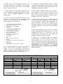
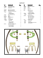
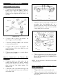
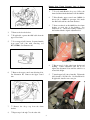
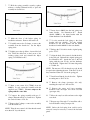
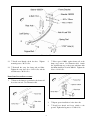
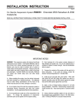
INSTALLATION INSTRUCTION
88092
Rev C
FOR RANCHO SUSPENSION SYSTEM RS6592:
FRONTIER
NISSAN XTERRA & 2WD
READ ALL INSTRUCTIONS THOROUGHLY FROM START TO FINISH BEFORE BEGINNING INSTALLATION
IMPORTANT NOTES!
WARNING: This suspension system will enhance the
off-road performance of your vehicle. It will handle
differently, both on and off-road, from a factory
equipped passenger car or truck. Failure to drive this
vehicle safely may result in serious injury or death to the
driver and passengers. ALWAYS WEAR your seat
belts, REDUCE your speed, and AVOID sharp turns
and other abrupt maneuvers.
A. New upper ball joints are required and must be
purchased separately to complete this installation. The
following ball joint part numbers will fit the Rancho
Upper Control Arm: Moog K9022, Elgin 1K9022,
McQuay-Norris FA1227, TRW (Federal Mogul) 10424,
& Nissan 4011001G25.
B. Before installing this system, have the vehicle’s
alignment and frame checked by a certified technician.
The alignment must be within factory specifications and
the frame of the vehicle must be sound (no cracks,
damage or corrosion).
C. Do not install a body lift kit with this suspension
system or interchange Rancho components with parts
from another manufacturer. Use the appropriate Rancho
shock absorbers. Contact your local representative for
the correct applications.
D. Do not chrome, cadmium, or zinc plate any of the
components in this system. To change the appearance
of components, enamel paint can be applied over the
original coating.
E. Each hardware kit in this system contains fasteners
of high strength and specific size. Do not mix hardware
kits or substitute a fastener of lesser strength. See bolt
identification table on page 2.
F. Compare the contents of this system with the parts
list in these instructions. If any parts are missing,
contact the Rancho Technical Department at 1-800-5746257.
G. Install all nuts and bolts with a flat washer. When
both SAE (small OD) and USS (large OD) washers are
used in a fastener assembly, place the USS washer
against the slotted hole and the SAE washer against the
round hole.
H. Apply a drop of thread locking compound to all
bolts during installation. CAUTION: Thread locking
compound may irritate sensitive skin. Read warning
label on container before use.
L. Suspension components that use rubber or urethane
bushings should be tightened with the vehicle at normal
ride height. This will prevent premature failure of the
bushing and maintain ride comfort.
I. Unless otherwise specified, tighten all nuts and bolts
to the standard torque specifications shown in the table
below. USE A TORQUE WRENCH for accurate
measurements.
M. The required installation time for this system is
approximately 4 to 5 hours. Check off the box ( ) at
the beginning of each step when you finish it. Then
when you stop during the installation, it will be easier to
find where you need to continue from.
J. Some of the service procedures require the use of
special tools designed for specific procedures. The
following tools and supplies are recommended for
proper installation of this system: N. This suspension system was developed using the
following tire & wheel combination: 265/75 R16 tire,
16 x 8 wheel with 5.5 inches of wheel backspacing. To
provide clearance, removing the mudguards and
trimming the wheel wells is necessary. Before installing
any other combination, consult your local tire and wheel
specialist.
Nissan Xterra/Frontier Service Manual
Upper Ball Joint 4011001G25 (see note “A”)
Ball Joint Remover HT72520000
Drill motor
Assorted Drills: 1/8" through 17/32"
Torque Wrench (250 FT-LB capacity)
1/2” Drive Ratchet and Sockets
Assorted Combination Wrenches
Heavy Duty Jack Stands
Wheel Chocks (wooden blocks)
Hydraulic Floor Jack
Center punch
File
Large "C" Clamps or Bench Vise
Hammer
Wire Brush (to clean bracket mounting surfaces)
Grease
Tape Measure
Safety Glasses (wear safety glasses at all times)
O. Important information for the end user is contained
in the consumer/installer information pack. If you are
installing this system for someone else, place the
information pack on the driver’s seat. Please include the
installation instructions when you finish.
P. Thank you for purchasing the best suspension
system available. For the best installed system, follow
these instructions. If you do not have the tools or are
unsure of your abilities, have this system installed by a
certified technician. RANCHO SUSPENSION IS NOT
RESPONSIBLE FOR DAMAGE OR FAILURE
RESULTING FROM AN IMPROPER OR MODIFIED
INSTALLATION…
K. It is extremely important to replace torsion bars, CV
flanges, and front drive shaft/pinion relationships as
original. Be sure to mark left/right, front/rear, and
indexing of mating parts before disassembly. A paint
marker or light colored nail polish is handy for this.
STANDARD BOLT TORQUE & IDENTIFICATION
Bolt Size
5/16
3/8
7/16
1/2
9/16
5/8
3/4
INCH SYSTEM
Grade 5
15 FT-LB
30 FT-LB
45 FT-LB
65 FT-LB
95 FT-LB
135 FT-LB
185 FT-LB
Grade 8
Bolt Size
20 FT-LB
35 FT-LB
60 FT-LB
90 FT-LB
130 FT-LB
175 FT-LB
280 FT-LB
M6
M8
M10
M12
M14
M16
M18
2
METRIC SYSTEM
Class 9.8
Class 10.9
5 FT-LB
18 FT-LB
32 FT-LB
55 FT-LB
85 FT-LB
130 FT-LB
170 FT-LB
9 FT-LB
23 FT-LB
45 FT-LB
75 FT-LB
120 FT-LB
165FT-LB
240FT-LB
Class 12.9
12 FT-LB
27 FT-LB
50 FT-LB
90 FT-LB
145 FT-LB
210 FT-LB
290 FT-LB
PARTS LIST
P/N
DESCRIPTION
180001
180002
334
CONTROL ARM, LEFT
CONTROL ARM, RIGHT
ADD-A-LEAF
1
1
2
860253
130014
860419
1412
BOXED SUB ASSEMBLY
Bump Stop Spacer, Rear
Front Droop Stop Hardware Kit
Droop Stop
5/16-24 Nyloc Nut
5/16 SAE Flat Washer
Bump Stop Spacer, Front
Sleeve
Bushing
Bushing Washer Kit
Washer
Front Hardware Kit
1/2” Loop Strap
Standoff Nut
1/4-20 x .75 HHCS
1/4-20 Nyloc Nut
1/4 SAE Flat Washer
Rear Bump Stop Hardware Kit
M10-1.25 x 50 HHCS
10mm Flat Washer
10mm Lock Washer
1
2
1
2
2
2
2
4
8
1
8
1
2
2
2
2
2
1
4
4
4
180004
420053
520053-4
860422
7852
860423
770095
770093
860424
QTY.
P/N
DESCRIPTION
860254
180003
420054
42702
7414
8011
BOXED SUB ASSEMBLY
Shackle
Sleeve
Thread Lock
U-bolt
U-bolt Hardware Kit
1/2-20 Nyloc Nut
1/2 SAE Flat Washer
Center Bolt Hardware Kit
3/8-24 x 4.5 Center Bolt
3/8-24 Hi-Nut
Shackle Hardware Kit
M12-1.75 x 130 HHCS
M12-1.75 x 110 HHCS
M12-1.75 Nyloc Nut
12mm Flat Washer
Information Pack
Rancho Decal
Instructions
Consumer/Warranty Information
Warning Sticker
860410
770091
770025
860426
94180
780281
88092
94119
94177
3
QTY.
1
2
2
2
4
1
8
8
1
2
2
1
2
2
4
8
1
1
1
1
1
FRONT SUSPENSION
UPPER CONTROL ARM ASSEMBLY
1.
Attach new ball joint (purchased separately) to
Rancho upper control arm 180001 as shown in
illustration #1. Refer to “Important Note A”.
Tighten the bolts (supplied with ball joint) to 1215 ft. lbs.
Illustration #2
3.
Measure and record the length of each torsion
bar anchor bolt. See illustration #3. As a
precaution, label the torsion bars left and right.
Paint matching marks on the torsion bar and the
corresponding lower control arm.
Illustration #1
2.
Apply a film of grease to the inside of the
tubes on upper control arm 180001.
3.
Insert two bushings (520053-4) into each tube
as shown in illustration #1.
4.
Apply a film of grease to the inside of the
installed bushings. Insert sleeve 420053 into each
bushing assembly.
5.
Repeat steps 1 through 4 to assemble Rancho
upper control arm 180002.
VEHICLE PREPARATION
UNLOADING
1.
2.
&
TORSION
Illustration #3
4.
BAR
Remove the tension on both of the torsion bars
by loosening the lock nuts and the adjusting nuts.
Ensure that the twisting force is eliminated from
the torsion bars.
NOTE: It is not necessary to remove the torsion bars
or the anchor bolts.
Park the vehicle on a level surface. Set the
parking brake and chock rear wheels. Measure
and record the distance from the center of each
wheel to the top of the fender opening. See
illustration #2.
SHOCK ABSORBER, UPPER CONTROL ARM, &
DROOP STOP REMOVAL
Raise the front of the vehicle and support the
frame with jackstands. Remove the front wheels
and set them aside.
4
1.
Support the lower control arm with a jack.
2.
Remove the nuts and bolts attaching the shock
to the frame bracket and lower control arm. See
illustration #4.
DROOP STOP, UPPER CONTROL ARM, & SHOCK
ABSORBER INSTALLATION
1.
Loosely attach Rancho droop stop 1412 to the
frame bracket with the hardware from kit 860419.
2.
Place Rancho upper control arm (180001 for
driver side or 180002 for passenger side) under
the ABS cable and into the frame brackets.
3.
Insert a washer from kit 860422 into the frame
bracket on each side of the bushing. See
illustration #7. Attach the bushing assembly to
the bracket with the original adjustment bolt.
Illustration #4
3.
Remove the shock absorber.
4.
If applicable, separate the ABS cable from the
upper control arm.
5.
Loosen upper ball joint nut. Separate knuckle
from upper ball joint with removing tool
HT72520000. See illustration #5.
Illustration #7
4.
Repeat step 3 for the other frame bracket and
bushing. Center adjustment cams but do not
tighten the adjustment bolts until the vehicle is at
normal ride height.
5.
Attach upper ball joint to knuckle. Tighten the
ball joint nut to 58-108 ft. lbs. See illustration #8.
If applicable, install a new cotter pin.
Illustration #5
6.
Remove the upper control arm adjusting bolts.
See illustration #6. Remove the upper control
arm.
Illustration #6
7.
8.
Remove the droop stop from the frame
bracket.
Illustration #8
Repeat steps 1 through 7 for the other side.
5
6.
Install new Rancho shock absorber. Do not
reuse original shock absorber.
7.
Align droop stop with control arm pad.
Tighten nut securely. See illustration #9.
Illustration #10
3.
Enlarge the mounting hole in the lower control
arm to 1/2”. See illustration #11. File the front
outside corner of the OE bump stop to provide
clearance for the sway bar.
Illustration #9
8.
If applicable, slide the protective sheaths on
the ABS cable to the locations shown in
illustration #9. Install the loop strap from
hardware kit 860423.
9.
Place a washer between the loop strap and
control arm. Attach the ABS cable to the front of
the control arm with the 1/4” hardware from kit
860423 (illustration #9). Tighten nut and bolt
securely.
10. Tighten the adjusting nut on the torsion bar
anchor bolt to the corresponding measurement
from illustration #3.
Illustration #11
NOTE: Adjustment of anchor bolt nut is in a
tightening direction only. Do not adjust by loosening
the nut. Final height adjustment is done with kit
installed and vehicle on the ground.
11. Repeat steps 1 through 10 for the other side.
4.
Place bump stop on spacer (180004) as shown
in illustration #11.
5.
Attach spacer and bump stop to lower control
arm with the standoff nut from hardware kit
860423. Tighten the nut to 12-16 ft. lbs.
6.
Repeat for other side.
7.
Apply grease to the upper control arm
bushings through the grease fittings.
BUMP STOP SPACER INSTALLATION
1.
Remove the nut attaching the bump stop to the
lower control arm. See illustration #10.
8.
Install front wheels and lower vehicle to the
ground. Tighten lug nuts to 87-108 ft. lbs.
2.
Remove the bump stop.
9.
Tighten the upper control arm adjustment bolts
to 72-87 ft. lbs.
6
REAR SUSPENSION
6.
Remove the leaf spring.
ADD-A-LEAF & SHACKLE INSTALLATION
1.
Chock front wheels. Raise the rear of the
vehicle and support the frame with jack stands.
Remove rear wheels and set them aside.
2.
Support the rear axle with a floor jack.
Disconnect the end links from the sway bar.
3.
Remove the upper and lower mounting
hardware from the left rear shock absorber (driver
side). See illustration #12.
4.
Remove the left rear shock.
5.
Remove the U-bolt nuts, spring pad, and Ubolts. Disconnect the leaf spring shackle and
remove the front eyebolt. See illustration # 13.
Illustration #12
Illustration #13
7
7.
Hold the spring assembly securely together
with two c-clamps (illustration #14) or place the
assembly in a bench vise.
Illustration #16
14. Insert sleeve 420054 into the leaf spring rear
frame bracket. See illustration #17. Attach
shackle 180003 to the frame bracket with the
12mm hardware from kit 860426.
Illustration #14
8.
9.
Mark the front of the helper spring for
installation reference. Remove the center bolt
15. Loosely attach the leaf spring to the front
bracket and rear shackle. Use the original
hardware for the front bracket and the 12mm
hardware from kit 860426 for the rear shackle.
Carefully remove the C-clamps or remove the
assembly from the bench vise. Set the helper
spring aside.
16. Enlarge the U-bolt holes in the original spring
pad to 17/32”.
10. Lightly grease the tip sliders of new add-a-leaf
334. Place the add-a-leaf on the bottom of the
existing spring pack and reinstall the helper
spring. See illustration #15.
17. Align the head of the center bolt with the hole
in the axle pad. Reinstall the original spring pad.
See illustration #17. Attach the axle to the leaf
spring with the new U-bolts, and the hardware
from kit 8011. Tighten the U-bolt nuts diagonally
to 72-80 ft. lbs.
NOTE: The amount of U-bolt threads exposed should
be equal after tightening the nuts. Trim the U-bolts if
they extend more than 1/2” below the spring pad.
18. Install new Rancho shock absorber. Tighten
mounting nuts to 30-37 ft. lbs.
Illustration #15
19. Remove the clamp (passenger side only)
attaching the sway bar to the rear axle.
11. Insert a new center bolt (770091) from kit
860410. Loosely secure the assembly with the
supplied nut (770025). Do not compress the
spring with the center bolt.
20. Remove the upper and lower mounting
hardware from the right rear shock absorber
(passenger side).
12. Compress the spring assembly with two Cclamps (illustration #16) or a bench vise. Tighten
the center bolt nut to 25 ft. lbs.
21. Move the sway bar aside and remove the right
rear shock.
22. Repeat steps 5 through 17 to install the add-aleaf and shackle on the passenger side.
13. Remove the C-clamps or remove the assembly
from the bench vise.
NOTE: Before the leaf spring front eyebolt can be
removed, it may be necessary to remove the fuel tank
guard.
NOTE: Trim the new center bolt if the threads extend
more than 1/2” beyond the nut.
8
Illustration #17
23. Install new Rancho shock absorber.
mounting nuts to 30-37 ft. lbs.
2.
Tighten
24. Reinstall the sway bar clamp and end links.
Tighten the sway bar bolts to 32-41 ft. lbs and the
end link nuts to 30-35 ft. lbs.
Place spacer 130014 against frame rail at the
bump stop location. See illustration #19. Attach
the original bump stop to the spacer and frame with
the 10mm hardware from kit 860424. Tighten the
bolts to 12-16 ft. lbs.
BUMP STOP SPACER INSTALLATION
1.
Remove the bump stop attached to the frame rail
above the rear axle. See illustration #18.
Illustration #19
Illustration #18
9
3.
Repeat spacer installation for the other side.
4.
Install rear wheels and lower vehicle to the
ground. Tighten the lug nuts to 87-108 ft. lbs.
5.
Tighten the leaf spring front pivot bolts to 86108 ft. lbs. and the rear shackle bolts to 58-72 ft.
lbs.
5.
With the suspension at maximum extension (full
droop), inspect and rotate all axles and drive shafts.
Check for binding and proper slip yoke insertion.
The slip yoke should be inserted a minimum of one
inch into the transfer case and/or transmission.
6.
Ensure that the vehicle brake system operates
correctly. If new brake hoses were installed, verify
that each hose allows for full suspension
movement.
7.
Readjust headlamps. Have vehicle Aligned at a
certified alignment facility.
FINAL CHECKS & ADJUSTMENTS
1.
Jounce suspension and move the vehicle to
normalize ride height. If you prefer optimum
clearance, adjust the tension on the torsion bars
until the left front and right front measurements are
both 22 inches. Refer back to illustration #2. If
you prefer optimum ride control, set the front
measurements to 21.5 inches.
Recommended Alignment Specifications
Caster (degrees): 2.17° to 3.07°
Camber (degrees): -.5° to .5°
Sum Toe In (inches): .12 to .20
NOTE: Adjust the nut on the anchor bolt in a tightening
direction only. Do not adjust the height by loosing the
nut.
2.
Tighten the lock nuts on the anchor bolts to 2230 ft. lbs.
3.
Remove mudguards and trim wheel wells if
Please retain this publication for future reference.
See Important Note O.
necessary. Refer to “Important Note N”.
4.
Turn the front wheels completely left then right.
Verify adequate tire, wheel, and brake hose
clearance. Inspect steering and suspension for
tightness and proper operation.
10