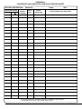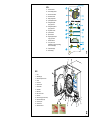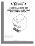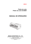
1
LS5
VACUUM & NON-VACUUM AUTOCLAVES
Instructions for use
110151
ST-IM61e
Read these Instructions before use
Preliminary
Information
Safety notes
and cautions
Keep these ‘Instructions for use’ in a safe convenient place for future reference. Read in
conjunction with the Publications detailed in Section 1.4 and 1.5.
Installation
Eschmann After Sales Service Department
Operation
Cleaning, care
and maintenance
Instructions for use
Technical data
The Eschmann After Sales Service Department is staffed and equipped to provide advice and
assistance during normal office hours. To avoid delays when making enquires, please quote the
Model and Serial Number of your Autoclave which is shown on the Serial Number plate, the
location of which is shown in Fig. 2 item 8. Please ensure you include all alpha and numeric digits
of the Serial Number.
For further information visit www.eschmann.co.uk
All correspondence relating to the after sales service of Eschmann Equipment to be addressed to :
UK Customers
Eschmann Equipment, Peter Road, Lancing, West Sussex BN15 8TJ, England.
Tel: +44 (0) 1903 765040. Fax: +44 (0) 1903 875711.
Overseas Customers
Contact your local distributor. In case of doubt contact Eschmann Equipment.
Patents and Trade marks
The ESCHMANN name and logo are registered trade marks of Eschmann Holdings Limited.
“Eschmann Equipment” is a trading name of Eschmann Holdings Limited.
“Little Sister” and “LS5” are trade marks of Eschmann Holdings Limited.
Patents Pending plus:
Pat. US5090033 and Pat. GB2238407.
Copyright © 2005 Eschmann Holdings Limited
All rights reserved. This booklet is protected by copyright. No part of it may be reproduced, stored in a
retrieval system or transmitted in any form or by any means, electronic, mechanical, photocopying,
recording or otherwise without written permission from Eschmann Holdings Limited.
The information in this publication was correct at the time of going to print. The Company, however,
reserves the right to modify or improve the equipment referred to.
The CE marking affixed to the product certifies that it complies with the
European Medical Devices Directive 93/42/EEC and related legislation.
ST-IM61e
May 2005
LS5
VACUUM & NON-VACUUM AUTOCLAVES
Contents
1
2
3
4
5
6
7
8
9
10
11
12
13
14
15
16
17
18
19
20
Introduction . . . . . . . . . . . . . . . . . . . . . . . . . . 4
Hazards . . . . . . . . . . . . . . . . . . . . . . . . . . . . 5
Limitations on use . . . . . . . . . . . . . . . . . . . . . 5
Electrical safety . . . . . . . . . . . . . . . . . . . . . . . 5
General safety . . . . . . . . . . . . . . . . . . . . . . . 5
Conditions for safe use . . . . . . . . . . . . . . . . . 5
Warning markings . . . . . . . . . . . . . . . . . . . . . 5
Safety features . . . . . . . . . . . . . . . . . . . . . . . 6
Declaration . . . . . . . . . . . . . . . . . . . . . . . . . . 6
Installation . . . . . . . . . . . . . . . . . . . . . . . . . . . 6
Control and panel details . . . . . . . . . . . . . . . 6
Mains switch . . . . . . . . . . . . . . . . . . . . . . 6
Push-button . . . . . . . . . . . . . . . . . . . . . . 6
Digital displays . . . . . . . . . . . . . . . . . . . . 6
Indicators . . . . . . . . . . . . . . . . . . . . . . . . 7
Initial preparation for use . . . . . . . . . . . . . . . 7
Loading the autoclave . . . . . . . . . . . . . . . . . . 7
Running a cycle . . . . . . . . . . . . . . . . . . . . . . 8
Special programmes/Functions/Tests . . . . . . 9
Cleaning and care . . . . . . . . . . . . . . . . . . . . 10
Maintenance . . . . . . . . . . . . . . . . . . . . . . . . 10
Printer instructions . . . . . . . . . . . . . . . . . . . 16
Installation . . . . . . . . . . . . . . . . . . . . . . 16
Output . . . . . . . . . . . . . . . . . . . . . . . . . 16
Paper roll renewal . . . . . . . . . . . . . . . . 16
Ribbon cartridge renewal . . . . . . . . . . . 17
Spares pack . . . . . . . . . . . . . . . . . . . . . 17
Technical data . . . . . . . . . . . . . . . . . . . . . . . 18
Accessories . . . . . . . . . . . . . . . . . . . . . . . . 18
Appendix 1 - Cycle B4 notes . . . . . . . . . . . . . . . 19
Appendix 2 - Safety checks . . . . . . . . . . . . . . . . 19
Appendix 3 - Daily record sheet . . . . . . . . . . . . 20
Table 1 Key to display A2 . . . . . . . . . . . . . . . . . 11
Table 2 Special functions . . . . . . . . . . . . . . . . . 12
Table 3 Error numbers and remedies . . . . . . . . 14
ST-IM61e
P3/20
1
Introduction
WARNING
Read these instructions before use and keep them in
a safe convenient place for future reference. The use
of this autoclave should be under the control of a
person with adequate sterilization training. The
operator remains responsible for ensuring that the
load is suitable for the process adopted. The autoclave
should only be used as specified by the manufacturer
and detailed within these instructions. Never tamper
with, bypass or interfere with any of the safety features.
There are no ‘operator’ serviceable parts inside the
autoclave. Eschmann Equipment is not responsible
for malfunction, or a reduced level of protection
provided by the equipment, if used in a manner not
specified by them. Only use in conjunction with
Eschmann accessories and mains lead.
RESERVOIR WATER QUALITY CAUTION
a. Eschmann recommend filling the reservoir with
‘Sterile Water for Irrigation’. This is low in
dissolved solids and has a low microbial count.
In the U.K. the Department of Health recommend
that ‘Sterile Water for Irrigation’ is used in benchtop Autoclaves (NHS Estates document
HTM2031).
b. If ‘Sterile Water for Irrigation’ is not being used
then Eschmann strongly recommend the use of
either distilled water, deionized water, purified
water or water treated by the reverse osmosis
process. These types of water are low in
dissolved solids and can help reduce the effects
of tap water detailed below.
1.1 For Customers on the Mainland of England,
Scotland and Wales, or on the Isle of Wight ONLY, when
you receive your Autoclave ensure that you complete your
Service Guarantee and Registration Card, and then
FREEPOST it to Eschmann Equipment. Failure to return
this card means you will not benefit from our FREE
installation service, which will ensure your Autoclave is
correctly installed, plus a FREE service visit during the
following 12 months.
1.2 This manual applies to the following Autoclaves fitted
with software version 1.51 (see section 19.7) or later:SES Little Sister 5 Autoclave
(from Serial Number L5NC....) REF 87-060-01
SES Little Sister 5 Vacuum Autoclave
(from Serial Number L5SA3C1001) REF 87-060-25
It is also applicable to earlier models of the LS5 autoclave
that has been upgraded by Eschmann or their accredited
agents and has software version 1.51 (see section 19.7)
or later.
1.3 These Autoclaves are designed for the sterilization
of instruments, utensils and other items. Only the Vacuum
models can sterilize wrapped or pouched items and hollow
instruments. They operate automatically and have
programmes at 134°C and at 121°C (with and without
drying). For sterilization times, refer to section 19.
1.4 The Service Manual (ST-SM33) containing a
technical description, complete maintenance procedures
and an illustrated list of spare parts is available on request
from the Eschmann After Sales Service Department.
1.5 A Manual (ST-IM55) providing the ‘Manufacturers
recommended instructions for testing vacuum autoclaves’
to the applicable parts of HTM2010 and DB9804 is available
on request from the Eschmann After Sales Service
Department.
c. DO NOT USE TAP WATER, this is high in
dissolved solids and can deposit lime scale,
block filters and cause damage to the pressure
vessel.
d. Eschmann also recommend changing the water
in the reservoir on a weekly basis, with the type
of water detailed in ‘a’ (or ‘b’) above. This will
reduce the build-up of contaminants in the water
that may cause blocked filters and/or damage
to the pressure vessel. Your local Health
Authority may suggest that you change the
reservoir water more frequently. Eschmann
advise you to follow your local Health Authority’s
recommendations.
P4/20
ST-IM61e
LS5
VACUUM & NON-VACUUM AUTOCLAVES
2
Hazards
2.1 The operator should be aware of the following
hazards:a.
b.
c.
d.
3
5
General safety
IMPORTANT
The design of the autoclave pressure vessel is
approved by a third party to International Standards.
In order to ensure safety and to comply with UK
and/or International regulations, the vessel and
fittings should be inspected by a ‘competent person’
at intervals of no more than 14 months. This can be
carried out by an Eschmann trained engineer. Also
see Appendix 2.
Burns to the operator caused by contact with hot
accessible surfaces of the load (use the ‘tray lifter’
to remove the sterilized load) and high temperature
internal surfaces of the chamber. Scalds to the
operator caused by hot water and/or steam from
the reservoir, from the chamber on opening the door
and from overfilling the reservoir.
The hazard of scalds and burns from contact with 5.1 The operator should follow these general safety
hot surfaces are greater during validation when the measures:covers may be removed which also exposes the
a. Do not cover the ventilation ports at the rear.
risk of electric shock. Validation should therefore only
b. Do not use abrasive powders, chemicals, or
be carried out by a qualified engineer.
solutions containing chlorine to clean the autoclave.
Infection, caused by contact with water in the
c. Do not attempt to open chamber door until unit has
reservoir if the reservoir is not drained and left to
cooled and internal pressure has fallen sufficiently to
dry as described in these instructions for use.
allow the door to be opened, by pressing the
The autoclave indicates a successful cycle, but the
button.
load remains non-sterile because the load is not
d. If an error display appears during a cycle, do not
suitable for the cycle selected. All loads and loading
switch-off power until discharge of hot water or
conditions should be validated. It is recommended that
steam into the reservoir has stopped.
the operator consults the instructions for use of the
items to be autoclaved and if in doubt consult a qualified 6
Conditions for safe use
microbiologist (or in the UK an Authorized Person).
6.1 This autoclave has been designed for use in the
Limitations on use
following conditions only:-
3.1 The operator should be aware of the following
limitations during use:
a.
b.
a.
b.
c.
d.
Indoor use.
Altitude from sea level up to 2000 metres.
Temperature 5°C to 40°C.
Maximum relative humidity 85% for the temperature
range above.
e. Mains supply voltage fluctuations not to exceed
±10% of the supply voltage.
Note: If it is required to operate this Autoclave outside of
these conditions, contact Eschmann Equipment at
the address given in these instructions.
Never use trays or cassettes without perforations.
Do not process porous loads (e.g. drapes and
gowns) or fluids in this autoclave.
c. Items in pouches should only be processed as
detailed in these instructions.
d. Do not use in zones of risk associated with
flammable anaesthetics.
e. When sterilizing instruments not of solid metal
construction, the manufacturer of the instrument 7
Warning markings
must be consulted about its suitability for
autoclaving. (Note: The sterilizing temperature may 7.1 The warning markings on this equipment have the
following meanings:
be exceeded during the drying phase).
Caution; refer to accompanying documents
4
Electrical safety
(i.e. these Instructions for Use).
4.1 The operator should follow these electrical safety
Caution; hot surface. This symbol warns the
measures:operator of high surface temperatures on the outside
a.
b.
c.
This equipment must be earthed.
Switch ‘off’ unit and disconnect from mains power
supply before renewing fuses, fitting the printer,
checking and cleaning the autoclave.
Do not attempt to service this equipment internally.
ST-IM61e
of the equipment.
WARNING: DO NOT USE TAP WATER
(see CAUTION in section 1)
P5/20
8
Safety features
8.1
The autoclave incorporates these safety features:-
a.
Cycle temperature button. Each time the
button
is pressed the cycle temperature will alternate between
134°C and 121°C. The temperature selected will be
indicated by the LED C adjacent to the temperature.
Door Interlock Switch and Door Catch Interlock
Switch. These prevent a programme starting if the
door and catch are not properly closed.
Pressure Relief Valve (safety valve). This valve
safely releases excess pressure up to a maximum
of 2.85+10%barG.
Microcomputer. The microcomputer constantly
monitors all key functions. If an error arises, it stops
the cycle, discharges pressure, and causes the
appropriate message to be displayed
Overheat Control. The microcomputer operates in
conjunction with an independent manual reset thermostat to protect the heating element from overheating.
Band Heater Thermostat (vacuum units only). This
prevents the band heater exceeding a preset
temperature.
b.
c.
d.
e.
9
Unwrapped load (with drying) cycle button. Press
the
button to select a cycle for an unwrapped load
with a drying phase after sterilization. The LED C
button will illuminate to show that
adjacent to the
this cycle has been selected.
Unwrapped load (without drying) cycle button.
Press the
button to select a cycle for an unwrapped
load without a drying phase after sterilization. The
LED C adjacent to the
button will illuminate to
show that this cycle has been selected. (Also see
Appendix 1)
Programme ‘P’ button. This button can be used in
combination with other buttons to activate special
programmes, functions and extended sterilization
cycle times. For more details see Section 15.
Declaration
9.1 The design of the autoclave pressure vessel is
approved by a third party to International Standards. This
equipment is defined as:Installation Category 2 (Overvoltage Category 2)
Pollution Degree 2 (in accordance with IEC664).
10
Cycle start button. (Always press and hold) Pressing
the
Open door button. (Always press and hold) When
the cycle has been completed (indicated on the process
Installation
display chart
open the door.
10.1 The Autoclave should be installed by a competent
person. UK Customers should arrange for this equipment
to be installed by an Eschmann Trained Engineer before
use. (For free installation and service, see section 1.1). All
programmes and functions can be deactivated or reactivated
by an Eschmann Trained Engineer, on request. The ability
to achieve this is protected from tampering, access can only
be gained by use of a ‘password’. Note that a levelling kit
(part number 112713) is available for the feet.
11
Control and display details
) press the
button to
Single wrapped load (with drying) cycle button.
(Vacuum autoclaves only) Press the
button to
select a cycle for a single wrapped load with a drying
phase after sterilization. The LED C adjacent to the
button will illuminate to show that this cycle has
been selected. See section 15.5 for daily testing
information.
11.4 Digital displays (see Fig. 1)
11.1 Open out the illustration page at the very back of this D1
manual to familiarise yourself with the controls and displays
shown in Fig. 1 and Fig. 2.
11.2 Mains switch
The mains switch is positioned at the front of the autoclave
(bottom left). The symbol ‘I‘ indicates ‘on’ and the symbol
‘0’ indicates ‘off’ (see 10, Fig. 2).
11.3 Push buttons (see Fig. 1)
Display change button. Button is disabled during
sterilization and drying phases. At any other time press D2
the
button to display the cycle counter in display
D1. If the autoclave is running a cycle the display will
show the cycle number in progress, or, if a cycle is not
running the counter will show the number of cycles D3
completed (including any aborted). The display will
revert to show the time of day five seconds after the
button is released.
P6/20
button will start the selected cycle.
Time, cycle counter, sterilization or drying time
(remaining), or error number display. This display
normally shows the time of day (to adjust the time
display see section 15.4, Special Functions, F8).
Whilst pressing button
this display will show the
cycle counter (see
in section 11.3). During the
sterilization or drying phase of a cycle (if applicable)
the display will show the number of minutes remaining
for that phase of the cycle. In the event of an error
occurring it will display an error code. For more details
on the error codes see Table 3.
Temperature display. This display normally shows
the actual chamber temperature. During special
functions it may display other details see details in the
‘Special functions table’.
Pressure display. This display normally shows the
measured chamber pressure. During special functions
it may display other details see details in the ‘Special
functions table’.
ST-IM61e
LS5
VACUUM & NON-VACUUM AUTOCLAVES
11.5 Indicators (see Fig. 1)
A1 Low water indicator. When this indicator is
illuminated the water reservoir is low and should be
refilled before the next cycle is started (see section
12.5).
A2 Process display indicator. This indictor
has 19 LEDs that illuminate to show the stage reached
during a sterilization cycle. Each LED indicates a
stage and this is detailed in Table 1.
C
12
12.5 With the door open fill the reservoir via the filling
cup (item 2, Fig. 2) up to the ‘MAX’ mark* engraved inside
the filling cup. Eschmann recommend the use of ‘Sterile
Water for Irrigation’ alternatively distilled or deionized water,
or water treated by reverse osmosis process can be used.
DO NOT USE TAP WATER. Close the door onto the
secondary catch only.
* Note: Only two litres of water are required to operate the
autoclave, the reservoir does not require filling to the ‘MAX’
mark if only a few cycles are to be run before the reservoir
is drained (see 16.2).
12.6 The autoclave has been designed to accept
A3 Door unlocked indicator. This indicator is
standard 100mm domestic extraction ducting at the rear
illuminated when the door is unlocked.
of the unit. Before connecting the unit to an extraction
system (to remove exhaust steam) check which type of
A4 Door locked indicator. This indicator is illuminated reservoir is fitted. If it has 4 plugs (‘A’ in Fig.3) remove
when the door is locked.
them and reposition them in the holes marked ‘B’ in Fig. 3.
Selection indicators. These indicators illuminate to If the plugs are not provided block of the holes marked ‘B’
show which function has been selected (cycle or in Fig. 3 with suitable adhesive tape and carefully make
four holes (6mm diameter) as shown ‘A’ in Fig. 3. Do not
temperature).
allow any swarf to enter the reservoir or make the holes
Initial preparation for use
lower than indicated.
12.1 When lifting or moving the Autoclave (with at least
two people), place the hands under the base at each side
of the unit. Place the autoclave on a flat, level, water and
heat resistant surface and ensure there is a working
clearance of 150 mm on the left hand side. Do not cover
the ventilation ports at the rear of the autoclave. The
autoclave does not require wall clearance at the back and
can be positioned flush against a wall (unless an extraction
unit is fitted see 12.6). Also see section 10.1.
WARNING
This equipment must be earthed. Ensure that the
mains plug is easily accessible during use as this
is the means of disconnection.
12.2 The unit is supplied with an IEC mains input socket
at the rear (see C, Fig. 3) and a selection of mains input
leads. If the lead has a fused plug the correct fuse will be
installed. If an alternative plug is fitted ensure that the plug
is earthed and check that the fuse (if it is a fused plug) is
appropriate for the voltage of the equipment (see rating
plate on base of cabinet item 8, Fig. 2). Connect the
required ‘Eschmann’ lead to the rear socket, DO NOT use
equivalents.
12.3 Connect unit to mains power supply and switch on
by selecting unit power switch ‘0-I’ to ‘I’ (10, Fig. 2). Various
displays will illuminate to show the autoclave has been
connected correctly, and is ‘on’.
3
13
Loading the autoclave
CAUTION
When loading the autoclave take care that you do
not damage the door or front face of the chamber,
especially the door seal and mating face. Damage
to these parts can adversely affect performance.
When loading pouches ensure they do not make
‘paper cuts’ in the door seal.
13.1 Check you have read the limitations on use
(section 3) and the technical specification.
13.2 Operators should note that as load types and load
arrangements vary greatly, validation of particular load
arrangements is essential (e.g. wrapped cassettes and
maximum loads). Steam penetration can also be affected
by extremes of humidity. If in doubt, seek advice from a
qualified microbiologist or Authorised Person.
12.4 To open the chamber door (16, Fig. 2) press button
B7 (Fig. 1) and then push the secondary catch (item 15,
Fig. 2) to the left (when viewed from the front) to release
the door. Remove the tissue paper from the door and
accessories from within the chamber. Remove all packing 13.3 The autoclave is designed to sterilize instruments,
pieces carefully and dispose of these and the carton in not to wash or clean them, therefore before loading
accordance with applicable recycling practices.
instruments into trays cassettes or pouches they should
be pre-washed. Preferably instruments should be washed
ST-IM61e
P7/20
in an ultrasonic cleaner or washer/disinfecter to remove
amalgam, debris, etc., then rinsed to remove all traces of
proprietary cleaners, chemicals or disinfectants. Residue
from these products could result in a blockage of the water
recycling system. If instruments are not cleaned this may
compromise the efficiency of the sterilization process.
13.4 When loading the autoclave note the guidelines that
follow for each type of autoclave:-
Vacuum autoclaves (unless these cycles have been
disabled see section 10.1). If this is the required cycle pass
on to section 14.6.
button. Each
To select a different temperature press the
is pressed the cycle temperature will alternate
time
between 134°C and 121°C. The temperature selected will
be indicated by the LED C adjacent to the temperature.
To select the required programme press the appropriate
button on the control panel ( ,
or
). The indicator C
for the selected programme will remain illuminated to show
which cycle has been selected. 134°C cycles can be
extended see section 15.
NOTE: Cycle temperature and programme can be selected
in either order and changed independently of each other
until the required ones have been selected. In the case of
low water a ‘beep’ will sound and the ‘low water indicator’
( Fig. 1) will flash.
Vacuum and Non-Vacuum Units - Unwrapped solid
items, buttons
and
Load unwrapped solid items loose on trays or into
cassettes. Do not overload trays or cassettes (see
TECHNICAL DATA for maximum tray loads). Avoid
‘bunching’ items together and ensure all items are
positioned so that they drain freely. Only use Eschmann
trays or cassettes and ensure that the load does not
block the holes in them. Loaded trays and cassettes
. The autoclave can
should then be placed in the sterilizing chamber. All items 14.6. Press the cycle start button
must be positioned so that they drain freely and do not be configured to have adjustable sterilization and drying
trap rising air bubbles. (Also see Appendix 1)
times (see section 10.1). The appearance of ‘ ’ in display
D2 indicates that the autoclave has been configured so
Vacuum Units ONLY - Validated hollow instruments
that these times can be adjusted. If these have been
including narrow lumens (e.g. dental handpieces),
enabled for a cycle (‘ ’ in display D2) follow section 14.6.2
single wrapped hollow or solid instruments
‘i-iii’ before continuing with section 14.7; if they are not
(see 2.1 d) button
.
enabled (‘ ’ does not appear in display D2) for that cycle
Sterilization of instruments, or other items in pouches
follow section 14.6.1 before continuing with section 14.7.
should only be done using the special pouch rack. Avoid
14.6.1
The sterilizing cycle will now proceed
packing pouches too tightly and note that paper/film
automatically and the printer (if fitted) will commence
pouches must be loaded such that the film sides of
printing. Vacuum cycles may pause to cool the
adjacent pouches are face to face and sterilized using
chamber if it is above a preprogrammed limit. As the
this cycle with drying. Only use pouches recommended
for steam sterilization, see Accessories section 20. Items
will show the
cycle progresses indicator
should not be multiwrapped unless the load configuration
cycle stage reached (see Table 1) and the digital
has been validated by a suitably qualified person (possibly
displays D2 and D3 will display the actual chamber
using an extended drying time). Also see section 15.5.
temperature and pressure respectively. During the
sterilization or drying phase of a cycle (if applicable)
14 Running a cycle
the display D1 will show the number of minutes
remaining for that phase of the cycle. If a printer is
14.1 Select mains ‘on/off’ switch to ‘I’ (on) (item 10, Fig. 2)
fitted see section 17.5. Now pass on to section 14.7.
and open the door by releasing the secondary catch (item
15, Fig. 2). NOTE: If the door was locked closed when
14.6.2 (i) As ‘ ’ has appeared in display D2 this cycle
switching ‘on’ indicator
will flash and the
button
allows the sterilization time to be increased. D2 will
should be pressed to unlock the door, the secondary catch
show ‘ ’ and display D1 will flash and show the
can then be released.
current sterilization time in minutes and seconds.
To increase this time press and hold the
button,
14.2 Load the autoclave with the items to be sterilized as
to
reduce
this
time
press
and
hold
the
button,
detailed in section 13.
until the sterilization time is the desired value. Press
14.3 Check that the low water level indicator ( , Fig. 1)
button
to accept this time. Pressing the
is not illuminated, if it is fill reservoir (see section 12.5).
button at any point before the cycle starts causes
the autoclave to move back one stage in this
14.4 Close the door and hold it firmly shut until the
process.
automatic door lock operates. This is shown by indicator
switching off and indicator switching on. NOTE: A
cycle cannot be selected with the door open. When running
repeated cycles the display will retain the last cycle selected
(shown by the illumination of indicators C).
14.5 The autoclave will automatically select a 134°C
unwrapped cycle
with drying for Non-vacuum
autoclaves or a 134°C wrapped cycle
with drying for
P8/20
14.6.2 (ii) If the cycle has a drying phase, ‘
’ will
appear in display D2 to indicate that this cycle allows
the drying time to be increased. If ‘
’ does not
appear in display D2 pass on to section 14.6 2 (iii).
Display D2 is showing ‘
’ and display D1 will flash
and show the current drying time in minutes. To
increase this time press and hold the
button, to
ST-IM61e
LS5
VACUUM & NON-VACUUM AUTOCLAVES
reduce this time press and hold the
button, until
the drying time is the desired value. Press button
to accept this time. Pressing button
at any
point before the cycle starts causes the autoclave
to move back one stage in this process.
14.6.2 (iii) The sterilizing cycle will now proceed
automatically and the printer (if fitted) will commence
printing (vacuum cycles may pause to cool the
chamber if it is above a preprogrammed limit). As
the cycle progresses indicator
will show
the cycle stage reached (see Table 1) and the digital
displays D2 and D3 will display the actual chamber
temperature and pressure respectively. During the
sterilization or drying phase of a cycle (if applicable)
the display D1 will show the number of minutes
remaining for that phase of the cycle. If a printer is
fitted see section 17.5.
15.3 Accelerated condense.
The condensing time can be reduced by approximately 3
minutes (but more steam may be liberated by the
is pressed when ‘Phase 4 autoclave) if the ‘P’ button
LED1’ is illuminated (see Table 1). NOTE: Autoclave
‘beeps’ when ‘Phase 4 - LED1’ illuminates.
15.4 Special functions.
Switch ‘off’ the mains switch (item 10, Fig.2). Press and
hold in the ‘P’ button
whilst switching the mains switch
back ‘on’ to make available several special functions as
detailed in the special functions table. When the autoclave
is switched on in this way display D1 only will be illuminated
(with other displays as required depending on which function
is selected). Initially display D1 will show F0, each time the
is pressed, this will increase from F0 up to F8
‘P’ button
(F4, F5, F6 vacuum autoclave only and with door closed),
is
and then back to F0 again, until either the start button
pressed
to
select
that
function,
or,
the
autoclave
is
switched
14.7. If a cycle “with drying” is selected then
is pressed (with the door open) to cancel special
commencement of the drying phase is indicated by ‘off’ or
function
selection.
(see Table 1). On non-vacuum units the door
opens automatically (onto secondary catch) prior to the 15.5 Daily Testing, Vacuum autoclaves
start of drying. On vacuum units the door cannot be opened
until the drying phase has been completed.
IMPORTANT:
14.8 On completion of a sterilizing cycle ‘without drying’,
indicated by
(see Table 1) and an audible signal,
the door can be released by pressing
. (Also see
Appendix 1).
14.9 Open the door fully and remove the load USING
THE TRAY LIFTER and leave the door open on the
secondary catch when not in use.
14.10 If during a cycle an error is detected display D1 will
display an error number (see section 17.3).
15
Special programmes/functions/tests
The Eschmann LS5 Vacuum Type-S and QuickVac
Steam Penetration Test Device (hereafter called
‘Device’) has been developed and validated solely
for use in the Eschmann LS5/SES2555 Vacuum
Type-S and Eschmann QuickVac Steam Sterilizers.
Use of the ‘Device’ in any other sterilizer, or use with
any other type of indicator, may give dangerously
misleading results. The ‘Device’ must only be used
and stored as detailed in the ‘Instructions for Use’
supplied with the ‘Device’. Failure to replace the
‘Device’ after 100 uses could lead to failure of the
‘Device’ and dangerously misleading results.
15.1 Extended sterilization time.
15.5.1
In order to sterilize products and devices by
steam, steam must be able to penetrate through to and
contact all surfaces. Items such as packaging, pouches,
narrow or hollow instruments are not easy to penetrate
with steam. For this reason, the LS5/SES2555 vacuum
autoclave has been fitted with a pump to remove air and
thus allow steam to penetrate into the load. The Eschmann
LS5 Vacuum Type-S and QuickVac Steam Penetration Test
Device (order REF 87-040-71) has been designed to test
the steam penetration ability of the autoclave, by presenting
a defined challenge to the autoclave. The device consists
of a plastic tubular device with an indicator receptacle at
the end and is supplied with indicator strips. The device
15.2 Extended drying time.
The drying time can be extended in 5 minute steps to a must be replaced after 100 uses. This device satisfies the
maximum of 50 additional minutes by pressing the ‘P’ requirement to perform a daily steam penetration test as
button
when ‘Phase 5 - LED1’ is illuminated (see Table given in:
1). Each time the ‘P’ button is pressed the drying time will EN 554:1994 Sterilization of medical devices - Validation
be increased (by 5 minutes, or back to 0 after 50) and the
and routine control of sterilization by moist heat, British
time added to the normal drying time will be displayed in
Standards Institution, clause 6.3.4
display D1. After a few seconds display D1 will revert to DB 2002(06) Device Bulletin, Benchtop Steam Sterilizersthe total remaining drying time. NOTE: Autoclave ‘beeps’
Guidance on purchase, Operation and Maintenance,
when ‘Phase 5 - LED1’ illuminates.
Medical Devices Agency, clause 5.3.1
Pressing the ‘P’ button
(indicator C adjacent to
will
illuminate) before pressing the start button
extends
the sterilization time from 3 minutes 5 seconds to 18
minutes. This extended cycle only works on the 134°C
cycles (not 121°C cycles). Pressing the ‘P’ button
again
before starting the cycle will cancel the function (indicator
C will go out). Alternatively press the ‘P’ button
(during
any cycle) when Phase 3 LEDs 2-7 are illuminated (see
Table 1) to increase the sterilization time by one sixth of
the selected sterilization time (one Phase 3 LED will go off
for each press, to indicate this).
ST-IM61e
P9/20
SN 2002(24) Safety Notice, Steam penetration tests in
vacuum benchtop sterilizers, Medical Devices Agency.
DB 2000(05) Device Bulletin, Guidance on the Purchase,
Operation and Maintenance of Vacuum Benchtop Steam
Sterilizers, Medical Devices Agency, clause 5.3.1
DB 9804 Device Bulletin, The validation and periodic
testing of benchtop vacuum steam sterilizers, Medical
Devices Agency, clause 5.1
Note: Some of the above documents are available on
the Medical Devices Agency’s website, www.medicaldevices.gov.uk
15.5.2 Frequency of use
To comply with the requirements of the regulatory
documents listed above, the steam penetration test must
be conducted at the commencement of each day that the
autoclave is to be used. This ‘verifies’ the suitability of
the autoclave’s air removal stage for the day ahead.
‘Appendix 3’ provides an example of a ‘Test Log’ that can
be photocopied and used to record the results. Eschmann
recommend the daily use of the device and the ‘Test Log’.
15.5.3 Conducting the test
12.5). Regular cleaning of the reservoir will reduce the
effects of excessive contaminants (e.g. handpiece
lubricant) which could be detrimental to the function of the
autoclave. For guidance on clean steam management and
HTM2031 contact Eschmann.
16.3 Attention to the following will increase the life of the
your Autoclave:a. Always leave the chamber door open on its
secondary catch when not in use.
b. At weekly intervals, lightly clean door seal and
chamber face with a lint-free cloth.
c. At weekly intervals remove any dirt or debris
that has collected around the gauze filter (item 7,
Fig. 2).
d. At monthly intervals remove any dirt or debris around
the gauze filter (item 7, Fig. 2) then gently pull it out
of its recess. Clean the recess and the filter carefully.
Replace the filter before using the autoclave again.
e. Replace the antibacterial filter on vacuum units (item 1,
Fig. 2) every three months. To remove the filter pull
gently whilst twisting. Replace by pushing a new one
into the rubber mount (small spigot facing out).
Cycle
(includes a drying phase) should be used to run
this test, or special function F6 (reduced cycle time as no 17 Maintenance
drying), if the autoclave is cool and dry before loading it
with the ‘Device’. Remember the ‘Device’ must be removed (ENSURE YOU HAVE
within 10 minutes of the cycle end.
17.1 Fuse Renewal
16
Cleaning and care
WARNING
Chlorine, even in the concentrations found in tap
water, can cause stainless steel to crack and could
damage the chamber. Disconnect from the mains
electrical supply before cleaning the Autoclave. Also
see Appendix 2.
16.1 Keep chamber trays, door seal and chamber face
clean. These should only be cleaned with a lint-free cloth.
Clean the outside of the autoclave by wiping down with a
cloth dampened with a 70% solution of industrial methylated
spirit (IMS) and water. Allow to dry by evaporation.
NOTE: Do not use abrasive powders, chemicals, or
solutions containing chlorine to clean the autoclave.
CAUTION
In common with other systems containing static
water reservoirs, water used in this unit can become
contaminated over a period of time, or following an
aborted cycle, and should be treated as a potential
risk of infection.
16.2 The reservoir should be drained weekly and allowed
to dry. To drain the reservoir release the reservoir tap
(item 12, Fig. 2) with the drain tube (item 11, Fig. 2) from
its clips (item 13, Fig. 2) at the bottom of the door and
open the tap by releasing the clip (see inset photographs
of open and closed tap in Fig. 2). Replace the drain tube
into its clips and ensure that it does not become trapped
when closing the door. Refill the reservoir (see section
P10/20
READ SECTIONS 2-8)
Fuses are fitted at the front of the autoclave (item 9, Fig. 2).
For fuse ratings refer to ‘TECHNICAL DATA’. To extract a
fuse switch ‘off’ the unit and disconnect from the mains
power supply, insert a screwdriver or small coin in the slot
of the fuse holder and twist it counter-clockwise. After
inspecting or renewing a fuse, reverse the above procedure
to re-secure fuse holder.
17.2 Preventive Maintenance Agreement
We would strongly recommend that a ‘P.M.A.’ is taken out
on your Autoclave. Although the autoclave requires minimal
maintenance, it is important to have the autoclave checked
and calibrated at regular intervals. This ensures that the
exacting conditions necessary for sterilization are
maintained throughout the unit’s working life.
17.3 Errors and faults
a
b
c
If, after switching ‘on’ power there is no visual display,
first check power supply connections, both fuses at
the front of the unit (see Fuse Renewal) and the
fuse in the mains plug (if it is a fused plug).
If an error occurs during a cycle (i.e. any time after
pressing the start button
), the cycle will abort
and provided power supply to the unit is maintained,
the error number will be indicated by the visual
display D1 (displays D2 and D3 will be continue to
show actual temperature and pressure).
If power fails during a cycle, check supply
conditions and fuses at the front of the unit and in
the mains plug if fused, also check the mains lead
ST-IM61e
LS5
VACUUM & NON-VACUUM AUTOCLAVES
d
e
f
is correctly connected at both ends. Once power
is restored the display D1 will show the error
number (D2 and D3 will be blank) until cleared by
switching the autoclave ‘off’ and then ‘on’ whilst
depressing the start button
. Release button
when the display appears.
Most errors will require investigation by an
Eschmann trained engineer who will need to know
the model serial number (see the serial number plate
item 8, Fig. 2) and error number. To display the last
error number in display D1 press buttons
and
together at any time.
Errors that can be corrected by the operator are
detailed in the error table, see Table 3.
Should the heating element reset thermostat
operate (in a nil water condition) this can be reset
by pressing the ‘reset button’ on the underside of
the autoclave (approximately 11cm in on the left
hand side underneath the unit as indicated on the
side of the unit).
17.4 Service
The Eschmann After Sales Service Department is staffed
and equipped to provide advice and assistance during
normal office hours. To avoid delays when making enquires,
please quote the Model and Serial Number of your
Autoclave (NOTE: For location of the serial number plate
see item 8, Fig. 2). If reporting an error please quote the
displayed error number. All correspondence relating to the
after sales service of Eschmann Equipment should be
addressed to :
After Sales Service Department
Eschmann Equipment,
Peter Road, Lancing, West Sussex, BN15 8TJ
Tel: +44 (0) 1903 765040 Fax: +44 (0) 1903 875711
Also see Appendix 2.
17.5 Printer message
TABLE 1
KEY TO DISPLAY A2
Phase 1
LED 1
LED 2
LED 3
Cycle started.
Chamber minimum fill achieved.
Chamber filled with water.
Phase 2
LED 1
LED 2
LED 3
Heater on.
Approximately 90°C reached.
Final heating phase started.
Phase 3
LED 1
LED 2-7
Sterilization phase started.
One sixth of the sterilization time
completed for each LED illuminated.
Phase 4
LED 1
LED 2
LED 3
Condensing stage started
Water removed from chamber.
Pressure approaching ambient.
Phase 5
LED 1
LED 2
LED 3
Start of drying phase.
Drying phase 50% completed.
Cycle completed (audible beep).
If a printer is fitted to your autoclave note that at specified
intervals it will print a message to remind you that ‘Service
and Certification’ is due. When this message appears
Eschmann recommend that you contact them to arrange
this as soon as possible (see contact details in section
17.4 above).
ST-IM61e
P11/20
TABLE 2 - SPECIAL FUNCTIONS
(See section 15.4 which provides instructions for accessing these special functions)
DISPLAY FUNCTION
METHOD OF USE
F0
Protected functions
To use this function requires the knowledge of the PIN code. This is normally
restricted to a trained service engineer who has access to this code and the
autoclave ‘Service Manual’. Therefore access to protected functions is not
available to the operator.
F1
Printer test
(Note: The printer should be loaded with paper before entering this special
to start
functions mode). With display D1 showing F1 press the start button
the printer test, a character set printout, display D1 shows F11. To stop the test
, the printer will stop at the end of the test cycle, display D1
press button
shows F0. To resume normal use switch ‘off’ the mains switch (item 10, Fig. 2)
and then switch back ‘on’, or press
with the door open.
F2
Cycle history
With display D1 showing F2 press the start button
to start printing a summary
of the last five cycles completed by the unit (cycle temperature, cycle type, cycle
count, date and time at start of cycle, date and time at end of cycle and the cycle
result). Display D1 returns to F0. To resume normal use switch ‘off’ the mains
switch (item 10, Fig. 2) and then switch back ‘on’, or press
with the door open.
F3
Set delayed start
With display D1 showing F3 press the start button
to enter the delayed start
time setting mode and delayed start initiation, display D1 will show
.
If the start hour displayed in D2 is correct (as set last time) and the minutes can
be assumed correct (as set last time) press the start button
to programme
the autoclave to start automatically at this set time. The display D1 will change to
F0 when
is pressed. Press
with the door open to exit the setting mode.
If the start time is not correct when entering function F3 (display D1 showing
, display D2 showing the hour set in 24 hour clock mode) press
to
to reduce it). Press
to confirm the hour when it is
increase the hour (or
correct. Display D1 will show
, to increase the minutes (shown in D2)
press
, or
to reduce them. Press
to confirm the minutes. The display
D1 will show F0. Press
with the door open to exit the setting mode.
The autoclave should be left switched ‘on’ with the required load in place, the
door shut and the required cycle selected as follows. When the door is shut a ‘ ’
flashes ‘on and off’ after the time in display D1. This continues while the program
selection and any adjustments to it are made (see sections14.6.2 if ‘ ’ appears
in display D2). When cycle selection has been completed and
is pressed to
confirm them, the ‘ ’ stops flashing. The cycle selected will be run automatically,
starting at the time set, a ‘ ’ will be displayed in D1 after the time to show that a
delayed start time has been set. (Also see Appendix 1)
On completion of the cycle the autoclave is ready for the load to be removed and
normal use resumed without the need to exit from the special functions mode.
Note: If the same delayed start time is required each day the setting can be
entered quickly once display D1 shows F3, by pressing (
).
F4
Leak Test
With display D1 showing F0 close the autoclave door (if open), press
until
display D1 shows F4, press
. Indicator will flash, press
to open the door,
indicator
will illuminate. Close the door, will illuminate, press
this starts
an automatic leak test which checks to see if the autoclave system is still pressure
tight. Display D3 will show the chamber pressure, after a few minutes display D2
will show the pressure rise to the nearest 0.1kPa.
(Vacuum Autoclave ONLY)
Note. To conduct this test the
chamber temperature must be
below 50°C to avoid an Error 38,
and the door closed before
selecting F4.
Table 2 is continued over page
P12/20
ST-IM61e
LS5
VACUUM & NON-VACUUM AUTOCLAVES
TABLE 2 (continued) - SPECIAL FUNCTIONS
DISPLAY FUNCTION
METHOD OF USE
F4
Leak Test (continued)
After a further 10 minutes if the pressure has not risen by more than 1.3kPa
display D2 will show
indicating the autoclave has passed the test (or
to indicate the autoclave has failed the test) and an audible sound will be heard.
and wait until display D2 and D3 go blank. To resume normal
Press button
use switch ‘off’ the mains switch (item 10, Fig. 2) and then switch back ‘on’, or
with the door open.
press
F5
Air detection test
For details on how to conduct this test consult manual ST-IM55 (issue ‘d’ or later).
(Vacuum Autoclave ONLY)
F6
Steam penetration test. With display D1 showing F0 close the autoclave door (if open), press
until
.
Indicator
will
flash,
press
to
open
the
door,
display
D1
shows
F6,
press
(Vacuum Autoclave ONLY)
Note. To conduct this test the indicator will illuminate. Place the Eschmann LS5 Vacuum Type-S and QuickVac
door must be closed before Steam Penetration Test Device in it’s pouch (see test device instructions for use)
,
and into the chamber. Close the door, will illuminate, press the start button
selecting F6. Also see 15.5.3.
this will start a special
cycle (no drying), D2 and D3 will show temperature
and pressure as normal during the cycle. At the end of the cycle the normal
audible sound will be heard. Press
to open the door, display D1 will be showing
F0. Remove the test pack and review the result within 10 minutes (see Test Device
instructions for use). To resume normal use switch ‘off’ the mains switch (item 10,
Fig. 2) and then switch back ‘on’, or press
with the door open. (NOTE: This
function can also be used to carry out HTM2010 Performance Qualification (PQ)
Tests in conjunction with the manuals detailed in sections 1.4 and 1.5).
F7
Disinfect function
Note. To conduct this test the
door must be closed before
selecting F7.
F8
Adjust date and time
ST-IM61e
(NOTE: The ex-factory condition is for this function to be disabled. It can be enabled,
if required, during installation by an Eschmann trained engineer.) With display D1
showing F0 close the autoclave door (if open), press
until display D1 shows
F7, press
. Indicator will flash, press
to open the door, indicator
will
illuminate. Load the autoclave with the load to be disinfected and close the door,
will illuminate. Press the start button
to start the disinfect function (a 2.5 minute
disinfect time at 110°C), D1 will continue to show F7 during the cycle and D2 and
D3 will show temperature and pressure. At the end of the cycle the normal audible
sound will be heard. Press
to open the door and remove the load. Display D1
will be showing F0. To resume normal use switch ‘off’ the mains switch (item 10,
Fig. 2) and then switch back ‘on’, or press
with the door open.
With display D1 showing F8 press the start button
to enter the adjust date
and time function. Display D1 will show
and D2 will show the year, to
increase the year press
(or
to reduce it) when correct press button
to
confirm the year. The display D1 will show
and D2 will show the month in
numerical format, to increase the month press
(or
to reduce it) when
correct press button
to confirm. The display D1 will show
and D2 will
(or
to reduce
show the day in numerical format, to increase the day press
it) when correct press button
to confirm. The display D1 will show
and
D2 will show the hour, to increase the hour press
(or
to reduce it) when
correct press button
to confirm. The display D1 will show
and D2 will
show the minute, to increase the minute press
(or
to reduce it) when
correct press button
, display D1 shows F0 display D2 and D3 will be blank.
was pressed).
The time and date are now set (seconds were set to zero when
Press
with the door open to continue normal use.
P13/20
TABLE 3 - ERROR NUMBER DETAILS AND REMEDIES
Clearing error display and restarting a cycle
WARNING
4
Open the door : Note will be flashing, open the
door by pressing
. If the door fails to open see NOTE
below, there may still be water in the autoclave.
If an error display appears during a cycle, do not
attempt to open the chamber door until the unit has
cooled (for safety below 50°C) and internal pressure
has fallen sufficiently to release the door, see below
‘3 Check pressure’. Where a cycle is aborted and/or
an error display is indicated the load should be treated
as non-sterile. The load should be re-wrapped if
wrapped and then sterilized by running the cycle again.
Also note the Caution after section 16.1 concerning
the contamination of water in the reservoir.
NOTE: Door opening problems. Although unlikely, there
may be up to a litre of water (which could be HOT) still in
the chamber. Be prepared to collect this water in a suitable
container. A built-in safety feature inhibits door opening
unless the following procedure is adopted. Switch OFF at
mains switch (item 10 Fig. 2). Press-and-hold-in the ‘Door
open button’ (
Fig.1) whilst switching back ON with the
mains switch (item 10 Fig. 2) wait two seconds and then
(which will open the door)
before releasing button
hold a container in place under the door to collect any
1
Record error number : For future reference record (HOT) water.
the error number before clearing the display. In the event 5
Check and prepare the aborted load : Loads must
of mains power failure, power must be restored to the be considered non-sterile if an error occurs and should be
autoclave to achieve this. (Also see 17.3d)
resterilized. All aborted wrapped loads should be dried,
2
Clear error and reset autoclave : To clear the error
display and reset the autoclave wait until any audible
discharge of water and steam has stopped and switch OFF
the autoclave with the mains switch (item 10 Fig. 2). Wait
10 seconds, press-and-hold-in the ‘Start button’ (
Fig.1)
whilst switching back ON with the mains switch (item 10
Fig. 2), immediately the normal display appears release
the ‘Start button’ (
Fig.1).
placed in new pouches and reprocessed.
6
Check chamber before starting another cycle :
The chamber should be allowed to dry and cool before
starting another cycle. To start another cycle select the
cycle and start the autoclave in the normal manner.
7
If the error persists or an error number occurs that
is listed at the end of this table then call the Eschmann
After Sales Service Department (see section 17.4) or
3
Check pressure : Before attempting to open the contact your approved service engineer. Do not attempt to
door note the pressure reading, this should be below solve an error using tools or tampering with the autoclave.
104kPa before the door is opened.
DISPLAY
is on
CAUSE
REMEDY
Water level too low.
Fill reservoir as detailed in section 12.5
flashing
Cycle started and water.
level is too low
Fill reservoir as detailed in section 12.5
Err01
Mains supply failure
during a cycle
a.
b.
c.
d.
Err03
Fill error
Follow ‘Clearing error display and restarting a cycle’ but before
starting a new cycle check the reservoir water fill level and dry the
water level sensors (item 17, Fig. 2). If door fails to open see
section 4 of ‘Clearing error display and restarting a cycle’.
Err04
Low water
a. Check the autoclave is not over loaded.
b. Check that the load cannot collect water (e.g. a kidney dish
not inverted) re-position load if required so that it can drain.
c. Dry the water level sensors (item 17, Fig. 2).
d. Follow ‘Clearing error display and restarting a cycle’.
A programmed test has
detected a possible fault
and aborted the cycle.
Follow ‘Clearing error display and restarting a cycle’ but before
starting a new cycle check door seal and chamber sealing face
are clean and not damaged. Damaged seals need replacing.
Err10, 13, 14,
23, 24 and 25
Check local supply conditions and all fuses.
Check supply plug wiring and power cable for possible breaks.
Check if Autoclave has been switched OFF accidentally.
Follow ‘Clearing error display and restarting a cycle’.
(continued over page)
P14/20
ST-IM61e
LS5
VACUUM & NON-VACUUM AUTOCLAVES
TABLE 3 - ERROR NUMBER DETAILS AND REMEDIES (continued from page 14)
DISPLAY
Err26
CAUSE
REMEDY
Water sensing error
early in cycle
a. Check load is not touching water sensors (item 17, Fig. 2) and
re-position load if required.
b. Dry the water level sensors (item 17, Fig. 2).
c. If door fails to open see section 4 of ‘Clearing error display
and restarting a cycle’.
d. Follow ‘Clearing error display and restarting a cycle’.
Heating error
Follow ‘Clearing error display and restarting a cycle’ but check
the reset button before starting a new cycle, see section 17.3 ‘f’.
Err 33
Water sensing error
later in cycle
a. Gauze filter blocked, see section 16.3 ‘c’ and ‘d’.
b. Check load is not touching water sensors (item 17, Fig. 2) and
re-position load if required.
c. Dry the water level sensors (item 17, Fig. 2).
d. If door fails to open see section 4 of ‘Clearing error display
and restarting a cycle’.
e. Follow ‘Clearing error display and restarting a cycle’.
Err35
Door failed to open
Follow ‘Clearing error display and restarting a cycle’ but note
during drying phase that it may be required to assist opening the
door manually.
Err36
Door unlocked during cycle
a. Follow ‘Clearing error display and restarting a cycle’.
b. Check that when door is closed, green LED (item A4 Fig. 1) is
illuminated. If red LED (item A3 Fig. 1) is illuminated contact
Eschmann Equipment (see section 17.4).
Chamber temperature
or pressure error
Follow ‘Clearing error display and restarting a cycle’ but
allow the autoclave to cool down before starting another cycle.
Water level sensor error
a. Check load is not touching water sensors (item 17, Fig. 2) and
re-position load if required.
b. Dry the water level sensors (item 17, Fig. 2).
c. If door fails to open see section 4 of ‘Clearing error display
and restarting a cycle’.
d. Follow ‘Clearing error display and restarting a cycle’.
Door not opening
after several attempts
a. Try gentle assistance to open the door.
b. Temperature etc. may be too high, wait 5-10 minutes then
follow ‘Clearing error display and restarting a cycle’.
c. If door still fails to open see section 4 of ‘Clearing error
display and restarting a cycle’.
Miscellaneous
Follow ‘Clearing error display and restarting a cycle’ and if
problem repeats contact Eschmann Equipment (see section 17.4).
Err27, 28
29 and 30
Err38, 39, 40
Err 44, 45
Err46
Any other
error code
ST-IM61e
P15/20
18
Operating instructions for printer
IMPORTANT OPERATOR NOTES
Follow the notes and cautions below when changing
the paper roll and ink ribbon cartridge. Also do not
pull on the paper whilst the printer is in operation,
it may damage the print head. Using knives, etc. to
remove a paper jam will also damage the print head.
Always open the front panel and use the paper feed
button (item 15 Fig. 4.3) to clear the jam.
18.1 Printer installation (REF 87-066-66)
If an error occurs during the cycle, it is recorded with date
and time on the printout and the message ‘CYCLE FAILED’.
Errors are designated by error codes as Table 3.
Cycle stage codes on the printout are:
TPV*
End of vacuum pulses
TPP*
End of first pressure pulse
TSS
Start of sterilization
TSE
End of sterilization
TDS
Start of drying phase
TDE
End of drying phase
(* Vacuum Autoclaves ONLY)
18.3 Paper Roll Renewal
Install the printer unit in the autoclave as follows:
a
b
c
d
e
f
Remove the printer from its packaging and remove
the mains power supply from the autoclave.
To gain access to the printer compartment open the
printer door (13, Fig. 4.2 and 4.4) by turning the door
latch (17, Fig. 4.4) anticlockwise with a small coin
or suitable screwdriver.
Remove the printer connector (2, Fig. 4.1) from its
storage pocket (3, Fig. 4.1) and gently pull out the
ribbon cable (1, Fig. 4.1) from within the autoclave.
(Note. Do not connect the printer at this stage as it
is possible to connect it the wrong way round and
twist the ribbon cable).
Orientate the printer unit as shown in Fig. 4.2 and
locate the hole in the left hand printer bracket arm
(10, Fig. 4.2) over the spring pivot pin (4, Fig. 4.1).
Gently push the printer into place so that the right
hand spring pivot pin (5, Fig. 4.1) clicks into place in
the hole in the right hand printer bracket arm (11,
Fig. 4.2). When correctly located the printer should
hinge freely about the pivot pins and when positioned
vertically the printer door should close easily without
interfering with the printer.
Push the printer connector (2, Fig. 4.1) into place
on the pins at the back of the printer unit without
twisting the ribbon cable (1, Fig. 4.1).
Ensure that the printer ribbon (16, Fig. 4.2) is still in
place (if not replace it as detailed in section 18.4c)
and insert a paper roll as detailed in sections
18.3 b-e. Then carry out a printer test as detailed in
section 15.4 referring to Table 2, section F1.
CAUTION
DO NOT USE ALTERNATIVE PAPER ROLLS
The quality and size of paper rolls used in the printer,
can only be supplied by Eschmann Equipment.
To gain access to the printer compartment open the printer
door (13, Fig. 4.2 and 4.4) by turning the door latch (17,
Fig. 4.4) anticlockwise with a small coin or suitable
screwdriver. Replace the printer paper roll as follows:
a.
b.
c.
18.2 Printer Output
The printer output gives the following information:
Manufacturer’s name - Eschmann Equipment
Machine type - e.g. Little Sister 5 N
Serial number - an alpha numeric code
Cycle type - e.g. 134C - wrapped
Date and Time started - dd:mm:yy hh:mm:ss
Counter reading - Five digits with leading zeros
Cycle information - Cycle stage code and time,
temperature and pressure every 20 secs. Maximum
and minimum sterilization temperatures.
Cycle ended message - ‘Cycle Complete’ & time or,
*** CYCLE FAILED*** , dd:mm:yy hh:mm:ss followed
by the error number
P16/20
d.
e.
Gently rotate the printer unit down from its vertical
position as shown in Fig. 4.2, to horizontal as shown
in Fig. 4.3. If any paper remains in the printer, cut it
free with scissors where it enters the back of the
paper feed slot (12, Fig. 4.2) and gently ease it from
the front of the printer whilst pressing the paper feed
button (15, Fig. 4.3) on the back of the printer unit.
(Note. DO NOT pull the paper through the printer
and NEVER pull the paper backwards).
Remove the paper roll holder (19, Fig. 4.3) with the
old roll core from the recess (6, Fig. 4.1) behind the
printer. Take a new roll of paper and separate the
end from the roll. Remove any paper that is damaged
or has adhesive on it, then using scissors, trim the
paper end to approximately 60° as shown in Fig. 4.3.
Locate the new paper roll onto the roll holder in the
direction of arrow A in Fig. 4.3 with the roll unwinding
from the bottom towards you as shown in Fig. 4.3.
Replace the roll holder with the new roll of paper
back into the recess (6, Fig. 4.1) behind the printer
unit by moving it in the direction of arrow B as shown
in Fig. 4.3. If the roll is not in the correct orientation
paper will not feed through the printer smoothly.
Insert the cut end of the paper into the rear of the
paper insert slot (12, Fig. 4.2). Gently push the paper
through the slot whilst pressing the paper feed button
(15, Fig. 4.3) until the printer mechanism grips the
paper and pulls it through to the front of the printer,
DO NOT pull the paper. Check that the printer ribbon
lies flat and not twisted.
Turn the paper roll by hand to take up any slack
paper and then carefully return the printer unit to
the vertical position. Pass the paper from the front
of the printer through the slot in the printer door
(7, Fig. 41 and 4.4) and close the door. To lock the
latch (17, Fig. 4.4), press and rotate until it snaps
ST-IM61e
LS5
VACUUM & NON-VACUUM AUTOCLAVES
locked. Gently pull paper showing through the door
feed slot to take up any slack, DO NOT PULL HARD
and then tear off against the cutting edge of the slot.
4.1
18.4 Ribbon Cartridge Renewal
CAUTION
DO NOT USE ALTERNATIVE RIBBONS
Only use ribbons that have been supplied by
Eschmann Equipment. Replace the ribbon cartridge
before it becomes dry. They contain a protective
lubricant for the print head. Replace during every
third paper roll replacement.
Renew the ribbon cartridge as follows:
a.
b.
c.
d.
e.
Open the printer door, remove the old paper roll and
spring clip (18, Fig. 4.2).
Support the printer in the vertical position and grip
the end of ribbon cartridge at the end marked ‘PUSH’
(Fig. 4.2, item 9). Remove the cartridge by pulling it
towards you gently.
Install new cartridge with faceted disc (item 14,
Fig. 4.2) facing out and to the right, by inserting the
right hand side onto its drive shaft first, and then
CAREFULLY press cartridge into place where
marked ‘PUSH’ (Fig. 4.2, item 9). Replace spring
clip (18, Fig. 4.2).
Ensure ribbon is taut. If necessary tighten ribbon by
turning faceted disc (Fig. 4.2, item 14) on cartridge,
clockwise, using finger or fingernail.
Replace paper roll and close printer door.
18.5 Spares Pack
4.2
4.3
A spares pack is available comprising five paper rolls and
two ribbon cartridges (see accessories section 20).
Key to Fig. 4
1
2
3
4
5
6
7
8
9
10
11
12
13
14
15
16
17
18
19
ST-IM61e
-
Printer ribbon cable
Printer connector
Connector storage pocket
Spring pivot pin (left)
Spring pivot pin (right)
Printer roll recess
Printer door paper feed slot
Printer unit
‘PUSH’ indication
Left hand printer bracket arm
Right hand printer bracket arm
Paper feed slot
Printer door
Faceted disc
Paper feed button
Printer ribbon
Door latch
Cartridge ribbon spring clip
Paper roll holder
4.4
P17/20
19
Technical data
20
Accessories
19.1 Electrical
Trays (set of 4 different colours) . . . . . . REF 87-040-11
Tray lifter . . . . . . . . . . . . . . . . . . . . . . . . REF 87-040-90
Supply
230V 50/60 Hz a.c.
Chiropody tray . . . . . . . . . . . . . . . . . . . . REF 87-041-12
For use with alternating current
Cassette (tray with lid) . . . . . . . . . . . . . . REF 87-040-87
Loading at 230V 2.0kW
10A (max.)
Cassette furniture . . . . . . . . . . . . . . . . . REF 87-041-44
Fuses
12.5A (Part.No. 112474) (x2)
Universal cassette holder . . . . . . . . . . . REF 87-040-92
T3.15A (Part.No.696207) (x1)
Vertical cassette holder . . . . . . . . . . . . . REF 87-040-96
- not operator replaceable.
Bacterial filter (pack of 10) . . . . . . . . . . . REF 82-961-68
Printer
. . . . . . . . . . . . . . . . . . . . . . . . REF 87-066-66
19.2 Sterilizing data
Printer spares pack . . . . . . . . . . . . . . . . REF 87-034-05
Sterilizing time at 134/137°C is 3min.5sec., at 121/ Pouch Rack . . . . . . . . . . . . . . . . . . . . . . REF 87-040-66
124°C is 15min. and at 134/137°C (extended, see Pouch (small) . . . . . . . . . . . . . . . . . . . . REF 87-033-10
section 15.1) is 18min.
Pouch (medium) . . . . . . . . . . . . . . . . . . REF 87-033-18
Drying time (if selected) is from 17 minutes (but can Pouch (large) . . . . . . . . . . . . . . . . . . . . . REF 87-033-29
Steam penetration test device* . . . . . . . REF 87-040-71
be extended, see section 15.2).
* Contains one device and 100 test strips
Operating pressure at 121°C is 1.03 bar, at 124°C
is 1.23 bar, at 134°C is 2.03 bar and at 137°C is
2.32 bar.
Note: If the autoclave is configured to have
adjustable sterilization and drying times the above
times can be altered during cycle selection (see
section 14.6).
19.3 Maximum Loads
Tray - 1.5kg maximum per tray
Cassette - 2.0kg maximum per cassette
Chamber - 8.0kg maximum total load
19.4 Water reservoir capacity
8.0 litre
19.5 Weight (approx.)
Non-Vacuum Net = 42.5kg
Non-Vacuum Shipping = 55.5kg.
For Vacuum add 6.5kg.
19.6 Safety standards
EN 61010-1 (1993) inc. Amendment 2 (1995)
EN 61010-2-041 (1996)
19.7 Software version
The version of software loaded onto this autoclave
is briefly displayed each time the autoclave is
switched on in display D1 (e.g. 1.51).
P18/20
ST-IM61e
LS5
VACUUM & NON-VACUUM AUTOCLAVES
APPENDIX 1
APPENDIX 2
Special notes when using non-drying cycle B4
Section 14.8 states that the door can be opened when
the cycle ‘without drying’ has been completed (indicated
both visually and audibly, see 14.8). Opening the door
allows the load to dry and avoids excessive
condensation build up in the chamber. If the door is not
opened at the end of the cycle a pool of water may form
in the chamber (from trapped condensation) and the
load will be wet. This pool of water may then come out
of the chamber when the door is eventually opened.
Eschmann therefore recommend the following:1 When running the cycle ‘without drying’ always open
the door immediately the cycle has finished and
unload the chamber as soon as possible.
2 If the cycle ‘without drying’ is to be run overnight
using the special function F3, always ensure the
cycle is timed to finish when personnel have returned
at the start of the next day (to open the door and
unload the chamber).
3 Do not start a cycle ‘without drying’ at the end of the
day if personnel are not going to be present when
the cycle has finished (to open the door and unload
the chamber).
4 If in doubt use either of the cycles ‘with drying’ to
eliminate the potential problem.
NB. Eschmann do not recommend running a cycle
‘without drying’ (B4) if the chamber door is not
opened shortly after the cycle has been completed
and the load removed as soon as possible.
ST-IM61e
SAFETY CHECKS
Operators should ensure that the following safety checks
are carried out.
Weekly
i
ii
iii
iv
Check that the door opens and closes easily.
Check the door seal for any signs of damage.
Check the secondary door catch latches effectively.
Check for any obvious escape of steam or water
during a cycle (apart from the normal escape via
reservoir vents).
Any of the above defects should be attended to by a
‘Competent Person’ immediately and the autoclave
should not be used until repair has been effected (see
note below).
Annually
i Check that the pressure relief valve operates
correctly at the set pressure.
ii Inspect the pressure system for integrity.
iii Check door microswitches and interlocks.
iv Check door locking mechanism for integrity
v Check pressure indicators for correct operation.
NOTE:
Annual inspections should only be undertaken by a
‘Competent Person’. Eschmann can provide
comprehensive service contracts which cover
preventive maintenance to ensure trouble free operation
of your autoclave as well as six monthly and annual
inspections of the pressure system to satisfy the
requirements of the Pressure Systems Safety
Regulations 2000.
P19/20
APPENDIX 3
LS5/SES2555 VACUUM AUTOCLAVE DAILY RECORD SHEET
AUTOCLAVE DETAILS:
TEST STRIP DETAILS
LOT
Serial No.:
CYCLE *
DETAILS
& NUMBER
Dept.:
PASS or
DATE &
FAIL **
SIGNATURE
Site:
ATTACH DEVICE TEST STRIP HERE
* Cycle (should be B8 or special function F6), press B1 for Cycle Number.
* * If cycle fails record error code number in the column.
P20/20
ST-IM61e
Eschmann Equipment, Peter Road, Lancing, West Sussex, BN15 8TJ, England.
Tel: +44 (0) 1903 753322. Fax: +44 (0) 1903 875789. www.eschmann.co.uk
KEY:A1
A2
A3
A4
B1
B2
B3
Low water indicator.
Process display indicator.
Door unlocked indicator.
Door locked indicator.
Display change button.
Cycle temperature button.
Unwrapped load (with
drying) cycle button.
B4 Unwrapped load (without
drying) cycle button.
B5 Programme ‘P’ button.
B6 Cycle start button.
B7 Open door button.
B8 Single wrapped load (with
drying) cycle button.
C
Selection indicators.
D1 Time / cycle counter
& Sterilization / drying time (remaining)
& Error number display.
D2 Temperature display.
D3 Pressure display.
1
KEY:1
2
3
4
5
6
7
8
9
10
11
12
13
15
16
17
Filter
Water filling cup
Remote computer connector
Printer
Printer door
Paper feed slot
Chamber filter
Serial label
Mains fuses
Mains ‘on/off’ switch
Drian tube
Drain tube tap (open and closed)
Drain tube retaining clips
Secondary catch
Autoclave door
Water level sensors
˚C
134˚C
121˚C
Open
Closed
2
ST-IM61e