1
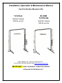
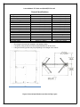
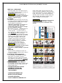
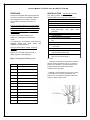
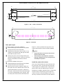
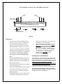
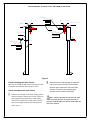
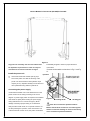
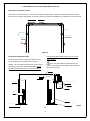
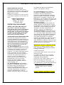
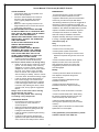
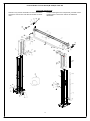
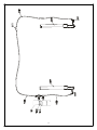
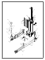
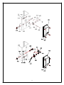
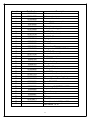
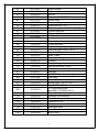
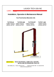
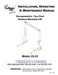
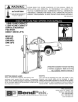
W-10DE Certified Automotive Lift W-10DE Certified Installation & Operation Manual 10,000 lb. Capacity Automotive Lift Derek Weaver Company, Inc. 2944 SE Loop 820 Fort Worth, TX 76140 817-560-9510 www.derekweaver.com Installation, Operation & Maintenance Manual Two Post Surface Mounted Lifts TLT210-A 10,000 lbs. Capacity 2,500 lbs. per Arm W-10DE TLT210-AS 10,000 lbs. Capacity 2,500 lbs. per Arm 1820 S Milliken Ave. Ontario, California 91761 Tel: 562 463-1580 Fax: 562 463-1590 www.launchtechusa.com IMPORTANT: READ THIS MANUAL COMPLETELY BEFORE INSTALLING OR OPERATING LIFT Launch Models TLT210-A and (W-10DE)TLT210-AS General Specifications See Figure 1 A. Lifting Height B. Column Height C. Cylinder Full Height D. Total Width E. Drive-Thru Clearance F. Floor to Overhead Switch G. Front Arm Reach (min / max) H. Rear Arm Reach (min / max) I. Screw Pad Height J. Inside Column Width Motor Voltage Rise Speed Max. Load Per Arm Ceiling Height Required Narrow Bay Setting TLT210-A 76.4" (1940mm) 148.8" (3780mm) 145.2" (3688mm) 137.9" (3502mm) 92" (2338mm) 145" (3683mm) 23.6" 9600mm) / 43.5" (1105mm) 38.6" (980mm) / 61.8" (1570mm) 4" (101mm) to 7.5" (190mm) 101.9" (2588mm) 2 HP 208-230Volt/Single Phase 54 Seconds 2500 Lbs. 149.5" (3797mm) Deduct 5.9" (149mm) (W-10DE)TLT210-AS 76.4" (1940mm) 148.8" (3780mm) 145.2" (3688mm) 136.6" (3470mm) 98.4" (2500mm) 145" (3688mm) 23.6" 9600mm) / 43.5" (1105mm) 38.6" (980mm) / 61.8" (1570mm) 4" (101mm) to 7.5" (190mm) 110.2" (2800mm) 2 HP 208-230Volt/Single Phase 54 Seconds 2500 Lbs. 149.5" (3797mm) Deduct 5.9" (149mm) Rise height measured with footpads in the highest position. Lift capacity rating is based on loads equally distributed on all four arms. Lifting and lowering speeds may vary depending on the weight of the vehicle . Figure 1-General Specifications and Service Bay Layout Launch Models TLT210-A and (W-10DE)TLT210-AS VERTICAL CLEARANCE Check the height of the area where the lift is to be installed. Clearance should be based on the full raised height of the lift. WARNING! Failure by purchaser to provide adequate clearance could result in unsatisfactory lift performance, property damage, or personal injury. Safety decals similar to those shown here are found on a properly installed lift. Be sure that all safety decals have been correctly installed on the Power Unit reservoir. Verify that all authorized operators know the location of these decals and fully understand their meaning. Replace worn, faded, or damaged decals promptly. FLOORING Be certain you have the proper concrete floor to properly handle the loaded lift. Floor should be in generally good condition with no large cracks, spalling or deterioration. **Minimum requirements for concrete are 4 inches minimum depth, with steel reinforcement, 3500 psi, cured for 28 days per local commercial practice. Minimum anchor imbedment of 3 ¼” is required for proper installation. If more than 2 ¼” of bolt is above floor grade You DO NOT have enough i m b e d m e n t . Floor should be level within 3/8 inch over the installation area. No anchors should be installed within 8 inches of any crack, edge, or expansion joint. If these conditions cannot be met, a pad may be poured to accommodate the lift. Check with local building inspectors’ and permits office for any special instructions or approvals required for your installation. WARNING! Failure by purchaser to provide the recommended mounting surface could result in unsatisfactory lift performance, property damage, or personal injury. LOCATION This lift has been evaluated for indoor use only with an operating ambient temp. range of 5 - 40°C (41-104°F) ELECTRICAL REQUIREMENTS For lift installation and operation for single phase units, it is necessary to have a dedicated circuit with a double pole 25 amp circuit breaker or time delay fuse. All electrical connections should be performed by a licensed electrician. SAFETY NOTICES AND DECALS For your safety, and the safety of others, read and understand all of the safety notices and decals included here. READ ENTIRE MANUAL BEFORE ASSEMBLING, INSTALLING, OPERATING, OR SERVICING THIS EQUIPMENT. PROPER MAINTENANCE AND INSPECTION IS NECESSARY FOR SAFE OPERATION DO NOT OPERATE A DAMAGED LIFT WARNING! Do not attempt to raise a vehicle on the lift until the lift has been correctly installed and adjusted as described in this manual. Launch Models TLT210-A and (W-10DE)TLT210-AS RECEIVING INSTALLATION The shipment should be thoroughly inspected as soon as it is received. The signed bill of lading is acknowledgement by the carrier of receipt in good condition of shipment covered by our invoice. wear safety glasses while installing lift. SUGGESTED TOOLS (Minimum Required) Tape measure, 16ft Chalk line 4ft level 10" adjustable wrench Metric open end wrenches 10mm, 13mm,14mm,15mm, 17mm, 18mm, 19mm and 24mm Needle Nose pliers Snap Ring pliers Screw Drivers (Flat and Phillips) Hammer drill with 3/4" diameter carbide tipped bits 2 lb. hammer Torque wrench: 150 foot pounds minimum with 1 1/8" socket 12 ft. Step ladder Anti-Seize lubricant (for arm pins and foot pad screw threads and stop rings) Hydraulic line sealant (Do not use Teflon tape…this can cause leaking.) If any of the goods called for on your bill of lading are shorted or damaged, do not accept them until the carrier makes a notation on the freight bill of the missing or damaged goods. Do this for your own protection. Contact Launch Lift immediately if any hidden loss or damage is discovered after receipt. IT IS DIFFICULT TO COLLECT FOR LOSS OR DAMAGE AFTER YOU HAVE GIVEN THE CARRIER A CLEAR RECEIPT. File your claim with the freight company promptly. Support your claim with copies of the bill of lading, freight bill, and photographs. Major Component Packing List Qty. Description 1 Power Side Column 1 Idler Side Column 2 Overhead Beams 2 Column Extensions 2 Rear Arm Assemblies 2 Front Arm Assemblies 2 Cable Assemblies 1 Hardware Box 1 Hydraulic Hose Kit 2 Lock Covers 1 Hydraulic Power Unit 1 Document Packet 4 Foot Pad Extensions IMPORTANT: Always LAYOUT * Layout the service bay according to the architect's plans or owners instructions (see Fig 1). Failure to install in this orientation can result in personal and property damage. Be certain that the proper conditions exist, see page 3. * Assemble column extension to each column using (12 sets) M12 x 35 Hex bolts, flat washers, lock washers and nuts. Repeat for opposite column and extension. Refer to Fig. 2 below. Figure 2 Launch Models TLT210-A and (W-10DE)TLT210-AS A 1# 2# 136.6″(3470mm) 2.8″(70mm) 15.7″(400mm) 104.7″(2660mm) 3 B C 4 113″(2870mm) Figure 3 ( W - 1 0 D E ) TLT210-AS A 1# 2# 5.16″(131mm) 137.9″(3502mm) B D E C 8.98″ (228mm) 8.98″ ) (228mm 119.9″(3046mm) Figure 4 TLT210-A Base plate layout As shown in Figure 3 (symmetric installation). With total width (A) as the basis, draw two parallel length of L, which is parallel to M to get point E. The column relative position could be located by ABCDE. lines (#1 and #2) on the concrete slab. Determine the power side column location on any Notes: chalk line, and mark the total width (B) of the base All the dimensions are based on the external plate. Mark the points 3 and 4. border of the base plate. Starting from point 3, draw one diagonal line (C) to The lift layout is very important. If not done the point 5 forming a triangle. In this way, the #1 and properly, problems may occur during the final #2 lines can determine the location of the two assembly and operation. columns. For asymmetric installation see Figure 4. With total width (A) as the basis, draw two parallel lines (#1 and #2) on the concrete slab. Mark any point on line #1 as point B. Take B as a base point, then move downward with 131mm and rightward with 228mm to get point C. Take B as a base point, and then draw a line M with same length of A, which is perpendicular to B to get point. Take as a base point, and then draw a line N with same Install the power side column First connect and assemble the column extension with the power side column, and then raise the power side column upright to the chalked location. Align the base plate of column with the chalk line layout. Using the baseplate as a template, drill holes into the concrete slab and use the five concrete anchor bolts to attach the column to the floor. During the drilling process, do not allow any movement of the column from the chalk line. Launch Models TLT210-A and (W-10DE)TLT210-AS Column Column 250mm (9.8in) M19×140 anchor bolts Foundation concrete intensity above3000PSI(2.1Kg/mm 2 ) 2 (5.9in) 150mm 4000mm(157.5in) wide:1800mm(70.9in) φ19mm(φ0.75in) Dilled hole Expand Clean Fasten Figure 5 Anchoring The anchor bolts must be installed at least 8” and washer contact the baseplate. away from any crack, edge, or expansion joint. Use a concrete hammer drill with a ¾ inch carbide bit. The tip diameter should conform to ANSI Standard B94.12-1988 (.775 to .787). Do not use any excessively worm bits or bits which have been incorrectly sharpened. A core bit may be necessary if obstructions such as steel rebar or rocks are encountered. Never substitute with a shorter or incorrect diameter anchor bolt. Recheck overall width dimension, fig. 3 or fig. 4. Drill the anchor holes using the baseplate as a template. Drill through the floor if possible or at least 6 inches minimum. Vacuum the dust from the hole to ensure proper anchor bolt holding power. Shim column to plumb using the shims provided. Do not shim more than ½ inch at any given point. Use a 24 inch or larger level in length to plumb the columns. Assemble the washer and nut to anchor with the nut just below the impact section of the bolt. Drive the anchor bolt into the hole until the nut Tighten the anchors and recheck the column for plumb. Re-shim if necessary. Using a torque wretch only, tighten to 150 foot lbs. Do not use an impact gun to tighten the anchor bolts. Minimum anchor imbedment of 3 ¼” is required for proper installation. If more than 2 ¼” of bolt is above floor grade You DO NOT have enough imbedment Installing the overhead beam After attaching the column extension to the idler column, position the idler column at the designated chalk location. Lift the overhead beam to its highest position and use the fasteners to attach it to the columns (as shown in Fig. 6). When installing the overhead beam, ensure the microswitch support adjacent to the power side column is positioned at the power side column location. Route the microswitch cord through the end of the overhead beam and down the outside of the column as shown in Fig. 11. . Note: Since the idler column is not secured to the floor by the bolts at this stage, be careful to not move the idle column as it could tilt over. Launch Models TLT210-A and (W-10DE)TLT210-AS 8-M12×35 Bolt 16-12 Flat washer 2 8-12 Spring washer 1 8-M12 Nut 1" 2" Connecting bracket Top sheave T op pulley Top beam 6-M10×20 Bolt Extension column 6-12 Flat washer 6-12 Spring washer Column 16-M12× 35 Bolt 32-12 Flat washer 16-12 Spring washer 16-M12 Nut Figure 6 Finish installing the idler column Drill holes and install the idler column following the same procedures as outlined for the power side column. Install and adjust the steel cables Adjust the tension of cables through the adjustment nuts on each end of steel cable. The steel cables should be tight in equal tension. Each steel cable should be in the sheave when adjusting tightly, otherwise the steel cable will be damaged. Raise the two carriages to the safety locking position (make sure that the safety locks on each column are fully engaged before attempting to install cables), and the two carriages are in equal position from the floor (same height). Install the two steel cables as shown in Fig. 7. Note: Before operating the lift check the steel cables and verify they are not intersected and are properly installed. Make sure that the steel cables are still on the sheaves. Launch Models TLT210-A and (W-10DE)TLT210-AS Figure 7 Key points for assembly: the two steel cables shall immediately stopped to check for proper electrical be adjusted to equal tension in order to verify the connections. simultaneous movement of the two carriages. * Connect the microswitch cord as shown in Fig. 11 and Fig. 12. Install the power unit Up button Use 5/16x18 bolts and washers (see fig. 8) to secure the power unit. After the securing of the power unit. Fill the reservoir with hydraulic oil (oil capacity of 10L). Operate carefully to avoid dust and other pollutants mixing with the hydraulic oil. Connecting the power supply * Dismantle the sealed cover of the electrical box on the power unit and do the wiring according to the circuit diagram. A power supply switch is required to be installed Figure 8 near the lift for rapidly disconnecting the power supply Lowering handle Oil filling port during maintenance or in case of emergency. Motor damage caused by improper wiring is not warranted. Note: Do not install this product outdoors. Verify that the oil tank is full; do not operate if there is no Motors and electrical controls are not sealed against oil. After pressing the up button, if the motor doesn’t run weather or moisture. Damage or electrical shock may or abnormal noise or heat occurs, the power unit shall be occur if installed unprotected outdoors. 9 Launch Models TLT210-A and (W-10DE)TLT210-AS Install the Lock Release Cable Raise lift to a lock position but do not set onto lock. Pull and release power column lock release handle and watch the idler column lock. Adjust cable tension by removing slack in the cable and retightening the cable clamp at the power side. Latch cable guide Steel cable Idler column P owerside column Nylon roller Offside column Nylon wheel Figure 9 Connect the hydraulic lines Improperly installed hydraulic fittings are not covered Install all hydraulic lines and fittings as shown in fig.10. under warranty Clean all piping and hose threads and inspect for Note: If the hose shall be installed through the damage. Use oil resistant pipe sealant on all the threads column, ensure that the hose passage will not interfere and tighten properly. Do not use Teflon tape. It is the with any moving parts. installers’responsibilitytoinsure the system is leak free. Hose ¢10 Spring washer ¢10 Flat washer M10×25 Bolt 2 sets Column Turn around fitting T fitting Power unit 油缸 Cylinder Hose Flow control fitting Flow control fitting Figure 10 10 Launch Models TLT210-A and (W-10DE)TLT210-AS Proper installation of the overhead microswitch electrical cord It is very important to keep proper clearance between microswitch electrical cord and the steel cable. Use the provided plastic ties to connect the electrical cord and hose together to avoid any possible damage caused by interference between the electrical cord and the steel cable. Microswitch Electrical Cord Steel Cable Plastic Tie Hose Figure 11 10 Figure 12 10 Launch Models TLT210-A and TLT210-A are qualified and that they are adequately trained in the inspection of the lift. OWNER/OPERATOR CHECKLIST Demonstrate the operation of the lift to the owner/operator and review the correct and safe lifting procedures using the provided Lifting It Right booklet as a guide. The Owner/Employer shall establish procedures to periodically maintain the lift in accordance with the lift manufacturer's instructions or ANSI/ALIOIM-2000, American National Standard for Automotive Lifts-Safety Requirements for Operation, Inspection and Maintenance; and the employer shall insure that the lift maintenance personnel are qualified and that they are adequately trained in the maintenance of the lift. The Owner/Employee shall maintain the periodic inspection and maintenance records recommended by the manufacturer or ANSI/All ALOIM-2000, American National Standard for Automotive Lifts-Safety Requirements for Operation, Inspection and Maintenance. The Owner/Employer shall display the lift manufacturer's operating instructions; ALI/SM 93 -1, ALI Lifting it Right safety manual; ALI/ST90 ALI Safety Tips card; ANSI/All ALOIM-2000, American National Standard for Automotive Lifts- Safety Requirements for Operation, Inspection and Maintenance; and in the case of frame engaging lift, ALI/LP-GUIDE, Vehicle Lifting Points/Quick Reference Guide for Frame Engaging Lifts; in a conspicuous location in the lift area convenient to the operator. Complete the installation and review the terms of the warranty registration card and return the card to: Launch Tech USA Inc. 1820 S. Milliken Ave. Ontario, CA. 91761 1-562-463-1580 OPERATION PROCEDURE SAFETY NOTICES AND DECALS This product is furnished with graphic safety warning labels, which are reproduced on page 2. Do not remove or deface these warning labels, or allow them to be removed or defaced. For your safety, and the safety of others, read and understand all of the safety notices and decals included. OWNER/EMPLOYER RESPONSIBILITIES This lift has been designed and constructed according to ANSI/All ALCTV-2006 standard. The standard applies to lift manufactures, as well as to owners and employers. The owner/employer's responsibilities as prescribed by ANSI/All ALOIM2000, are summarized below. For exact wording refer to the actual standard provided with this manual in the literature package The Owner/Employer shall insure that lift operators are qualified and that they are trained in the safe use and operation of the lift using the manufacturer's operating instructions; ALI/SM 93 -1, ALI Lifting it Right safety manual; ALI/ST- 90 All Safety Tips card; ANSI/ALI ALOIM-2000, American National Standard for Automotive Lifts- Safety Requirements for Operation, Inspection and Maintenance; ALI/WL Series, ALI Uniform Warning Label Decals/Placards; and in case of frame IMPORTANT SAFETY INSTRUCTIONS When using your garage equipment, basic safety precautions should always be followed, including the following: 1.Read all instructions. 2.Care must be taken as burns can occur from touching hot parts. 3.To reduce the risk of fire, do not operate equipment in the vicinity of open containers of flammable liquids (gasoline). 4.Keep hair, loose clothing, fingers, and all parts of body away from moving parts. 5.Use only as described in this manual. Use only manufacturer’s recommended attachments. 6.ALWAYS WEAR SAFETY GLASSES. Everyday eyeglasses only have impact resistant lenses, they are not safety glasses. engaging lifts, ALI/LP-GUIDE, Vehicle Lifting Points/Quick Reference Guide for Frame Engaging Lifts. The Owner/Employer shall establish procedures to periodically inspect the lift in accordance with the lift manufacturer's instructions or ANSI/All ALOIM-2000, American National Standard for Automotive Lifts-Safety Requirements for Operation, Inspection and Maintenance; and the employer shall insure that the lift inspectors SAVE THESE INSTRUCTIONS 10 Launch Models TLT210-A and (W-10DE)TLT210-AS LIFTING A VEHICLE Insure that the lifting arms are parked out to the full drive thru position. Center the vehicle between the columns in the service bay and position the vehicle's center of gravity midpoint between the columns. NOTE: the center of gravity is based on the weight distribution and is not the same as the center point of the vehicle. DO NOT EXCEED 2500 POUNDS PER ARM. DO NOT ATTEMPT TO LIFT A VEHICLE WITH ONLY ONE OR TWO ARMS, THIS IS UNSAFE AND WILL VOID THE WARRANTY. INSURE THAT THE HIGHEST POINT ON THE VEHICLE WILL CONTACT THE OVERHEAD LIMIT SWITCH BAR. DO NOT PLACE THE VEHICLE IN THE SERVICE BAY BACKWARDS. REFER TO THE VEHICLE MANUFACTURERS SERVICE MANUAL, TECHNICAL BULLETINS, THE "VEHICLE LIFTING POINTS GUIDE" (ALIILP-GUlDE) THAT IS INCLUDED WITH THE LIFT OR OTHER PUBLICATIONS TO LOCATE THE RECOMMENDED LIFTING POINTS. Position the arms and adapters so all four pads contact the vehicle simultaneously. The vehicle should remain level during lifting. Raise the lift until all four wheels are off the ground. Test the stability of the vehicle by attempting to rock the vehicle. Check the adapters for secure contact with the vehicle lift points. If the vehicle seems unstable, lower the vehicle and re-adjust the arms. After re-testing for stability, raise the vehicle 2-3 inches above the desired working height. MAINTENANCE To avoid personal injury, permit only qualified personnel to perform maintenance on this equipment. Maintenance personnel should follow lockout /tag out instructions per ANSI Z244.1. The following maintenance points are suggested as the basis of a routine maintenance program. The actual maintenance program should be tailored to the installation. See ANSI/All ALOIM booklet for periodic inspection checklist and maintenance log sheet. If lift stops short of full rise or chatters, check fluid level and fill per installation instructions. Replace all Safety, Warning or Caution Labels if missing or damaged (See installation instructions page 2). Daily Keep lift components clean. Check for loose or broken parts. Check hydraulic system for fluid leaks. Check adapters for damage or excessive wear. Replace as required with genuine Launch Lift parts. Check lock release activation. When properly adjusted, the idler column lock should rest firmly against the back of the column when engaged and pull clear of the column back when disengaged. Weekly Check synchronizer cables and sheaves for wear. Replace as required with genuine Launch Lift parts. Lower the vehicle until the safety latches on both columns engage. The vehicle should remain level when both latches are engaged. If one side engages and the other continues to descend, stop lowering the vehicle, raise it several inches, and try again to engage both latches. Always lower lift into locks before entering the area beneath the vehicle. Always use safety stands when removing or installing heavy components. Check lock release cable adjustment per installation instructions. Check synchronizer cable tension per installation instructions. Adjust if necessary. Monthly Torque all concrete anchor bolts to 150 ft-Ibs. Check overhead shutoff switch. While raising lift, operate overhead shutoff bar. Power Unit motor should stop when bar is raised. LOWERING A VEHICLE Insure that the area under the vehicle is clear of personnel, tools, toolboxes or service equipment. Raise the vehicle until both latches are free. Disengage the latches by pulling down and holding the lock release lever. Lower the vehicle by depressing the lowering valve handle. Continue to lower until the carriages stop against the base plate. Retract the extension arms, and move them away from the vehicle. Lubricate carriage slide tracks with heavy viscous grease. (Grease all (4) corners of both columns.) Visually inspect concrete floor for cracks and/or spalls within 12" of base plate. If any problems are encountered, please contact Launch Tech USA, Inc. 10 Launch Models TLT210-A and (W-10DE)TLT210-AS List of lift components This list is only used as information for the maintenance and repair. Launch Tech USA will not be liable for other uses. In case of damages to the components, purchase can be made from the Launch Tech USA or its authorized distributors. 12 13 201 205 235 206 207 204 226 209 227 208 202 228 230 223 231 215 234 229 217 233 210 216 214 232 224 211 218 212 213 225 221 220 219 222 12 13 Location 1 3 4 5 6 7 8 9 10 11 12 13 14 15 16 17 18 19 20 21 22 23 24 25 26 27 28 29 30 31 32 33 34 35 36 37 38 Part Number 201024604 201014670 201024608 103201070 103010432 103040132 201013268 103020188 201011739 103020164 103040044 103040110 103030129 103040123 103040122 103020207 201011740 201011154 103020100 103040134 103040141 103020171 201024606 103020163 201021179 201020809 201011257 103200699 201013282 103050035 103200966 201011258 103200967 103020126 201014671 104130196 Description Column Column extension Power unit bracket Column bottom cover plate screw M5*12 Flat washer Lateral positioning palte BoltM5×10 Connection bracketⅠ Bolt M12×35 Spring washer Flat washer Nut M12 Flat washer 10 Spring sealer, GB/T93-1987 11 Bolt M10×20 Connection bracketⅡ Reinforcement plate Bolt M8X25 Flat washer 8 Spring washer, 8 Bolt M6×12 Cable guide block Bolt M6X25 Outer overhead beam bracket Inner overhead beam bracket Sheave Spacer, Power Side, 8mm Bush, SF-2 2520 Sheave Elastic ring, 25,GB/T894.1-1987 Asymmetric shaft Spacer I Symmetric shaft Bolt Shutoff bar Sleeve(inner holeФ22),L=1.8M Limit switch TS-10 14 39 40 41 42 43 44 45 46 47 48 49 201014672 201014673 103030018 103060342 201011477 103260260 103020117 201014674 201014675 201014676 201014685 Switch bracket Switch shaft Nut M5 Cotter pin 3*26,GB91-87 Shutoff shaft Cable assembly Anchor bolt M19*140 Column long hood at three-way fitting Column long hood Column short hood Shaft for Hose hood 101 102 103 104 105 106 107 109 111 112 104120132 103202113 104120134 103100294 104120133 103100322 103202112 103100295 104120135 Power unit Power unit hose Adjustable right angle fitting Overhead beam hose, L=5370 Three-way fitting Hose, L=980 Flow control fitting assembly Cylinder Straight fitting Idler column hose L=4250 201 202 204 205 206 207 201024611 104990132 201011855 103010473 103040122 103040123 208 104130191 209 210 211 212 213 214 215 216 103010539 103202184 103060376 103060355 103201914 103201744 201010982 103010443 Carriage TLT235SB Slide block, strengthen nylon Top board Screw M10x30 Spring sealer, GB/T93-1987 11 Ring GB/T95-1985 11 TLT235SB Anti-shock pad,SBR,TLT235SB-20-03-A Screw M8×12 Restraint shaft assembly Pin 5*32 Cotter pin,3.2*30 Spring Small gear block Pin shaft Bolt M10x25 15 217 218 219 220 221 222 223 224 225 226 227 228 229 230 231 232 233 234 103201771 103050030 201021763 104130186 103010608 201021532 201024616 201024645 201024646 104130315 201021561 103202107 103202106 103050091 103050090 201014690 201014691 201011475 103010586 201011741 235 201011742 401 402 403 404 405 406 407 408 409 412 413 414 415 416 417 104090074 201012086 201020584 103201450 103201451 103201455 202010074 103201454 103260186 201011156 104130210 103050021 103060333 103260179 101060019 Big gear block Retaining ring 40 Long female arm Arm rubber pad Bolt M6x10 Long male arm Front female arm Front middle arm Front male arm Rubber pad Threaded rod assembly Dual-threaded adjustment sleeve Support bracket Retaining ring,30 Retaining ring,45 Long extension tube(optional) Short extension tube(optional) Positioning plate Bolt M8×12-12.9 Asymmetric adjustable bushing for asymmetric installation Adjustable bushing for narrow style installation Lock release mechanism hood Lock release plate Cam (Power side) Torsion springⅠ Torsion spring Ⅱ Lock release plate shaft Lock Release roller Lock release latch Latch cover BM10×50(black) Adjustment washer I Small rubber pad Retaining ring 9 Pin, 6*40 Cable Clamp 3 Cable,Φ1.4,L=8901 16 418 419 420 421 422 103201478 103050025 103010393 103040134 104090073 Cable clamp φ2 Retaining ring 20 Screw,M8*12 Washer C,8 Idler lock release mechanism hood 17 Maintenance Records Form #TLT210 1012011 18