1
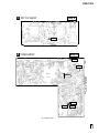
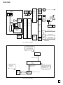
PureCinema Progressive
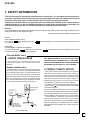
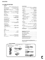
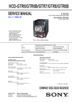
DVD RECORDER DVR-7000
SMART JOG
DVD
FL OFF
2DIGITAL
Î
TIMER
AUTO REC
STANDBY/ON
OPEN/CLOSE
FL DIMMER
0
DISCNAVI
OPEN
7 STOP
FUNCTION
3 PLAY
8 PAUSE
REC
DVD RECORDER
DVR-7000
THIS MANUAL IS APPLICABLE TO THE FOLLOWING MODEL
Type
Model
DVR-7000
KU/CA
Power Requirement
AC120V
Region No.
Remarks
1
CONTENTS
1. SAFETY INFORMATION ........................................ 2
2. ADJUSTMENT ........................................................ 4
3. GENERAL INFORMATION ................................... 8
3.1 DIAGNOSIS .................................................... 8
3.1.1 MODEL TYPE AND REGION SETTING ..... 8
3.1.2 CPRM ID NUMBER AND ID DATA SETTING ..... 9
3.1.3 DEBUGGING MENU ............................. 11
3.1.4 SERVICE MODE ................................... 17
3.1.5 POWER ON SEQUENCE ..................... 18
3.1.6 DISASSEMBLY ..................................... 19
3.2 OUTLINE OF THE PRODUCT ..................... 22
4. PANEL FACILITIES AND SPECIFICATIONS ..29
PIONEER CORPORATION
4-1, Meguro 1-chome, Meguro-ku, Tokyo 153-8654, Japan
PIONEER ELECTRONICS (USA) INC. P.O. Box 1760, Long Beach, CA 90801-1760, U.S.A.
PIONEER EUROPE NV Haven 1087, Keetberglaan 1, 9120 Melsele, Belgium
PIONEER ELECTRONICS ASIACENTRE PTE. LTD. 253 Alexandra Road, #04-01, Singapore 159936
PIONEER CORPORATION 2001
DVR-7000
1. SAFETY INFORMATION
This service manual is intended for qualified service technicians ; it is not meant for the casual do-ityourselfer. Qualified technicians have the necessary test equipment and tools, and have been trained
to properly and safely repair complex products such as those covered by this manual.
Improperly performed repairs can adversely affect the safety and reliability of the product and may
void the warranty. If you are not qualified to perform the repair of this product properly and safely, you
should not risk trying to do so and refer the repair to a qualified service technician.
WARNING
This product contains lead in solder and certain electrical parts contain chemicals which are known to the state of California to cause
cancer, birth defects or other reproductive harm.
Health & Safety Code Section 25249.6 – Proposition 65
NOTICE
(FOR CANADIAN MODEL ONLY)
Fuse symbols
(fast operating fuse) and/or
be of identical designation.
(slow operating fuse) on PCB indicate that replacement parts must
REMARQUE
(POUR MODÈLE CANADIEN SEULEMENT)
Les symboles de fusible
(fusible de type rapide) et/ou
de remplacement doivent avoir la même désignation.
(fusible de type lent) sur CCI indiquent que les pièces
(FOR USA MODEL ONLY)
1. SAFETY PRECAUTIONS
The following check should be performed for the
continued protection of the customer and service
technician.
ANY MEASUREMENTS NOT WITHIN THE LIMITS
OUTLINED ABOVE ARE INDICATIVE OF A POTENTIAL
SHOCK HAZARD AND MUST BE CORRECTED BEFORE
RETURNING THE APPLIANCE TO THE CUSTOMER.
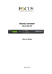
LEAKAGE CURRENT CHECK
Measure leakage current to a known earth ground (water
pipe, conduit, etc.) by connecting a leakage current tester
such as Simpson Model 229-2 or equivalent between the
earth ground and all exposed metal parts of the appliance
(input/output terminals, screwheads, metal overlays, control
shaft, etc.). Plug the AC line cord of the appliance directly
into a 120V AC 60Hz outlet and turn the AC power switch
on. Any current measured must not exceed 0.5mA.
Reading should
Leakage not be above
current 0.5mA
tester
Device
under
test
Test all
exposed metal
surfaces
Also test with
plug reversed
(Using AC adapter
plug as required)
Earth
ground
2. PRODUCT SAFETY NOTICE
Many electrical and mechanical parts in the appliance
have special safety related characteristics. These are
often not evident from visual inspection nor the protection
afforded by them necessarily can be obtained by using
replacement components rated for voltage, wattage, etc.
Replacement parts which have these special safety
characteristics are identified in this Service Manual.
Electrical components having such features are identified
by marking with a on the schematics and on the parts list
in this Service Manual.
The use of a substitute replacement component which does
not have the same safety characteristics as the PIONEER
recommended replacement one, shown in the parts list in
this Service Manual, may create shock, fire, or other hazards.
Product Safety is continuously under review and new
instructions are issued from time to time. For the latest
information, always consult the current PIONEER Service
Manual. A subscription to, or additional copies of, PIONEER
Service Manual may be obtained at a nominal charge from
PIONEER.
AC Leakage Test
2
DVR-7000
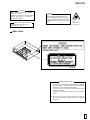
IMPORTANT
THIS PIONNER APPARATUS CONTAINS
LASER OF CLASS 1.
SERVICING OPERATION OF THE APPARATUS
SHOULD BE DONE BY A SPECIALLY
INSTRUCTED PERSON.
LASER DIODE CHARACTERISTICS
MAXIMUM OUTPUT POWER : 35 mw
WAVELENGTH : 658 nm
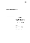
WARNING!
DEVICE INCLUDES LASER DIODE WHICH
EMITS INVISIBLE INFRARED RADIATION
WHICH IS DANGEROUS TO EYES. THERE IS
A WARNING SIGN ACCORDING TO PICTURE
1 INSIDE THE DEVICE CLOSE TO THE LASER
DIODE.
LASER
Picture 1
Warning sign for
laser radiation
LABEL CHECK
Printed on Rear Panel
DRW2069
Additional Laser Caution
1. The ON/OFF(ON:low level,OFF:high level) status of the
CLAMP signals for detecting the loading state are detected
by the drive CPUs, and the design prevents laser diode
oscillation when the CLAMP signal turns OFF.
In normal operation, if no disc is clamped, the laser diode
oscillation is disabled.
However, the interlock does not always operate in the test
mode. *
2. When the cover is opened, close viewing of the objective
lens with the naked eye will cause exposure to a Class 3A
laser beam.
* Refer to pages 43 of DVR-A03 Service Manual(RRV2423).
3
DVR-7000
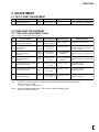
2. ADJUSTMENT
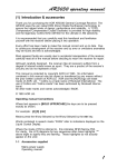
2.1 3D Y/C ASSY ADJUSTMENT
No.
1
Adjustment Name
Y/C input level adjustment
(Input system adjustment)
Adj. Point Measurement Point
VR3301
TUMJ ASSY
CN3001 Pin10(SEL Y)
Adjustment Value
2.00Vp-p ± 80mV
Adjustment State
Input a white 100%(1.0Vp-p) signal into
Input 1 (composite). (75Ω termination)
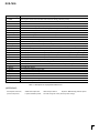
2.2 TUMJ ASSY ADJUSTMENT
2.2.1 TUMJ ASSY ADJUSTMENT TABLE
Note : Use disc : [ DVD test disc GGV1025]
No.
Adjustment Name
Adj. Point Measurement Point
Adjustment Value
Adjustment State
2.00Vp-p ± 80mV
Input a signal of fv=EIA color-bar 60dBµV to
terrestrial wave input. /through output.
Audio ouput (R)
(Rear panel)
310mVrms± 9.3mV
Input a signal of Mono 1kHz/100% modulation
to terrestrial wave input. /through output.
(Rec level = ± 0) Note 2
Audio multiplex WIDE BAND adjustment IC4601
(Input system adjustment)
(IIC bus adj.)
Refer to 6.2.2.
Audio ouput (R)
(Rear panel)
Input a signal of Stereo 300Hz/30% modulation
Best point of separation
(NR-ON) to terrestrial wave input. /through output
≥30dB Note 1
Note 2
4
Audio multiplex SPECTRAL adjustment
IC4601
(Input system adjustment)
(IIC bus adj.)
Refer to 6.2.2.
Audio ouput (R)
(Rear panel)
Input a signal of Stereo 3kHz/30% modulation
Best point of separation (NR-ON) to terrestrial wave input. /through output
≥25dB Note 1
Note 2
5
Y level adjustment of component system
(Output system adjustment)
VR1311
Component ouput (Y)
(75Ω terminate)
1.0Vp-p ± 40mV
100% white data playback
(DVD-REF-A1 T2-C5,etc)
6
PB level adjustment of component system
(Output system adjustment)
VR1313
Component ouput (PB)
(75Ω terminate)
714mVp-p ± 28mV
100% white data playback
(DVD-REF-A1 T2-C19,etc)
7
PR level adjustment of component system
(Output system adjustment)
VR1312
Component ouput (PR)
(75Ω terminate)
714mVp-p ± 28mV
100% white data playback
(DVD-REF-A1 T2-C19,etc)
1
Video level adjustment of terrestrial
wave (Input system adjustment)
2
Audio multiplex ATT adjustment (Input
IC4601
system adjustment)
(IIC bus adj.)
Refer to 6.2.2.
3
VR4101
TUMJ ASSY
CN3001 Pin10(SEL Y)
Note 1 : The values for channel separation is defined as those having passed through the following filters :
100Hz – 10kHz : +0/–0.5dB
15.75kHz – 100kHz : -40dB or more
Note 2 : The audio multiplex adjustment No.2 – No.4 is done under the debugging mode.
Refer to 6.2.2 about the details.
4
DVR-7000
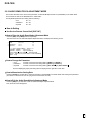
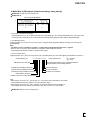
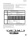
2.2.2 AUDIO DEMULTIPLEX ADJUSTMENT MODE
This section describes how to set the each parameter of US Audio Multiplex Decoder IC (CXA2094Q) on the TUMJ ASSY
and memorize the data on the EEPROM in the TUMJ ASSY.
The adjustable parameters and setting data are following :
• ATT
00 ~ 15
• Wideband
00 ~ 63
• Spectral
00 ~ 63
How to Setting
Use Service Remote Control Unit [GGF1067]
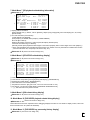
How to Enter the Audio Demultiplex Adjustment Mode
Press the [ESC] and [P.RUN] buttons sequentially.
Then the screen turns to Audio Demultiplex Adjustment Mode, and displays the following screen.
1
2
3
< Tuner Audio Separation Adjustment >
ATT
>>>>>>>>
09
Wideband
>>>>>
31
Spectral
>>>>>
31
*** How to operate ( [Button : Action] ) ***
[SPEED–, SPEED+ : Adjust ATT]
[SCAN<<, SCAN>> : Adjust Wideband]
[STILL STEP< , STILL STEP > : Adjust Spectral]
[PLAY : Memorize the present status on TUFL–EEPROM]
[ESC : Exit]
How to Change the Parameter
1 ATT
2 Wideband
3 Spectral
Increase or decrease the setting data by [SPEED+] or [SPEED–]
Increase or decrease the setting data by [SCAN>>] or [SCAN<<]
Increase or decrease the setting data by [STILL STEP >] or [STILL STEP< ]
The level display(bar-graph) and setting data are displayed at the right side of each item.
How to Memorize the Setting Data
Press the [PLAY] key of GGF1067 to memorize the data on the EEPROM in the TUMJ ASSY after setting each parameter.
(The data is not erased even if the AC plug is disconnected from the outlet.)
How to Exit the Audio Demultiplex Adjustment Mode
Press the [ESC] key of GGF1067 to exit the Audio Demultiplex Adjustment Mode.
Then the mode screen disappears.
5
DVR-7000
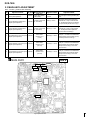
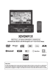
C
3D Y/C ASSY
SIDE A
VR3301
TUMJ ASSY
SIDE A
VR4101
10
IC4601
CN3001
1
A
VR1312
VR1311
VR1313
Fig1. Adjustment Point
6
DVR-7000
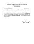
2.3 MAIN ASSY ADJUSTMENT
Note : Use disc : [ DVD test disc GGV1025]
No.
1
2
Adjustment Name
Master clock free-running adjustment
(Clock system adjustment)
Y level adjustment of CVBS system
(Output system adjustment)
Adj. Point Measurement Point
VC3001
Adjustment Value
27.000000MHZ
± 130Hz
Adjustment State
No input signal or during test disc playback
VR7006
Y output of S terminal 1.00Vp-p ± 40mV
(75Ω termination)
Playback the DVD test disc(100%white).
Terminate the Y output of S terminal with
75Ω and adjust so that the level of between
sync tip and white peak becomes 1.0Vp-p.
VR7007
C output of S terminal
(75Ω termination)
Playback the DVD test disc(100%color- bar).
Terminate the C output of S terminal with
75Ω and adjust so that the amplitude of
color burst becomes 286mVp-p.
MAIN ASSY
CN7001 Pin11
(Y Out)
800mVp-p ± 24mV
MAIN ASSY
CN7001 Pin13
(PB Out)
760mVp-p ± 22mV
3
C level adjustment of CVBS system
(Output system adjustment)
4
Y level adjustment of component system
(Output system adjustment)
VR7003
5
PB level adjustment of component system
(Output system adjustment)
VR7004
6
PR level adjustment of component system
(Output system adjustment)
VR7005
E
MAIN ASSY
IC4007 Pin54 (CLKO)
(M65774AFP)
286mVp-p ± 11mV
MAIN ASSY
CN7001 Pin15
(PR Out)
760mVp-p ± 22mV
MAIN ASSY
Playback the DVD test disc(100%white).
At the pin 11 of CN7001 in the MAIN ASSY,
adjust so that the level of between sync tip
and white peak becomes 0.8Vp-p.
Playback the DVD test disc(100%color- bar).
At the pin 13 of CN7001 in the MAIN ASSY,
adjust so that the level of between bottom
and top becomes 0.76Vp-p in the 100%
color-bar screen.
Playback the DVD test disc(100%color- bar).
At the pin 15 of CN7001 in the MAIN ASSY,
adjust so that the level of between bottom
and top becomes 0.76Vp-p in the 100%
color-bar screen.
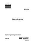
SIDE A
VR7004
VR7005
1
22
CN7001
VR7003
VR7007
VR7006
IC4007
54
VC3001
Fig.2 Adjustment Point
7
DVR-7000
3. GENERAL INFORMATION
3.1 DIAGNOSIS
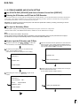
3.1.1 MODEL TYPE AND REGION SETTING
Setting the Model type and Region No. for DVD Recorder
For the DVD recorder DVR-7000/KU/CA and /LB type, it is necessary to set the region No. [1 or 3] on the FLASH ROM in
the MAIN ASSY and the model type [KU or LB] on the EEPROM in the TUMJ ASSY. So when the MAIN ASSY or TUMJ
ASSY is renewed, "The Model type and Region setting mode screen" is displayed automatically.
Note : If the region No. is once set, it is unable to rewrite it. When it is necessary to change the region No., renew the MAIN
ASSY. And it is able to rewrite the once set model type on the EEPROM in the TUMJ ASSY only when the MAIN ASSY is renewed and setting the new region No. on the FLASH ROM.
How to set the Model type and Region No.
1. Turn the power on.
2. The setting request screen is displayed when the model type and region No. is not set.
At this time FL displays " MODE SETTING".
[ Recorder's Model and Region Setting]
Please pick out any one of the following.
Button No.
Model
Region
[1
: KU_MODEL<North America> Region 1 ]
[2
: LB_MODEL <Taiwan>
Region 3 ]
3. Enter the data according to the mode menu by the service remote control unit.
4. The recorder restarts automatically.
5. Set the shipping position. (stop + power off)
But it is omitted when making the Down Load of the system µ-com is done after this.
6. Turn off the power, then turn on the power again.
When the FL displays "MODEL MISMATCH" after connecting the AC plug to the outlet.
It displays, connecting the AC plug to the outlet when the setting is mismatched between the software setting of the model
type data on the EEPROM and the µ-com hardware pin setting of the model type in the TUMJ ASSY.
At this time, it is unable to turn on the power.
↓
It is considered the TUMJ PCB board fault (model type hardware pin setting fault).
Note : [Tuner control µ-com hardware pin setting of the model type]
Pin 76=Region 1, Pin 77=Region 2, Pin 98=Region 3
Pull up the correspond pin to Vcc(V+3_3M) and pull down other setting pins to GND by 10kΩ resistor.
When the screen shows the following display after turning on the power
<display 1>
< Model and Region don't match >
Model [already memorized on the TUFL-EEPROM] : KU_MODEL
Region [already memorized on the MAIN-CPU-FLASH ROM] :3
model type information in the TUMJ ASSY
region information memorized in the MAIN ASSY
Please take the power-plug off
the plug socket
It displays, exchanging the MAIN ASSY or TUMJ ASSY,etc when the combination of model type and region No. already set
is mismatched.
After this, it is unable to operate any functions.
↓
Match the combination between the model type and region No. setting, or renew the ASSY and set the data newly.
When the screen shows the following display after setting the Model type and Region No.
<display 2>
< You can't change and overwrite the Region No. ! >
Region was already memorized on the MAIN-CPU-FLASHROM
and you can't overwrite the different Region.
Region[already memorized on the MAIN-CPU-FLASHROM] : 3
Model-Region[that you selected just now] : KU_MODEL -1
region information memorized in the MAIN ASSY
region information selected by the key input
at the setting mode screen
Please take the power-plug off
the plug socket.
It displays, renewing TUMJ ASSY,etc when setting the different model type from the region No. already set in the FLASH
ROM in the MAIN ASSY.
↓
Match the combination between the model type and region No. setting, or renew the MAIN ASSY and set the data newly.
8
DVR-7000
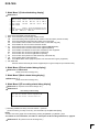
3.1.2 CPRM ID NUMBER AND ID DATA SETTING
Use ID DATA DISC [GGV1065] and Service Remote Control Unit [GGF1067]
Entering the ID Number and ID Data for DVD Recorder
For the DVD recorder,it is necessary with the recoding/playback of DVD–RW disc to set an individual number (ID number) and ID data to
each recorder. If the number and data are not set correctly with the following procedure, operations in the future may not be guaranteed.
You will find the ID number to be set on the ID label on the rear panel.
Important: If no ID label is found on the rear panel, write down the specified ID number by checking it according to "How to
confirm the ID number" shown below.
The Input is Necessary When:
• " CPRM ERR" is displayed on the FL display immediately after the power is turned on or in Stop mode.
• When the MAIN ASSY , RECORDER DRIVE MAIN, CPRM LSI or the FLASH ROM is exchanged.
Note:
Be sure to enter the ID number in Stop mode.
Use the service remote control (GGF1067) for operations. Only opening/closing of the tray are performed from the player.
The ID data disc is swept out automatically after the recorder have read the data from it.
How to Input the ID Number and ID Data
1 To enter the input mode, press ESC + STEREO in a status with
no ID number set, such as after FLASH-ROM downloading.
4 When the ID number has been registered, the unit enters the ID
data input mode. (The FL display indicates "INSERT ID DATA.")
In this condition, place the ID data disc on the tray and close the
tray using the CLOSE key "7/0" on the player.
[Recorder's ID Data Setting]
2 As number input is enabled when the unit enters the input
mode, input the 9-digit ID number.
(The entered number is also displayed on the FL display.)
2
[Recorder's ID Number Setting]
ID Number ?
>--------<CLEAR> Exit
<CLEAR> Exit
4
Insert The ID Data Disc !
Input ID Number !
5 While the data are being read, the message shown in the figure
at left is displayed on the screen.
(The FL display indicates "LOAD ID DATA.")
3 After inputting the number, press SEARCH to register the ID
number.
[Recorder's ID Data Setting]
[Recorder's ID Number Setting]
ID Number ?
> 0 0 0 0 0 0 0 0 1 OK ?
3
<PLAY>
Compare Mode
<SEARCH> Enter
5
Loading The ID Data Disc !
Input ID Number !
9
DVR-7000
6 When the ID data have been read, the data are written to the
FLASH-ROM.
(The FL display indicates "WRITE ID DATA.")
7 When the ID data have been written to the FLASH-ROM, the
message "Rom Write OK" is displayed on the screen.
(The FL display indicates "ID DATA OK.")
8 After confirming this message, press CLEAR to exit the input
mode.
[Recorder's ID Data Setting]
6
Wait Rom Writing !
[Recorder's ID Data Setting]
7
Rom Write OK !
8
<CLEAR> Exit
How to Confirm the ID Number
1 Press ESC + STEREO with an ID number set, and the unit
enters the ID number confirmation mode.
2 The set ID number is displayed on the screen (and on the FL
display), permitting you to confirm it.
3 To exit this mode, press CLEAR .
2
3
[Recorder's ID Number Setting]
ID Number ?
[ 0 0 0 0 0 0 0 0 1]
Compare
>*********
<CLEAR> Exit
Input ID Number !
How to Clear the ID Number
1 Press ESC + STEREO with an ID number set, and the unit
enters the ID number confirmation mode.
2 Input the same number as the ID number you have set.
2
[Recorder's ID Number Setting]
ID Number ?
[ 0 0 0 0 0 0 0 0 1]
Compare
>*********
<CLEAR> Exit
<STEREO> ID Data Setting Mode
Input ID Number !
3 After inputting the number, press STOP .
Only when the entered number matches the set ID number, the
ID number is cleared and the unit exits this mode.
If the numbers do not match, you must return to step 2.
( STOP is not accepted until 9 digits are entered.)
[Recorder's ID Number Setting]
ID Number ?
[ 0 0 0 0 0 0 0 0 1]
Compare
> 0 0 0 0 0 0 0 0 1 OK ?
3
<PLAY> Enter
<STOP> Memory Clear
<STEREO> ID Data Setting Mode
Input ID Number !
10
0
DVR-7000
3.1.3 DEBUGGING MENU
For operation, use the GGF1067 remote control unit for service.
The Debug menu is a main menu from which to select any of 11 mode menus, classified by rough category, such as recording
system and VR playback system. The mode menus also have subscreens if there are many items.
The Debug menu during playback of a DVD-V (including video mode), CD, or VCD is almost the same as that of the DV-737
(see Mode Menu 10).
How to Enter the Debug Menu
: Press [ESC] + [DISP] keys in order while no GUI is displayed.
How to Exit the Debug Menu
: Press the [ESC] key.
How to Advance the Mode Menu : Press the [DISP] key.
How to Advance the Subscreen in a Mode Menu : Press the [DIG/ANA] key.
Note 1 : If you press the [DISP] key on the final mode menu, the display will return to Mode Menu 1.
Note 2 : Pressing the [DIG/ANA] key repeatedly will change the subscreens within the same mode cyclically. To change mode
menus, press the [DISP] key.
Description of Each Mode
1. Mode Menu 1 [Version information, etc.]
Subscreen 1
1 DVR-7000 /KU
2
SYSCON :
3
:
4 TUFLCON
5
DRIVE
:
6
7
DEVICE
REGION
:
:
RELEASE_1 1 2
R e v : 1. 6 1 0 9. 2. 2 2 6. 2. 4
1. 5 2 0 0
PIONEER
DVD–RW DVR–7 0 0 0
1. 6 1 C
7911
AET0000224JP
AV1=ES6. 0
1
$
OK
OK
OK
OK: Correct combination
NG+: Version of the tuner microcomputer too high
NG-: Version of the tuner microcomputer is too old
OK: Correct combination
NG+: Version of the drive too high
NG-: Version of the drive is too old
OK: Serial No. of the drive is Registered
NG: Serial No. of the drive is not Registered
1
2
3
4
Model name/destination
Version of the recorder software
Revision No. of the system control computer software
Version No. of the tuner microcomputer, result of confirmation on combination between the tuner microcomputer and the
system control computer
5 Information on the built-in drive (Name of the manufacturer, model name of unit into which the drive is built, version No., CPU
model name, serial No., result of confirmation of combination with the system control computer*2
6 Version No. of AV1
7 Region No.
Subscreen 2
1
ERR RATE : x. x x E–x /
1 Error rate during playback in VR mode (Averaging value for last 10VOBUs),
Display the rotation ratio of the drive (/: Normal speed, No display: Double speed)
Note: Be sure to start playback after displaying this screen.
11
DVR-7000
2. Mode Menu 2 [VR playback (related to decoding), debug display]
Subscreen 1 (This menu is for design use.)
Subscreen 2
Error history of VR playback
1 G : 0 1–0 1 0 0 m 0 0 s 0 0 # –. – e – – 0 0 0 0 0 0 0 0
m s Message
m s Er
G01 : 0 0 0 0 Tr : S c h L a t e
G01 : 0 0 0 0 8 0
L 02 : 1 2 3 0 Tp : V o b D i f +
L02 : 4 1 0 3 – C 0
L 02 : 4 1 0 4 Tp : V o b D o f –
2
3
1 Information on location of the display
Original (G)/Play List (L), title, chapter [X:XX-XX], time of the display (min, sec, frame) [XXmXXsXX], busy mark of the virtual
mechanical control computer [#], error rate of the transfer data [X.XeXX], playback logical address (ID) [XXXXXXXX]
2 Error Message history
Original (G)/Play List (L), title, time of occurrence (min, sec) [XXX:XXXX], playback-related error history for the last 8 errors
[XX:XXXXXXX]
Note:
• For details on error information, see Table 7.1 “Description of VR playback-related errors,” page 92.
• When an error occurs here, expect that there is a problem in data reading from the disc.
(The possibility that there is a problem in the drive side is high.)
3 AV1 error status history
Original (G)/Play List (L), title, time of occurrence (min, sec) [XXX:XXXX], AV1 error status [XXX]. (The details are as follows.)
<Video related error>
nnnnnn00 nnnn
MB address error detection
VideoSliceLayerFatalError detection
VideoPictureLayerFatalError detection
VideoSequenceLayerFatalError detection
VideoFatalError detection
FatalError detection of video decode system
<Audio related error>
n
Error
{ 01 :: No
Error
Synchronization deviates, resynchronization detection
/Synchronization lock deviating detection
CRC error detection
AC-3 error detection
Bit stream error detection
Note:
• When there is not an error of 2, and an error of 3 occurs here, there is a problem in the AV side.
(The possibility that there is a problem in AV1 tip or DVxcel is high.)
• When there is not an error of 2 and 3 together, the screen is frozen and a sound breaks off,
the possibility that a source itself is such a thing is high, and it is most of not to be trouble.
Subscreen 3 (This menu is for design use.)
12
DVR-7000
3. Mode Menu 3 [iLink-related debug display]
Subscreen 1
1 [R e c o r d e r]
GUID : XXXXXXXXXXXXXX
2
3
4
BGC : X X X X
CT : X X X X
PE : X X X X
TN : X X
CD : X X
1
5
6
[DV]
GUID : XXXXXXXXXXXXXX
VN : X X X X X X X X X X MN : X X X X X X X X X X X X
PW : X X
TRM : X X
TRS : X X
DN : X X
CG : X X
CA : X
OC : X
ER: X
IC: X
1 GUID Show the Global Unique ID (EUI-64)
2 BGC Show the bass reset processing number of times
TN
Show the existing i.LINK equipment total number on the same bass. (Include recorder)
DN
Show the existing DV equipment total number on the same bass
CA
Show whether there are data in the stream buffer of 1394 LINK chip [Y/N]
ER
Show whether an error occurred in the driver section.
3 CT
Show format of the connection that recorder organized [BROAD/PTOP]
CD
Show format of the connection that recorder organized [IN/OUT]
CG
Show whether a broadcast-out connection was taken by other equipment
OC
Show number of a connection organized to Output Plug
IC
Show number of a connection organized to Input Plug
4 PE
Show number of the packet error that detected by 1394 LINK chip
5 VN
Show Vendor Name of DV equipment
MN
Show Model Name of DV equipment (There is the case that cannot get by equipment.)
6 PW, TRM, TRS
Show the various state that got from DV equipment (Do not get it except DV input selection time.)
4. Mode Menu 4 [DVxcel-related debug display]
Subscreen 1, Subscreen 2
(These menus are for design use.)
5. Mode Menu 5 [Mode-related debug display]
Subscreen 1– 7
(These menus are for design use.)
6. Mode Menu 6 [VR recording-related debug display]
Subscreen 1– 3 (These menus are for design use.)
Subscreen 4
Error history of VR recording
1
Recording Error History Display
01–06–01 20:05:30 No SysHdr IN
01–06–02 00:22:10 Write Error
1 Recording-related error history of the last 9 times × 2 pictures
[occurrence time (yr-mo-day hr:min:sec), error information (in simplified description)]
Notes:
•The two error-history pages can be switched by pressing the [SPEED +] or [SPEED –] keys.
•For details on error information, see Table 7.2 “Description of VR recording-related errors,” page 93.
Subscreen 5– 11 (These menus are for design use.)
13
DVR-7000
7. Mode Menu 7 [VR playback-related debug information]
Subscreen 1– 3
1 G01 – 01 E p 0 1
00:20'13"00
Vrplay 000 Flgw
Rev : 1, 55, 8, 3
Err
Read
Flgw
Flg : 0000a
DIRd – Slep
DMA–Dnnl
Flg : 00801
Spd : 01–000
8. 2 5 E – 5 /
E n p :8
2 L s n : 0 5 7 a 0 0 E r r : 6. 9 3 E – 5 T n : 0 0 5 3 n
057a80
8.41E–5
0054
057b80
6.27E–5/
0053
057ba0
6.60E–5
0054
1 Display position information
Original (G)/Play List (L), title No., cell No. [XXX-XX], chapter (entry point) [EpXX], time of the display (min, sec, frame)
[XX:XX’XX”XX]
2 Error rate information (four histories)
Logical address [Lsn:XXXXXX]
(Inner periphery: 0-100000h, Outer periphery: 180000-230000h)
Error rate [Err:X.XXE-X]
Rotation ratio display of the drive (/: Normal speed, No display: Double speed)
Command execution time ([Tn: XXXXns]
(Normally, double speed playback is 60ms degree in the internal periphery and it is 50ms degree in the outer periphery.)
* When normal playback and command execution time are long, problem occurs in performance of readout from the disc.
(Crack and dirt of the disc, and pickup of the drive is dirty, etc..)
Subscreen 2– 4 (These menus are for design use.)
8. Mode Menu 8 [ATA/ATAPI-related debug display]
Subscreen 1– 2 (These menus are for design use.)
Subscreen 3
1
2
3
4
5
6
ATA/ATAPI
power ON
00000106
LaserON
00000142
Recording
0000000A
FAN:OFF
TEMP:CB
00000050 –
WRITER & Vmecha & FAN
00 00 00 0000 0000000
01 00 00 0000 0000000
02 00 00 0000 0000000
03 00 00 0000 0000000
04 00 00 0000 0000000
05 00 00 0000 0000000
06 00 00 0000 0000000
07 00 00 0000 0000000
00000348
1 Power ON time of the drive (HEX display) [XXXXXXXXhour]
2 Laser ON time except during record (playback) (HEX display) [XXXXXXXXhour]
3 Recording time (HEX display) [XXXXXXXXhour]
4 Active state of the Fan for drive (ON/OFF)
5 Temperature in the drive [XX] (CB: 45°C, One count: Convert it with ±1.6°C)
6 Fan ON time - Fan OFF time (HEX display) [XXXXXXXX-XXXXXXXXsecond]
* 1-3 data is stored even if power turned off.
9. Mode Menu 9 [GUI-related debug display]
Subscreen 1– 2 (These menus are for design use.)
10. Mode Menu 10 [DVD VIDEO playback-related debug display]
Subscreen 1– 10 (These menus are for design use.)
These subscreens have been exported from the debugging displays of the DV-737. For details on display content, refer to the
service manual for DV-737 (Order No. RRV2320).
11. Mode Menu 11 [DVD VIDEO key processing history display]
Subscreen 1 (This menu is for design use.)
14
DVR-7000
Error Message
Tr : NullBlk
Description
Transfer task: NULL at the top block
(Detecting NG stream made at the DVR-1000 series and starting protection process.)
Tr : ReadErr
Transfer task: ATA read error
Tr : SchLate
Transfer task: ATA search late
Tr : SemTOvr
Transfer task: Timeout for gaining semaphore (no synchronization with the display)
Tr : NaviErr
Transfer task: Inconsistency between NAVI (navigator) of management data and actual NAVI
Tr : OrderEr
Transfer task: Inconsistent order
Mn : Av1Hang
Main task: Detects hang-up of AV decoder and starts recovery
ERR_RCV!
TPP task: Detects hang-up of AV decoder and starts recovery
Tp : VobDif+
TPP task: The decoder STC advances by 1 VOBU hour.
Tp : VobDif-
TPP task: The STC of the management information advances
Tp : midNULL
TPP task: The management information pointer designated was NULL.
Tp : ScanNg
TPP task: Failure to set the TPP memory when scanning was canceled.
Tp : RStepEr
TPP task: Although the reverse step had failed, the operation was forcibly terminated because the top cell was located.
Tp : tppErr
TPP task: Inconsistency occurred.
Rv : 1stTOvr
Reverse playback task: Timeout for waiting for interruption to the top VOBU immediately after starting decoding
Rv : OpnTOvr
Reverse playback task: Timeout for waiting for B-picture of the open GOP immediately after starting decoding
Rv : OplTOvr
Reverse playback task: Timeout for waiting for I-picture of the open GOP immediately after starting decoding
Rv : LnkTOvr
Reverse playback task: Timeout for waiting for link
Rv : LnkFail
Reverse playback task: Starts compensation by detecting link failure
Rv : R2FTOvr
Reverse playback task: Starts retrial after detecting timeout from reverse pause to forward pause
Rv : TopVbEr
Reverse playback task: Forced termination because of a possible error of the top data during reverse normal playback
Rv : OrderEr
Reverse playback task: Inconsistent order
Av : B/CTOvr
AV1: Buffer-clear timeout
Av : StrmOvr
AV1: Timeout for waiting for stream ready
Av : TpmTOvr
AV1: Timeout for TP mode change
Av : SpmTOvr
AV1: Timeout for a step command
CC_OS_ERR
Closed caption task: OS error
DAC_NG
Number of retrial for DAC setting is over.
DAC_Error
Failure to DAC setting
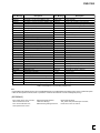
Table 7.1 Description of VR playback-related errors
[REFERENCE]
STC=System Time Clock ,
VOBU=Video Object Unit ,
GOP=Group Of Picture ,
B-picture= Bidirectionally predictive-picture
I-picture=Intra-picture,
P-picture=Predictive-pictute,
TP mode change=AV1 term (Trick Play mode change)
15
DVR-7000
Error Message
Description
Error Message
Description
Non Err
Normal
No Video
No video input (not locked)
DRAM NG
Abnormality in access to the DRAM for work
Invalid Param
Invalid parameter
SRAM NG
Abnormality in access to the backup SRAM for work Protect Src
Source to be recorded is write-protected.
CPRM IC NG
Inappropriate CPRM IC
Now Busy
In the process of the emergency processing
Drive Destroy
The drive was destroyed.
Invalid Disc
The disc cannot be recognized.
MKB REVOKED
Error in gaining data
Invalid UDF
Invalid UDF content
BK BATT Down
Backup RAM data has been erased.
Invalid VMG
Invalid VMG content
BK FSYS Dirty
Backup RAM data has not been written on the file system. Invalid TMVMG
Invalid TMP_VMGI content
Stream NG
Inappropriate input stream data
Unmatch Stamp
Impossible to modify because of unmatched time stamps
Stm Start NG
Failure to start encoding (reasons not clear)
Virgin DISC
Blank disc
Excel Hang
Dvexcel NG was announced.
Fail Repair
Repair failed.
No SysHdr IN
System packet is not input periodically.
ReadOnly DISC
Because part of data is invalid, data cannot be written.
Strm Start NG
Timeout of system packet input at the beginning
Rzn Rsv NG
R Zone Reserve failed.
IN Encode
Changes cannot be made in the process of encoding. Rzn Cls NG
R Zone Close failed.
EncModul Hang
Encoder routine is hung up.
R Zone Repair failed.
Rzn Rpr NG
Ourob Strm NG
Inappropriate stream data to the Ouroboros input
Bdr Opn
Open Border failed.
BUF Overflow
Overflow of stream buffer
Bdr Cls
Close Border failed.
Drive Hang
Drive is hung up.
Format NG
Formatting failed.
Write Err
The drive failed to write and could not be recovered. OPC NG
OPC failed.
Read Err
Reading failed, ECC failed, etc.
PCA Full
PCA has been used up.
Drv Hard Err
Abnormality in the drive hardware or firmware
RMA Full
RMA has been used up.
Mech No Res
No response from the mechanical U-Com
SW Vrec mode
Switching to video recording routine is required.
Drv TimeOut
Timeout for drive operation
SW Vpb mode
Switching to video playback routine is required.
NWA Exhaust
NWA surpassed and impossible to be used
Something
Something is wrong.
MKB Invalid
MKB reading error
Status NG
Abnormality in change of statuses
Drv Err
General error of the drive
Irr Action
Incorrect action
DISC Full
No further data can be written because the disc is full. Abort
Cancellation
No More Info
No more space in the internal work management area I am Down
A request to turn off the power was placed.
No Perm
No permission to write to the disc
Repair Exec
Repairing has been executed.
Limit Over
Standard maximum limit was over.
Format Exec
Formatting has been executed.
Rec Pause
No operation permitted during recording pause
BUG
Some bugs
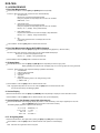
Table 7.2 Description of VR recording-related errors
Note :
* A dark halftone dot meshing part is an error of the MPEG Encoder, and a light halftone dot meshing part is an error of the drive system.
* When the drive system is errored, there is a problem in crack and dirt of the disc or drive oneself (pickup is dirty).
[REFERENCE]
ECC=4 Byte code for error correction ,
UDF=Universal Disc Format ,
PCA= Power Calibration Area ,
OPC=Optical Power Control
NWA=Next Writable Address ,
VMG=Video Manager ,
RMA=Recording Management Area ,
MKB= Media Key Block ,
TMP_VMGI=Temp Video Manager Information,
Border=from Lead-in to Lead-out ,
16
DVR-7000
3.1.4 SERVICE MODE
1. Error Rate Measurement
How to Enter this Mode : Press the [ESC] and [SIDE-B] buttons sequentially.
Functions : When enter this mode, measure the error rate automatically.
1 VR mode record
Record it for 10 seconds and playback the title.
During the playback and stop, display the error rate in FL and OSD.
ERR RATE : *.**E-*
2
Video mode record
Record it for 30 seconds and playback the title.
During the playback and stop, display the error rate in FL and OSD.
ER (av):*.*E-* * (Display - during measurements)
3
DVD-VIDEO playback
Playback, and measure the error rate and display it. Stop afterwards.
ER (av):*.*e-* * (Display - during measurements)
4
CD
Trace it from the lead of track 1 and display the error rate.
E. RATE:*.*e-*
How to Release : Press the [ESC] button to release from this mode.
2. Error Rate Measurement During DVD-VIDEO Playback
How to Enter this Mode : Press the [ESC] and [n] buttons sequentially during playback. (n: Numeric button)
Functions : When enter this mode, measure the error rate of DVD-VIDEO and display it.
Record it for 10 seconds and playback the title.
ER (av):*.*e-* * (Display - during measurements)
How to Release: Press the [ESC] button to release from this mode.
3. VR Aging Mode
How to Enter this Mode : Press the [ESC] and [REP.B] buttons sequentially to enter the aging mode.
Display [AGING] on the left part of FL and display loop count on the right part of FL during this mode.
Functions : When enter this mode, repeat the following operations automatically.
1 VR initialization
2 Video recording 60 minutes
3 Playback 45 minutes
4 Tray open
5 Tray close
Display the following counts in FL during the aging mode.
[ AGING 0001 ]
How to Release : Press the [ESC] button to release from this mode.
Note : Aging Mode stops when an error occurs. Press the [ESC] button to release from this mode.
And see the error history with Debugging Mode.
4. Version Display
How to Enter this Mode : Press the [ESC] and [FRM/TIM] buttons sequentially to display the version information screen.
How to Release : Press the [ESC] button to release from this mode. (screen disappears)
5. Version Display (for Remote Control Unit of Accessory)
How to Enter this Mode : Perform highlight display the position of “main unit setting / voice output / digital output / ON”, and
press the [ANGLE] button of the remote control unit of accessory.
The following display appears at a position of the third layer.
SYSCON
TUFLCON
DRIVE
DEVICE
:
:
:
:
RELEASE_1 1 2
1.5200
*
1. 6 1 C
*
AV1=ES6 . 0
6. FL All Lighting Mode
How to Enter this Mode : All FL lights when pressing the [ESC] and [TEST] buttons sequentially.
How to Release : Press the [ESC] button to release from this mode. (Return to normal display.)
Note : Take care not to light all FL Tube for long time.
17
DVR-7000
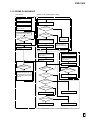
3.1.5 POWER ON SEQUENCE
Tuner U-com
System U-com (Inital Program Loader)
Connect a power cord to an
AC outlet.
The Tuner microcomputer starts.
The system control computer starts.
Initialization of peripheral circuit
register, RAM, etc.
LSI check
NG
OK
Time display on the FL display
FLASH check
NG
OK
Power on?
No
Yes
The firmware stored in the flash
memory is developed in SD-RAM.
The power is on and resetting is
released.
Jumping to the developed firmware
“LSI NG” displayed
in the FL display
Downloading via the RS232C
required. “FLASH NG” is
displayed in the FL display.
“POWER ON” displayed on the
FL display
System U-com
( Firmware )
DVD-R/RW Drive
The drive microcomputer starts.
Initialization of the peripheral circuit
register, RAM, etc.
Initialization of the peripheral circuit
register, RAM, etc.
Starting communication with the
tuner u-com
Disc detection
NG
Waiting for communication
to be established
OK
Waiting for data from
the drive
NG
Information on key inputs and channels
is transmitted to the system u-com; and
according to the instruction of the system
u-com, the FL display and the channels
are changed.
Has a command arrived?
No
OK
Yes
Is a disc in?
No
ATA/ATAPI command process
Yes
Is the disc valid?
No
Yes
Is repair required?
No
Yes
Tray open
Repair process
Is playback requested?
No
Yes
Play
Stop
18
DVR-7000
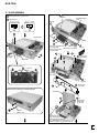
3.1.6 DISASSEMBLY
1
2
8
Remove the bonnet. (Screw ×10)
× 2 Disconnect the connector
CN2009
POWER SUPPLY
Assy
Open the tray.
Unhook
OPEN/CLOSE
STANDBY/ON
7
5
Barrier Sheet
6
5
CN204
7
9
7
Unhook the bottom side
4 marking parts.
Remove the front panel.
*Disconnect the FFC
and PH cable.
4
11
5
Remove the
tray panel.
11
×3
Unhook
×3
12
13
14
Tray Panel
Remove the
barrier sheet.
Rear side of the tray
3
× 4 Unhook
CN9001
(DV cable)
MAIN UNIT
12
×2
Unhook
10
10
×6
Remove the
front shield.
When opening the tray by manual operation
MAIN UNIT
15
×2
Stand up the
MAIN UNIT
to the hook.
2
1
16
Clip ,etc
(about 1.0φ)
Note:
MAIN ASSY operates
even if removing the DV
cable. Possible to diagnose
the TUNER ASSY,etc.(The signal of
the DV connection cannot be checked.)
19
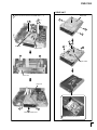
DVR-7000
DRIVE UNIT
16 Disconnect all connectors on the MAIN ASSY. ( ×7)
17
19
×2
Shield Case
2
1
19
20
1
1
18
3
4
4
Fan Duct
Upper Frame
21
×2
4
5
21
Clamper Holder
Drive Unit
Drive Unit
22
22
23
Remove the Drive Unit.
6
Make clean the pick-up lens.
20
DVR-7000
CAUTION FOR CABLE STYLING
Bariier Sheet
Do not sandwitch the DV cable
with the bonnet.
• Be sure to bind the cable from the POWER
SUPPLY ASSY with the wire saddle.
• Attach the barrier sheet.
Bind the cable with the binder.
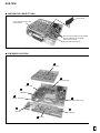
PCB BOARD LOCATION
E
MAIN Assy
B
REAR JACK Assy
C
3DY/C Assy
A
TUNER Assy
D
I
FRONT JACK Assy
POWER SUPPLY Assy
H
G
SW Assy
JOG Assy
F
FL Assy
21
DVR-7000
3.2 OUTLINE OF THE PRODUCT
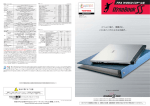
3.2.1 DVD-RW Standard
The DVD-RW disc is a phase-change type, rewritable disc, as are
CD-RW and DVD-RAM discs. In playback of a phase-change type
disc, signals that are obtained through the change in reflectivity
between crystalline and amorphous states of the recording layer can
be read by the optical system employed in playback-only players.
Fig. 1 shows the structure of a DVD-RW disc. On a 0.6-mm-thick
polycarbonate molded substrate, an Ag-In-Sb-Te-alloy recording
layer, a protective layer, and a reflective layer are deposited.
DVD-RW uses CLV-type groove-recording format, and employs
the wobble groove & land pre-pit system, as does DVD-R, for
rotation control and address information during recording.
For this, so-called LPPs (Land Pre-Pits) are provided on certain
locations in the land areas, and the groove has a minutely undulating
structure called "wobble." The wobble is mainly used for rotation
control of the disc, and the frequency of the wobble signal is 8 times
that of the sync frame (8 cycles in one sync frame). LPPs are located
from the first to the third bits of the sync frame at the maximum
oscillation of the wobble, and these three bits and one ECC (error
correction code) comprise preaddress information.
Table 1 shows the basic specifications of DVD-RW. The
specifications, such as the form of the disc, 4.7 GB/side recording
capacity, 0.4 µm minimum pit length, 0.74 µm track pitch,
modulation method, and error-correcting code, are the same as those
of DVD-ROM. The recording and playback wavelengths are both
635/650 nm.
As to the characteristics after recording, the reflectivity is within
the standard value of a dual-type DVD-ROM, and the specifications
for modulation and jitter are the same as those of DVD-ROM format.
Moreover, as the tracking system during playback, phase-difference
tracking is employed, analogous to DVD-ROM.
Table 1 Basic Specifications of DVD-RW
Diameter
Specifications
of DVD-RW
Phase Change
Re -writable
120/80mm
Pre-format
Spindle Control
User Data Capacity
Wobble & LPP
CLV
4.7G/1.46Gbytes
I t em
MediaType
←
-------←
Recording Rate
11.08M bps
8.54Gbytes * *
←
Record Wave Length
Playback Wave Length
6 35/650nm
635/650nm
-------←
Write Power
– 15 mW
--------
Track Pitch
0.74 µm
←
Minimum Pit Length
Data Modulation
Reflectivity
Case or Cartridge
Laser Beam
Specifications
of DVD-ROM
Read On ly
0. 4 µm
8-16 Modulation
←
18 – 30 %
45-85%*
18-30%**
--------
O ption
←
* Single Layer Disc
Land Pre-Pit
** Du al Layer Disc
Wobble
Polycarbonate
0.74µm
Groove
Land
Protective layer (ZnS-SiO2)
Recording layer (Ag-In-Sb-Te)
Protective layer (ZnS-SiO2)
Reflective layer(AL alloy)
2P Resin
Polycarbonate
Fig. 1 Structure of DVD-RW disc
22
DVR-7000
3.2.2 Video Recording Format
The DVD Forum created the DVD-Video format as an application
format. As this format was created mainly for the authoring systems
for a PC environment and intended to reduce the burden on playbackonly players, its data structure is not suitable for real-time recording.
As the DVD-Video format was for ROM discs, which do not require
addition of descriptions or edition by users, its fairly complex
structure posed little trouble for authoring systems. Therefore, the
format contained various items that allowed content producers to
use various functions, such as multiangle, multistory, various menus,
multilanguage, commands, and high picture/sound quality.
In comparison, in considering the use for general users' recording/
playback use, such as VCR, Camcorder, and MD, the Video
Recording format was defined to respond to the following requests:
1. Real-time recording
2. Easy to edit/operate
3. High picture quality
4. Efficient usage of available area on a disc
Table 2 shows the outline of Video Recording format data.
Table 2 General Specifications of Presentation Data
Data Systems
Video
Audio
MPEG-2 system stream / program stream
Maximum program_mux_rate = 10.08Mbps
compression
bit rate
MPEG-2
MPEG-1
:1
: Complies with MPEG-2 or MPEG-1
: 9.80 Mbps or less
: 1.856 Mbps or less
number of streams
: 2 max
coding mode
: Linear PCM / Dolby AC-3 / MPEG
number of stream
sampling frequency
bits per sample
bit rate (max.)
number of channels
Sub-picture
Linear PCM
Dolby AC-3
MPEG-1
MPEG-2
48kHz
16bits
48kHz
compressed
48kHz
compressed
48kHz
compressed
1.536Mbps
2 max.
448 kbps
5.1 max.
384kbps
2 max.
912kbps
7.1 max.
number of streams
: 1 max.
data type
data size of a picture
: Run-length coded bitmap , 2-bit/pixel
: 52KB max.
display area
: a rectangular in a frame
TV system with 525 / 60
: 720(H) × 478(V) max.
TV system with 625 / 50
: 720(H) × 537(V) max.
colors
: 16 colors palette for each VOB
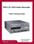
Fig. 2 shows a recorded content model. The original represents an
image of a group of titles previously recorded on a VCR and now
actually recorded on a disc. Up to 99 titles can be recorded on a
disc. A title may be actually recorded on noncontinuous areas, but
for users, it appears to be recorded continuously.
The play list is a program created from time information of actual
original titles, and a virtual title is composed only of management
information.
Any portions of titles can be selected in any order with accuracy to
one video frame in a play list. Up to 99 play lists can be created.
Both original titles and play lists can contain chapters.
Chapter
Original
Title 1
Title 2
Title 3
Title 4
Play list 1
Fig. 2 Recorded content model
23
DVR-7000
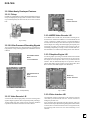
3.2.3 Main Newly Developed Features
3.2.3.1 Pickup
In addition to DVD-R/RW recording and DVD-ROM playback, the
newly developed pickup can play back CD media. The laser diodes
are provided separately for DVD and CD, but one lens is used for
both.
MAIN Assy
IC8008 PD0272A
Fig. 5 George
3.2.3.4 MPEG Video Encoder LSI
Fig. 3 Pickup
3.2.3.2 LSI for Process of Recording Signals
The conventional structure of 3 chips and a discrete circuit has been
integrated into 2 chips, realizing performance stabilization and cost
reduction.
RECORDER DRIVE
MAIN
IC109 PM0025AF
A new MPEG video encoder LSI, which enables recording in 3/4D1 and 2/3-D1 resolutions in addition to conventional full-D1 and
1/2-D1 resolutions available with the conventional MPEG-2
encoders, has been developed. This offers more options of resolutions
suited to length of recording, and enables higher picture quality even
with longer recording. It also reduces load on the host CPU by
substituting multiplexed processing of video and audio data for it,
and contributes to cost reduction by assuming the DV codec function.
3.2.3.5 Graphics Engine LSI
An LSI for graphics processing, such as full-resolution GUI and the
reduced-size-moving-picture-capture function, has been newly
developed for easier operation and an easy-to-understand user
interface. This can dramatically improve UI expression. This LSI
also has high-quality picture features, such as frame TBC (Time
Base Corrector) and 3DNR (Digital Noise Reduction).
RECORDER DRIVE
MAIN
IC602 PE5131A
Fig. 4 A2-Chip R3-Chip
MAIN Assy
IC4006 PD6342A
Fig. 4 Vaikilt
3.2.3.6 Drive Interface LSI
3.2.3.3 Video Decoder LSI
A video decoder LSI for high-quality conversion of analog video
signals to digital signals has been newly developed. By mounting a
10-bit/27-MHz video ADC, higher accuracy and better stabilized
reproduction of luminance and color have been realized.
Conventionally, SCSI was employed as a drive interface, and was
controlled by a dedicated LSI and CPU. Transfer of data was
managed by the host CPU.
Now, ATAPI has been employed as the drive interface, and a new
LSI has been developed. By transferring management of data transfer
to the LSI, drive-control functions have been converged to the LSI,
thus reducing load on the host CPU and contributing to cost
reduction.
24
DVR-7000
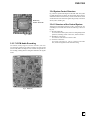
3.2.4 System Control Structure
MAIN Assy
IC3003 PE5219A
Fig. 9 shows a system block diagram of the DVR-7000. The system
is roughly divided into two blocks: the writer block (which writes in
and reads out data to and from a disc), and the recorder block (which
encodes/decodes video and audio signals and generally controls the
whole system, including UI).
3.2.4.1 Structure of the Control System
Fig. 7 Slalom
3.2.3.7 LPCM Audio Recording
Although the DVR-2000 contained 6 CPUs, including the one
controlling DV, the DVR-7000 contains the following 3 CPUs (see
Fig. 10):
(1) Recorder Main CPU
For control of the whole system, such as recording and playback
operations, including control of each CPU, and user interface
(2) Read/Write Control CPU
For control of read out/write in from/to a disc.
(3) Tuner/FL Control CPU
For control of the tuner, FL, 3-D Y/C, and keys of the main
unit, and for management of time and timer setting
The DDCE (Dolby Digital Consumer Encoder) has been
conventionally employed for audio encoding, and now LPCM
(Linear PCM) audio recording has been created as an algorithm for
AV encoding, enabling audio recording more faithful to the original
sound.
Fig. 8 MAIN Assy
25
DVR-7000
FLASH
H.A.
MPEG
Video Enc.
&
DVcodec
DDCD
Audery
DVxcel
Audio I/F
aprilia
(1/2)
DVD-ROM
Enc.
LD
Drv.
A2-Chip
SRAM
Main
CPU
FLASH
PU&Mecha
SDRAM
1394 Link
ceLynx
1394Phy
SRC
Audio
A/D
VIP
George
R3-chip
ATA-IF
DMA
I/F
Slalom
Ouroboros
CPU
Graphics
Engine
Tuner/FL
Control CPU
DVD-ROM Dec.
& D-Servo
M63
Vaikilt
Writer
VQE-3
VQE-5
DVD-ROM
Dec.
By-Chip
AV
Decoder
AV-1Chip
Audio I/F
aprilia
(2/2)
3D
Y/C
BS/UV
Tuner
/Line
in
Audio
D/A
FL
Y/C/Comp Video Out
Y/Cb/Cr Video Out
Audio Analog Out
DIF Out (Coax, Opt)
Recorder
Fig. 9 System block diagram
Tuner, FL, 3D Y/C and
main unit key controls,
Time management and
Timer reserved management
TU/FL
CPU
Serial communication
Main CPU
SH-3
IC1010
System control of
Writer UNIT
(DVR-103-PA)
Register access type
communication
Writer
CPU
SH-2
ATAPI BUS
ATAPI I/F
Slalom
IC3003
Control system wide such as
record / playback operation
including the control of each
CPU and user I/F, etc.
Conversion to ATAPI signal
Communication with
ATAPI command
Fig. 10 CPU control share
26
DVR-7000
3.2.4.2 Recording System
The basic flow of data with the DVR-7000 is similar to that with the
DVR-2000. Recordable media are DVD-R (Ver. 2.0) and DVDRW (Ver. 1.0/1.1), and recording application formats are Video
Recording Format (DVD-VR) and Video Mode Recording Format.
Only Video Mode Recording is possible with DVD-R discs, and
DVD-VR recording is possible with DVD-RW discs (Video Mode
Recording is also possible with Ver. 1.1 DVD-RW discs). The
available recording speed to discs is normal speed.
In DVD-VR recording, analog video and audio line input signals or
analog video and audio signals detected by the tuner are ADconverted, input to the Graphics Engine LSI, processed with the
frame TBC and 3DNR, then encoded and multimplexed in real time.
In the video and audio encoding block, based on the set recording
length or recording bit rate, the most suitable encoding parameter is
determined, and MPEG video encoding is made by variable bit rate
(VBR). Compressed video stream and audio stream compressed by
DDCE (Dolby Digital Consumer Encoder) are then packed and
multiplexed, and are formed into a basic VOB (video object)
conforming to the Video Recording Format. In the video stream,
necessary information stipulated in the Video Recording Format,
such as RDI (Real-time Data Information) in a VOB, is described.
Everything up to this process is done by the MPEG Encoder LSI. A
stream sent from this MPEG Encoder LSI is temporarily stored in
the SDRAM (stream buffer) of the ATAPI interface LSI. The main
CPU controls transfer so that the downstream will not overflow,
and the temporarily stored stream is then transferred to the writer
block via the ATAPI bus. As actual recording to a disc is done
intermittently, a write command is issued when data reach certain
amount, and a mass of data are transferred simultaneously.
The data is formatted into the DVD physical format in the DVDROM encoder of the writer block, then actually recorded on a disc
with the most suitable emission power of the laser diode and the
strategy. On the disc, data are recorded intermittently in blocks, and
these data blocks are linked with no linking loss.
In actual operation, one title is created by one sequence of a user's
starting recording through stopping recording. If recording is paused,
a chapter will be created. If the disc is removed from the unit, the
management information (file system and VR_MANGR.IFO, etc.),
which is managed by the main CPU and which is necessary to play
back the recorded video and audio signals, will be recorded on the
disc. Editing can be made on the originals and play lists. For editing
of a play list, only management information is updated and rewritten,
and VOBs are not rewritten. Thus, nondestructive editing is possible.
3.2.5 Playback System
3.2.5.1 DVD Playback
The path for transferring AV decoder data in the DVR-7000 has
largely been modified from that of the DVR-2000.
The path of DVD-video playback is the same as that of conventional
DVD-video playback: The RF signal read out from a disc is converted
into NRZI (non return to zero inverse) signal after passing through
the preamplifier, then is sent to the recorder block; There, the DVD
physical format is decoded. Then in the AV decoder, the signal is
decoded into digital video and audio data. This is basically the same
path as that the DVD-video player uses to play back a DVD-video
disc. The playback speed is normal speed.
During playback of a DVD-VR, the data-transfer path from the writer
block is the same as that in recording (via the ATAPI bus).
The RF signal read out from a disc is processed up to DVD physical
formatting in the writer block, transferred via the ATAPI bus, and is
temporarily stored in the SDRAM (stream buffer) of the ATAPI
interface LSI. Then, the data are transferred to the AV decoder and
decoded to video and audio digital data. Thus, for DVD-VR, the
same path is used for recording and playback during data transfer
from the recorder to the writer blocks. The playback speed of DVDVR is double normal speed (only for DVD-VR).
The AV-decoded data pass through the same path regardless of the
applications used. The digital video signal enters the Graphics Engine
LSI, where the overlay process with the GUI & OSD takes place. If
a disc-navigation display is called by the user, video capture and
multiscreen display processes are executed for the designated frame
(random designation possible) of each title. Then, the digital video
signal is processed with 3DNR in the NTSC Encode LSI to be output
as an analog video signal.
As to the audio signal, audio digital data to be output as an analog
signal are decoded in the AV decoder, and audio digital data to be
output as a digital signal are DIF-modulated after being decoded in
the AV decoder, then either signal goes to the AUDIO interface
LSI, where the signal to be output as a digital signal undergoes a
switching process, and for the signal to be output as an analog signal,
data are gathered for the level meter and switching process is
executed. The signal is then output through the DAC.
3.2.5.2 CD/Video-CD Playback
Playback of CD media is newly added for the DVR-7000. The basic
data flow is similar to that of a DVD-video player. Playback speed
of CD media is 4 times normal speed in CAV.
As to CD-DA playback, the RF signal read out from a disc is EFMdemodulated in the writer block. Then the signal to be output as an
analog signal is sent to the recorder block as a 3-line serial signal of
IEC60958 format, and the signal to be output as a digital signal is
DIF-modulated in the writer block and then is sent to the recorder
block.
The signal to be output as an analog signal via the Audio interface
LSI enters the SRC, where the sampling rate is converted from 44.1
kHz to 48 kHz. Then, the signal enters the Audio interface LSI again,
and is finally output through the DAC. The signal to be output as a
digital signal also undergoes a switching process in the Audio
interface LSI, and then is output as DIF.
As to Video-CD playback, as with CD-DA playback, the RF signal
read out from a disc is EFM-demodulated in the writer block. Then
the CD-ROM data for Video-CD is then sent to the recorder block
as a 3-line serial signal of IEC60958 format, as with the signal to be
output as an analog signal. In the recorder block, the data are first
decoded then sent to the AV decoder, where the data are decoded
into video and audio digital data. Then, the data pass and are
processed in the same way as with DVD playback and are then
output.
27
DVR-7000
3.2.6 Newly Added Functions and
Specifications
The following functions and specifications are newly added to the
DVR-7000, compared with the DVR-2000.
3.2.6.1 CD/Video-CD Playback
As mentioned before, the newly developed pickup for DVD-R/RW
recording, responding to two wavelengths, makes it possible to play
back CD media. The basic functions are the same as those of DVDVideo players.
3.2.7 Other Features and Specifications
Other conventional features and specifications are as follows:
• 96-kHz/24-bit DAC
• 48-kHz/20-bit ADC
• 3-Dimensional Y/C-separation circuit
• Frame TBC
• Responding to the DV (iLink) input/output
• Built-in BS tuner
• Disc Navigator
• Disc timer
• Commercial skip
3.2.6.2 Progressive Output
For the video output stage, the same chip set as that for the DVS737 is employed, and the D2 terminal is mounted to respond to the
progressive output. Therefore, the same functions as with the DVS737, such as 2-3 pull-down progressive scan and movementadaptable-type interpolation processing functions, are provided, and
the 10-bit/54-MHz video DAC is included. It also has functions
such as component-frame DNR and quantum noise reduction.
3.2.6.3 Picture Creation
The Picture Creation function, which integrally controls LSIs for
video input and output and settings of various NRs and which realizes
the highest recording and playback picture quality by making picturequality settings to best suit the video content, is provided. The most
suitable picture-quality setting is possible with a simple operation.
3.2.6.4 Recording in 3/4-D1 and 2/3-D1
Resolution
As mentioned before, a newly developed MPEG video encoder LSI
enables recording in 3/4-D1 and 2/3-D1 resolutions in addition to
the conventional full-D1 and 1/2-D1 resolutions available with the
conventional MPEG-2 encoders. This offers more options of
resolutions suited for length of recording, and enables higher picture
quality even with longer recording.
3.2.6.5 LPCM Recording
In addition to the conventionally used DDCE, LPCM recording is
provided to the DVD-recorder. This enables audio recording more
faithful to the original sound. LPCM recording is possible only with
MN32 recording rate.
3.2.6.6 Full-resolution GUI
The newly developed Graphics Engine LSI with full-resolution GUI
functions dramatically improves the power of expression. In
combination with the reduced-size-moving-picture-capture function,
an easy-to-operate and high-quality User Interface has been realized.
3.2.6.7 Special Playback
To improve the operability and performance as an editing machine,
various special playback functions and performance are provided.
Besides frame-by-frame playback in forward and reverse, special
playback functions, such as 1/2-, 1/4-, 1/8-, and 1/16-time playback
in forward and reverse, and reverse playback at normal speed in full
resolution are possible.
28
DVR-7000
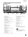
4. PANEL FACILITIES AND SPECIFICATIONS
4.1 PANEL FACILITIES
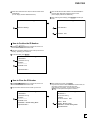
FRONT PANEL
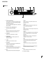
1
2
3
4
5
6
7
8
9
10
11
12
PureCinema Progressive
DVD RECORDER DVR-7000
SMART JOG
DVD
FL OFF
2DIGITAL
TIMER
Î
AUTO REC
STANDBY/ON
OPEN/CLOSE
FL DIMMER
0
DISCNAVI
OPEN
18
1
2
KU/CA type
STANDBY/ON button
FL DIMMER button
Press to change the display brightness
3
FL OFF indicator
Lights when the display is switched off using the
FL DIMMER button
4
DOLBY DIGITAL indicator
Lights when a Dolby Digital soundtrack is playing
5
DISCNAVI button
Press to display the Discnavi screen
16
15
14
REC
13
13 REC button/indicator
Press to start recording
14 8 PAUSE button
Press to pause playback or recording
15 3 PLAY button
Press to start or restart playback
16 7 STOP button
Press to stop playback or recording
OPEN/CLOSE 0 button
17 Disc tray
Press to open/close the disc tray
18 Front panel jacks
9
8 PAUSE
Turn to change the parameter selected with the
FUNCTION button
7
Lights when a DVD disc is loaded
3 PLAY
12 SMART JOG control
Display
DVD indictor
7 STOP
17
6
8
FUNCTION
Analog and digital input/output jacks for connecting a camcorder or other external equipment
TIMER indicator
Lights when the record timer is set and the power
is in standby
10 AUTO REC indicator
Lights when the recorder has been set for
automatic recording
This indicates a product feature that is
capable of playing DVD-RW discs recorded
with Video Recording format.
11 FUNCTION button
Press to switch the function of the SMART JOG
29
DVR-7000
DISPLAY
2
1
DVD CD VCD
VIDEO RW
R
RW
MN
TITLE
3
4
5
6
7
8
23
RESERVED
FINALIZE
LOCK PLAYLIST
TRACK CHP ANGLE
REMAIN
L
–∞
–40
–30
9
–20
–10
0
dB
R
SAP STEREO L R
CH
10
11
1
Play/record indicator
TITLE
Outer (white) ring indicates the playback speed
and direction. Inner (red) ring indicates elapsed
playback/recording time
Display shows the current title number of the
DVD disc playing
The center RW indicator lights when a VR mode
disc is loaded
2
DVD CD VCD VIDEO RW R
Shows the type of disc loaded
3
23
Shows the remote control mode (if nothing is
displayed, the remote control mode is 1)
4
FINALIZE
Lights when a finalized disc is loaded
5
RESERVED
Lights when a disc containing a disc timer
program is loaded
6
7
8
Display shows the current track number of the
CD or Video CD disc playing
CHP
Display shows the current chapter number of the
DVD disc playing
ANGLE
Lights when a multiangle scene on a DVD disc is
playing, indicating that you can switch angles
REMAIN
Display shows the amount of recording time
available on the disc loaded
SAP
Lights when the child lock is active
Lights when the currently selected TV channel
has a Secondary Audio Program channel
PLAYLIST
STEREO
Lights when a VR mode disc is loaded and the
recorder is in Playlist mode
Lights when the incoming TV signal is stereo
Audio level indicators
Indicates which channels are recorded/played
back when Dual Mono is selected.
LOCK
Monitors the ouput audio level during playback
and the input audio level during recording
9
TRACK
MN
Display shows the manual rate recording level
LR
10 CH
Channel indicator for the built-in TV tuner
11 Character display
30
DVR-7000
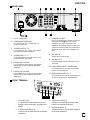
REAR PANEL
1
2
3
4
5
COMPONENT
VIDEO OUT
L
IN
PB
AUDIO
R
1
2
OUT
1
OUTPUT
2
/AUTO REC
INPUT
OPTICAL COAXIAL
DIGITAL OUT
11
AC IN – Power inlet
2
COMPONENT VIDEO OUT
7
S-VIDEO OUTPUT 1, 2
8
S-VIDEO INPUT 1, 2
9
CONTROL IN / OUT
VHF/UHF IN
VHF/UHF OUT
Passes the signal from the VHF/UHF IN to your
TV/monitor
DIGITAL OUT OPTICAL
For connecting to an AV receiver, Dolby Digital/
DTS decoder or other equipment with optical
digital inpu
6
9
Connect the TV antenna here
For recording from a camcorder, VCR or other
equipment with S-Video output
5
OUT
Use for connecting to other Pioneer components
bearing the Pioneer Î mark. Connect the
CONTROL OUT of one component to the
CONTROL IN of another using a mini-plug cord.
The device at the beginning of the chain acts as
the remote control sensor for everything in the
chain.
For connecting to a TV, monitor, AV receiver or
other equipment with S-Video input
4
IN
CONTROL
10
For connecting to a TV or monitor that has
component video input
3
8
VHF/UHF
VIDEO
PR
1
7
S-VIDEO
Y
AC IN
6
10 AUDIO/VIDEO INPUT 1, 2/AUTO REC
For recording from a camcorder, VCR, satellite
receiver or other equipment
DIGITAL OUT COAXIAL
For connecting to an AV receiver, Dolby Digital/
DTS decoder or other equipment with coaxial
digital input
11 AUDIO/VIDEO OUTPUT 1, 2
For connecting to the audio and video inputs of a
TV, monitor, AV receiver or other equipment
FRONT TERMINAL
DISC NAVI
DV IN/O
UT
1
S-VIDEO
VIDEO
L AUDIO
INPUT 3
R
2
1
DV IN/OUT jack
A combined input and output jack for connecting a digital camcorder. See page 19 for
details.
2
S-VIDEO input (INPUT 3)
Connect to an S-Video output of an external
component.
3
4
3
VIDEO input (INPUT 3)
Connect to a composite (standard) video
output of an external component.
4
AUDIO L/R (INPUT 3)
Connect to a stereo pair of audio outputs of
an external component.
31
DVR-7000
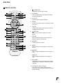
REMOTE CONTROL
1
STANDBY/ON
Switches the recorder on/into standby
1
2
STANDBY
OPEN
/ON
/CLOSE
CHP
NAVI
PLAYLIST MARK
SETUP
MARK
2
16
17
3
18
ERASE
19
EDIT
DISCNAVI
4
20
CHP MARK
Inserts a chapter marker when playing/recording a
VR mode DVD-RW disc
3
PLAYLIST
Switches beween Original and Playlist
4
5
ENTER
Shortcut to the erase function in the Discnavi or Title
List screen
21
5
6
7
8
PLAY
22
23
STOP
9
10
11
6
NEXT
¢
CHANNEL
25
REC
MODE
SEARCH
MODE
1
2
3
4
5
PlusCode
12
INPUT
SELECT
26
27
7
PROGRAM REPEAT
14
28
C
29
6
A-B
ANGLE
8
9
0
TV
INPUT SELECT
SHIFT
DISPLAY
15
8
L E
7
TV VOLUME
AUDIO SUBTITLE
TV CHANNEL
MENU
9
31
32
33
TOP MENU
34
Î
8 PAUSE
Pauses playback or recording
30
S
CM SKIP
Skips 30 seconds forward on the disc (about the
length of a typical TV commercial)
CLEAR
13
RETURN
Returns to the previously displayed on-screen
display
24
PREV
4
Jog dial
Controls scanning/slow motion speed and direction,
and frame advance/reverse
PAUSE CM SKIP RETURN JOG MODE
CM
8
REC
ERASE
¶ REC
Starts recording. Press repeatedly to set the recording time
10 4 PREV
Track or chapter skip/displays the previous page of a
menu
¢ NEXT
Track or chapter skip/displays the next page of a
menu
11 REC MODE
Switches the recording mode between SP to MN for
a VR mode disc, or between V1 and V2 for a Video
mode disc
12 PlusCode (G-code for LB type)
Press, then use the number buttons to enter a
PlusCode(G-code for LB type) programming number
for timer recording
32
DVR-7000
13 Number buttons
14 PROGRAM (Press SHIFT first to access)
Displays the program play screen
REPEAT (Press SHIFT first to access)
Selects the repeat play mode
A-B (Press SHIFT first to access)
Marks a loop for looped playback
25 CHANNEL –/+
Changes the channel of the built-in TV tuner
26 SEARCH MODE
Allows searching of the disc by title, chapter,
track, time, etc.
27 INPUT SELECT
Changes the input to use for recording
ANGLE (Press SHIFT first to access)
Switches camera angles on discs with multi-angle
scenes
28 CLEAR
SHIFT
29 –/––
Press first to access the above functions
15 TV controls
Use this remote to control your TV
16 0 OPEN/CLOSE
Opens/closes the disc tray
17 NAVI MARK
Selects a thumbnail picture for the current title for
use in the Discnavi screen
18 SETUP
Displays the Setup menu
19 DISCNAVI
Displays the Discnavi screen
20 EDIT
Shortcut to the editing functions within the
Discnavi or Title List screen
21 Joystick / ENTER
Clears the current setting, etc.
Press, then use the number button to enter a twodigit channel number
30 DISPLAY
Displays/changes the on-screen information
displays
31 AUDIO
Changes the audio language or channel
32 SUBTITLE
Displays/changes the subtitles included in
multilingual DVD-Video discs
33 MENU
Displays the disc menu of DVD-Video discs or the
Title List screen of Video mode DVD-R/RW discs
34 TOP MENU
Displays the disc ‘top’ menu of DVD-Video discs
or the Title List screen of Video mode DVD-R/RW
discs
Use the joystick to navigate all on-screen
displays. Press ENTER to select the currently
highlighted option.
22 JOG MODE button and indicator
Switches the Jog dial between scanning and
frame advance mode
23 3 PLAY
Starts playback
24 7 STOP
Stops playback/recording
33
DVR-7000
4.2 SPECIFICATIONS
General
Input/Output
System ................... DVD-Video, DVD-R/RW, Video-CD, CD
Power requirements ............... 120 V, 60 Hz(for KU/CA type)
Power requirements ...................... 110 V, 60 Hz(for LB type)
Power consumption ....................................................... 65 W
Power consumption in standby mode ............ 1.5 W (FL off)
Weight .......................................................................... 7.0 kg
Dimensions ..................... 420 (W) x 107 (H) x 373.5 (D) mm
Operating temperature .................................. +5°C to +35°C
Operating humidity ................. 5% to 85% (no condensation)
TV format ..................................................................... NTSC
VHF/UHF antanna input/output terminal ......... VHF/UHF set
75 Ω (F-shape connector)
Video input ...................................... Input 1,2 (rear), 3 (front)
Input level .................................................... 1 Vp-p (75 Ω)
Jacks ................................................................... RCA jack
Video output .......................................................... Output 1,2
Output level .................................................. 1 Vp-p (75 Ω)
Jacks ................................................................... RCA jack
S-Video input .................................. Input 1,2 (rear), 3 (front)
Y (luminance) - Input level .......................... 1 Vp-p (75 Ω)
C (color) - Input level ............................ 286 mVp-p (75 Ω)
Jacks ........................................................... 4 pin mini DIN
S-Video output ...................................................... Output 1,2
Y (luminance) - Output level ........................ 1 Vp-p (75 Ω)
C (color) - Output level ......................... 286 mVp-p (75 Ω)
Jacks ........................................................... 4 pin mini DIN
Component video output
Output level ........................................... Y: 1.0 Vp-p (75 Ω)
PB, PR: 0.7 Vp-p (75 Ω)
Jacks ................................................................. RCA jacks
Audio input ............................... Input 1,2 (rear), 3 (front) L/R
Input level
During audio input .................................................. 2V rms
(Input impedence: more than 22kΩ)
Jacks ................................................................. RCA jacks
Audio output ................................................... Output 1,2 L/R
During audio output ................................................ 2V rms
(Output impedence: less than 1.5kΩ)
Jacks ................................................................. RCA jacks
Control input/output ..................................... Mini jack 1 each
DV input/output ............... 4 pin (i.LINK/IEEE 1394 standard)
Recording
Recording format ................................ DVD VideoRecording
DVD-VIDEO
Recordable discs ................................... DVD-ReRecordable
DVD-Recordable
Video recording format
Sampling frequency ................................................. 13.5MHz
Compression format .................................................... MPEG
Audio recording format
Sampling frequency ..................................................... 48kHz
Compression format ................. Dolby Digital or Linear PCM
(uncompressed)
Recording time
DVD-RW (VR mode)
Standard (SP) .......................................... Approx. 2 hours
Manual rate (MN) ................................. Approx. 1–6 hours
DVD-R/RW (Video mode)
V1 ............................................................... Approx. 1 hour
V2 ............................................................. Approx. 2 hours
Tuner
Receivable channels
VHF ............................................................................ 1–13ch
UHF .......................................................................... 14–69ch
CATV ................................................................... C1–C125ch
Supplied accessories
Remote control .....................................................................
Dry cell batteries (AA/R6P) .................................................
Stereo audio cable (red/white) ............................................
Video cable (yellow) .............................................................
RF antenna cable ................................................................
Power cable .........................................................................
DVD-RW disc (KU/CA type only) .........................................
Operating Instructions (for KU/CA type) .............................
Operating Instructions (for LB type) ....................................
Warranty card (KU/CA type only) ........................................
Timer
Programs ............................................... 1 month/8 programs
Clock ............................ Quartz lock (12-hour digital display)
Power off memory ...................................... Approx. 48 hours
1
2
1
1
1
1
1
1
2
1
Note: The specifications and design of this
product are subject to change without notice, due
to improvement.
ACCESSORIES
Remote Control
(VXX2763 for KU/CA type)
(VXX2777 for LB type)
Stereo audio cable(L=1.5m)
(VDE1033)
Video cable(L=1.5m)
(VDE1034)
white
STANDBY
OPEN
/ON
/CLOSE
CHP
NAVI
SETUP
PLAYLIST MARK
MARK
ERASE
EDIT
DISCNAVI
yellow
ENTER
PAUSE CM SKIP RETURN JOG MODE
CM
8
REC
PLAY
PREV
4
NEXT
¢
PlusCode
REC
MODE
STOP
CHANNEL
SEARCH
MODE
INPUT
SELECT
CLEAR
1
2
4
5
PROGRAM REPEAT
3
red
C
6
A-B
Dry cell Batteries
(R6P,AA)
RF antenna cable(L=1.5m)
(VDE1025)
ANGLE
7
8
9
0
TV
INPUT SELECT
SHIFT
DISPLAY
S
TV VOLUME
AUDIO SUBTITLE
TV CHANNEL
MENU
TOP MENU
AC power cord
(ADG7021)
Î
34