1
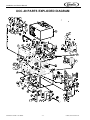
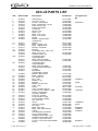
REMOTE COOLING UNIT
UC-40 and UCC-40
Installation and Service Manual
Release Date: September 28, 2004
Publication Number: 710160089
Revision Date: N/A
Revision: N/A
Visit the IMI Cornelius web site at www.cornelius.com for all your Literature needs.
INSTALLATION AND SERVICE MANUAL
The products, technical information, and instructions contained in this manual are subject
to change without notice. These instructions are not intended to cover all details or variations of the equipment, nor to provide for every possible contingency in the installation,
operation or maintenance of this equipment. This manual assumes that the person(s)
working on the equipment have been trained and are skilled in working with electrical,
plumbing, pneumatic, and mechanical equipment. It is assumed that appropriate safety
precautions are taken and that all local safety and construction requirements are being
met, in addition to the information contained in this manual.
To inquire about current revisions of this and other documentation or for assistance with
any Cornelius product contact:
www.cornelius.com
800-238-3600
Trademarks and copyrights:
Aurora, Cornelius, Decade, Hydro Boost, Sitco, Spirit, UF-1, Vanguard, Venture, Olympus, and Vista are registered trademarks of IMI Cornelius Inc.
Optifill trademark is pending.
This document contains proprietary information and it may not be
reproduced in any way without permission from Cornelius.
Printed in U.S.A.
Copyright © 2004, All Rights Reserved, IMI Cornelius, Inc.
Installation and Service Manual
IMPORTANT INFORMATION AND SAFETY NOTES. PLEASE READ BEFORE
INSTALLING DISPENSER.
•
Always transport equipment in an upright position and never drag over rough floors or down steps.
•
A trained person, who is qualified to make connections to water, electrical and/or compressed gas
supplies must only carry out installation and maintenance. Local by-laws/regulations must be
followed.
•
Switch off and unplug electrical power to unit during maintenance operations. Do not attempt to
remove any protective covers.
•
Locate equipment on a firm, level surface and protect from physical damage. Mounting surface must
be able to support 500 lbs. (227kg) weight. Never allow air vents/louvers to become blocked and do
not place any non-specified items on top. Regularly clean condensers and louvers with a soft brush or
vacuum.
•
This dispenser is for indoor use only. Do not expose equipment to extremes of temperature, water
spillage, spray, steam, or high humidity or clean with water jet into dispenser components because
this could cause damage to electrical components and shock to personnel. Do not place or store
objects on top of unit.
•
This dispenser must be connected to correctly rated electrical power outlet, preferably protected by a
safety cutout and is easily accessible for isolation of the equipment. The equipment must be earth
grounded.
• Use and ELCB (earth leakage circuit breaker)/GFCI (ground fault interrupt) for electrical power
protection.
• Use an HVAC circuit breaker to the power outlet circuit supplying the dispenser.
• Each module or accessory requires a 120 VAC 15 Amp 60 HZ grounded outlet. If 230 VAC 50/
60 HZ, use a minimum of 10 Amp outlet for each module or accessory.
•
Ambient temperature must not exceed 90 o F (32.3 o C) on units with merchandisers.
WATER SYSTEM
•
Insufficient water supply to carbonator will cause pump damage.
WARNING: If the installation is idle and exposed to freezing temperatures, disconnect water
supply lines and blow out all water from pump, carbonator tank, and dispensing system.
WARNING: UNDETECTED CO2 LEAKS MAY CAUSE HARM OR DEATH DUE TO ASPHYXIATION.
CO2 tank must be located next to a solid wall and chained to the wall. CO2 cylinders must be
secured in a vertical position and only connected to dispensing equipment via a suitable
pressure regulator. Check connections for leaks.
WARNING: DO NOT lift dispenser modules by valve housing assemblies. Lifting by the valve
housing assemblies will cause damage to the housing.
WARNING: System must be sanitized in accordance with the procedures found in this manual
under the cleaning and maintenance section.
WARNING: Before attempting to remove the refrigeration deck, disconnect all electrical power.
Melt the ice bank and thoroughly drain the water bath. See additional notes in Water Bath
Cleaning Section in the manual.
© 2004, IMI Cornelius Inc.
-1-
Publication Number: 710160089
Installation and Service Manual
SPECIFICATIONS
DIMENSIONS
See Illustration Below
SHIPPING WEIGHT
135 lbs. (61.4 kg)
OPERATING W EIGHT
241 lbs. (109.5 kg)
ELECTRICAL R ATING
115 VAC/60HZ/14.6 AMPS; 220VAC/50-60HZ/7.3 AMPS
Transformer: (Built In) 24VAC Secondary
REFRIGERATION
1/3 HP (Lift Out Type)
Condenser: Air Cooled
Refrigerant: R134a
APPROVAL
U.L., C.S.A., N.S.F.
Publication Number: 710160089
-2-
© 2004, IMI Cornelius Inc.
Installation and Service Manual
MECHANICAL SERVICE REQUIREMENTS
LOCATION
The dispenser will tolerate a surface +/- 1/2 o or +/- 1/8” per foot or +/- 10.4mm per meter maximum slope
without affecting refrigeration capacity or cause water spillage from water bath.
Do not install dispenser next to any heat producing equipment such as furnaces, ovens, deep-fat fryers.
Never store items on top of dispenser which will restrict the air flow through the air-cooled condenser coil.
Clearance: The space above the dispenser must have a minimum of 16 inches (406mm). Of clearance
to allow for the removal of the top cover and refrigeration chassis and to provide adequate ventilation.
There should be at least 1 inch (25.4mm) of clearance on each side and to the rear of the dispenser for
servicing and ventilation.
ELECTRICAL
The electrical power supply should conform with that printed on dispenser name plate.
All other electrical connections are to comply with local codes.
A wiring diagram can be found in Section 7.0 of this instruction manual.
A separate electrical circuit with a minimum rating equal to the electrical ratings shown on the dispenser
nameplate (amperage and voltage) is recommended for satisfactory operation.
WATER SUPPLY & D RAINAGE
A water supply having a 1/2” O.D. (12.7mm) copper water tube, minimum is required with a minimum 20
PSIG (1.4 bar) line pressure.
A shut-off valve within three feet (1 meter) of the unit is recommended.
A suitable water filter is recommended to ensure top quality drinks.
A water pressure regulator or reducing valve should be installed in line to the main water supply and set
at 30 to 40 psi (2.1 to 2.8 bar). By limiting the incoming water pressure, a 15 psi (1.05 bar) pressure
differential (water pressure versus higher carbonator CO2 gas pressure) will ensure that flooding of the
carbonator tank does not occur.
Teflon pipe tape should be used (as required) on any fittings used in the water system.
Any contaminants such as dirt, cutting oil, pipe dope left in the system may affect the quality of the
finished drink. Therefore, flush water lines prior to start up.
CARBON DIOXIDE (CO2) GAS SUPPLY
TO
CARBONATOR
For the product tank supply line use a CO2 regulator capable of 0 psig to 100 psig (6.8 bar) normal
working pressure. Recommended setting 75 psi (5.17 bar).
A minimum CO2 gas supply pressure 15 psi (1.05 bar) greater than the incoming water pressure will
ensure that flooding of the carbonator tank will not occur.
© 2004, IMI Cornelius Inc.
-3-
Publication Number: 710160089
Installation and Service Manual
SYRUP C OMPONENTS
Syrup containers, sold as an accessory, are stainless steel with a capacity of five gallons (18.9 liters).
They are equipped with a CO2 gas quick disconnect fitting and syrup quick disconnect fitting.
The dispenser’s syrup outlets are 1/4” (6.4mm) barb fittings, and are located at the front wall, mid-height,
of the dispenser.
Each syrup inlet in labeled with the valve number that it services.
If the “syrup in” lines need replacement or extension, a .265 I.D. (6.7 mm I.D.) polytube is recommended.
Avoid using soft or easily collapsible tubing on the “syrup in” lines.
Only stainless steel or plastic, barb or compression type fittings should be used on any syrup or soda
water connections.
Optional bag-in-box system is also suitable for use with this beverage cooler.
Publication Number: 710160089
-4-
© 2004, IMI Cornelius Inc.
Installation and Service Manual
INSTALLATION AND START UP PROCEDURE
1.
2.
3.
4.
5.
6.
7.
8.
9.
10.
11.
12.
13.
14.
15.
16.
17.
18.
19.
20.
21.
22.
23.
24.
Remove dispenser and related parts from the corrugated shipping carton.
Locate dispenser at point of operation.
Connect the building’s electrical supply to the dispenser’s main power box (see wiring diagram).
It is recommended that the unit’s drain be permanently plumbed to the building drain and conform
to all plumbing codes and regulations.
Remove the dispenser’s top cover by removing two screws found on the top surface of cover.
Remove the filler cap found on the refrigeration platform. Pour clean cool water through the filler
hole until water is seen flowing from the overflow tube which is connected to the building’s plumbing
system. Replace filler cap and top cover.
Now start the refrigeration system by plugging the system’s main power cord into the outlet
provided in the cabinet’s main electrical box.
It is normal to see a small amount of water being displaced from the water bath through the
overflow tube as the ice bank is built.
A generalized fluid/gas diagram is provided at the end of this manual.
Position the CO2 gas tank in a secure location. Assemble high pressure regulator to CO2 gas
cylinder and run jumper line to low pressure regulator.
Position the syrup tanks or bag-in-box components in the desired location. Attach the CO2 gas
lines leading from the low pressure regulator to these tanks, or B.I.B. manifold.
Connect syrup lines from tanks or bag-in-box system to the appropriate inlets at the front of the unit.
The syrup outlet lines from the cooling unit to the dispensing tower(s) are now connected using
(normally .265” I.D.) insulated polytubing conduit.
The low pressure gas regulator which controls the flow of syrup to each dispensing valve is
normally set at 25 psig to 35 psig (1.75 to 2.45 bar) or as required for proper operation of the valve.
For diet type syrup, the tank pressures should be set at from 3 to 8 psi (.21 to .56 bar) or as
recommended by the syrup supplier. Additional pressure may be necessary depending on the
distance from the syrup tank to the unit.
Mount the water filter assembly (if used) and water regulator in a convenient location.
Connect water inlet line to water regulator, set at 30 to 40 psig (2.1 to 2.8 bar), to water filter, and
then to the 3/8” (9.5mm) barbed water inlet of the UCC-40.
Connect a (.265” I.D.) (6.7mm I.D.) CO2 gas line from the high pressure CO2 regulator to the 1/4”
(6.4mm) barbed “CO2 Supply Connection” fitting at the UCC-40. This fitting supplies CO2 gas to
the built-in carbonator tank. The normal setting range of the high pressure CO2 gas regulator is 55
to 80 psi (3.85 to 5.6 bar), but may be set as high as 100 psi (7 bar).
The soda water outlet fitting of the UCC-40 (a pump with tag) is connected to the dispensing
tower(s) using the 3/8” I.D. (9.5mm I.D.) line of an insulated polytubing conduit.
The recirculating (return) soda water from the dispensing tower(s) is connected to the 3/8” (9.5mm)
barb fitting (tag) of the UCC-40 using a 3/8” I.D. (9.5mm) line of an insulated polytubing conduit.
After all connections to water, CO2 gas, electrical power and syrup containers are made, check for
leaks.
Be sure syrup tanks or BIB boxes contain syrup.
Turn on water. Open the pressure relief valve on the carbonator tank by lifting the wire ring, and
hold it open until water flows from the relief valve. Close the relief valve and turn on the CO2 gas
and electrical power in that order. DO NOT operate carbonator pump with water supply shut off.
To fill all lines with carbonated water, cycle the carbonator several times by operating the
dispensing valves. If valves do not operate check that the valve switch it “ON”.
The recirculating soda water “pump/motor” is controlled by the rocker switch at the unit’s electrical
box identified as “RECIRC. PUMP SWITCH”. This switch is now turned “ON”.
The dispensing valves should be adjusted in accordance to the instructions of the dispensing tower
or valve manufacturer.
© 2004, IMI Cornelius Inc.
-5-
Publication Number: 710160089
Installation and Service Manual
ICE BANK CONTROL REPLACEMENT
1.
2.
Disconnect power to dispenser.
Remove cap from drain tube and position the drain tube in the drain pan and drain the water bath.
3.
Refill water bath with warm water at a temperature of 120 o F (49 o C). Let stand for ten (10) minutes
to melt ice bank. If ice remains, repeat Steps 2 and 3 until all ice is melted. Failure to melt all ice
may cause the dispenser to freeze-up after the new ice bank control is installed.
Remove two screws from dispenser top and remove top.
Remove old ice bank control.
Install new ice bank control by pushing probe down into the 3/4” tube until it stops on the bottom of
the tube. Secure probe with tape.
Fill water bath with fresh water. Replace dispenser top and secure with two screws.
Connect dispenser to power source and turn ON.
4.
5.
6.
7.
8.
Publication Number: 710160089
-6-
© 2004, IMI Cornelius Inc.
Installation and Service Manual
CLEANING AND MAINTENANCE
NOTE: The dispenser must be cleaned and sanitized after installation and, thereafter, as required
by state and local health departments, or every three months minimum.
Continuous maintenance of this unit is a basic requirement for proper operation and sanitation, including
all support equipment utilized in the daily operation of this equipment.
1.
2.
3.
4.
On a daily basis, clean the external cabinet (splash areas) with mild soap and warm water. Wash
the cup rest and drip pan in cleaning solution and rinse with warm tap water. DO NOT use strong
bleach or detergents or they may discolor and corrode the cabinet materials. DO NOT use steel
wool or other abrasive scouring pads.
DO NOT use excessively hot water which may cause damage to plastic components.
The water bath should be cleaned two to four times annually, depending upon local water
conditions and in accordance with state and local health departments.
Cleaning of the refrigeration components should be performed by a qualified service person.
Disconnect power before removing the dispenser top. The dispenser top grilles should be cleaned
periodically to maintain efficient refrigeration. Condenser fins should be combed, if needed, to
maintain adequate circulation. Clogged condensers can lead to premature compressor failure.
SANITIZING, CLEANING, & MAINTENANCE
This section details the following:
A. Sanitizing of System
B. Daily Cleaning
C. Ice Water Bath Maintenance
It will be necessary to periodically check and correct the water level of the water bath.
The frequency of filling will depend on the environment within which the dispenser is operating and
consequently, the degree of evaporation of water.
Noisy operation and/or reduced cooling capacity can be caused by insufficient water in the water bath.
The condenser coil will require periodical cleaning to ensure correct air flow and cooling at the
condenser. The frequency of cleaning will depend on the environment within which the dispenser
operates.
All refrigeration components have been factory lubricated for life-time service and will require no further
lubrication.
CLEANING AND SANITIZING PROCEDURE
Water Circuits: Cleaning and sanitizing is not required for potable water circuits. Potable water lines
should remain connected and operational during the cleaning and sanitizing procedures for syrup
circuits.
NOTE: Carbonated Water Lines must remain connected and operational during cleaning and
sanitizing of the syrup circuits. Sanitizing of the valve without the carbonated water side
operational, may leave bacteria in the nozzle, diffuser, and syrup tube.
CLEANING E QUIPMENT AND S UPPLIES
•
Recommended cleaner: A.C. Fergusson Company #3391 or any caustic-base (low sudsing, nonperfumed, easily rinsed) detergent solution which provides a minimum 2% sodium hydroxide. The
solution should be prepared in accordance with the manufacturer’s instructions. Solution should be
room temperature.
•
Recommended sanitizer: A.C. Fergusson Company SuperChlor (1 ounce in 5 gallons of water) or
any sanitizer which provides a minimum of 200 parts per million of available chlorine. Solution should
be room temperature.
© 2004, IMI Cornelius Inc.
-7-
Publication Number: 710160089
Installation and Service Manual
•
Three five (5) gallon figals (syrup tanks) and fittings, cleaned and sanitized (one for water; one for
cleaner; one for sanitizer)
•
Containers for cleaner and sanitizer solutions
•
Clean, nonabrasive cloths
•
Bucket
•
Small brush
•
Extra nozzles
•
Extra jumpers
CLEANING PROCEDURES
1.
Disconnect each syrup container from its product line. Fill a figal with clean water, pressurize to 40
to 60 psig and connect the pressurized figal to the syrup product line. Remove syrup from the lines
by activating the dispensing valve. Continuously activate the dispensing valve until all syrup has
been purged from the product lines and valves as noted by the flow of clean water from the valves.
All product lines should be sequentially purged of syrup using this procedure.
2.
Clean all lines and fittings with cleaning solution and rinse with clean, room temperature water to
remove all traces of residual product.
3.
Clean each valve product line as follows: Fill a figal with dissolved cleaning solution, pressurize to
40 to 60 psig and connect the pressurized figal to the syrup product line. Activate the dispensing
valve continuously for one (1) minute to remove all air bubbles. Pressurize the lines by pulsing the
valves, 15 seconds ON, OFF, then immediately ON again for fifteen (15) cycles, then allow the
valve to remain flowing for three (3) minutes. Repeat pulsing and flowing the valves again until all
cleaning solution has been used.
WARNING: DO NOT allow cleaning and sanitizing solutions to remain in syrup systems longer
than is necessary to complete these procedures. Exceeding contact time will result in damage to
valve components.
4.
5.
6.
7.
8.
Wait three (3) minutes and then flush the cleaning solution from the lines with clean water by
connecting a pressurized figal with clean water. Pressurized and flush the valves by pulsing the
valve for (15) cycles and then flushing three (3) minutes as described in the previous paragraph.
Continue pulsing and flushing until testing with phenolphthalein shows the rinse water is free of
residual detergent.
Sanitize each valve product line as follows: Be sure all connections are cleaned and sanitized
before connecting to each product line. Fill a figal with dissolved sanitizing solution, pressurize to
40 to 60 psig and connect the pressurized figal to the syrup product line. Activate the dispensing
valve continuously for one (1) minute to remove all air bubbles. Allow the sanitizing solution to flow
through each valve while activating the valves for fifteen (15) cycles, then leave valves OFF and
allow to stand pressurized for thirty (30) minutes. Activate the valves for fifteen (15) cycles, then
flush remaining sanitizer continuously through the valves.
Remove the nozzles and the diffuser assemblies from the valves, disengage diffuser assembly
components and clean with cleaning solution. Agitate the assemblies to assure assemblies are
clean. Place them in a container of sanitizing solution for fifteen (15) minutes. Wearing sanitary
gloves, remove the nozzles and diffuser assemblies from the sanitizing solution, drain dry, then
reassemble them to the valves.
Reconnect the syrup containers to their respective circuits and ready the unit for operation.
Draw drinks to refill lines and flush the sanitizing solution from the dispenser. Taste the beverage to
verify that there is no off-taste (chlorine).
WATER B ATH C LEANING
It is recommended that the water bath be cleaned two to four times annually, depending upon local
conditions and/or required by state and local health departments. The water bath should be clean to
obtain maximum cooling efficiency.
Publication Number: 710160089
-8-
© 2004, IMI Cornelius Inc.
Installation and Service Manual
WARNING: Melt ice bank completely, disconnect electrical power and the wiring harness quick
disconnect on the refrigeration deck before draining the water bath and attempting to remove the
refrigeration deck from the water bath or permanent damage to the deck or coil basket may
result.
The water bath compartment is well insulated and it may take five or six hours for the ice to melt.
Refilling with warm water may help to melt the ice more rapidly.
1.
2.
3.
4.
5.
6.
7.
8.
9.
10.
Remove plug from the drain tube (located under the drip tray) and position the tube to drain into the
drain pan.
After the ice has melted, remove the deck.
Thoroughly clean around all the coils and between all crevasses with a brush and cleaning solution
to remove all algae and foreign matter. Dry the water bath.
Clean the condenser with a vacuum cleaner or a soft bristle brush.
Clean compressor, agitator motor and fan assembly with a cloth, wiping off accumulated dust.
Place the refrigeration deck into its original position.
Replace drain tube plug and fill the water bath with clean cold water.
Reconnect the wire harness on the refrigeration deck.
Place cabinet top back onto the unit in its original position and secure.
Clean and sanitize product lines and valves per number 4 above before placing dispenser into
service.
© 2004, IMI Cornelius Inc.
-9-
Publication Number: 710160089
Installation and Service Manual
LIQUID LEVEL CONTROL WITH TIMER
PURPOSE OF L.L.C.
WITH
TIMER
The liquid level control with timer is designed to protect the pump of a carbonation system against
running dry and consequent pump damage.
OPERATION
Designed to operate as a normal liquid level control under normal conditions. The timer circuit monitors
the running time of the pump motor. If the pump motor runs continuously for the specified time period,
the timer circuit will discontinue the operation of the pump motor until the reset switch is manually reset.
NOTE: The built-in carbonator normal refill time for the UCC-40 is 3 to 5 seconds (15 fl oz. [444
ml] normal refill volume).
Usually, when the water flow to the pump is interrupted for any extended period, the residual water
present in the pump warms up and will eventually evaporate, but as it warms up it continues to lubricate
the wear points of the pump. Experience has shown that a seven minute interruption in water flow is not
significantly detrimental to the future operation of the pump.
WARNING: The L.L.C. with timer will give no protection against the initial startup of a new
carbonator pump with no water being present at the pump. A new pump which has never
pumped water is considered dry and will suffer damage in a matter of 2 to 3 minutes.
FEATURES
220v/50z and 115v/60z models are available.
3-minute and 7-minute models are available.
Designed to control and protect a 1/2hp maximum pump motor.
Reset
A. Challenger and Enterprise carbonator.
• Separate manual reset switch (#35-0181) ensures that the cause of the problem has been
corrected before continued use of the pump motor. This feature has been provided in these
carbonators since January 1, 1995.
• Carbonators built before January 1, 1995 can be fitted with the time style liquid level control and
can be manually reset be disconnecting the power supply cord from the electrical supply and then
reconnecting same.
B. Overcounter Dispensers with built-in Carbonators (models CTC-20, CTC-40)
• These models have a rocker switch which controls the power supply to the liquid level control
(carbonation system). This switch is accessible through the top surface of the top cover of the
CTC-40, and located on the top left corner of the front valve mounting plate of the model CTC-20.
The timer can be reset by turning this rocker switch “off” and then “on” again.
Publication Number: 710160089
- 10 -
© 2004, IMI Cornelius Inc.
Installation and Service Manual
WIRING DIAGRAM
60439011 230V/50H Z
60439010 115V/60H Z
60439013 230V/50 Z
60439012 115V/60 Z
© 2004, IMI Cornelius Inc.
- 11 -
Publication Number: 710160089
Installation and Service Manual
FLUIDS/GAS DIAGRAM
Publication Number: 710160089
- 12 -
© 2004, IMI Cornelius Inc.
Installation and Service Manual
WIRING DIAGRAM
UCC-40 WIRING D IAGRAM
© 2004, IMI Cornelius Inc.
- 13 -
Publication Number: 710160089
Installation and Service Manual
UCC-40 PARTS EXPLODED DIAGRAM
Publication Number: 710160089
- 14 -
© 2004, IMI Cornelius Inc.
Installation and Service Manual
UCC-40 PARTS LIST
Item
New Part No
Description
Old Part No.
1
2
3
4
5
26-0064
26-0146
55-0339
23-0218
35-0128
35-0124
55-0087
23-0510
35-0015
35-0094
35-0097
23-0302
23-0040
Cabinet Ass’y
Coil Ass’y - Freon
Control - Temperature
Plate - Compressor (1/3 hp)
Power Cord (115v)
Power Cord (220v)
Condenser
Shroud - Fan
Blade - Fan
Motor - Fan (115v)
Motor - Fan (220v)
Handle
Bracket - Agitator Motor
(2 Required)
Washer
Motor - Agitator 115v
Motor - Agitator 220v
Bracket - Fan Motor
Bushing
Compressor Ass’y 1/3hp 115v
Relay 1/3 hp 115v
Overload 1/3hp 115v
Compressor Ass’y
1/3hp 220v/50hz
Relay 1/3hp 220v/50hz
Overload 1/3hp 220v/50hz
Compressor Ass’y
1/3hp 220v/60hz
Relay 1/3hp 220v/60hz
Overload 1/3hp 220v/60 hz
Lid Gray
Bulb Holder
(Temperature Control)
Bracket - Bulb Holder
Blade - Agitator
Pin - Cotter S.S.
Plug - Cap
Bracket - Line
Bushing
Basket - Product Coil
Tube - Vinyl
Clamp
Tube - Insulation 3/8 I.D.
Connector S.S. 3/8 MPT x 3/8B
Fitting - Compression
3/8 Tube x 3/8 MPT
Pump S.S. 50 GPH
Cover Insulation (Left)
Cover Insulation (Right)
Nut - Pack 3/8
Screw
Clamp V c/w Bolt
Pin - Hitch
Motor 1/3hp 115v
Motor 1/3hp 220v 50/60hz
O Ring
Coil Assembly CO2 Water
Cover - Electrical Box
Wrapper Electrical Box 115v
Wrapper Electrical Box 220v
Control - Liquid Level 115v
Control - Liquid Level 220v 50/60hz
Screw
119-178-007
119-184-001
155-969-000
119-066-004
119-360-000
115-558-000
101-434-000
115-194-000
105-240-000
119-646-000
119-805-220
119-118-000
115-659-000
6
7
8
9
10
11
12
13
16b
40-0411
35-0078
35-0079
23-0107
55-0031
26-0360
35-0148
35-0104
26-0366
16c
35-0151
35-0106
26-0362
17
18
35-0152
35-0107
23-0419
26-0061
19
20
21
22
23
24
25
26
27
28
29
23-0064
26-0058
40-0252
40-0262
23-0130
55-0033
23-0208
65-0085
40-0019
65-0047
40-0081
40-0243
14
15
16a
30
31
32
33
34
35
36
37
38
39
40
41
42
43
55-0275
55-0215
55-0214
40-0249
40-0297
35-0035
35-0115
35-0072
35-0075
40-0208
26-0136
23-0231
23-0819
23-0783
35-0062
35-0065
40-0288
© 2004, IMI Cornelius Inc.
- 15 -
Torrington Part
No.
186074001
106-141-000
119-447-009
119-447-229
103-024-000
103-067-000
101-049-000
101-050-000
119-803-001
119-803-002
119-803-261
119-803-262
119-165-007
112-544-675
119-791-097
115-790-001
106-140-000
113-035-000
119-185-707
119-426-875
119-192-001
104-299-000
108-111-000
104-249-000
115-576-000
119-688-002
107-776-000
115-396-000
115-395-000
119-689-000
110-861-902
100-361-000
101-046-002
115-442-000
115-442-220
103-123-000
119-993-728
119-446-001
119-465-006
119-465-001
110-863-000
110-863-220
103-462-000
31699012
34065
48114005
77081400
718400297
20543
60030058
71860673
31525012
60439010
Publication Number: 710160089
Installation and Service Manual
44
45
46
47
48
49
50
51
52
53
54
55
56
57
58
59
60
61
62
63
64
65
66
67
68
69
70
71
72
73
74
75
76
77
78
79
80
81
82
83
84
85
86
87
88
89
90
91
92
93
94
95
96
97
98
99
23-0230
55-0035
35-0137
40-0038
26-0888
35-0182
23-0185
40-0424
40-0282
40-0407
35-0055
35-0158
23-0303
40-0284
40-0294
40-0241
40-0240
40-0204
40-0244
26-0345
35-0035
40-0046
40-0418
40-0175
40-0153
26-0431
55-0276
26-0421
40-0116
40-0016
65-0003
40-0409
26-0038
40-0065
40-0412
40-0120
40-0418
23-0070
40-0422
40-0188
55-0073
40-0216
26-0685
55-0040
26-0037
55-0198
55-0197
40-0206
40-0130
40-0208
55-0013
55-0012
55-0011
40-0207
55-0010
55-0016
Publication Number: 710160089
Cover - Electrical Box (115 v only)
Bushing
Receptacle Single Outlet (115v only)
Fitting - Compression 3/8B x 3/8 Tube
CO2 Water Return
Switch - Rocker
Box Electrical (115v only)
Washer - Cup
Screw
Washer
Grommet
Sleeve
Heat Sink
Screw
Screw
Fitting Compression 1/4 Tube x 3/8 B
Fitting Compression
O Ring
Nut - Pack 1/4
Coil Pre-Chill
Clamp V c/w Bolt
Connector Brass 3/8MPT x 3/8 F
Washer 3/8 Flare
Nut - Swivel 3/8F
Nipple - Swivel 1/4B
Filter Assembly
Pump - Brass 125 GPH
Electrode Assembly 19”
Elbow S.S. 1/4B X 1/4 Swivel Nut
Clamp
Tube - Braid
Washer 1/4 Flare
Back Check Single
Connector S.S. 1/4B X 1/4B
Washer
Elbow S.S. 3/8B X 1/4 Swivel Nut
Washer 3/8 Flare
Bracket - Mounting Carb Tank
Washer - Lock S.S.
Nut S.S. 1/4
Carb Tank Ass’y
O Ring
Valve - Pressure Relief
Insert - Water Inlet .087
Back Check - Double Valve
Body - Filter Brass 3/8 NPT
Screen - Filter
O Ring
Fitting Inlet Brass 3/8 F
O Ring
Spring - Back Check
Ball - S.S. Back Check
Seat Fitting - Back Check
O Ring
Body - Single Back Check 1/4 Flare
Body - Double Back Check
- 16 -
119-070-002
119-446-000
119-425-000
119-688-000
119-993-729
115-650-000
119-070-006
119-435-001
119-435-001
103-296-000
101-162-001
119-622-000
105-139-000
102-649-000
108-120-000
119-334-000
119-078-000
103-074-000
105-313-000
119-865-002
100-361-000
115-109-375
115-354-000
110-918-000
110-919-000
110-934-000
110-872-000
119-915-019
112-708-000
105-039-000
115-115-000
104-053-000
113-139-000
100-826-000
110-861-004
115-512-000
115-534-000
119-891-006
119-903-000
119-464-001
119-862-007
113-180-000
110-948-000
110-862-087
110-947-000
110-924-00
103-948-000
103-113-000
110-924-000
103-123-000
115-050-000
115-049-000
115-048-000
103-122-000
115-046-000
115-449-000
60285002
60065064
77030402
20543
48033002
77030100
77040100
48114003
174478000
30359
65259001
77040200
77040900
4803002
40734001
71860230
31525012
64560
31525003
© 2004, IMI Cornelius Inc.
IMI Cornelius Inc.
www.cornelius.com


![Installation and Service Manual [ 000760 ]](http://vs1.manualzilla.com/store/data/006033913_1-538733b631fdf0b746407031ace8c980-150x150.png)