1
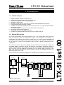
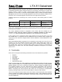
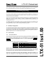
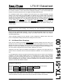
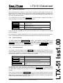
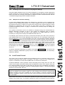
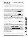
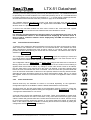
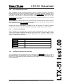
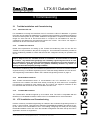
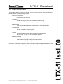
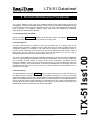
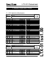
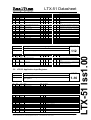
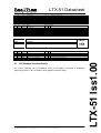
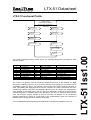
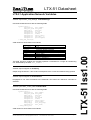
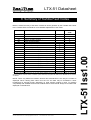
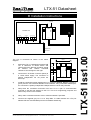
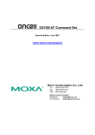
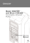
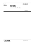
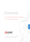
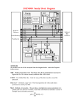
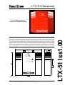
LTX-51 Datasheet LTX-51 BMS Gateway for Toshiba air-conditioning units The LTX-51 is a Modbus BMS interface for integrating R22 and R407C Toshiba RAV range air-conditioning units with BMS systems such as Cylon. The gateway removes the need for hardwired connections to BMS input and outputs and replaces them with a networked connection. All functionality available using hardwired inputs is available, in addition specific fault-codes from the Toshiba system are reported as BMS alarms and can be received by any connected BMS supervisor either on site or remotely. Furthermore the return-air and heat-exchanger temperatures from each unit are also fed back for control and monitoring purposes. The gateway can handle up to 16 independent zones, removing the need for up to 80 hardwired i/o points on the BMS, and can report fault codes from each of the indoor units connected. 144.00 37.00 Power LED LTX Service Pin SERVICE Service LED 134.00 Dimensions (mm) RealTime Control Systems Ltd. Park House, Greenhill Crescent, Watford WD1 8QU. Tel 01923 233384 Fax 01923 233385 Web: www.realtime-controls.co.uk, E-mail: [email protected] LTX51 Datasheet Issue 1.00.00 27/03/202 Page 1 LTX-51 Iss1.00 Description LTX-51 Datasheet 1 Introduction 1.1 LTX-51 Features Modbus standard interface via RS-232 port Independent control of up to 16 air-conditioning units Software configurable Master/Slave groupings No BMS I/O points used Reporting of fault codes for each of the 16 indoor units and attached outdoor units. Programmable default operating conditions Feedback of measured temperatures from each indoor unit – no need for separate space temperature sensors Co-ordinated BMS and local user control with keypad lockout facilities Remote unit reset and fault clearance. Compatible with other LTX-Modbus products Extendible to multiple Modbus devices using only a single serial port. 1.2 System Description The LTX-51 allows BMS control and monitoring of up to 16 Toshiba RAV units without the need for hardwired points. As illustrated in Figure 1 this integration is achieved by a combination of a RealTime LTX-51 and a Toshiba LG1. The LTX-51 is also compatible with the RealTime LRC-LG interface, and a single LTX interface can be configured to interface to an LG1 and one or more LRC-LG interfaces to allow control of different combinations of airconditioners. The LTX-51 provides an RTU mode Modbus RS-232 connection for interfacing to BMS with compatible Modbus interfaces. Consult the RealTime LTX-Modbus Engineering Guide for specific interfacing details. This guide also covers the use of multiple LTX products through a single interface to provide additional functionality such as LonWorks SNVT interfacing to the BMS. This datasheet describes the LTX-51 version 1.00. This is compatible with the LTXModbus firmware version 1.00. The control of the air-conditioning equipment is achieved via the Toshiba LG1 interface, one of LonWorks Network RealTime LTX-21 Network Power Toshiba LG1 TOSHIBA AIR CONDITIONING LTX-20 X-Y Network RS-232 Upto 16 units in total RBC - LG1 - PE LonWorks 1:16 GATEWAY RS-232 Connection Indoor Unit Indoor Unit Indoor Unit Indoor Unit Software Master/Slave Group BMS Outstation Remote Controller Figure 1. LTX-51 Topology RealTime Control Systems Ltd. Park House, Greenhill Crescent, Watford WD1 8QU. Tel 01923 233384 Fax 01923 233385 Web: www.realtime-controls.co.uk, E-mail: [email protected] LTX51 Datasheet Issue 1.00.00 27/03/202 Page 2 LTX-51 Iss1.00 LTX-51 Datasheet which is required for every 16 indoor units. Both the LTX-51 and Toshiba LG1 are based on LonWorks® technology which allows the devices to be directly connected via a single freetopology network. In order to enable communications between the LTX-51 and the LG1 interfaces it is necessary to ‘bind’ the devices together using a suitable LonWorks Network Management tool. An LTX-51 is normally required for each LG1 in the system, multiple LTX-51 interfaces can be networked together and accessed via a single RS-232 interface. Interfaces required for connecting to the LTX-51 are shown in the following table of Toshiba products. RAS - xxx R22 – Series 0 to 3 R407C – Series 4 à à RAV - Heatpump RAV – Cooling only LRC-LG LRC-LG Toshiba LG1 LG1/LRC-LG* *NOTE: Series 4 Cooling-Only split units do not have X-Y connections and are therefore not compatible with the LG1. However ‘Cooling-only’ units in VRF applications are actually ‘heat-pump’ indoor boards (with the –H) in the unit code, these are compatible with the LG1 as they have X-Y terminals. Larger systems can be controlled by either using multiple LTX-51 and LG1 pairs, or by using the Toshiba WG1 in conjunction with the RealTime LTX-52 interface which supports the control of up to 64 units from a single interface. See the RealTime LTX-52 datasheet for more information. With Toshiba Modular Multi a separate LG1 is required for each outdoor unit. The LTX-51 can manage up to two LG1 interfaces (and hence two modular multi systems) with a total of 16 units across the two LG1s. The LTX-52 can handle up to 4 modular multi outdoor units using the Toshiba WG1. Note that in Modular Multi systems only the Return Air temperature is available from the indoor units, the Heat Exchanger temperature will appear as a constant o value of 72 C. 1.3 Functionality Each indoor unit requires the following information to be set to determine its operation. Setpoint Fan speed Run Mode Louver Control On/Off state Keypad Enable State Values for these states are usually determined in the BMS control strategy according to timeof-day, external conditions etc. The BMS writes these values into the LTX-51 using standard Modbus registers. The LTX-51 converts the values into network variables compatible with the LG1 LonWorks interface. The LG1 feeds back the return-air temperature, heat exchanger temperature and fault code from each unit. The measured temperatures can be read by the BMS for monitoring and control purposes. Each indoor unit can be placed in a Master/Slave grouping, allowing multiple ‘soft’ zones and the ability to rezone through software. The LTX-51 monitors the faults codes of each of the indoor units and provides various different values accessible by the BMS; including time filtered fault codes, codes classified as critical or non-critical faults, and common fault statuses. These fault codes are briefly summarised at the end of this datasheet. RealTime Control Systems Ltd. Park House, Greenhill Crescent, Watford WD1 8QU. Tel 01923 233384 Fax 01923 233385 Web: www.realtime-controls.co.uk, E-mail: [email protected] LTX51 Datasheet Issue 1.00.00 27/03/202 Page 3 LTX-51 Iss1.00 The LTX-51 datasheet focuses on integration of the LTX-51 with the Toshiba LG1. For information about using the LRC-LG consult the datasheet available at www.realtimecontrols.co.uk. Note that temperature feedback is not available from the LRC-LG. LTX-51 Datasheet The LTX-51 also provides a ‘fail-safe’ mode of operation that places all of the air-conditioners in a user defined default mode should communications with the BMS fail for any reason. 2 LTX Engineering This section contains details of the various engineering features available for configuring unit control and fault code and temperature monitoring. Section 0 describes the steps required to commission and test and installation. The LTX-51 uses standard engineering conventions described in the LTX-Modbus Engineering Guide Issue 1.00. The LTX-51 contains a number of standard features contained in all RealTime LTX-Modbus products, the engineer should be familiar with these features prior to engineering the LTX-51. The Modbus Application Profile (MAP) in Section 5 provides references to all registers in the LTX-51 application. The core register set for the RealTime LTX-Modbus are also accessible, the register profile for these is in the LTX-Modbus Engineering Guide. Modbus Configuration The engineering guide referred to above provides details on configuring the Modbus Address and serial port communications parameters. Multiple LTX interfaces are accessible from any LTX serial port by allocating each LTX interface a separate Modbus address. Bothe the Modbus device and the serial communication parameters can be configured using either a Modbus engineering tool or a LonWorks engineering tool. 2.2 2.2.1 Unit Control Unit Operation Basics The LTX-51 can control up to 16 A/C units via LG1 and LRC-LG interfaces. The data for each unit is contained in a single register column. The High Registers 1 to 16 correspond to the 16 units. For example the setpoint knobs for units 1 to 16 are in holding registers H[1,21] to H[16,21] , the return air temperatures for units 1 to 16 are in input registers IP[1,14] to IP[16,14] . A Unit has six control values that define its operation. These are: Name Setpoint Fan speed Run mode Louver On/Off Keypad Enable Min 18 0 0 0 0 0 Max 29 3 3 1 1 1 Notes Degrees Centigrade 0=AUTO,1=LOW, 2= MED, 3=HIGH 0=AUTO, 1=HEAT, 2=FAN_ONLY,3=COOL 0=OFF, 1=ON 0=OFF, 1=ON 0=CENTRAL CONTROL, 1=LOCAL KEYPAD Generally most of these values are ‘knob’ values that are only adjusted by the user through the BMS User Interface. Some values are scheduled by the BMS control strategy, most commonly the On/Off state, and in some applications the setpoint and keypad enable status change according to time of day, PIR inputs, outside air temp, optimum start schedules etc. Knobs in the LTX interface are currently stored in EEPROM to make them Non-Volatile i.e. to ensure their values persist across power downs and resets. This causes a problem if the values are scheduled from control strategy because EEPROM a limit to the number of RealTime Control Systems Ltd. Park House, Greenhill Crescent, Watford WD1 8QU. Tel 01923 233384 Fax 01923 233385 Web: www.realtime-controls.co.uk, E-mail: [email protected] LTX51 Datasheet Issue 1.00.00 27/03/202 Page 4 LTX-51 Iss1.00 2.1 LTX-51 Datasheet changes that can be made before it stops storing new data. A ‘Knob’ can be used if the value is to remain constant, or if the value will be changed infrequently. In this case the BMS user interface can directly reference the LTX register associated with the knob. For scheduled values such as setpoint and OnOff which may change frequently and are written to from points within the master BMS a a duplicate set of volatile nodes are available for each unit. A set of configuration switches for each zone determine for each control value whether the Non-Volatile Knob or the Volatile node value are used to control the unit. For example the setpoint for unit 1 can either be sourced from the non-volatile knob in H[1,21] or the volatile node H[1,1] . The configuration switch H[1,11] controls this, setting H[1,11]=0 selects the volatile value, setting H[1,11]=1 selects the non-volatile knob. In many applications only the On/Off state is scheduled from the BMS and requires setting to the volatile setting. Example: An application requires for Unit #1 that the OnOff state and the Setpoint are scheduled from the control strategy. The remaining unit control parameters are adjustable knobs. Hence the NV configuration switches are set so that Non-Volatile knobs are used for Fanspeed, RunMode, Louver and Keypad state, and volatile nodes are used for the Setpoint and OnOff parameters. 2.3 Unit Master/Slave Groupings Each unit has a Master Unit register H[1-16,41] that defines whether the unit is active, and whether the unit is a master or a slave. Initially all units have this register set to zero, meaning that they are inactive. Activating a unit is achieved by setting the master unit register to a value between 1 and 16 which defines the master of the unit. Setting the master unit register to its own unit number configures the unit as a master, otherwise it is a slave. Assigning a non-zero value to the Master Unit Register of a particular unit causes that unit to receive control commands and for fault and temperature feedback to be monitored from the unit. In most applications units are grouped so that several units receive a common set of operating conditions. This also allows multiple units to be controlled from a single remote controller keypad if local control is being used. With the LTX-51 grouping is performed in software, rather than by hardwiring. One unit within a group is assigned as the group master, the rest of the units are designated as group slaves. If remote controllers are in use then the group master will be the unit with the remote controller. Example: A 10 unit system is split into three groups; Group 1=Units 1 to 4. Group 2=Units 5 to 7. Group 3 = Units 8 to 10. The lowest address of each group is assigned as the group master for each group. Group 1: H[1,41]=1 , H[2,41]=1 , H[3,41]=1 , H[4,41]=1 Group 2: H[5,41]=5 , H[6,41]=5 , H[7,41]=5 Group 3: H[8,41]=8 , H[9,41]=8 , H[10,41]=8 Configuring the groups within the LTX means that no hardwiring is required to create group control and allows rezoning to performed simply by altering the Master Unit registers. RealTime Control Systems Ltd. Park House, Greenhill Crescent, Watford WD1 8QU. Tel 01923 233384 Fax 01923 233385 Web: www.realtime-controls.co.uk, E-mail: [email protected] LTX51 Datasheet Issue 1.00.00 27/03/202 Page 5 LTX-51 Iss1.00 These operating settings are only relevant to units configured as Master Units, slave units have no independent settings and take their settings from the master. LTX-51 Datasheet 2.3.1 Commission Command When commissioning a system it is often useful to activate all units in order to discover what devices are on the network and to set all units to certain operating conditions. In addition the BMS interface may not be fully operational and it is therefore desirable to operate units from the LTX in a stand-alone fashion. The commission command register H[112,2] is used to activate or disable all units from a single command. The following commands are available Command H[112,2]=0 H[112,2]=1 H[112,2]=2 Action Disables all units by setting each master unit register to zero Enables all units as a single group by setting the master unit to unit 1 Enables all units as stand-alone masters, allowing each unit to be controlled individually. Units can then be controlled from the active control fields of the unit master (the non-volatile knobs by default). By examining the readback data for each unit it is possible to determine those units that are active. Those units that are active will return temperatures and normal Fault Code values. Block Commands The block update register H[204,1-255] provides a fast method for setting values for all units simultaneously. In the LTX-51 the block write register copies a value written to register H[204,X] to all unit registers H[1-16,X] . Hence the command H[204,41]=8 sets the Master unit for all units to unit number 8. Similarly the command H[204,11]=0 switches the active setpoint of all units to the volatile node value. 2.3.3 Unit Data Simulation The simulate command update register H[112,3] allows unit data to be simulated even if no units are attached to the system, or if the LTX is not bound to the A/C interfaces. This is useful when proving the BMS to LTX data transfer, it is also useful for testing and demonstrating specific alarm features. The following commands are available Command H[112,3]=0 H[112,3]=1 H[112,3]=X X>1 Action Clears fault simulation Assigns random fault code and random RA and HE temperatures to each active unit Assigns each unit fault code ‘X’ (decimal value) and random RA and HE temperatures to each active unit The simulated fault codes and random temperatures remain in place until fault simulation is cleared or the LTX is reset. Note that with the command H[112,3]=X it is possible to assign any fault code including 255 (No Fault) so it is possible to simulate faults occuring and clearing. Each unit has simulate register H[1-16,52] which is set by the simulate command. The user can also write to each units simulate register separately in order generate specific unit faults. Again when commissioning is complete these registers should be cleared by Simulate Clear, Reset or setting the individual registers to zero. RealTime Control Systems Ltd. Park House, Greenhill Crescent, Watford WD1 8QU. Tel 01923 233384 Fax 01923 233385 Web: www.realtime-controls.co.uk, E-mail: [email protected] LTX51 Datasheet Issue 1.00.00 27/03/202 Page 6 LTX-51 Iss1.00 2.3.2 LTX-51 Datasheet 2.3.4 Grouping across LTX interfaces Using Register Bindings Using the register bindings in the LTX Common Registers it is possible to create master/slave groups across two or more LTX interfaces. The register bindings also allow more sophisticated links to be made such as linking on/off states or setpoints to other LonWorks devices. See the LTX-Modbus Engineering Guide for detailed examples. 2.3.5 Multiple LG1 Interface Handling In cases where Modular Multi systems are employed it is necessary to use a separate LG1 interface for each Modular-Multi system. The LTX-51 supports up to two LG1 interfaces with the restriction that there is a total of 16 or fewer units across the two systems (See the LTX-52 datasheet for applications with more than 16 units and/or more than 2 interfaces). The LonWorks Engineering section on page 17 describes the necessary steps for binding two LG1s to the LTX. For example, given a Primary LG1 with 10 units and a Secondary LG1 with 6 units, the first 10 units registers within the LTX are allocated to the Primary LG1. It is necessary to allocate the free unit registers 11 to 16 to the Secondary LG1 units. The Secondary Interface Handover register H[111,4] defines the unit number where the Secondary Interface units should begin. The default value is zero, meaning Secondary unit is not active, by setting the value between 1 and 16 the Secondary units will start at the defined value. If the value is set to 1 then the primary interface will now become inactive and up to 16 Secondary units will be visible. In the example above the register value would be set to 11, so that H[11,*] will control the settings for Secondary unit number 1, H[12,*] will control the settings for Secondary unit number 2 and so on. As with the standard configuration the Master Unit register H[1-16,41] for each active unit must be configured. Master/slave groups can be created across the Primary and Secondary interfaces if desired. 2.4 Local/Central Control The LTX-21 can be used to operate the air-conditioning units in conjunction with local user interfaces (generally called ‘remote’ controllers). This type of control is more complex as it requires co-ordination to ensure that the BMS does not override user demands. Combined BMS/local control generally involves allocating times during which the user has control of the system, and times during which the BMS has control of the system. Each unit has a Keypad Enable control value, if this value is 0 then the unit is controlled by the settings in the LTX and the unit keypad is locked out. Setting keypad enable to 1 unlocks the keypad and locks out control from the LTX. Example: a meeting room is held off during unoccupied hours and during occupied hours local control is enabled but the system is kept off. If the meeting room becomes occupied during defined occupancy hours the occupants can turn the system on until the occupancy time defined in the BMS is ended, at which time local control is locked out and the system is turned off by the BMS. When under local control, any units that are operating as group slaves respond to the keypad settings of the master zone. If a keypad is attached to a slave it will always remain locked out RealTime Control Systems Ltd. Park House, Greenhill Crescent, Watford WD1 8QU. Tel 01923 233384 Fax 01923 233385 Web: www.realtime-controls.co.uk, E-mail: [email protected] LTX51 Datasheet Issue 1.00.00 27/03/202 Page 7 LTX-51 Iss1.00 The systems connected to each LG1 should be configured using the recommended AINetwork addressing procedure so that in each system unit addresses begin at address number 1. In order for both the units in both systems to be visible within the LTX it is necessary to ‘remap’ the secondary LG1 addresses within the LTX. LTX-51 Datasheet as the slave unit takes it settings from the master unit. Hence it is important that units with keypads attached are defined as masters in the LTX. The group master/slave definitions create ‘soft’ groups of units that operate under a single set of operating conditions under both central control and from a single keypad attached to the defined by the group master. 2.4.1 Unit Defaults and Timeout options Unit control within the LTX-51 can originate from several different sources. There are conditions where only some unit updates fail whilst others remain live. Two different timeout mechanisms are available. The Core Modbus Timeout register H[211,5] monitors all Modbus read/write operations to the LTX and sets a global fail flag if no Modbus communications are observed for a specified time. If this timeout is enabled (value>0) then a timeout will lead to all units being placed into default conditions. Additionally a Unit Register Update timeout option is available H[111,2] ; a non-zero setting causes register writes to each unit to be monitored, if no updates to a single unit are observed for the specified time then that unit is placed into default operating conditions. This facility is useful in applications where groupings are placed across more than one LTX and ensures that slaves that are dependent on a master in another LTX will enter default conditions if the other LTX stops communicating. 2.5 Unit Readback Data Readback data from each unit is available in the input register array I[1-16,*] . This contains the raw data readback from the unit as well as various additional read-only data relating to unit operation. 2.5.1 Temperature Feedback The LTX monitors the return air (RA) temperature and heat-exchanger (HE) temperature from each indoor unit. These values are available in the Input Registers in two different formats. The first format of RA and HE in I[1-16,12] and I[1-16,13] respectively are the raw data formats returned by the A/C units. This format is equivalent to the LonWorks SNVT_temp_p data format. The register is a signed 16 bit number that represents the temperature multiplied by 100. E.g. a temperature or 18.5 degrees C is represented as 1850. The second format of RA and HE in I[1-16,14-15] and I[1-16,16-17] respectively are IEEE 32 bit floating point representations stored in two registers. Reading this data using Modbus master is achieved by configuring the read of a 32 bit Float, and referencing the lower register (14 for RA, 16 for HE). The modbus master will automatically read both registers and format the resultant data correctly. 2.5.2 Raw Fault Code Feedback The fault codes for each air-conditioning unit are monitored, this data is available in several different formats. Within the LTX the fault codes are available as a number in the range 0 to 255 (decimal). The convention for presenting Toshiba fault codes is to use hexadecimal RealTime Control Systems Ltd. Park House, Greenhill Crescent, Watford WD1 8QU. Tel 01923 233384 Fax 01923 233385 Web: www.realtime-controls.co.uk, E-mail: [email protected] LTX51 Datasheet Issue 1.00.00 27/03/202 Page 8 LTX-51 Iss1.00 The communications link between the LTX and the BMS is a critical link because the desired operating conditions of the units are sourced from the BMS. If the link is disconnected or the BMS cannot communicate for any reason then the air-conditioning units may remain off or may remain in an undesirable state such as morning pre-heat. To prevent this causing significant problems the LTX monitors the communications and if they fail can place the units into default override conditions defined within the LTX. The default registers H[111,21-26] contain the default operating conditions for all units. LTX-51 Datasheet formatting. This formatting must be performed by the BMS supervisor. The established method for presenting the no-fault conditions is the value 255 (decimal), this is ‘FF’ in hexadecimal but is usually presented as in the form of two dashes as ‘—‘ in a fault display. Mappings between decimal and hexadecimal fault codes are provided on page 22 of this datasheet. The readback faultcode provides the current code being read back from the unit. This is available as a number I[1-16,22] or as a digital status ‘IsReadBack Fault’ I[1-16,21] , where a value of 1 represents a fault. A record of the last fault condition for each units is stored in the ‘Last Fault Code’ register I[1-16,25] , which contains the last readback fault code classified as a fault. It is strongly recommended that the decimal values are not displayed to the user as the use of hexadecimal values is well established and displaying the decimal values is likely to lead to confusion between values displayed by the BMS and values given in service manuals. 2.5.3 Filtered Fault Code Feedback The configuration switches H[111,11] and H[111,13] activate the reporting of critical and non-critical alarms respectively to the Filtered Fault Code register. The most common use of these switches is to switch-off the reporting of non-critical faults. The configuration values H[111,12] and H[111,14] configure the alarm time in minutes for filtering critical and non-critical alarms respectively. A value of zero means no time filtering is applied. When a time filter is active, any change in a fault code causes a timer to be started, the new fault code is only reported once the timer has finished. If the fault changes again before the timer has finished the timer is restarted. Hence the timer filter prevents faults that occur for less than the duration of the timer to be reported, therefore removing transient faults. Generally the alarm time filters will be set to report critical alarms rapidly, with e.g. 5 minute filter applied, whilst non-critical faults will have timer of several hours applied to filter out false alarms. 2.5.4 Alarm Classification Several faults may be classified as critical or non-critical depending on the application. Configuration options are available to alter the default classifications of these faults. The fault codes ‘0C’ and ‘0d’ report faults on the temperature sensors TA and TC. These are classified as critical faults by default. Setting the configuration switch H[111,16] to a value of 1 changes this classification to non-critical. A second option controls the classification of ‘B7’ faults. These are generated by master units with slaves connected on the A-B-C connections. If any of the slave units has any type of fault code the master will generate a B7 fault. The B7 fault is assumed to be critical, however it may be that slaves generate significant numbers of non-critical faults that appear as critical B7 faults. In this case the option is available to reclassify the B7 fault as non-critical by setting the configuration switch H[111,16] to a value of 1. RealTime Control Systems Ltd. Park House, Greenhill Crescent, Watford WD1 8QU. Tel 01923 233384 Fax 01923 233385 Web: www.realtime-controls.co.uk, E-mail: [email protected] LTX51 Datasheet Issue 1.00.00 27/03/202 Page 9 LTX-51 Iss1.00 To help the user manage the alarm generation process the LTX offers several tools to reduce alarm volume and minimise the occurrence of non-essential alarms. Two methods are used; alarm classification classifies each fault as either critical or non-critical, alarm time filtering provides transient alarm filtering for critical and non-critical faults. The Filtered Fault Code is available in I[1-16,24] . LTX-51 Datasheet 2.5.5 Unit Communications Faults The LTX gathers unit data by sending queries for each unit. Failure to respond or mismatches between required and actual unit operating conditions can indicate particular problems. When a unit fails to respond to a poll query the poll failure count I[1-16,26] is incremented. When the failure count reaches 8 consecutive failures then communications with the unit are considered to have failed, and the unit fault code is set to ‘99’ and the Unit Comms OK register I[1-16,27] is set to zero. The readback unit settings data is also monitored and compared with the desired settings (when under BMS control). If the readback settings differ from the desired settings then the Unit Update OK register I[1-16,28] is set to zero. Problems with unit communications or readback errors are indicative of a variety of different configuration problems. Consult the troubleshooting guide on page 24 for possible solutions. 2.5.6 Common Fault Registers Register 2.5.7 I[151,1] Contents Common Non-Critical Fault - Unfiltered I[151,2] Common Critical Fault – Unfiltered I[151,3] Common Non-Critical Fault – Filtered I[151,4] Common Critical Fault – Filtered Feedback of Heartbeat and Alarm Bits The LTX-Modbus Common Registers provide a heartbeat bit I[251,1] that can be used by the Modbus Master to generate an alarm on the BMS side if the communications link is broken. The LTX-Modbus Engineering Manual provides details on how to create alarms based on the heartbeat bit. RealTime Control Systems Ltd. Park House, Greenhill Crescent, Watford WD1 8QU. Tel 01923 233384 Fax 01923 233385 Web: www.realtime-controls.co.uk, E-mail: [email protected] LTX51 Datasheet Issue 1.00.00 27/03/202 Page 10 LTX-51 Iss1.00 As an alternative to monitoring each unit fault status individually the LTX-51 also makes common fault registers available that indicate if any active unit is in a fault condition. Critical and Non-Critical Fault conditions are reported separately for both filtered and unfiltered fault codes. The registers are as follows LTX-51 Datasheet 3 Commissioning 3.1 3.1.1 Toshiba Installation and Commissioning RealTime LRC-LG For installations involving the RealTime LRC-LG consult the LRC-LG datasheet. In general LRC-LGs can be treated as additional LG1 interfaces when performing LonWorks engineering as their functional profile is very similar. Additional configuration is required to set the address ranges for each LRC-LG to ensure that there is a unique LTX unit address for each airconditioning unit attached to the interfaces bound to the LTX-51. The LTX-51 can support a maximum of 16 LRC-LGs with a total of 16 units. 3.1.2 Toshiba LG1 Interface Note: The installation and configuration required for LTX-21/LG1 control of Toshiba A/C units is different from the standard method of installation. All units should be installed as ‘masters’, any master/slave groupings are created by engineering the LTX-21. If units are hardwired as slaves then fault and temperature information will not be available. In addition software grouping provides the greatest flexibility because any future rezoning can be achieved purely through software. Once the air-conditioning units are installed and operational the LG1/LTX-21 interface must be engineered using a LonWorks engineering tool to create the linkage between the two devices. This engineering is described in detail in the LonWorks Engineering section on page 17. 3.1.3 Modular-Multi Interfaces With Toshiba Modular-Multi series of air-conditioners the LG1 interfaces via a single connection to the outdoor unit rather than directly connecting to each indoor unit. A separate LG1 interface is required for each outdoor unit. The LTX-51 can support a maximum of two LG1 interfaces with a total of 16 units connected to the two LG1s. 3.1.4 Toshiba WG1 Interface The Toshiba WG1 interface supports up to 64 indoor units. The WG1 is compatible with the RealTime LTX-52 Modbus interface. Refer to the LTX-52 datasheet for more information. 3.2 LTX Installation and Commissioning Perform necessary LonWorks engineering as outlined in the LonWorks Engineering section on page 17 of this manual. Then follow the standard LTX-MODBUS installation procedures to setup the various core functionalities of the LTX including configuring the serial port and setting the Modbus address of the unit. Once the standard configuration has been set-up the LTX-51 application can then be engineered. RealTime Control Systems Ltd. Park House, Greenhill Crescent, Watford WD1 8QU. Tel 01923 233384 Fax 01923 233385 Web: www.realtime-controls.co.uk, E-mail: [email protected] LTX51 Datasheet Issue 1.00.00 27/03/202 Page 11 LTX-51 Iss1.00 Details and requirements for setting up the Toshiba air-conditioning units for use with the Toshiba LG1 are provided in the pull-out on page 21. This information should be provided to the air-conditioning installer to ensure that the units are configured correctly for operation with an LG1. LTX-51 Datasheet 3.2.1 LTX-51 Engineering Steps The following checklist outlines the steps to set-up the LTX for a typical application. Section 2 provides details of the engineering required. Modbus Configuration • Configure the LTX Serial Port • Assign a unique Modbus address to the LTX Groupings • Activate and assign Active Units to Master/Slave Groupings • Create External Bindings for groups spanning more than one LTX BMS Control • Assign selected NV Switches to Volatile values for each Group Master Unit Defaults • Set Unit Defaults • Set Unit and Modbus Timeout options BMS engineering • Create register mappings writing BMS controlled settings • Create register mappings reading filtered Alarm values • Create register mappings reading unit temperatures Consult the LTX-Modbus Engineering Guide for details on engineering standard features such as heartbeat monitoring and locking engineering registers. RealTime Control Systems Ltd. Park House, Greenhill Crescent, Watford WD1 8QU. Tel 01923 233384 Fax 01923 233385 Web: www.realtime-controls.co.uk, E-mail: [email protected] LTX51 Datasheet Issue 1.00.00 27/03/202 Page 12 LTX-51 Iss1.00 Alarms • Set Critical and Non-Critical Alarm Activation and Filter options • Set fault code ‘B7’ and ‘0C’,’Od’ Classification options LTX-51 Datasheet 4 Remote Maintenance Procedures The LTX-21 allows the A/C units to be managed remotely and allows initial response and investigation of faults to performed remotely. This removes the need for site attendance simply to reset units and ensures that site maintenance only occurs for urgent faults that have already been investigate. The following sections outline what tools are available for observing, diagnosing and clearing faults remotely. 4.1 Identifying Units with Faults Examine registers I[1-16,22] to identify units with active faults. The registers I[1-16,25] will show the last recorded fault for any unit that is currently clear. 4.2 Fault Diagnosis The return air temperature and heat-exchanger temperatures can also be used as diagnostic aids. The heat-exchanger temperature will show the temperature of the coil and whether the unit is actually actively cooling or heating. Units can be temporarily overridden and the setpoints modified so that the unit can be forced into heating or cooling to determine if the unit is working correctly. The heat-exchanger and return air temperatures can be written back into the BMS so that plots can be set up if there is a need to observe a units behaviour over a period of hours or days. 4.3 Fault Clearing The fault clearance command H[112,1] can be used to reset all indoor units and clear any unit faults (except 99 faults). Note it may be sometimes necessary to send the command several times before all units reset. Clearing faults allows false alarms and occasional stopping faults to be distinguished from permanent faults. E.g. high temperature or pressure lockouts on outdoor units may simply be due operation on exceptionally hot day or high load. Resetting the unit will allow the unit to restart and reduces the urgency of the problem unless there is a fundamental problem in which case the unit will stop again. RealTime Control Systems Ltd. Park House, Greenhill Crescent, Watford WD1 8QU. Tel 01923 233384 Fax 01923 233385 Web: www.realtime-controls.co.uk, E-mail: [email protected] LTX51 Datasheet Issue 1.00.00 27/03/202 Page 13 LTX-51 Iss1.00 The fault codes provide an indicator to the type of problem that is occurring (refer to the Toshiba Service manual for details). However often there may be several possible causes for a particular problem. For example an ‘09’ fault may be caused by low refrigerant charge or incorrect sensor positioning. The severity of a fault can be determined by the length of time a fault occurs and the frequency of the alarms and this information can also by used to distinguish different reasons for a particular fault code to occur. LTX-51 Datasheet 5 Modbus Application Profile LTX-51 Application Holding Registers Name: Unit Holding Registers Type: Description: Read/Write Configuration and control data for Unit #x referenced by high register x Low Reg 1 2 3 4 5 6 Hex Reg 0x0101 0x0102 0x0103 0x0104 0x0105 0x0106 Dec Reg 257 258 259 260 261 262 Low Reg 11 12 13 14 15 16 Hex Reg 0x010B 0x010C 0x010D 0x010E 0x010F 0x0110 Dec Reg 267 268 269 270 271 272 Low Reg 21 22 23 24 25 26 Hex Reg 0x0115 0x0116 0x0117 0x0118 0x0119 0x011A Dec Reg 277 278 279 280 281 282 Low Reg 41 Hex Reg 0x0129 Dec Reg 297 Name Low Reg 51 Hex Reg 0x0133 Dec Reg 307 Name 52 0x0134 308 Name Setpoint Node (Vol) Fan speed Node (Vol) Run mode Node (Vol) Louver Node (Vol) On/Off Node (Vol) Keypad Enable Node (Vol) Name Setpoint Switch NV Enable Fan speed Switch NV Enable Run mode Switch NV Enable Louver Switch NV Enable On/Off Switch NV Enable Keypad Enable Switch NV Enable Name Setpoint Knob (NV) Fan speed Knob (NV) Run mode Knob (NV) Louver Knob (NV) On/Off Knob (NV) Keypad Enable Knob (NV) Master Unit Clear Filter Test Fault Code HOLDING Type Coil Alt U16 U16 U16 á U16 á U16 á U16 Eng Lock Type Coil Alt á U16 á U16 á U16 á U16 á U16 á U16 Eng Lock Type Coil Alt U16 U16 U16 á U16 á U16 á U16 Eng Lock Type Coil Alt U16 Eng Lock Type Coil Alt á U16 Eng Lock U16 Default Min Max 18 0 0 0 0 0 18 0 0 0 0 0 29 3 3 1 1 1 Default Min Max 1 1 1 1 1 1 0 0 0 0 0 0 1 1 1 1 1 1 Default Min Max 18 0 0 0 0 0 18 0 0 0 0 0 29 3 3 1 1 1 Default Min Max 0 0 16 Default Min Max á 0 0 1 á 0 0 255 á á á á á á á Name: LG1 Configuration Holding Registers Type: Description: Read/Write Configuration parameters for device operation Low Reg 1 2 Hex Reg 0x6F01 0x6F02 Dec Reg 28417 28418 LG1 Poll rate (secs) LG1 Register Update timeout seconds Name Type Coil Alt U16 U16 3 0x6F03 28419 Local Handover Count 4 0x6F04 28420 Secondary Interface Handover Unit Eng Lock 1-16 Notes Notes Notes Notes Set to non-zero to activate. If set to own address then unit is a Master, otherwise it is a Slave to the unit defined by this register Notes Set to 1 to clear filter alarm from unit (manually reset to zero) Set to non-zero to overwrite readback code and generate user defined fault for this zone (note ‘decimal’ equivalent of code must be entered HOLDING 111 Default Min Max Notes á á 5 0 1 0 255 255 U16 á 1 0 255 U16 á 0 0 16 Controls the rate of unit updates/queries the LG1 0 =Disabled, >0, Timeout applied to each register. If no write occurs to register from any source, after timeout seconds the units is set to the default settings. Number of additional updates prior to handover to local control 0 = Disabled, Activates secondary LG1 handling. RealTime Control Systems Ltd. Park House, Greenhill Crescent, Watford WD1 8QU. Tel 01923 233384 Fax 01923 233385 Web: www.realtime-controls.co.uk, E-mail: [email protected] LTX51 Datasheet Issue 1.00.00 27/03/202 Page 14 LTX-51 Iss1.00 5.1 LTX-51 Datasheet Value defines the first zone of the secondary LG1 Hex Reg 0x6F0B 0x6F0C Dec Reg 28427 28428 Name Critical Alarm reporting Enabled Critical Alarm Filter Time (mins) Type Coil Alt á U16 U16 13 0x6F0D 28429 Non-Critical Alarm reporting Enabled U16 14 0x6F0E 28430 Non-Critical Alarm Filter Time (mins) U16 15 0x6F0F 28431 B7 as non-critical U16 16 0x6F10 28432 0c,0d as non-critical U16 Low Reg 21 22 23 24 25 26 Hex Reg 0x6F15 0x6F16 0x6F17 0x6F18 0x6F19 0x6F1A Dec Reg 28437 28438 28439 28440 28441 28442 Name Default Setpoint Default Fan speed Default Run mode Default Louver Default On/Off Default Keypad Enable Type Coil Alt U16 U16 U16 á U16 á U16 á U16 Eng Lock Default Min 1 0 0 0 1 0 0 0 á 0 0 á 0 0 Default Min Max 21 0 0 0 1 0 18 0 0 0 0 0 29 3 3 1 1 1 á Eng Lock Max 1 Value of 1 activates reporting of critical alarms 1440 If non zero then time filtering is applied to critical faults 1 Value of 1 activates reporting of non-critical alarms 1440 If non zero then time filtering is applied to noncritical faults 1 0 assigns B7 as a critical fault, 1 assigns B7 as a non-critical fault 1 0 assigns 0c,0d as critical faults, 1 assigns as a non-critical fault (default=1) Name: LG1 Application Command Holding Registers Type: Description: Read/Write Registers allowing specific commands to be performed Low Reg 1 2 Hex Reg 0x7001 0x7002 Dec Reg 28673 28674 Reset All A/C Unit Faults Commission Units Type Coil Alt á U16 U16 3 0x7003 28675 Simulate Faults U16 5.2 Name Notes Notes HOLDING 112 Eng Lock Default Min Max á 0 0 0 0 1 2 á 0 0 255 Notes Sends a reset to all units to reset/clear faults 0 Disables all Units, 1 Sets all units to Unit 1 Master, 2 Sets all units to be Stand-Alone Masters 0 Disables Fault Simulation, 1 Assigns Random Faults (and Temps), >2 assigns that value to the fault codes (and rand temps) LTX-51 Application Input Registers Name: Unit Input Registers Type: Description: Read Only Read-only unit settings and readback data from Unit #x referenced by high register x Low Reg 1 2 3 4 5 6 Hex Reg 0x0101 0x0102 0x0103 0x0104 0x0105 0x0106 Dec Reg 257 258 259 260 261 262 Name Low Reg 11 12 13 14 15 16 17 Hex Reg 0x010B 0x010C 0x010D 0x010E 0x010F 0x0110 0X0111 Dec Reg 267 268 269 270 271 272 273 Name Low Reg 21 22 Hex Reg 0x0115 0x0116 Dec Reg 277 278 Name Readback Setpoint Readback Fan speed Readback Run mode Readback Louver Readback On/Off Current Keypad Enable Filter Alarm Return Air Temp (SNVT_temp_p) Heat Exch Temp (SNVT_temp_p) Return Air Temp (float) Heat Exchanger Temp (float ) IsReadback Fault Readback Fault Code INPUT 1-16 Type Coil Notes Alt U16 U16 U16 á U16 á U16 á Not Readback value on Lg1 U16 Type Coil Alt á U16 S16 S16 F32 F32 F32 F32 Notes Scaled by 100 Scaled by 100 32 bit float – High Word IP[1-16,14-15] 32 bit float – Low Word 32 bit float – High Word IP[1-16,16-17] 32 bit float – Low Word Type Coil Notes Alt á 0=No Fault, 1=unfiltered fault U16 U16 Unfiltered fault code 0..255 RealTime Control Systems Ltd. Park House, Greenhill Crescent, Watford WD1 8QU. Tel 01923 233384 Fax 01923 233385 Web: www.realtime-controls.co.uk, E-mail: [email protected] LTX51 Datasheet Issue 1.00.00 27/03/202 Page 15 LTX-51 Iss1.00 Low Reg 11 12 LTX-51 Datasheet á 23 24 25 26 27 28 0x0117 0x0118 0x0119 0x011A 0x011B 0x011C 279 280 281 282 283 284 IsFiltered Fault Filtered Fault Code Last Fault Code Poll Failure Count Unit Comms OK Unit Update OK U16 U16 U16 U16 U16 U16 Low Reg 31 32 33 34 35 36 Hex Reg 0x011F 0x0120 0x0121 0x0122 0x0123 0x0124 Dec Reg 287 288 289 290 291 292 Name Type Coil Notes Alt U16 U16 U16 á U16 á U16 á U16 Current Setpoint Current Fan speed Knob Current Run mode Knob Current Louver Knob Current On/Off Current Keypad Enable á á 0=No Fault, 1=filtered fault Filtered fault code 0..255 Last fault that occurred for this unit 0..255 0 if communications failure with this unit 0 if readback settings are different from control settings. Name: Common Status Input Registers Type: Description: Read Only Global Status values for common faults conditions etc 5.3 Hex Reg 0x9701 0x9702 0x9703 0x9704 Dec Reg 38657 38658 38659 38660 151 Name Type Coil Notes Alt á Common Non-Critical Fault (unfiltered) U16 á Time and class filtered common fautl Common Non-Critical Fault (filtered) U16 á Common Critical Fault (unfiltered) U16 á Time and class filtered common fautl Common Critical Fault (filtered) U16 LTX-Modbus Standard Profile The LTX-51 operates using LTX-Modbus v1.00 core firmware. Consult the LTX-Modbus Engineering Guide v1.00 for details of these registers and their usage. RealTime Control Systems Ltd. Park House, Greenhill Crescent, Watford WD1 8QU. Tel 01923 233384 Fax 01923 233385 Web: www.realtime-controls.co.uk, E-mail: [email protected] LTX51 Datasheet Issue 1.00.00 27/03/202 Page 16 LTX-51 Iss1.00 Low Reg 1 2 3 4 INPUT LTX-51 Datasheet 6 LonWorks Engineering This section discusses the engineering requirements for binding the LTX-51 and the Toshiba LG1. For applications using the RealTime LRC-LG interface consult the LRC-LG datasheet. The first step in configuring an LTX-51 and the LG1 interfaces is to perform the necessary LonWorks engineering to bind the devices together. Any suitable LonWorks network management tool can be used. Details of the LTX-51 functional profile are provided in this section. Firstly, install the LTX-51 in the engineering tool either by pressing the service pin on the front or using the LTX command H[212,2] . If no copy of the external interface file is available then upload this from the device. Add the LTX-51 function block to the project. Next install the LG1 into the tool and import the interface. Not all network inputs and outputs are necessary for configuration. For clarity it is recommended that only those necessary for configuration are added to the function block. LTX-51 nvoUnitSettings[0] nvoQuery[0] nvoClearance nviIndoorData[0] Direction Õ Õ Õ Ô LG1 Primary nviUnitSettings2 nviQuery nviClearance nvoIndoorData Note that the LG1 contains two Unit Settings network variables, only nviUnitSettings2 should be bound to. For applications where two LG1s are in bound to the LTX-51, the secondary LG1 is bound as follows LTX-51 nvoUnitSettings[1] nvoQuery[1] nvoClearance nviIndoorData[1] Direction Õ Õ Õ Ô LG1 Secondary nviUnitSettings2 nviQuery nviClearance nvoIndoorData The LTX-51 uses an addressing method to send and receive data with the air-conditioning interface. The units that are controlled by the LTX-51 are determined by which zones are configured as active within the LTX-51. Note that it is important to set the LG1 configuration parameter nciNumUnits equal to the maximum indoor unit address. If the value is less then certain units will not be controlled and it may lead to unpredictable behaviour. If in doubt set nciNumUnits to 16. Once the binding for each zone is complete the LonWorks engineering of the system is complete, however it is recommended the engineering tool is left attached to the network, or is reattached after commissioning is complete as this will allow LTX-51 configuration parameters to be saved in the project database for backup purposes. RealTime Control Systems Ltd. Park House, Greenhill Crescent, Watford WD1 8QU. Tel 01923 233384 Fax 01923 233385 Web: www.realtime-controls.co.uk, E-mail: [email protected] LTX51 Datasheet Issue 1.00.00 27/03/202 Page 17 LTX-51 Iss1.00 For a standard application with a single (Primary) LG1 the following network variables should be bound LTX-51 Datasheet LTX-51 Functional Profile LTX-51 v1.00 Virtual Function Block Prog ID 93:36:A7:47:00:04:04:C1 Core NVs nvi00Request SNVT_obj_request nvo00Status nvoFileDirectory SNVT_address SNVT_obj_status nciMBAddress unsigned int nvoFileDirectory SNVT_address nciCommsConfig sCommsConfig Application NVs nviIndoorData[2] UNVT_Indoor_Data nvoQuery[2] unsigned int nvoUnitSettings[2] UNVT_Unit_Settings The LTX-51 functional profile is shown above. The following table gives a summary for each network variable. NV Index 0 1 2 3 4 5,6 7,8 9 10,11 Name nvi00Request nvo00Status nvoFileDirectory nciMBAddress nciCommsConfig NvoUnitSettings[2] NvoQuery[2] nvoClearance NviIndoorData[2] In/Out In Out Out In In Out Out Out In Type SNVT_obj_request SNVT_obj_status SNVT_address unsigned int SCommsConfig UNVT_Unit_Settings unsigned int unsigned int UNVT_Indoor_Data Description File pointer to configuration data Modbus Address of device Serial Port Configuration Unit settings data Indoor data query index Fault clearance command Indoor unit data The LTX-51 is a gateway used for transferring significant amounts of data between the BMS and the air-conditioning system. As such the functionality of the gateway is very different from a standard LonWorks device. The gateway uses several user defined network variables to allow compatibility with target devices such as the Toshiba LG1. Data is transferred to the airconditioning interface using the nvoUnitSettings data structure. One field in this data structure is the address of the target indoor unit, the rest of the data fields contain all of the necessary variables required to completely define the operation of the unit. To read-back data from the units, the nvoQuery network variable is set to a particular unit address, the air-conditioning interface responds by writing its current state to the nviIndoorData. Again this contains an address field to identify the source address of the data. The LTX-Modbus Engineering Manual documents the core Network Variables in the LTX RealTime Control Systems Ltd. Park House, Greenhill Crescent, Watford WD1 8QU. Tel 01923 233384 Fax 01923 233385 Web: www.realtime-controls.co.uk, E-mail: [email protected] LTX51 Datasheet Issue 1.00.00 27/03/202 Page 18 LTX-51 Iss1.00 nvoClearance unsigned int LTX-51 Datasheet LTX-51 Application Network Variables network output UNVT_Unit_Settings nvoUnitSettings User defined data structure with the following fields typedef struct { unsigned int SNVT_hvac_mode SNVT_temp_p unsigned int unsigned int unsigned int unsigned int unsigned int unsigned int } UNVT_Unit_Settings; unit_number; hvac_mode; setpoint; on_off; fan_speed; louver; filter_reset; priority_c_o; operation_ban; Field unit_number hvac_mode setpoint on_off fan_speed louver filter_reset priority_c_o operation_ban Valid Values 1..16 {AUTO=0, HEAT=1, COOL=3, FAN ONLY=9} 18.00-29.00 Degrees Centigrade {OFF=0, ON=1} {AUTO=0, LOW=1, MEDIUM=2, HIGH=3} {OFF=0, ON=1} {NORMAL=0, RESET=1} {REMOTE=0, CENTRE=1} {NONE=0, PRESENT=1} This data structure contains the complete operation commands for a single air-conditioning unit, addressed by the field .unit_number. network output unsigned int nvoQuery Output range is between 1 and 16 and corresponds to the current unit address being queried network output unsigned int nvoClearance Propagates a unit reset command to the attached LG1s when the clearance command is selected. network input UNVT_Indoor_Data nviIndoorData User defined data structure with the following fields typedef struct { unsigned int SNVT_hvac_mode SNVT_temp_p unsigned int unsigned int unsigned int unsigned int SNVT_temp_p SNVT_temp_p unsigned int } UNVT_Indoor_Data; unit_number; hvac_mode; setpoint; on_off; fan_speed; louver; filter_state; indoor_temp; heat_exch_temp; unit_fault; Valid values for these fields are as follows RealTime Control Systems Ltd. Park House, Greenhill Crescent, Watford WD1 8QU. Tel 01923 233384 Fax 01923 233385 Web: www.realtime-controls.co.uk, E-mail: [email protected] LTX51 Datasheet Issue 1.00.00 27/03/202 Page 19 LTX-51 Iss1.00 Valid values for these fields are as follows LTX-51 Datasheet Field unit_number hvac_mode setpoint on_off fan_speed louver filter_state indoor_temp heat_exch_temp unit_fault Valid Values 1..16 {AUTO=0, HEAT=1, COOL=3, FAN ONLY=9} 18.00-29.00 Degrees Centigrade {OFF=0, ON=1} {AUTO=0, LOW=1, MEDIUM=2, HIGH=3} {OFF=0, ON=1} {OK=0,DIRTY=1} -255.00..255.00 -255.00..255.00 1..255, 0 indicates no unit The data is returned from the indoor unit and indicates its current operating state. Configuration Parameters The LonWorks engineering tool used should have the capability for uploading and downloading configuration parameters. After the device has been engineered the configuration parameters should be uploaded from the device (e.g using the command “Resync CPs” in LonMaker and selecting Upload from device). If the device needs to be replaced in the future or the database is duplicated for another site, these values will be installed in the new device. RealTime Control Systems Ltd. Park House, Greenhill Crescent, Watford WD1 8QU. Tel 01923 233384 Fax 01923 233385 Web: www.realtime-controls.co.uk, E-mail: [email protected] LTX51 Datasheet Issue 1.00.00 27/03/202 Page 20 LTX-51 Iss1.00 The LTX-51 has a series of internal configuration parameters stored in EEPROM that retain all of the addressing settings of the device. At present these are not designed to be directly edited via LonWorks engineering tools. Instead they are accessed through Modbus engineering commands. This is a safe access method that ensures that only valid values are set. LTX-51 Datasheet 7 Toshiba Installation and Commissioning 1) All units (if possible) should be placed on the X-Y network. B-C Slave wiring should NOT be used 2) The X-Y network should be wired as a daisy chain from the panel where the LG1 is located to each unit. Multiple cables should not be run out from the panel, refer to Toshiba instructions for more details. UNIT 1 ADDRESS 1 A 3) If more than 16 units are installed, then the units should be divided into groups of 16 or less and each group wired and addressed seperately. An LG1 interface (and LTX) is required for every 16 units Mains 240V B UNIT 2 ADDRESS 2 C X A Y B C X Y Lon Network { { Shielding only terminated at LG1 L N E A B X Y E LG1 Lonworks Gateway 5) All units on X-Y network should be setup with SW01 rotary switch set to 1. All units are ‘masters’ on the X-Y. Slave groups are created in software. SW02 should be set to the unit number using the following dip switch settings. Note that the indoor board must be repowered for this addressing to take effect. 1) Set Rotary switch SW01 to 1 2) Set SW02 according to the following settings. ON ON ON 1 2 3 4 5 6 7 2 3 4 5 6 7 1 ON 2 3 4 5 6 7 1 2 3 4 5 6 7 4 5 6 7 2 3 4 5 6 7 6 7 2 3 4 5 6 7 2 3 4 5 6 7 2 3 4 5 6 7 2 3 4 5 6 7 2 3 4 5 6 7 2 3 4 5 6 7 2 3 4 5 6 7 ON 1 ON Unit 15 1 ON 2 3 4 5 6 7 2 3 4 5 6 7 1 ON ON Unit 16 Unit 12 1 1 ON Unit 8 1 5 Unit 11 1 ON Unit 4 4 Unit 14 1 ON 3 3 ON Unit 7 2 2 Unit 10 1 ON Unit 3 1 1 ON Unit 6 Unit 2 ON Unit 13 Unit 9 Unit 5 Unit 1 1 1 6) To commission the system, instead of using a remote controller the network should be commissioned using a Central Controller available from Toshiba. This works on the X-Y network and will confirm that the unit addresses are set up correctly. It allows units to be individually run and shows the fault code status for each unit. 7) Once the system is commissioned , the X-Y network cable can be simply transferred from the central controller to the Toshiba LG1. Refer to the Toshiba LG1 installation instructions for further details of X-Y network wiring and DIP switch settings for address allocation. RealTime Control Systems Ltd. Park House, Greenhill Crescent, Watford WD1 8QU. Tel 01923 233384 Fax 01923 233385 Web: www.realtime-controls.co.uk, E-mail: [email protected] LTX51 Datasheet Issue 1.00.00 27/03/202 Page 21 LTX-51 Iss1.00 4) If remote controllers are used, they should only by wired to the MASTER via ABC, The slave BC connection should NOT be installed if the slaves are on the X-Y network. Slave control is performed by the BMS. LTX-51 Datasheet 8 Summary of Toshiba Fault Codes Hex Code Fault Critical 00 04 08 09 0B 0C 0D 12 14 15 18 19 1C 1D 1E 1F 21 99 B7 FF No indoor unit connected No communication on 1-2-3 terminals Reverse temperature change Frost or no-temp change Indoor unit float switch Indoor temperature sensor TA Indoor heat-exchanger sensor TC Indoor microprocessor fault Refer to outdoor unit (Super Multi) Refer to Multi Controller Refer to outdoor unit (TE Sensor Fault) Refer to outdoor unit (TL/TD Sensor Fault) Refer to outdoor unit (Super Multi) Refer to outdoor unit (Super Multi) Refer to outdoor unit (High discharge temp) Refer to outdoor unit (Super Multi) Refer to outdoor unit (High pressure switch) Lost communications with indoor unit Group Fault Code No Fault à á à à à á á á á á á á á á á á á á á* - Decimal Code 0 4 8 9 11 12 13 18 20 21 24 25 28 29 30 31 33 153 183 255 * B7 Fault code indicates a fault in one or more slaves attached on the A-B-C network of a master. By default it is assumed that B7 could be critical. LTX alarm options defined by R(G) allow B7 faults to be classified as non-critical if so desired. NOTE: There only difference between decimal and hexadecimal is the way the number is displayed. When viewing fault codes from the LG1 the data may be formatted in either hexadecimal or decimal format, depending on what viewing method is used. To maintain compatibility with established fault code methods these codes should always be formatted and displayed in hexadecimal. RealTime Control Systems Ltd. Park House, Greenhill Crescent, Watford WD1 8QU. Tel 01923 233384 Fax 01923 233385 Web: www.realtime-controls.co.uk, E-mail: [email protected] LTX51 Datasheet Issue 1.00.00 27/03/202 Page 22 LTX-51 Iss1.00 Below is a brief summary of the Alarm codes that can be generate by the Toshiba units. Refer to the Toshiba Service manual for more detailed explanations of the codes. LTX-51 Datasheet 9 Installation Instructions 24V DC Network Power BMS Modbus Interface LTX Toshiba LG1 240VAC L N LonWorks E A B RS-232 Serial Port Toshiba Comms X Y E RS-232 240 V AC Supply LonWorks Network 6 Way RJ-11 to 9 Way Male ’D’ LTX-5x Serial Cable The LTX is connected as shown in the above diagram. 1) 2) Mount the LTX on a standard symmetric DIN rail. A clearance of 85mm above and 105mm below the DIN rail centreline should be allowed and 155mm horizontal clearance. See the figure to the right. Connect the LTX Power connector (black) to a 1.5VA 24Vdc supply. The connection is polarity independent. Do not power the device up. 155mm Network 85mm Power LTX-20 105mm RS-232 3) Install the LonWorks network between the LTX connector labelled ‘Network’ (orange or green) and the LG1 terminals labelled ‘A-B LonWorks’ using unshielded twisted pair; the connection is polarity independent. Multiple devices can be daisy-chained. 4) Daisy-chain the LonWorks connection from the LTX to a pair of screw-terminals mounted on the DIN rail adjacent to the LTX. This is for engineering purposes and allows easy access to the network. 5) Daisy chain a network terminator to the LonWorks network if specified. 6) Connect the supplied grey RJ-11 to 9 Way Male ‘D’ cable between the LTX port labelled ‘RS-232’ and the BMS port used for Modbus interfacing. RealTime Control Systems Ltd. Park House, Greenhill Crescent, Watford WD1 8QU. Tel 01923 233384 Fax 01923 233385 Web: www.realtime-controls.co.uk, E-mail: [email protected] LTX51 Datasheet Issue 1.00.00 27/03/202 Page 23 LTX-51 Iss1.00 Engineering Terminals LTX-51 Datasheet 10 Troubleshooting Guide Problem Cause Incorrect Comms Parameters LTX not communicating with the Remote Outstation Incorrect Modbus Address Actions/Checks Change the communications parameters of either the LTX or the connecting BMS to match Assign a valid Modbus addres to the LTX using the LonWorks configuration NV or via a Modbus engineering tool Check X-Y network Installed correctly Check indoor correctly boards addressed Check Rotary switch SW01 set to 1. Unit in 99 Fault Unit not responding to queries Check for duplicated unit addresses on SW02 re-powered after re Check if louver activation is called for on a unit without louvers – or the louver jumper CN21 has been removed Unit readback settings are different from those sent by LTX Unit not able to achieve required operating conditions Heating is being called on a cooling only unit. The unit has a local hold-off device such as a Toshiba T2 Check Rotary switch SW01 set to 1. RealTime Control Systems Ltd. Park House, Greenhill Crescent, Watford WD1 8QU. Tel 01923 233384 Fax 01923 233385 Web: www.realtime-controls.co.uk, E-mail: [email protected] LTX51 Datasheet Issue 1.00.00 27/03/202 Page 24 LTX-51 Iss1.00 Check units addressing LTX-51 Datasheet 11 Technical Specification Electrical Environmental Supply 24V DC unisolated Power 1.5VA Temperature Storage Operation -10oC to 50oC 0oC to 50oC Processor Echelon 3150 Humidity 0-90% RH non-condensing Clock Speed 10 MHz Protection IP30 External Memory 32kb PROM, 24kb SRAM EMC Emissions EMC Immunity EN50081-1 EN50082-1 LON Network FTT-10A Transceiver, topology network RS-232 9k6 baud, max cable length 3 metres Use cable LT-CC-1 supplied Free Dimensions H138 x W146 x D38 without DIN clip H144 x W146 x D48 with DIN clip Mounting Quick release standard DIN rail Clearance around DIN rail Minimum 85mm above and 105mm below DIN rail centreline Casing Material Casing – Powder coated 18 gauge steel to RAL 3020 Weight 250g Power and LON Connectors Two part rising clamp 0.5mm” to 2.5mm” cross sectional area cable RS-232 Connector RJ-11 Socket Future updates of this datasheet available from http://www.realtime-controls.co.uk Copyright © RealTime Control Systems Ltd. 2002 RealTime Control Systems Ltd. Park House, Greenhill Crescent, Watford WD1 8QU. Tel 01923 233384 Fax 01923 233385 Web: www.realtime-controls.co.uk, E-mail: [email protected] LTX51 Datasheet Issue 1.00.00 27/03/202 Page 25 LTX-51 Iss1.00 Mechanical