1
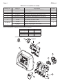
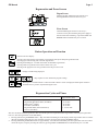
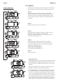
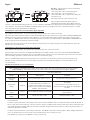
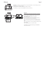
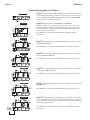
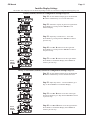
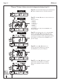
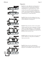
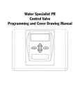
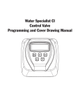
Water Specialist EE
Control Valve
Programming and Cover Drawing Manual
Page 2
EE Manual
EE Manual
Page 3
Table of Contents
EE Front Cover and Drive Assembly.................................................................................................................................. 4
Regeneration and Error Screens, Button Operations and Functions................................................................................... 5
User Displays ...................................................................................................................................................................... 6
Configuration Settings ........................................................................................................................................................ 7
Setting Regeneration Cycle Times .................................................................................................................................... 10
Installer Display Settings .................................................................................................................................................. 11
Diagnostics........................................................................................................................................................................ 13
Page 4
EE Manual
EE Front Cover and Drive Assembly
Drawing No.
1
2
3
4
5
6
Not Shown
Not Shown
Order No.
V3175EE-01
V3107-01
V3106-01
V3408EE-02BOARD
V3110
V3109
V3186
V3186-01
V3178
Description
WS1EE FRONT COVER ASSEMBLY
WS1 MOTOR
WS1 DRIVE BRACKET & SPRING CLIP
WS1THRU2L EEPCBRD MAV/ALT REPL
WS1 DRIVE GEAR 12X36
WS1 DRIVE GEAR COVER
WS1 AC ADAPTER 110V-12V
WS1 AC ADAPTER CORD ONLY
WS1 Drive Back Plate
Quantity
1
1
1
1
3
1
1
1
Refer to Control Valve Service Manual for other drawings and part numbers.
AC Adapter
Supply Voltage
Supply Frequency
Output Voltage
Output Current
U.S.
120 V AC
60 Hz
12 V AC
500 mA
International
230V AC
50 Hz
12 V AC
500 mA
When replacing the battery, align
positives and push down to fully seat.
Correct
Battery
Orientation
Battery replacement is
3 volt lithium coin cell
type 2032.
Battery Fully Seated
4
1
6
5
3
2
EE Manual
Page 5
Regeneration and Error Screens
Regen Screen
Displays the time remaining in the current cycle.
Pressing REGEN advances to the next cycle.
Error Screen
Alternated flashing Err and error code every 3
seconds. Clear by dissconnecting the power supply at
the PC board and reconneting, or press the NEXT and
REGEN buttons simutaneously for 3 seconds.
Button Operation and Function
Scrolls to the next display.
Pressing once and releasing will schedule a regeneration at the preset delayed regeneration time.
Pressing again and releasing will cancel the regeneration.
Pressing and holding for 3 seconds will initiate an immediate regeneration
Pressing while in regeneration will advance to the next cycle.
Pressing in the program levels will go backwards to the previous screen
Changes variable being displayed.
Key sequence to lock and unlock program settings.
Holding for 3 seconds initiates a control reset.The software version is displayed and the piston returns to
the home/service position, resynchronizing the valve.
Regeneration Cycles and Times
Cycle
Range of times (min.)
st
1. Backwash 1 (upflow)
2. Regenerant Draw/Slow Rinse (downflow)
3. Backwash 2nd (upflow)
4. Fast Rinse (downflow)
5. Regenerant Refill (with treated water)
6. Service (downflow)
1 - 20 or OFF
1 - 99 or OFF
1 - 20 or OFF
1 - 20 or OFF
0.1 - 99.9 or OFF
The user can initiate manual regeneration. The user has the option to request the manual regeneration at the delayed regeneration
time or to have the regeneration occur immediately:
1. Pressing and releasing the REGEN button. “ ” will flash towards Regen on the display and the regeneration will occur at the
delayed regeneration time. The user can cancel the request by pressing and releasing the REGEN button.
2. Pressing and holding the REGEN button for approximately 3 seconds will immediately start the regeneration. The user cannot
cancel this request, except by resetting the control by pressing NEXT and REGEN buttons simultaneously for 3 seconds.
Page 6
EE Manual
User Displays
General Operation
When the system is operating, one of five displays may be shown.
Pressing NEXT will alternate between the displays shown below.
User 1
Typical user display. If volume is selected in Configuration
Settings Step 3CS, shows volume remaining to regeneration. If
volume is not selected in Configuration Settings Step 3CS, this
screen will not be shown. If a meter is not used this display will
not change.
User 2
Displays number of days to next regeneration.
User 3
Displays flow rate in gallons per minute. If a meter is not used
this display will be shown but 0 will be displayed.
This screen will not be shown if 7 day or 28 day is selected in
Configuration Settings Step 3CS.
User 4
Displays total flow in gallons since last reset. If a meter is
not used this display will be shown but 0 will be displayed.
This screen will not be shown if 7 day or 28 day is selected in
Configuration Settings Step 3CS.
PRESS THE DOWN ▼ ARROW
FOR 3 SECONDS TO RESET TO 0.
User 5
Shows current time.
Setting Time of Day
Push NEXT button until time of day screen is displayed. Press and
hold the ▲ or ▼ arrow until the SET indicator is displayed, and
the hour flashes. Press the ▲ or ▼ button until the correct hour is
displayed.
Then press the NEXT button. The minutes will flash. Press the
▲ or ▼ arrow until the correct minute is displayed.
Press the NEXT button to return to the Display Screens. Time of
day should only need to be set after power outages lasting more
than 8 hours, if the battery has been depleted and a power outage
occurs, or when daylight saving time begins or ends. If a power
outage lasting more than 8 hours occurs, the time of day will flash
on and off which indicates the time of day should be reset. If a
power outage lasts less than 8 hours and the time of day flashes on
and off, the time of day should be reset and the battery replaced.
EE Manual
Page 7
Configuration Settings
Step 1CS
Step 1CS – Press ▲ and ▼ buttons simultaneously for 5 seconds and release. If screen in Step 2CS does not
appear, the lock on the valve is activated. To unlock press ▼, NEXT, REGEN, ▲ in sequence, then press ▲
and ▼ buttons simultaneously for 5 seconds and release.
Step 2CS
Step 2CS – Choose 1.0 for 1”, 1.25 for 1.25”, 1.5 for 1.5”, 2.0L for 2L, 2.0 for 2” valve ¹. Press NEXT to go
to Step 3CS. Press REGEN to exit Configuration Settings.
Note: When using the WS2 valve, if “2L” is set instead on “2.0” for valve type, when the valve is in
regeneration and the piston drives to the “Draw” cycle the piston will stall and generate a 1002 error code.
Clear error code by pressing “NEXT” and “REGEN” simultaneously until the valve resets, then re-program
to proper valve type setting.
Step 3CS
Step 3CS – Press the ▲ or ▼ buttons to select one of the following:
• If Volume (gallons) is selected the regeneration will occur after the specific volume has been used or on the
day override (if selected) whichever comes first.
• If 28/Volume (gallons) is selected the regeneration will occur on the day (1 through 28) selected in Installer
Display Settings. If a meter is not used the total flow and flow rate user displays and the volume display in
Diagnostics will be shown as 0.
• If 7/Volume (gallons) is selected the regeneration will occur on the selected day(s) of the week (see
instructions contained in Installer Display Settings). If a meter is not used the total flow and flow rate user
displays and the volume display in Diagnostics will be shown as 0.
• If 28 is selected the regeneration will occur on the day (1 through 28) selected in Installer Display Settings.
The total flow and flow rate user displays and the volume display in Diagnostics will not be shown even if a
meter is used.
• If 7 is selected the regeneration will occur on the selected day(s) of the week (see instructions contained in
Installer Display Settings). The total flow and flow rate user displays and the volume display in Diagnostics
will not be shown even if a meter is used.
Press NEXT to go to Step 4CS. Press REGEN to return to previous step.
Step 4CS
Step 4CS – Press the ▲ or ▼ buttons to select to regenerate immediately on 0 or at delayed time.
Immediately on 0 can only be selected if Volume (gallons) was selected in step 3CS and a meter must be
installed. Delay is the only option for the other Step 3CS selections. Press NEXT to go to Step 5CS. Press
REGEN to return to previous step.
¹ When using the WS2 control valve, the circuit board software must have meter selection choices
of 2.0 and 2.0L. The WS2 valve must be set for the 2.0 meter selection during programming. If the
software version does not have both the 2.0 and 2.0L selections, consult your equipment supplier
for a replacement circuit board. When using the WS2L valve with older version software that does
not have both 2.0 and 2.0L selection choices, the valve must be set to 2.0 during programming. If a
WS2L valve is being used with newer version software that has both 2.0 and 2.0L selection choices,
the valve must be set to 2.0L during programming.
Page 8
EE Manual
Step 5CS – - Allows selection of one of the following
using the ▲ or ▼ buttons:
• the Control Valve to have no hard water bypass;
• the Control Valve to act as an alternator; or
• the Control Valve to have a separate source during the
regeneration cycle.
Step 5CS
Volume
Volume
Select OFF when none of these features are used.
Only use Clack No Hard Water Bypass Valves or
Clack Motorized Alternating Valves (MAV) with these
selections. Clack No Hard Water Bypass Valves (1” or 1.25” V3070FF or V3070FM) are not designed to be used with the alternator or separate
source functions. The V3063 and V3063BSPT motorized alternating valves are not designed to be used as a no hard water bypass or separate
source inlet if the pressure differential is more than 60 psi.
Configuring the Control Valve for No Hard Water Bypass Operation:
Select nHbP for control operation. For no hard water bypass operation the three wire connector is not used.
Selection requires that a connection to MAV or a Clack No Hard Water Bypass Valve is made to the two pin connector labeled ALTERNATOR
DRIVE located on the printed circuit board. If using a MAV, the A port of the MAV must be plugged and the valve outlet connected to the B
port. When set to nHbP the MAV will be driven closed before the first regeneration cycle that is not FILL or SOFTENING or FILTERING, and
be driven open after the last regeneration cycle that is not FILL.
NOTE: If the control valve enters into an error state during regeneration mode, the no hard water bypass valve will remain in its current state
until the error is corrected and reset.
Configuring the Control Valve for Separate Source Operation:
Select nHbP for control operation. For separate source operation the three wire connector is not used.
Selection requires that a connection to a Clack Motorized Alternator Valve (MAV) is made to the two pin connector labeled ALTERNATOR
DRIVE located on the printed circuit board. The C port of the MAV must be connected to the valve inlet and the A port connected to the separate
source used during regeneration. The B port must be connected to the feed water supply.
When set to nHbP the MAV will be driven closed before the first regeneration cycle, and be driven open after the last regeneration cycle.
NOTE: If the control valve enters into an error state during regeneration mode, the MAV will remain in its current state until the error is
corrected and reset.
Selecting the Control Valve to act as an alternator:
Prior to starting the programming steps, connect the interconnect cable to each control valve board’s three pin connector labeled
“INTERCONNECT”. Also connect the meter cord to either control valve to the three pin connector labeled “METER”.
Valve Programming Steps
Configuration
Settings
Step 3CS
Select Volume
Set Volume
Configuration
Settings
Step 4CS
Set regeneration time option to “On O”.
Set regeneration time option to “On O”.
Configuration
Settings
Step5CS
Set to ALTA
Connect ALTA valve to the MAV’s A
port and connect the MAV’s two pin wire
connector to the two pin connector labeled
“DRIVE” on the ALTA valve
Set to ALTb
Connect ALTb valve to the MAV’s B port. No
connections between the ALTB valve and the MAV
are made.
Installer Display
Setting
Step 2I
Enter the Volumetric Capacity for the System
Enter the Volumetric Capacity for the System (the
same as Valve A)
Installer Display
Setting
Step 3I
Set Day Over ride to “oFF”
Set Day Over ride to “oFF”
NOTE: If the control valve is in an error state during regeneration mode the MAV will close the B port and keep open the A port until the error is
corrected and reset.
For Clack Corporation alternator systems using the WS1, WS1.25, WS1.5 and WS2L valves the stand by tank will be periodically brought on
line for a short time to keep its bed fresh. The logic is that once a tank is in standby and the time has passed either 6 AM or 6 PM (18:00) at the
next and all subsequent 6 AM and 6 PM times the stand by tank will be brought on line until 10 gallons (37.8 liters) has passed through it. It
will then be placed back on standby.
For Clack Corporation alternator systems using the WS2 valve, when NEXT is pressed after selecting ALTA or ALTb, a display will allow the
user to set the amount of pre-service rinse time for the stand by tank just prior to returning to service.
Press NEXT to go to Step 6CS. Press REGEN to return to previous step.
EE Manual
Page 9
Step 6CS
Step 6CS – Set duration of the special rinse cycle to be performed prior to a valve returning to Service.
Selectable from 1 - 20 minutes or OFF.
Only viewed if 2.0 is set in 2CS, and ALTA or ALTb is set in 5CS.
Volume
Press NEXT to go to Step 7CS. Press REGEN to return to previous step.
Step 7CS
EXIT TO
DISPLAY
SCREENS
Step 7CS
Selecting the use of an outside signal to initiate a regeneration:
Selection only matters if a connection is made to the two pin
connector labeled DP SWITCH located on the printed circuit
board. Following is an explanation of the options:
oFF - Feature not used.
on0 - If the dP switch is closed for an accumulative time of 2
minutes a regeneration will occur immediately.
dELy - If the dP switch is closed for an accumulative time of 2
minutes a regeneration will occur at the scheduled regeneration
time.
HoLd - If the dP switch is closed a regeneration will be prevented
from occurring.
Not viewed if Step 5CS is set to ALTA or ALTb.
Press NEXT to exit Configuration Settings. Press REGEN to
return to previous step.
Page 10
EE Manual
Setting Regeneration Cycle Times
Step 1CT - Press NEXT and ▼ simultaneously for 5 seconds and release.
Step 1CT
If screen in Step 2CT does not appear, the lock on the valve is activated. To
unlock press ▼, NEXT, REGEN, ▲ in sequence, then press NEXT and ▼
simultaneously for 5 seconds and release.
Step 2CT - Select between SOFTENING or FILTERING.
Step 2CT
Flow
Rate
AM
Time
PM Days To
Regen
Set
Volume
X1000
Regen
Backwash
Brine
Rinse
Fill
When set to FLTr, 7CT is not set to off, and 2CS is set to 1.0, a fixed 30
second Backwash is automatically added to the regen cycle program after
Rinse 6CT. The status display for this extra backwash will appear as just
another cycle step in sequence.
Press NEXT to go to Step 3CT. Press REGEN to exit Regeneration
Cycle Times.
Step 3CT
Step 3CT - Adjust the length of the backwash from 1-20 minutes or OFF
using the ▲ or ▼ buttons.
Press NEXT to go to Step 4CT. Press REGEN to return to previous step.
Step 4CT
Step 4CT - Adjust the length of the regenerant draw from 1-99 minutes or
OFF using the ▲ or ▼ buttons.
Press NEXT to go to Step 5CT. Press REGEN to return to previous step.
Step 5CT
Step 5CT - Adjust the length of the second backwash from 1-20 minutes
or OFF using the ▲ or ▼ buttons.
Press NEXT to go to Step 6CT. Press REGEN to return to previous step.
Step 6CT
Step 6CT - Adjust the length of rinse from 1-20 minutes or OFF using the
▲ or ▼ buttons.
Press NEXT to go to Step 7CT. Press REGEN to return to previous step.
Step 7CT
Step 7CT - Adjust the length of fill from 0.1-99.0 minutes or OFF. WS2
valves are shipped from the factory with a refill flow control of 2.2 gpm (8.3
lpm). All other control valves are shipped from the factory with a refill flow
control of 0.5 gpm (1.9 lpm).
EXIT TO
DISPLAY
SCREENS
Press NEXT to exit Regeneration Cycle Times. Press REGEN to return to
previous step.
EE Manual
Page 11
Installer Display Settings
One of three sets of displays will be shown depending on what was selected in Configuration Settings Step 3CS.
Volume (Gallons) selected in Configuration Settings Step 3CS
Step 1I
Step 1I - To enter Installer Display press the NEXT and
▲ buttons simultaneously for 5 seconds and release.
Step 2I
Step 2I - Volumetric capacity in gallons to regeneration.
Press NEXT to go to Step 3I. Press REGEN to exit
Installer Display.
Step 3I
Step 3I - Adjust day override from 1 - 28 or OFF.
Press NEXT to go to Step 4I. Press REGEN to return to
previous step.
Step 4I
Step 4I - Use ▲ or ▼ buttons to set the regen hour.
Press NEXT to go to Step 5I. Press REGEN to return to
the previous step.
Step 5I
Step 5I - Use ▲ or ▼ buttons to set the regen minutes.
Press NEXT to exit Installer Display. Press REGEN to
return to previous step.
EXIT TO
DISPLAY
SCREENS
28 Day or 28/Volume (Gallons) selected in Configuration Settings Step 3CS
Step 1I
Step 1I - To enter Installer Display press the NEXT and
▲ buttons simultaneously for five seconds and release.
Step 2I
Step 2I - Adjust days from 1 - 28. Press NEXT to go to
Step 3I. Press REGEN to exit Installer Display.
Step 3I
Step 3I - Use ▲ or ▼ buttons to set time of the regen
hour. Press NEXT to go to Step 4I. Press REGEN to return
to previous step.
Step 4I
EXIT TO
DISPLAY
SCREENS
Step 4I - Use ▲ and ▼ buttons to set the regen minutes.
Press NEXT to exit Installer Display. Press REGEN to
return to previous step.
Page 12
EE Manual
7 Day or 7/Volume (Gallons) selected in Configuration Settings Step 3CS
Step 1I
Step 1I - To enter Installer Display press the NEXT and
▲ buttons simultaneously for 5 seconds and release.
Step 2I
the week.
Step 2I - Use ▲ or ▼ buttons to set the current day of
Default = 2 (Monday)
1 = SUNDAY
2 = MONDAY
3 = TUESDAY
4 = WEDNESDAY
5 = THURSDAY
6 = FRIDAY
7 = SATURDAY
Press NEXT to go to Step 3I. Press REGEN to exit
Installer Display.
EXIT TO
DISPLAY
SCREENS
Step 3I
Step 3I - Scroll through days 1 to 7 using the NEXT
button. Use the ▲ or ▼ buttons to turn regen on or
off for each individual day (regen indicator on means
regeneration will happen). After completing the 7th day,
press NEXT to go to Step 4I. Press REGEN to go to
previous display.
Step 4I
Step 4I - Use the ▲ or ▼ buttons to set
the regen hour. Press NEXT to go to Step 5I.
Press REGEN to go to previous display.
Step 5I
Step 5I - Use the ▲ or ▼ buttons to set the
regen minutes. Press NEXT to exit Installer
Display. Press REGEN to return to previous
display.
EE Manual
Page 13
Diagnostics
Step 1D
Step 1D - Press ▲ and ▼ buttons simultaneously for
5 seconds and release. Then press ▲ and ▼ buttons
simultaneously for 2 seconds and release. If screen
in Step 2D does not appear the lock on the valve is
activated. To unlock press ▼, NEXT, REGEN, ▲ in
sequence, then press ▲ and ▼ buttons simultaneously
for 5 seconds and release. Then press ▲ and ▼ buttons
simultaneously for 2 seconds and release.
Step 2D
Step 2D - Display shows the number of days since a
regeneration last occurred. Press NEXT to go to Step
3D. Press REGEN to exit Diagnostics.
Step 3D
Step 3D - Display shows the volume of water treated
in gallons treated since the last regeneration. If Volume
(gallons), 28/Volume (gallons), or 7/Volume (gallons)
was selected in Step 3CS and no meter is installed this
display will read 0. Press NEXT to go to Step 4D. Press
REGEN to return to previous step.
Step 4D
Step 4D - Display shows the days in service since start
up. Press NEXT to go to Step 5D. Press REGEN to
return to previous step.
Step 5D
EXIT TO
DISPLAY
SCREENS
Step 5D - Display shows the total number of
regeneration cycles since start up. Press NEXT to exit
Diagnostics. Press REGEN to return to previous step.
Page 14
EE Manual
EE Manual
Page 15
Page 16
Revision History:
10/13/2008
PAGES 11-13:
Updated Motorized Alternating Valve and No Hard Water Bypass instructions.
1/5/2009
PAGES 9:
Updated the instructions for Step 7CT.
3/16/2009
PAGES 10 & 11:
Revised Step 2CS.
Revised Step 5CS.
3/30/2009
Page order changed after page 6.
PAGE 7:
Added note to Step 2CS.
4/1/2009
PAGE 8:
Corrected display header in Step 5CS.
PAGE 9:
Corrected display header in Step 6CS.
Form No. V3435EE – 4/1/2009
EE Manual