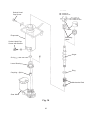
1
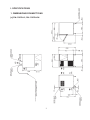
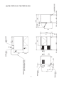
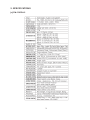
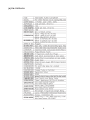
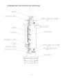
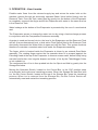
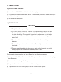
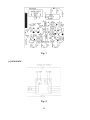
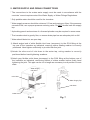
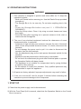
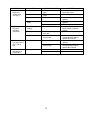
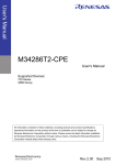
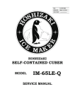
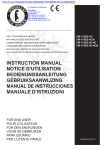
NO.
E2EB-814
ISSUED: AUG. 21, 2010
REVISED:
HOSHIZAKI
MODULAR ICE MAKER
MODEL
FM-170EE-HC
FM-170EE-HCN
FM-170EE-50-HC
FM-170EE-50-HCN
SERVICE MANUAL
CONTENTS
PAGE
I. SPECIFICATIONS--------------------------------------------------------------------------------------1
1. DIMENSIONS/CONNECTIONS-----------------------------------------------------------------1
[a] FM-170EE-HC, FM-170EE-HCN------------------------------------------------------------1
[b] FM-170EE-50-HC, FM-170EE-50-HCN---------------------------------------------------2
2. SPECIFICATIONS-----------------------------------------------------------------------------------3
[a] FM-170EE-HC-----------------------------------------------------------------------------------3
[b] FM-170EE-HCN---------------------------------------------------------------------------------4
[c] FM-170EE-50-HC-------------------------------------------------------------------------------5
[d] FM-170EE-50-HCN-----------------------------------------------------------------------------6
II. GENERAL INFORMATION--------------------------------------------------------------------------7
1. CONSTRUCTION-----------------------------------------------------------------------------------7
2. OPERATION - How it works-------------------------------------------------------------------- 10
3. TIMER BOARD------------------------------------------------------------------------------------- 11
[a] SOLID-STATE CONTROL------------------------------------------------------------------ 11
[b] TIMER BOARD-------------------------------------------------------------------------------- 11
[c] SEQUENCE------------------------------------------------------------------------------------ 12
III. INSTALLATION INSTRUCTIONS--------------------------------------------------------------- 15
1. UNPACKING---------------------------------------------------------------------------------------- 15
2. LOCATION------------------------------------------------------------------------------------------ 16
3. INSTALLATION------------------------------------------------------------------------------------ 17
4. ELECTRICAL CONNECTIONS---------------------------------------------------------------- 17
5. WATER SUPPLY AND DRAIN CONNECTIONS------------------------------------------ 19
IV. OPERATING INSTRUCTIONS------------------------------------------------------------------ 20
1. START UP------------------------------------------------------------------------------------------- 20
2. PREPARING THE ICEMAKER FOR LONG STORAGE--------------------------------- 21
V. MAINTENANCE-------------------------------------------------------------------------------------- 22
1. PERIODICAL CLEANING----------------------------------------------------------------------- 22
2. CLEANING OF WATER SYSTEM------------------------------------------------------------ 24
VI. TECHNICAL INFORMATION--------------------------------------------------------------------- 28
1. WATER CIRCUIT AND REFRIGERANT CIRCUIT---------------------------------------- 28
2. WIRING DIAGRAM------------------------------------------------------------------------------- 29
3. TIMING CHART------------------------------------------------------------------------------------ 30
[a] PRINCIPLE OF OPERATION-------------------------------------------------------------- 30
[b] PROTECTORS-------------------------------------------------------------------------------- 30
4. PERFORMANCE DATA-------------------------------------------------------------------------- 32
[a] FM-170EE-HC, FM-170EE-50-HC-------------------------------------------------------- 32
[b] FM-170EE-HCN, FM-170EE-50-HCN--------------------------------------------------- 33
VII. SERVICE DIAGNOSIS---------------------------------------------------------------------------- 34
1. NO ICE PRODUCTION-------------------------------------------------------------------------- 34
i
2. LOW ICE PRODUCTION------------------------------------------------------------------------ 36
3. OTHERS--------------------------------------------------------------------------------------------- 36
VIII. REMOVAL AND REPLACEMENT OF COMPONENTS--------------------------------- 38
1. REFRIGERATION CIRCUIT-------------------------------------------------------------------- 38
[a] APPLICABLE PARTS------------------------------------------------------------------------ 38
[b] SERVICE INSTRUCTIONS---------------------------------------------------------------- 38
[c] REFRIGERANT-------------------------------------------------------------------------------- 38
[d] COMPRESSOR------------------------------------------------------------------------------- 39
[e] EVAPORATOR CASING-------------------------------------------------------------------- 39
[f] CONDENSER----------------------------------------------------------------------------------- 39
[g] CONDENSER COOLING FAN MOTOR------------------------------------------------ 39
[h] DRIER-------------------------------------------------------------------------------------------- 39
[i] THERMOSTATIC EXPANSION VALVE--------------------------------------------------- 40
2. EVAPORATOR ASSEMBLY-------------------------------------------------------------------- 40
3. FAN MOTOR---------------------------------------------------------------------------------------- 42
4. FLOAT SWITCH----------------------------------------------------------------------------------- 42
5. CONTROL WATER VALVE--------------------------------------------------------------------- 43
ii
I. SPECIFICATIONS
1. DIMENSIONS/CONNECTIONS
[a] FM-170EE-HC, FM-170EE-HCN
1
[b] FM-170EE-50-HC, FM-170EE-50-HCN
2
2. SPECIFICATIONS
[a] FM-170EE-HC
3
[b] FM-170EE-HCN
4
[c] FM-170EE-50-HC
5
[d] FM-170EE-50-HCN
6
II. GENERAL INFORMATION
1. CONSTRUCTION
Self-contained flaker models FM-170EE-HC, FM-170EE-HCN, FM-170EE-50-HC
and FM-170EE-50-HCN include Water Supply, Evaporator, Condensing and Control
Assemblies.
Top Panel
Door
Front Panel (Left)
Power Supply Cord
Front Cover
Louver
Air Filter
Bin Control Switch
Spout
Drainboard
Evaporator
Reservoir
Circuit Breaker
Compressor
Control Box
Gear Motor
Condenser
Fan Motor
7
ICE MAKING UNIT [FM-170EE-HC, FM-170EE-50-HC]
8
ICE MAKING UNIT [FM-170EE-HCN, FM-170EE-50-HCN]
9
2. OPERATION - How it works
Potable water flows from the external supply tap and enters the water inlet on the
machine, passes through an electrically operated Water Valve before flowing into the
Reservoir Tank. From the Tank, water flows by gravity into the bottom of the Evaporator
to completely surround the Auger and fill the Evaporator with water to the same level as
in the Reservoir Tank.
Water leakage at the bottom of the Evaporator is prevented by the use of a mechanical
seal.
The Evaporator serves to change the water into ice by using a heat exchange process
in conjunction with the Compressor/Condenser assembly.
As water is used and turned into ice, the level in the Evaporator and the Reservoir Tank
will fall. At a pre-determined level, a dual action Float Switch fitted to the Reservoir Tank
electrically commands the Water Valve to open and refill the Tank. This system functions
therefore to maintain a constant water level inside the Evaporator assembly.
The Auger, which is located inside the Evaporator is driven by an external Gear Motor
assembly. The rotating Auger carries the ice upwards where it is pressed against the
Extruding Head at the top of the Evaporator to remove excess water, before finally being
extruded and broken into irregular shapes and sizes of ice by the Flake/Nugget Cutter
or into cubelet ice.
The continuous flow of ice is then pushed into the Ice Spout and falls by gravity into the
Storage Bin below.
Moving the Operation Switch, located on the Control Box, to the “ON” position starts
an automatic and continuous icemaking process. When the Storage Bin has filled with
ice, the Bin Control Switch, located at the top of the Storage Bin, stops the icemaking
process. When ice is removed from the Storage Bin, the Bin Control Switch will
automatically reset and restart the icemaking process.
10
3. TIMER BOARD
[a] SOLID-STATE CONTROL
1) An exclusive HOSHIZAKI solid-state control is employed.
2) A Printed Circuit Board (hereafter called “Timer Board”) includes a stable and highquality control system.
3) No adjustment is required.
[b] TIMER BOARD
CAUTION
1. Fragile, handle very carefully.
2. A timer board contains CMOS (Complementary Metal-Oxide
Semiconductor) integrated circuits, which are susceptible to failure due
to static discharge. It is especially important to either wear an anti-static
wrist strap or touch a metal part of the machine before servicing to be
static free.
3. Do not touch the electronic devices on either side of the board to prevent
damage.
4. Do not change wiring and connections. Especially, never misconnect
terminals.
5. Do not repair the electronic devices or parts on the board in the field.
Always replace the whole board assembly when it fails.
The icemaker is controlled by the Timer Board for the following purposes:
1) To prevent the Gear Motor and the Compressor from starting or stopping
simultaneously.
2) To reduce ice remaining in the Evaporator.
3) To protect the unit in case of low water and low water pressure.
4) To protect the unit from short cycling if the Bin Control resets quickly.
11
Fig. 1
[c] SEQUENCE
Fig. 2
12
CONTROL (CTL)
PROTECT (PRT)
X1 RELAY
(GEAR MOTOR)
X2 RELAY
(COMPRESSOR)
PART CODE
MODEL
RATING
T 1
T2
T3
T4
T5
T6
437305-02
H2AA144C02
24 VAC 50/60Hz
60 ± 15 sec.
90 ± 22 sec.
150 ± 45 sec.
Max. 1 sec.
Max. 0.25 sec.
Max. 1 sec.
Fig. 3
Note: “T” (time) functions of the Timer Board are non-adjustable.
13
Functions of Terminals
1) Terminals 1, 2
Power supply AC 24V.
2) Terminals 3, 4
Control X1 (GM) and X2 (CM) Relays.
When closed, energize X1 (GM) in 1 sec. and X2 (CM) in 60 sec.
When opened, de-energize X1 (GM) in 150 sec. and X2 (CM) in 90 sec.
3) Terminals 5, 6
Control X1 (GM) and X2 (CM) Relays.
When opened, de-energize X1 (GM) and X2 (CM) immediately.
When closed, energize X1 (GM) in 1 sec. and X2 (CM) in 60 sec.
4) Terminals 7, 8, 9
X1 (GM) contacts.
8 is a movable contact, 7 is a make contact, and 9 is a break contact.
5) Terminals 10, 11
Control X2 (CM) Relay.
When opened, de-energize X2 (CM) immediately.
When closed, energize X2 (CM) immediately.
Note:1.X2 Relay is a single pole, normally open relay, and its terminals are mounted on
the relay itself.
2.The above operation times are median. See Fig. 3 for details.
3. GM = Gear Motor
CM = Compressor
14
III. INSTALLATION INSTRUCTIONS
WARNING
The installation must be carried out by qualified personnel, in accordance
with current regulations, according to the manufacturer’s instructions.
1. UNPACKING
WARNING
Children should not be allowed in reach of the packaging elements (plastic
bags and expanded polystyrene) as they are potential sources of danger.
CAUTION
1. Do not lift or manoeuvre the carton by using the shipping bands.
2.Remove shipping carton, tape(s) and packing. If packing material is left
in the icemaker, it will not work properly.
Top Panel
Door
Front Panel (Left)
Power Supply Cord
Front Cover
Louver
Air Filter
Fig. 4
1) After removing the packaging, make sure that the icemaker is in good condition. If in
doubt, please do not use the equipment.
2) Remove the shipping tape holding the Door and Front Panel.
15
3) Open the Door, take out the package containing accessories, and check the contents:
a) Installation Kit
Inlet Hose
1
Outlet Hose
1
Adjustable Leg
4
b) Scoop
1
4) Remove the Front Panel (Left) and Top Panel. See Fig. 5.
5) Remove the protective plastic film from the panels. If the icemaker is exposed to the
sun or to heat, remove the film after the icemaker cools.
Top Panel
Protective Plastic Film
Front Panel (Left)
Adjustable Leg
Front Panel (Left): Remove the screws. Lift up and
pull toward you.
Top Panel:
Remove the screws and lift up.
Fig. 5
2. LOCATION
WARNING
1.This icemaker is not intended for outdoor use. Normal operating ambient
temperature should be within 5°C to 40°C. Normal operating water
temperature should be within 5°C to 35°C. Operation of the icemaker,
for extended periods, outside of these normal temperature ranges may
affect production capacity.
2.The icemaker should not be located next to ovens, grills or other high
heat producing equipment.
3.The location should provide a firm and level foundation for the
equipment.
16
4.Allow 15 cm clearance at rear, sides and top for proper air circulation
and ease of maintenance and/or service should they be required.
5.This appliance is not suitable for installation in an area where a water jet
could be used and where dripping is not allowed.
6.Do not place anything on top of the icemaker or in front of the Louver.
7.This icemaker will not work at subfreezing temperatures. To prevent
damage to the water supply line, drain the icemaker when air
temperature is below zero (see “II. 2. PREPARING THE ICEMAKER
FOR LONG STORAGE” in the instruction manual).
8.The noise from this icemaker is 55 dB or less.
9.Avoid prolonged exposure of the appliance to direct sunlight.
10.This appliance contains flammable refrigerant in its cooling unit;
maintenance and recharging must therefore only be carried out by
authorized technicians.
3. INSTALLATION
* Incorrect installation can cause harm to people, animals or things, for which the
manufacturer cannot be held responsible.
1)Position the icemaker in the selected permanent site.
2)Level the icemaker in both the left-to-right and front-to-rear directions by adjusting the
legs.
4. ELECTRICAL CONNECTIONS
WARNING
THIS APPLIANCE MUST BE EARTHED
This icemaker requires an earth that meets the national and local
electrical code requirements. To prevent possible severe electrical shock
to individuals or extensive damage to equipment, install a proper earth
wire to the icemaker. Remove the plug from the mains socket before any
maintenance, repairs or cleaning is undertaken.
* This appliance requires a separate 220 - 240VAC, 13A supply. The electrical supply
must be protected by a suitable circuit breaker.
17
* The main control box fuse is rated at 6A and should only be replaced by a qualified
service engineer.
* Usually an electrical permit and services of a licensed electrician are required.
* If the supply cord and the plug should need to be replaced, it should only be done by a
qualified service engineer.
For the U.K. and the Republic of Ireland only
* The wires in the mains lead are coloured in accordance with the following code:
Green & Yellow = Earth
Blue = Neutral
Brown = Live
As the colours of the wire in the mains lead of this appliance may not correspond with
the coloured markings identifying the terminals in your plug, proceed as follows:
The wire which is coloured Green-and-Yellow must be connected to the terminal in
or coloured Green or
the plug which is marked with the letter E or by the symbol
Green-and-Yellow. The wire which is coloured Blue must be connected to the terminal
which is marked with the letter N or coloured Black. The wire which is coloured Brown
must be connected to the terminal which is marked with the letter L or coloured Red.
* Should the socket outlets in the installation site not be suitable for the plug supplied
with your product, the plug must be removed (cut off if it is moulded on plug) and an
appropriate plug fitted.
If the non-rewirable plug has been cut from the power supply cord, it must be
disposed of. There should be no attempt to reuse it. Inserting such a plug into a socket
elsewhere presents a serious risk of electrical shock.
* The non-rewirable plug must never be used without a fuse cover being fitted.
The correct replacement for the detachable fuse cover is identifiable from the
manufacturer’s reference number stamped on the plug.
Supply of replacement fuse covers can be obtained from Hoshizaki Parts/Service
Centres.
Fuses should be rated at 13A and approved to BS 1362.
18
5. WATER SUPPLY AND DRAIN CONNECTIONS
*The connections to the mains water supply must be made in accordance with the
countries’ current requirements of the Water Supply or Water Fittings Regulations.
* Only potable water should be used for the icemaker.
* Water supply pressure should be minimum 0.5 bar and maximum 8 bar. If the pressure
exceeds 8 bar, use a proper pressure reducing valve. Do NOT throttle back the supply
tap.
* A plumbing permit and services of a licensed plumber may be required in some areas.
* The icemaker drain is gravity flow, so ensure drain pipe has an adequate pitch or fall.
* Water should drain into an open trap.
1) Attach angled end of white flexible inlet hose (accessory) to the G3/4 fitting at the
top rear of the icemaker as indicated, ensuring rubber sealing washer is correctly
positioned. Hand tighten sufficiently to provide leak free joint.
2)A ttach the other end of inlet hose to the water tap, noting washer is correctly
positioned before hand tightening as above.
3)Attach grey flexible outlet hose (accessory) to the R3/4 fitting at the bottom rear of
the icemaker as indicated, confirming fitment of rubber washer before finally hand
tightening the joint. This pipe can be cut to length as necessary to suit position of main
drain.
Water Supply
Inlet G3/4
Inlet Hose
Water Supply Tap
Drain Outlet
R3/4
Inlet Hose
Outlet Hose
Fig. 6
19
Fig. 7
IV. OPERATING INSTRUCTIONS
WARNING
1. This icemaker is designed to produce and store edible ice. To keep the
icemaker hygienic:
* Wash your hands before removing ice. Use the Plastic Scoop provided
(accessory).
* The Storage Bin is for ice use only. Do not store anything else in the
Bin.
* C l ean the Storage Bin before use (see “V. 1. PERIODICAL
CLEANING”).
* Keep the Scoop clean. Clean it by using a neutral cleaner and rinse
thoroughly.
* Close the Door after removing ice to prevent entrance of dirt, dust or
insects into the Storage Bin.
2. The use of any electrical equipment involves the observance of some
fundamental rules. In particular:
* Instances of high humidity and moisture increase the risk of electrical
short circuits and potential electrical shocks. If in doubt, disconnect the
icemaker.
*Do not damage the power cord or pull it in order to disconnect the
icemaker from the feed network.
*Use the attachment plug as the main power disconnect switch for the
icemaker.
*Appliance must be positioned so that the plug is accessible.
*Do not touch the attachment plug and other electrical parts or operate
the Operation Switch with damp hands.
*This appliance is not suitable for unsupervised use by young children
or aged or infirm persons.
*Do not attempt to modify the icemaker. Only qualified personnel may
disassemble or repair the appliance.
3. All parts are factory-adjusted. Improper adjustments may result in failure.
4. If the unit is turned off, wait for at least 3 minutes before restarting the
icemaker to prevent damage to the Compressor.
1. START UP
1)Check that the power supply cord is disconnected.
2)With the Front Panel (Left) removed, check that the Operation Switch on the Control
Box is turned on.
20
Circuit
Breaker (6A)
Motor
Protector (3A)
Operation
Switch
Control Box
Front Panel
(Left)
Control Box
Condenser
Fig. 8
Fig. 9
3)Replace the Front Panel (Left) and Top Panel in their correct position.
4)Open the water supply tap.
5)Connect the power supply and energise.
6)The following should occur in sequence:
a) Water Reservoir will fill.
b) Gear Motor will start.
c) Compressor will start.
IMPORTANT
1. Check the conditions and quality of the ice production.
2. Do not use ice produced in the trial run. It might be contaminated with
foreign matter in the water circuit. Discard or flush down the drain.
3. Clean the Storage Bin before use (see “V. 1. PERIODICAL CLEANING”).
2. PREPARING THE ICEMAKER FOR LONG STORAGE
WARNING
When shutting off the icemaker for an extended time, drain out all water
from the water line and remove ice from the Storage Bin. The Storage Bin
should be cleaned and dried. Drain the icemaker to prevent damage to the
water supply line at sub-freezing temperatures. Shut off the icemaker until
the proper ambient temperature is resumed.
1) Close the water supply tap.
21
2) Run the icemaker (for about 10 minutes) until the Compressor and the Gear Motor
stop automatically.
3) Unplug the icemaker and remove the Front Panel (Left).
4) Remove the Inlet Hose from the water tap, and drain the Hose.
5) Unhook the Drain Hose (Water Level Gauge).
6) Drain water, and refit the Drain Hose, the Inlet Hose and the Front Panel in their
correct position.
7) Remove all ice from the Storage Bin. Clean and dry the Bin.
V. MAINTENANCE
WARNING
1. Before carrying out any cleaning or maintenance operations, unplug the
icemaker from the electrical supply network.
2. A trained service person should check and clean the Condenser at least
once a year.
3. This appliance must not be cleaned by use of a water jet.
4.To prevent possible damage, do not clean the plastic parts with water
above 40°C or in a dishwasher.
1. PERIODICAL CLEANING
[1] Exterior
Wipe the exterior at least once per week with a clean, soft cloth. Use a damp cloth
containing a neutral cleaner to wipe off grease or dirt.
[2] Storage Bin Interior Cleaning/Sanitisation (as required)
1)Open the Storage Bin Door, and remove all ice.
2)Remove the Drain Cap located in the base of the Storage Bin.
3)Wash the Bin Liner, Plastic Spill Flap and Drain Cap with a neutral non-abrasive
cleaner. Rinse thoroughly.
22
Note: Take care not to damage the Bin Control Actuator at the top of the Bin.
4)Mix 5 litres of water with 18 ml of 5.25% sodium hypochlorite solution in a suitable
container or the recommended Hoshizaki sanitiser as directed.
5)Soak a clean sponge or cloth with the solution and wipe all the surfaces of the Bin
Liner, Plastic Spill Flap and Drain Cap.
6)Refit the Drain Cap. Wipe the inside surface of the Bin Door with the solution. Close
the Bin Door.
7)The remaining solution can be used to sanitise utensils.
Note: Do not wipe dry or rinse after sanitising, but allow to air dry.
[3] Ice Scoop, Bin Door Exterior and Door Handle Cleaning/Sanitisation (Daily)
1) Either mix 3 litres of water with 11 ml of 5.25% sodium hypochlorite solution in a
suitable container, or the recommended Hoshizaki sanitiser as directed.
2) Soak the Scoop in the solution for more than 3 minutes. Rinse thoroughly, and shake
to remove surplus liquid.
Note: Using a cloth to dry may re-contaminate.
3) Use a neutral cleaner to wash the Storage Bin Door exterior, especially the Handle at
the top of the Door. Rinse with a clean cloth and fresh water.
4) Soak a clean cloth with the sanitising solution, and wipe the surfaces. Use fresh water
and a clean cloth to rinse.
[4] Air Filter
Plastic mesh Air Filters remove dirt or dust from the air, and keep the Condenser from
getting clogged. If the Filters get clogged, the icemaker’s performance will be reduced.
Remove and clean the Air Filter at least twice per month:
1)Slide the Air Filter off the Louver.
2)Clean the Air Filter by using a vacuum cleaner. When
severely clogged, use warm water and a neutral cleaner
to wash the Air Filter.
3)Rinse and dry the Air Filter thoroughly, and place it in
position.
23
Air Filter
Louver
Fig. 10
2. CLEANING OF WATER SYSTEM
WARNING
1. HOSHIZAKI recommends cleaning this unit at least twice a year. More
frequent cleaning, however, may be required in some existing water
conditions.
2. Always wear rubber gloves, eye protectors, apron, etc. for safe handling
of the cleaner and sanitiser.
3. Use the cleaners and sanitisers recommended by Hoshizaki. Contact
your local Hoshizaki office for further details. (The instructions below
give an example of those recommended cleaners and sanitisers.)
4. Never mix cleaning and sanitising solutions in an attempt to shorten
cleaning time.
5. Wipe off any splashed or spilt cleaner/sanitiser immediately.
6. Do not use any ammonia type cleaners on any part of the icemaker.
<STEP 1>
Dilute the solutions with water as follows:
Cleaning solution:“Nickel-Safe Ice Machine Cleaner” by The Rectorseal Corporation
or similar. Prepare approximately 3 L of solution as directed on the
container.
Sanitising solution: 30 mL of 5.25% sodium hypochlorite with 7.6 L of water or the
Hoshizaki recommended sanitiser as directed on the container.
IMPORTANT
For safety and maximum effectiveness, use the solutions immediately after
dilution.
<STEP 2>
Use the cleaning solution to remove lime deposits in the water system.
1) Unplug the icemaker.
2) Close the water supply tap.
24
3) Remove all ice from the Storage Bin to avoid contamination by the cleaner.
4) Remove the Front Panel (Left) and the Top Panel.
5) Unhook the Drain Hose and drain the water system.
6) Refit the Drain Hose in its correct position.
7) Remove the Control Water Valve by releasing the Fitting Nut. Do not lose the
Packing.
8) Remove the Cover of the Reservoir. Remove any loose debris or scale.
9) Carefully fill the Reservoir with the solution to the overflow point. If necessary, use a
small brush to clean the inside of the Reservoir.
10) Refit the Cover of the Reservoir and the Control Water Valve in their correct position.
Note: This unit will start immediately the power is turned on when the Reservoir is
full.
11) Loose fit the Top Panel and refit the Front Panel (Left) in position.
12) Allow the icemaker to stand for about 10 minutes, then plug in the icemaker to make
ice with the solution until the machine automatically stops.
13) Open the water supply tap and allow the machine to continue icemaking for a further
15 minutes. Unplug the icemaker.
14) Remove the Front Panel (Left).
15) Unhook the Drain Hose and drain the water system.
16) Refit the Front Panel (Left) in its correct position.
17) Plug in the icemaker to supply water to the Reservoir.
18) Unplug the icemaker when the Gear Motor starts.
19) Repeat items 14) to 18) at least twice to fully flush the solution.
20) Pour warm water into the Storage Bin to melt any ice down the drain.
Note:1.If the machine has heavy deposits of scale, repeat the complete cleaning
procedure.
2.Do not increase the proportion of cleaning solution to shorten cleaning times,
as this may lock the Auger when completing item 12).
25
<STEP 3>
Note: Sanitising should always be completed after cleaning or alternately as an
individual procedure if conditions exist to make it necessary.
Use 2.8 lit. of the sanitizing solution to sanitize the icemaker.
21) Close the water supply tap.
22) Follow items 4) to 20) to complete sanitisation of the water system.
<STEP 4>
Use the remaining sanitising solution to sanitise removable parts.
23) Remove the Front Panel (Left) and lift off the Top Panel.
24) Remove the Snap Pin, the Shaft and the Activator (See Fig. 11) from the Bin Control
Assembly.
25) Remove the Thumbscrews, the Spout and the Spout Packing (See Fig. 11).
1. Shaft
2. Activator
3. Snap Pin
4. Spout
5. Thumbscrew
6. Spout Packing
Fig. 11
26
26) Immerse these parts in the sanitizing solution for about 15 minutes.
27) Rinse these parts thoroughtly with clean water.
IMPORTANT
If the solution is left on these parts, they will corrode.
28) Refit the removed parts in reverse order.
29) Close the water supply tap.
Coil
30) Remove the Control Water Valve by
releasing the Fitting Nut. Do not lose the
Packing (See Fig. 12).
Do not remove
Filter
Packing
31) Remove the Mesh Filter from the inlet
side of the Valve (See Fig. 12).
32) Clean the Mesh using a brush. Rinse
with fresh water.
Fig. 12
33) Refit the Mesh into the Valve and the Valve into its correct position.
34) Open the water supply tap and check for leaks.
35) Refit the Top and Front Panels securely with the screws.
36) Plug in the icemaker and make ice for 30 minutes.
37) Unplug the icemaker and pour warm water into the Storage Bin to melt the ice.
38) Plug in the icemaker and start the automatic icemaking process.
IMPORTANT
1. After cleaning, do not use ice made from the sanitizing solution. Be
careful not to leave any solution in the Storage Bin.
2. Follow carefully any instructions provided with the bottles of cleaning or
sanitizing solution.
3. Never run the icemaker when the Reservoir is empty.
27
VI. TECHNICAL INFORMATION
1. WATER CIRCUIT AND REFRIGERANT CIRCUIT
28
2. WIRING DIAGRAM
29
3. TIMING CHART
[a] PRINCIPLE OF OPERATION
When the Operation Switch is moved to the “ON” position, water is supplied through the
Control Water Valve. This cycle continues until the Reservoir is full and the Float Switch
signals to close the Water Valve. The Gear Motor will then start in 1 second and the
Compressor in 60 seconds. This starts the normal icemaking process.
During normal operation, the icemaker will stop only when the Ice Storage Bin is full and
the Bin Control activates. This will automatically reset to resume normal operation.
POWER ON
Float Switch
BIN FULL
UPPER
LOWER
Control Water Valve
ON
OFF
Bin Control Switch
ON
OFF
Gear Motor
ON
OFF
Fan Motor
ON
OFF
Compressor
ON
OFF
1sec
90sec
60sec
150sec
1sec
60sec
Fig. 13
[b] PROTECTORS
1) Pressure Switch
If the Pressure Switch activates, the Gear Motor, Fan Motor and Compressor stop
simultaneously in 0.25 sec. When the switch resets at the correct pressure, the icemaker
starts the icemaking process in the same way as startup. (See “[a] PRINCIPLE OF
OPERATION.”)
Although the Pressure Switch will automatically reset, the Compressor will stop for at
least 5 minutes for protection in case the head pressure rises to activate the Pressure
Switch again. If this happens, the icemaker will start and stop repeatedly without making
ice until the cause of head pressure rise is removed.
2) Motor Protector (GM)
When the Protector activates, the Gear Motor, Fan Motor and Compressor stop
simultaneously in 0.25 sec. The Protector has to be manually reset. Check and resolve
the cause of the Protector tripping before pressing the Reset.
30
POWER ON
Float Switch
PRESSURE SWITCH
MOTOR PROTECTOR
OFF
RESET
UPPER
LOWER
Control Water Valve
ON
OFF
Pressure Switch
ON
OFF
Gear Motor
ON
OFF
Fan Motor
ON
OFF
Compressor
ON
OFF
1sec
0.25sec
60sec
1sec
60sec
Fig. 14
3) Low Water Control
The icemaker will stop when the water level in the Reservoir falls below the lower
float level and is not refilled to the upper float level within 90 seconds due to either an
interruption in the water supply or low water pressure. When the water reaches the
upper float level, the icemaker will automatically resume the icemaking process.
POWER ON
Float Switch
LOW WATER
UPPER
LOWER
Control Water Valve
ON
OFF
Gear Motor
ON
OFF
Fan Motor
ON
OFF
Compressor
ON
OFF
1sec
90sec
60sec
150sec
Fig. 15
31
1sec
60sec
4. PERFORMANCE DATA
[a] FM-170EE-HC, FM-170EE-50-HC
Ice Production Capacity (kg/day)
180
160
140
120
100
80
60
40
20
0
10/10
21/15
32/21
Ambient Temp Water Temp (°C)
Electric Consumption (KWH/day)
500
495
490
485
480
475
470
465
460
455
450
10/10
21/15
32/21
Ambient Temp Water Temp (°C)
2.5
18
2
Head Pressure (bar)
14
12
Suction Pressure (bar)
16
1.5
10
8
1
6
Suction
Pressure(bar)
Head Pressure(bar)
4
2
0
0.5
0
10/10
21/15
Ambient Temp Water Temp (°C)
32
32/21
[b] FM-170EE-HCN, FM-170EE-50-HCN
Ice Production Capacity (kg/day)
160
140
120
100
80
60
40
20
0
10/10
21/15
32/21
Ambient Temp Water Temp (°C)
Electric Consumption (KWH/day)
505
500
495
490
485
480
475
470
10/10
21/15
32/21
Ambient Temp Water Temp (°C)
2.5
18
2
Head Pressure (bar)
14
12
1.5
10
8
1
6
Suction
Pressure(bar)
Head Pressure(bar)
4
2
0
0.5
0
10/10
21/15
Ambient Temp Water Temp (°C)
33
32/21
Suction Pressure (bar)
16
VII. SERVICE DIAGNOSIS
1. NO ICE PRODUCTION
PROBLEM
[1] The icemaker
will not start.
CHECK
a) Power Supply
b) Circuit Breaker
(Control Box)
c) Transformer
Receptacle (on
upper part of
Control Box)
d) Transformer
e) Water Valve
f) Water Supply Tap
g) Plug and
Receptacle
(Control Box)
h) Bin Control
POSSIBLE CAUSE
1. OFF position.
2. Loose connections.
3. Bad contacts.
4. Blown fuse.
5. Unplugged.
1. OFF position.
2. Bad contacts.
1. Disconnected.
1. Coil winding opened.
1. Coil winding opened.
2. Strainer clogged.
1. Closed.
2. Water failure.
1. Disconnected.
2. Terminal out of Plug
or Receptacle.
1. Bad contacts.
2. Activator does not
move freely.
[2] Water does not
stop, and the
icemaker will
not start.
[3] Water has
been supplied,
but the
icemaker will
not start.
i) Protection Switch
1. Bin Control defective.
a) Water Control
Relay
b) Float Switch
2. Switch turned on.
1. Contacts fused.
2. Coil winding opened.
1. Bad contacts.
c) Hoses
a) Water Control
Relay
b) Gear Motor
Protector
2. Float does not move
freely.
1. Disconnected.
1. Bad contacts.
1. Tripped.
c) Gear Motor Relay
(Control Timer)
1. Coil winding opened.
2. Bad contacts.
d) Control Timer
(Printed Circuit
Board)
1. Broken.
34
REMEDY
1. Move to ON position.
2. Tighten.
3. Check for continuity and
replace.
4. Replace.
5. Plug in.
1. Move to ON position.
2. Check for continuity and
replace.
1. Connect.
1. Replace.
1. Replace.
2. Clean.
1. Open.
2. Wait till water is supplied.
1. Connect.
2. Insert Terminal back in
position.
1. Check for continuity and
replace.
2. Clean Axle and its
corresponding holes or
replace Bin Control.
1. Check Bin Control and
replace.
2. Check Protection Switch.
1. Replace.
2. Replace.
1. Check for continuity and
replace.
2. Clean or replace.
1. Connect.
1. Check for continuity and
replace.
1. Find the cause, resolve it,
and press Reset Button on
Motor Protector.
1. Replace.
2. Check for continuity and
replace.
1. Replace.
PROBLEM
[3] (Continued)
[4] Gear Motor
starts, but
Compressor
will not start or
operates
intermittently.
CHECK
e) Gear Motor
Protect Relay
POSSIBLE CAUSE
1. Coil winding opened.
2. Bad contacts.
f) Pressure Switch
1. Dirty Air Filter or
Condenser.
2. Ambient temperature
too warm.
3. Fan not rotating.
4. Refrigerant
overcharged.
5. Refrigerant line or
components plugged.
6. Bad contacts.
a) X2 Relay on
Control Timer
b) Starter
c) Start Capacitor or
Run Capacitor
d) Compressor
e) Power Supply
[5] Gear Motor
and
Compressor
start, but no ice
is produced.
a) Refrigerant Line
7. Loose connections.
1. Bad contacts.
2. Coil winding opened.
1. Bad contacts.
2. Coil winding opened.
3. Loose connections.
1. Defective.
1. Loose connections.
2. Motor winding opened
or earthed.
3. Motor Protector
tripped.
1. Circuit Ampacity too
low.
1. Gas leaks.
2. Refrigerant line
clogged.
35
REMEDY
1. Replace.
2. Check for continuity and
replace.
1. Clean.
2. Check for recommended
temperature.
3. See 3 - [1] - a).
4. Recharge.
5. Clean and replace Drier.
6. Check for continuity and
replace.
7. Tighten.
1. Check for continuity and
replace.
2. Replace Timer.
1. Check for continuity and
replace.
2. Replace.
3. Tighten.
1. Replace.
1. Tighten.
2. Replace.
3. Find out the cause of
overheat or overcurrent.
1. Install a larger-sized
conductor.
1. Check for leaks with a leak
detector. Reweld leak,
replace Drier and charge
with refrigerant. The
amount of refrigerant is
marked on Nameplate or
Label.
2. Replace the clogged
component.
2. LOW ICE PRODUCTION
PROBLEM
[1] Low ice
production.
CHECK
a) Refrigerant Line
b) High-side
Pressure Too
High
c) Expansion Valve
(not adjustable)
POSSIBLE CAUSE
1. Gas leaks.
2. Refrigerant line
clogged.
3. Overcharged.
1. Dirty Air Filter or
Condenser.
2. Ambient temperature
too warm.
3. Fan rotating too slow.
4. Bad ventilation.
1. Low-side pressure too
low.
2. Low-side pressure too
high.
REMEDY
1. See 1 - [5] - a).
2. Replace the clogged
component.
3. Recharge.
1. Clean.
2. Check for recommended
temperature.
3. See 3 - [1] - a).
4. Remove anything blocking
vents.
1. Replace.
2. See if Expansion Valve
Bulb is mounted properly,
and replace the valve if
necessary.
3. OTHERS
PROBLEM
[1] Abnormal
noise
CHECK
a) Fan Motor
b) Compressor
c) Refrigerant Lines
d) Gear Motor
e) Evaporator
POSSIBLE CAUSE
1. Bearing worn out.
2. Fan blade deformed.
3. Fan blade does not
move freely.
1. Bearings worn out, or
cylinder valve broken.
2. Mounting pad out of
position.
1. Rub or touch lines or
other surfaces.
1. Bearing or Gear
wear/damage.
1. Too much pressure
loss.
2. Scale on inside wall of
Freezing Cylinder.
3. Water does not flow
from Reservoir into
Evaporator (air staying
in Evaporator).
36
REMEDY
1. Replace.
2. Replace fan blade.
3. Replace.
1. Replace.
2. Reinstall.
1. Reset or secure pipes.
1. Replace.
1. Replace.
2. Remove Auger. Use a
solution of lime removing
cleaner to clean
periodically.
If water is found to surpass
the following levels, install
a conditioner.
Hardness 50 ppm
Silica
30 ppm
3. Straighten bent hose.
PROBLEM
[2] Overflow from
Reservoir
(Water does
not stop.)
CHECK
a) Water Supply
b) Water Valve
c) Float Switch
d) Water Control
Relay
[3] Gear Motor
Protector
operates
frequently.
a) Power Supply
Voltage
b) Evaporator Assy
c) Bin Control
[4] Icemaker does
not stop even if
Bin is full of
ice.
a) Bin Control
[5] Water leaks at
the bottom of
Evaporator
a) Mechanical Seal
POSSIBLE CAUSE
1. Water pressure too
high.
1. Diaphragm does not
close.
1. Bad contacts.
1. Bad contacts.
2. Coil winding opened.
1. Too high or too low.
1. Bearings or Auger
worn out.
1. Activator does not
move freely.
1. Contacts fused.
2. Activator does not
move freely.
1. Worn out.
2. Bad assembly.
37
REMEDY
1. Install a Pressure
Reducing Valve.
1. Clean or replace.
1. Check for continuity and
replace.
1. Check for continuity and
replace.
2. Replace.
1. Connect the unit to a
power supply of proper
voltage.
1. Replace Bearing or Auger.
1. Clean Axle and its
corresponding holes or
replace Bin Control.
1. Check for continuity and
replace.
2. Clean Axle and its
corresponding holes or
replace Bin Control.
1. Replace.
2. Clean and assemble.
VIII. REMOVAL AND REPLACEMENT OF COMPONENTS
1. REFRIGERATION CIRCUIT
WARNING
This machine contains flammable refrigerant. Do not attempt to break into the
refrigerant circuit unless qualified, competent and authorised to do so.
If any component of the refrigeration circuit requires removal or replacement, please
contact the manufacturer:
HOSHIZAKI EUROPE LIMITED
Telford 70 Stafford Park 7, Telford, Shropshire TF3 3BQ UK
Tel: +44 (0)1952-291777
Fax: +44 (0)1952-292777
[a] APPLICABLE PARTS
Refrigerant (R290)
Compressor
Evaporator Casing
Air-cooled Condenser
Air-cooled Condenser Fan Motor
Drier
Thermal Expansion Valve (with MOP)
[b] SERVICE INSTRUCTIONS
Always restore the original bindings after servicing the refrigeration circuit. Otherwise,
vibration may cause overstress and damage to the circuit, resulting in refrigerant leak.
After replacing the Evaporator or Auger, run the icemaker for 30 minutes to produce ice,
check for impurities, and discard.
[c] REFRIGERANT
The HFC-free refrigerant is flammable and sealed in the refrigeration system. Although
the refrigerant does not leak out under normal usage, take utmost care when handling
this icemaker so as not to cause any damages to the system. In the case of accidental
damage to the refrigeration system causing refrigerant leak, do not create a source of
ignition in the area. Do not operate electrical switches or plugs in the area, do not use
naked flame. Immediately ventilate the area by opening doors and/or windows.
38
[d] COMPRESSOR
The Compressor absorbs the low-pressure refrigerant gas vaporized in the Evaporator
(to reduce the pressure inside the Evaporator), compresses the refrigerant into
high-temperature high-pressure gas, and sends it out to the Condenser.
The hermetic-type Compressor is efficient in refrigeration, and the refrigeration circuit is
designed to endure long hours of operation. The Compressor is mounted on vibration
damping rubber to prevent transmission of vibration. In case of accidental overload, the
Case Thermostat or Overload Relay will shut down the Compressor. The Reset Button
must be pressed to reset the Overload Relay.
[e] EVAPORATOR CASING
The Evaporator Casing is a thin and rigid stainless steel pipe tightly coiled around with a
copper tube and solder finished. The refrigerant flows through a very narrow path in the
Expansion Valve with a sudden drop of pressure and evaporates by absorbing heat of
vaporization from the Evaporator Casing. The water supplied inside the Evaporator
Casing is deprived of heat and forms ice film which will be scraped and moved up by
the Auger.
[f] CONDENSER
The Condenser refrigerates and liquefies the high-temperature high-pressure refrigerant
gas discharged from the Compressor into high-pressure liquid refrigerant. The
Condenser is air-cooled.
A dirty Condenser will significantly reduce the refrigeration efficiency and performance,
and will also shorten the service life of the components (especially refrigeration circuit).
The frequency of cleaning depends on the installation conditions.
a) Air-cooled Condenser (Spiral tube type)
A copper tube is attached on a spiral aluminum plate with high heat conductivity to
promote heat radiation, and a Fan Motor is also provided for forced air cooling.
Use a vacuum cleaner or brush to remove dirt and dust between the spiral fins. Be
careful not to bend the fins.
[g] CONDENSER COOLING FAN MOTOR
The Fan Motor cools the Air-cooled Condenser and sends air to condense refrigerant
gas inside the Condenser.
[h] DRIER
The Drier uses desiccants (molecular sieves + activated alumina) to absorb moisture in
the refrigeration circuit. The built-in filter also corrects foreign matter in the refrigeration
39
circuit to prevent troubles with valves clogged with dirt or moisture.
[i] THERMOSTATIC EXPANSION VALVE
The Expansion Valve throttles high-pressure liquid refrigerant into low-temperature
low-pressure state by adiabatic expansion and maintains the proper amount of
refrigerant supply depending on the Evaporator load. The Thermostatic Expansion
Valve controls the valve position to regulate the superheat (difference between
evaporating temperature and suction gas temperature). No superheat control is
available from outside.
To check the Expansion Valve for proper operation, remove the Bulb while the
Compressor is running. If the suction pressure rises, the Expansion Valve is working
normally.
Note: Do not leave the Bulb removed for a long time while the Compressor is
running. The Compressor may fail due to liquid return.
2. EVAPORATOR ASSEMBLY
WARNING
This machine contains flammable refrigerant. Do not attempt to disassemble and
service the evaporator assembly unless qualified, competent and authorised to do
so.
If any component of the evaporator assembly requires removal or replacement, please
contact the manufacturer:
HOSHIZAKI EUROPE LIMITED
Telford 70 Stafford Park 7, Telford, Shropshire TF3 3BQ UK
Tel: +44 (0)1952-291777
Fax: +44 (0)1952-292777
[a] APPLICABLE PARTS
See Fig. 16.
40
Socket Head
Cap Screw
FM-170EE-HC
FM-170EE-50-HC
FM-170EE-HCN
FM-170EE-50-HCN
Cutter
Evaporator
Extruding
Head
Socket Head Cap
Screw with Washer
Auger
O-ring
Lower Bearing
Ring
Coupling - Spline
Mechanical Seal
Gear Motor
Fig. 16
41
3. FAN MOTOR
1) Unplug the icemaker.
2) Remove the Top Panel, the Front Panel (Left) and the Left Side Panel.
3) Remove the wire connectors from the Fan Motor leads.
4) Remove the Fan Motor Bracket and the Fan Motor.
5) Install the new Fan Motor onto the Bracket, and re-fix the Fan Blade.
6) Refit the Fan Motor Assembly and the wire connectors.
7) Refit the panels in their correct position.
8) Plug in the icemaker.
4. FLOAT SWITCH
1) Unplug the icemaker.
2) Close the water supply tap.
3) Remove the Inlet Hose from the water tap, and drain the Hose.
4) Remove the Top Panel and the Front Panel (Left).
5) Drain the water system using the Drain Hose (Water Level Gauge).
6) Disconnect the wire connectors of the Float Switch leads.
7) Unfasten the flanged top, turn it and then remove the Float Switch.
8) Install the new Float Switch.
9) Re-connect the switch leads using new connectors.
10) Refit the panels in their correct position.
11) Open the water supply tap.
12) Plug in the icemaker, and check the Float Switch functions normally.
42
5. CONTROL WATER VALVE
1) Unplug the icemaker.
2) Close the water supply tap.
3) Remove the Inlet Hose from the water tap, and drain the Hose.
4) Remove the Top Panel and the Front Panel (Left).
5) Disconnect the Terminals from the Control Water Valve.
6) Loosen the Fitting Nut on the Control Water Valve Inlet, and remove the Control
Water Valve. Do not lose the Packing inside the Fitting Nut.
7) Remove the Reservoir Inlet Cover from the Control Water Valve.
8) Install the new Control Water Valve.
9) Assemble the removed parts in the reverse order of which they were removed.
10) Open the water supply tap.
11) Check for water leaks.
12) Refit the panels in their correct position.
13) Plug in the icemaker.
43