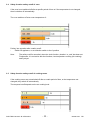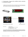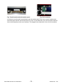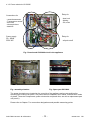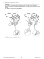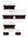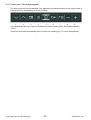
1
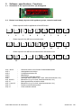
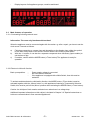
SERVICE MANUAL
COOKING
© Electrolux Distriparts
Muggenhofer Straße 135
D-90429 Nürnberg
Germany
Fax +49 (0)911 323 1022
DGS-TDS-N
Edition:
05.09
Publ.-Nr.:
599 521 367
685
EN
Built-in appliances
and floor-mounted
stoves
with „Avantgarde“
input electronics
Table of contents
1.
ESD=electrostatic discharge .............................................................................................. 3
2.
2.1
2.2
2.3
2.3.1
2.3.2
Software specifications, Functions ..................................................................................... 4
Illustration of the input electronics (UI) Avantgarde .............................................................. 4
Button / and display layouts of all appliance groups, countries and brand .......................... 4
Main features of operation ................................................................................................... 5
Clock setting following network reset .................................................................................. 5
Electronic child-safe function .............................................................................................. 5
3.
3.1
3.2
3.3
3.4
3.5
Functions of appliance ........................................................................................................ 6
Oven functions, capacities and small consumer - appliance-specific ............................... 6
Pyrolitical cleaning - Explanation ......................................................................................... 8
High-speed heating - Explanation ........................................................................................ 9
Safety function safety cutoff of oven .................................................................................. 10
Safety function safety cutoff of cooking zones .................................................................. 10
4.
4.1
4.1.1
4.1.2
4.1.3
4.1.4
4.1.4.1
4.1.4.2
4.1.5
4.1.6
4.2
4.2.1
4.2.2
4.2.3
Functional parts - Component data, installation situation, dismantling .............................. 11
Functional parts - Oven control ......................................................................................... 11
Input electronic (UI) Avantgarde ......................................................................................... 11
Power electronic OVC2000 ............................................................................................... 13
Temperatursensor PT500 ................................................................................................. 14
Door locking systems ........................................................................................................ 15
Door lock ........................................................................................................................... 15
Door locking system, motorics with door-switch light ....................................................... 17
Door switch for the light ..................................................................................................... 17
Light bar in the control panel ............................................................................................. 18
Functional parts - Cooking setting control ......................................................................... 19
Power controller ................................................................................................................ 19
Input electronic HOC2000 and Input module ..................................................................... 20
cooking zone power board HOC2000 ............................................................................... 22
5.
5.1
5.2
5.3
5.4
Technical equipment ......................................................................................................... 24
Temperature safety device ................................................................................................ 24
Fan after-running ............................................................................................................... 24
Measure against wrong electrical connection ................................................................... 24
Oven rack protective circuit ............................................................................................... 25
6.
6.1
6.2
6.3
6.3.1
6.3.2
6.4
Fault diagnosis/ What to do if ...? ...................................................................................... 26
Alarmmanagement (Faultcodes) ....................................................................................... 26
Measuring the temperature sensor ................................................................................... 27
Demo Mode input electronic Avantgarde ........................................................................... 28
Activating/deactivating Version a ....................................................................................... 28
Activating / deactivating Version b ..................................................................................... 29
Factory test / Türverriegelungstest .................................................................................... 30
7.
7.1
7.2
7.3
7.4
7.5
7.6
7.7
Wiring diagram / measuring points ................................................................................... 31
Connection Point Overview ............................................................................................... 31
Example circuit diagram OVC 1000 .................................................................................. 32
Example circuit diagram OVC 2000 .................................................................................. 33
Example circuit diagram SOEC ........................................................................................ 34
Example circuit diagram Prisma ....................................................................................... 35
Example circuit diagram HOC 2000 .................................................................................. 36
Operative Equipment Overview ......................................................................................... 37
Changes .......................................................................................................................................... 38
DGS-TDS-N 05.09 A. B. © Electrolux
-2-
599 521 367
EN
1.
ESD=electrostatic discharge
As the single electronic interfaces are not protected internally against statical electricity and are
partially open, you must pay attention to that, in case of a repair, there will be a potential
compensation via the housing of the appliance (touch it) in order to neutralize a possible charging
and to prevent a damaging of the affected electronic interface.
You also have to be careful with those electronics delivered as spare parts, which have to be put
out of the ESD protective package only after a potential compensation (discharge of possible
statical electricity).
If a potential compensation with an existing static electricity is not executed, it does not mean that
the electronic is demaged directly. Consequential damages may result due to the damaging of
internal structures which arise only in case of load through temperature and current.
Endangered are all assembly groups which are provided with control entries, wire paths lying open
and free-accessible processors.
DGS-TDS-N 05.09 A. B. © Electrolux
-3-
599 521 367
EN
2.
Software specifications, Functions
2.1
Illustration of the input electronics (UI) Avantgarde
2.2
Button / and display layouts of all appliance groups, countries and brand
-
Button layout for built-in appliances of the AEG brand
1
2
3
4
5
6
7
8
9
10
14
11
12
- o uButton
ect
SC layout for the M2 floor-mounted cooker
-
Button layout for the M2 flour mounted cooker with double-oven
13
Key 1 and 2
Key 3
Key 4
Key 5
Key 6
Key 7
Key 8 and 9
Key 10
Key 11 and 12
Key 13
Key 14
7
-
Selection button oven function forwards/backwards
Avantgarde menu button
Confirmation button OK
Main Button
Fast heating selection switch
Selection switch MODE (e.g. clock, meat thermometer, etc.)
Minus/Plus (e.g. for clock, meat thermometer, etc.)
Meat thermometer selection switch
Minus/Plus (e.g. for clock, meat thermometer, etc.)
Double-oven selection switch
Clock selection switch
DGS-TDS-N 05.09 A. B. © Electrolux
-4-
599 521 367
EN
-
Display layouts of all appliance groups, countries and brand
2.3 Main features of operation
2.3.1 Clock setting following network reset
Information: The oven only functions with set time!
When the appliance must be connected again with the mains e.g. after a repair, you have to set the
clock anew. Proceed as follows:
a)
b)
c)
Following connection or a power loss and depending on the display class, either the symbol
for the time of day blinks or the arrow in front of the the ‘time of day’ symbol blinks.
With the +/- buttons, it can also be a separate component when necessary (input module) to
set the time of day.
If need be, confirm with the MODE button (=Timer button) The appliance is ready for
operation.
2.3.2 Electronic child-safe function
Basic prerequisites:
-
Power supply voltage is connected
No oven function selected.
If the appliance is equipped with a Main Switch, then this must be
activated
To activate and deactivate the child-safety function, the MODE button (=Timer button) must be
activated together with the „„Minus“ button, or, with appliances featuring a Temperature Selection
Switch, this must be put into the „Minus“ position when activating the MODE button (=Timer button).
Caution: the child-proof lock remains activated even when there is a voltage drop.
Additional important information on this subject is included in Chapter 3.6 "Special instructions on
hob/oven communication in floor-mounted appliances".
DGS-TDS-N 05.09 A. B. © Electrolux
-5-
599 521 367
EN
3.
Functions of appliance
3.1
Oven functions, capacities and small consumer - appliance-specific
Brand / Market:
AEG Germany and Export
Oven class
w ith/w ithout pyrolytical cleaning
Electronic:
OVC2000
oven function
Pos.0 (OFF)
Pos.1
Pos.2
Pos.3 (top-/bottom el.)
Pos.4
Pos.5
Pos.6
Pos.7 (keeping warm)
Pos.8
Pos.9
Pos.10
heating elements (Watt)
top
bottom
rear
grill element element
element
element
suggested temperature Boost
1900
1000
1000
1900
150
200
200
180
300
300
80
30
150
120/80
B
A
B
A
Manual booster
A
B
Brand / Market:
AEG Export Frankreich
Oven class
Avantgarde-w ith/w ithout pyrolytical cleaning
Electronic:
OVC 2000
oven function
Pos.0 (OFF)
Pos.1
Pos.2
Pos.3 (top-/bottom el.)
Pos.4
Pos.5
Pos.6
Pos.7 (keeping warm)
Pos.8
Pos.9
Pos.10
X
X
X
-
X
X
X
X
X
X
X
X
150
200
200
180
300
300
80
30
150
120/80
B
A
B
C
X
X
X
-
A
B
C
X
X
X
X
X
X
X
X
X
X
X
X
X
X
AEG UK
Oven class
Avantgarde-w ith/w ithout pyrolytical cleaning
Electronic:
OVC 2000
oven function
suggested temperature Boost
Pos.0 (OFF)
Pos.1
300
Pos.2
300
Pos.3
150
B
Pos.4
200
A
Pos.5 (top-/bottom el.)
200
B
Pos.6
180
A
Pos.7
150
B
Pos.8
150
Pos.9
30
Pos.10 (keeping warm)
80
Pos.11
120/80
A
B
DGS-TDS-N 05.09 A. B. © Electrolux
X
X
X
X
X
X
X
X
cooking
fan
40
X
X
X
X
X
X
X
X
X
X
X
X
X
X
Brand / Market:
X
X
X
X
heating elements (Watt)
top
bottom
rear
grill element element
element
element
suggested temperature Boost
1900
1000
1000
1900
Manual booster
Manual booster
X
X
X
X
X
X
X
heating elements (Watt)
top
bottom
rear
grill element element
element
element
1900
1000
1000
1900
X
X
X
X
X
X
X
X
X
X
X
X
X
X
X
X
X
X
X
X
X
X
X
X
-6-
small loads (Watt)
oven lamp
cooling fan back wall
25
40
cooking
fan
40
X
X
X
X
X
X
X
X
X
oven lamp
side wall
25
Power (W)
current ampere
(W)
X
X
X
X
X
X
X
X
X
X
3030
3030
2090
3030
2990
1990
2090
105
1090
3030
13,2
13,2
9,1
13,2
13,0
8,7
9,1
0,5
4,7
13,2
X
X
X
X
X
X
X
X
X
X
small loads (Watt)
oven lamp
oven lamp
cooling fan
back wall
side wall
25
40
25
X
X
X
X
X
X
X
X
X
X
X
X
X
X
X
X
X
X
X
X
X
X
X
X
X
X
X
X
X
Motor
current ampere
Grillspieß Power (W)
(W)
5
X
X
X
-
3030
3030
2090
3035
2995
1995
2090
105
1090
3030
13,2
13,2
9,1
13,2
13,0
8,7
9,1
0,5
4,7
13,2
X
cooking
fan
40
X
X
X
X
X
X
small loads (Watt)
oven lamp
cooling fan back wall
25
40
X
X
X
X
X
X
X
X
X
X
X
X
X
X
X
X
X
X
X
X
X
current ampere
oven lamp
(W)
side wall Power (W)
25
X
2990
13,0
X
1990
8,7
X
3030
13,2
X
3030
13,2
X
2090
9,1
X
3030
13,2
X
2130
9,3
X
1090
4,7
X
105
0,5
X
2090
9,1
X
3030
13,2
X
X
599 521 367
EN
Brand / Market:
Electrolux-Standherde (M2)
Oven class
Avantgarde-w ith/w ithout pyrolytical cleaning
Electronic:
OVC2000
oven function
Pos. 0 (OFF)
Pos. 1
Pos.2 (top-/bottom el.)
Pos. 3
Pos. 4
Pos. 5
Pos. 6 (keeping warm)
Pos. 7
Pos. 8
Pos. 9
Booster "AUTO"
suggested temperature Boost
180
200
190
200
250
80
30
30
120/80
A
A
DGS-TDS-N 05.09 A. B. © Electrolux
grill
element
1900
X
X
-
heating elements (Watt)
top
bottom
rear
element element
element
1000
1000
1900
X
X
X
X
-
X
X
X
X
-
X
-7-
cooking
fan
40
X
X
X
X
X
X
X
X
X
X
X
small loads (Watt)
oven lamp
cooling fan back wall
25
40
X
X
X
X
X
X
X
X
X
X
X
X
X
X
X
X
oven lamp
side wall Power (W)
25
X
X
X
X
X
X
X
X
X
2030
2090
3030
3030
2990
2090
1105
105
2030
current ampere
(W)
8,8
9,1
13,2
13,2
13,0
9,1
4,8
0,5
8,8
599 521 367
EN
3.2
Pyrolitical cleaning - Explanation
°C
end of heating phase
500
400
cooling phase
door locked
300
200
door unlocked
100
room temperature
120 P3 150 P2
90
min
P1
Fig. heating-up curve temperature (°C) / time (min
With the Pyroluxe self-cleaning system the residues in the interior are carbonized to ashes at high
temperatures. The centre of gravity temperature of the muffle is approx. 500°C.
A max. selection of three pyrolysis durations (P…) can be made per appliance class and
equipment.
Pyrolysis duration (Heating period)
P1
P2
P3
>
>
>
Note:
Heating period
Heating period
Heating period
150min
120min
90min
In appliances which are equipped with two pyrolysis durations, P2 corresponds to the
pyrolysis duration P3.
DGS-TDS-N 05.09 A. B. © Electrolux
-8-
599 521 367
EN
The oven door is locked at a centre of gravity temperature of the muffle of approx. 312°C, after a
heating-up time of approx. 11 min.
The oven door is unlocked at a centre of gravity temperature of the muffle of approx. 204°C. The
moment depends on the selected pyrolytic duration.
The cooling fan is running at an increased speed until the moment of unlocking. At a centre of
gravity temperature of the muffle of approx. 130°C it switches off.
Attention écart pour les appareils stationnaires
3.3
High-speed heating - Explanation
Explanation:
Quick-Heating means reaching the selected oven temperature as quickly as
possible.
After reaching the oven temperature, it switches back to the originally selected
oven function (heating element configuration).
The Quick-Heating function is displayed depending on the appliance either by a
symbol or by animated bar.
Note:
Quick-Heating function - manual operation
Quick-Heating function „AUTO“ - Automatically active, not switchable
The type of Quick-Heating function available is in Chapter 3.1.
DGS-TDS-N 05.09 A. B. © Electrolux
-9-
599 521 367
EN
3.4
Safety function safety cutoff of oven
If the oven is not switched off after a specific period of time or if the temperature is not changed,
then it switches off automatically.
The oven switches off at an oven temperature of:
Putting into operation after a safety cutoff:
Switch off appliance, or set selection switch to the 0 position
Note:
3.5
The safety cutoff is cancelled, when the clock function „duration“ or „end“ has been set.
Furthermore, it is not active with the functions, low-temperature cooking (bio cooking)
and Pyrolyse.
Safety function safety cutoff of cooking zones
If the cooking zones are not switched off after a certain period of time, or the temperature not
changed, they switch off automatically.
The temporal cutoff depends on the set cooking level:
DGS-TDS-N 05.09 A. B. © Electrolux
- 10 -
599 521 367
EN
4.
Functional parts - Component data, installation situation, dismantling
4.1 Functional parts - Oven control
4.1.1 Input electronic (UI) Avantgarde
In addition to diverse semi-conductor modules, the Avantgarde input electronics mainly includes a
LCD display and a microprocessor. This controls the electronic control unit via a personalised program. The required oven functions are entered via a so-called touchboard.
Fig. user interface in built-in condition
Electric data:
-
Fig. Locking hook E-box
5V supply voltage
Operating current 50mA for the electronic
max. 110mA for LCD
max. 150mA for touch incl. Lighting
The user interface is positioned firmly in a plastic housing (E-box). The whole unit is locked in the
panel support. After pressing in the notch (see figure) and drawing it afterwards to the right side of
the appliance, the user interface can be removed backward, in direction of the appliance's interior.
With upright stoves, there may be different scenarios of fitting positions.
DGS-TDS-N 05.09 A. B. © Electrolux
- 11 -
599 521 367
EN
Fig. Touch board stuck with switch panel
Fig. Foil conductor
At works the touch board is stuck directly onto the switch panel. Even in the need of replacement
the switch panel and the touch board form one unit. It is provided with nine sensors which transmit
the received impulses to the user interface. This happens via a data link in form of a foil conductor.
DGS-TDS-N 05.09 A. B. © Electrolux
- 12 -
599 521 367
EN
4.1.2 Power electronic OVC2000
Connections for
Relay for
- meat thermometer
- door lock
- Temperature sensor
- door lock
- telescopic bars
- data link
- lighting
- fan, moto
Power supply
Relay for
50....60Hz
230V AC
- all-pole cutoff
Fig.: Powerboard OVC2000 wired in the appliance
Fig.: assembly situation
Fig.: Spare part OVC2000
The power electronics are located on the rear side of the appliance and are accessible after
removing the housing rear panel. The power board is installed in a so-called „functions box“ made
of plastic. These two components, power electronics and plastic box, are also a replacement part
unit (see Ill.)
Please refer to Chapter 7 for connection designations and possible measuring points.
DGS-TDS-N 05.09 A. B. © Electrolux
- 13 -
599 521 367
EN
4.1.3 Temperatursensor PT500
The temperature in the baking oven is measured by a temperature sensor (type PT 500) for
appliances with control board. The sensor is provided at the rear of the appliance. It is used to
transmit to the electronic systems the values for:
cyclic heating the radiators until the selected temperature is reached;
switch off the radiators in case of overheating of defective sensor;
switching ON/OFF the cooling fan.
Fig. Temperature sensor
Fig. Electrical resistance of sensor depending on the ambient temperature
DGS-TDS-N 05.09 A. B. © Electrolux
- 14 -
599 521 367
EN
4.1.4
4.1.4.1
Door locking systems
Door lock
The appliances with pyrolytic self-cleaning system are provided with a specific door lock system
(Fig. 1) This system prevents opening of the baking oven door with the pyrolysis switched on. The
lock system is operated with 2 heated bimetallic elements which move a bar into position which
then either blocks or releases the lock lever at the baking oven door. The system functions during
the pyrolysis process independent of the electrical voltage.
The door lock is switched on at a temperature of the muffle centre of gravity (temperature in centre
of baking oven) of 312 °C. Unlocking is at a temperature of approx. 180 °C via a Klixon (f11 in wiring
diagram). The Klixon is arranged at the transverse beam beside the hot air motor (Fig. 2).
Fig. 1, Door lock
Fig. 2, Arrangement of Klixon
Fig. Switching of door lock
DGS-TDS-N 05.09 A. B. © Electrolux
- 15 -
599 521 367
EN
Fig. Door lock in unlocked state
2 – E Inlet unlocking
3 – Phase (230 V)
4 – Inlet lock
33/34 – Switch contacts (5 V, 100 mA)
unlocked
interlocked
As soon as a voltage of 230 V is applied to the contacts 3 and 4, the bar “A” moves to the other side
after 2 – 10 seconds and blocks the lock lever mechanically. The door cannot be opened. At the
same time, the internal contact “B” opens and disconnects the lock path. The switch contacts 33/
34 close and signal that door lock is completed. The electronic signal completes the lock signal.
Internal contact “C” closes.
For unlocking, a voltage of 230 V must be applied to contacts 2 and 3. The bar “A” moves
backwards and releases the lock lever. The door can be opened provided that the contact f11
(Klixon) is closed.
DGS-TDS-N 05.09 A. B. © Electrolux
- 16 -
599 521 367
EN
4.1.4.2
Door locking system, motorics with door-switch light
Fig.: Door locking system as complete component
Drive motor
Double micro switch
Above:
Lock
Below:
Oven lighting switch
Curve pane
Sliding micro switch - Lighting
Sliding door locking system
4.1.5 Door switch for the light
Switch axis
Electrical terminals
When opening the door of the oven, the lighting of the oven is activated over this component after
the device has been switched on. The mounting position is at the top and right-hand corner of the
front frame of the oven
DGS-TDS-N 05.09 A. B. © Electrolux
- 17 -
599 521 367
EN
4.1.6 Light bar in the control panel
The illustrations show the light bar as a separate component and the electric terminals from the
perspective of the interior of the device, on the left and on the right respectively. The installation
occurs in the truss of the control panel. The control panel must be removed in order to be able to
deinstall the light bar.
The activation of the light bar occurs through a activation electronics that is hafted on the lower
surface of the front cover. It provides the light bar with a voltage of 7V/18mA.
DGS-TDS-N 05.09 A. B. © Electrolux
- 18 -
599 521 367
EN
4.2 Functional parts - Cooking setting control
4.2.1 Power controller
Fig. Power controller
Fig. Switch in „OFF“ position
Input voltage 230 V
Fig. Performance characteristic
K1 – Knob position
% ED – Switching on period in percent
100 % corresponds to a switching on period of 41 seconds
The hot plates are controlled via the bimetallic contact P 1-2. The input voltage of 230 V is applied
here.
Depending on the position of the knob, this contact determines how often the hot plate is switched
on or off during a certain unit of time by cycling the maximum heating power (230 V or 0 V between
contact 2 and 4) (refer to performance characteristic).
Continuous operation at max. heating power is hot plate 9.
The power characteristic shows the power controller in cycling mode.
The average switching on period for each knob position can be read off in % of the cycled and/or
max. power.
DGS-TDS-N 05.09 A. B. © Electrolux
- 19 -
599 521 367
EN
Dual circuit heating
element
Dual circuit regulator
4.2.2 Input electronic HOC2000 and Input module
Fig.: input electronic HOC2000 and Input module in installed condition
Input electronic HOC2000
LED display
BC1
BS1
BK2
BD2
BK1
description of connection
3d view
Attention: The HOC2000 input electronics also consist of ESD-sensitive components.
DGS-TDS-N 05.09 A. B. © Electrolux
- 20 -
599 521 367
EN
Input module
Anschluß Datenleitung
Conductor plate
make contact 1a
make contact 1
The appropriate cooking zone relay which is located on the HOC2000 power board is provided with
voltage via the main switch (make contact) 1/1a of the cooking zone switch (input module). The
make contact is already closed from the first switching step. This corresponds to a rotation of 30°
(see wiring diagram).
Any other switching step, approx. 18° results in a change of a resistance value which is transmitted
by the conductor plate via data link to the HOC2000 user interface. So the input module works like
a potentiometer.
Behind every rotation there is a specific resistance value, which on the other hand stands for a
certain cooking level.
contacts of conductor plate 10mA/5Vdc
contact name of connector
4321
321
1
1a
Fig.: wiring diagram input module
DGS-TDS-N 05.09 A. B. © Electrolux
- 21 -
599 521 367
EN
4.2.3 cooking zone power board HOC2000
This board consists of a number of relays, a transformer and other components which are
necessary for the power supply of relays and input boards.
It receives the electrical control signals transmitted by the input boards and supplies the relevant
heating element (cooking zones) with power depending on the impulse/s.
The control relays select the various cooking zones, its number may change according to the type
of appliance.
Voltage:
Frequency:
Max. working temperature:
Information A:
-
230V
50Hz/60Hz
85° C
The power board is marked with
the variant number
the production date (week/year)
The various plug tags (BRxx) and relays (Rxx) are specified on the board. These specifications can
also be found on the wiring diagram.
Also on the power board there is a safety temperature limiter which stops the power supply and
switches off the appliance when exceeding a board temperature of 130°C. After a successful
cooling down it switches back again and the built-in cooktop can be put into operation.
Between contact BR19 (neutral) and BR22 (phase) it is possible to measure the mains voltage.
Information A
19 neutral
13
22 phase
14
DGS-TDS-N 05.09 A. B. © Electrolux
- 22 -
599 521 367
EN
Fig. HOC2000 power board built in the appliance (example built-in cooker)
The assembly position in the appliance is at the right side wall of the housing. For disassembly of
the power board you first have to remove the housing lid. Afterwards you can unscrew both screws
which fix the unit power board and plastic housing from the outside of the appliance.
Note:
A built-in cooker must be removed completely from the built-in cavity for disassembling
the power board.
DGS-TDS-N 05.09 A. B. © Electrolux
- 23 -
599 521 367
EN
5.
Technical equipment
5.1
Temperature safety device
With built-in appliances, there is a temperature fuse on the side of the air channel that switches off
the appliance in the event of overheating. The measured temperature value during a cutoff is 90°C.
Fig.: Built-in position - Temperature fuse
Notes:
5.2
-
for wiring diagram see chapter 7
Deviations possible with floor-mounted stoves
Fan after-running
The cooling fan switches on automatically when putting the appliance into operation. First it is in
operation to keep cool the appliance surfaces. After the oven was switched off, the fan continues
running to cool the appliance and then switches off automatically at a centre of gravity temperature
of the muffle of approx. 120°C-130°C. The post-operative ventilation is controlled via the
electronics.
Note:
5.3
-
for wiring diagram see chapter 7
Deviations possible with floor-mounted stoves
Measure against wrong electrical connection
Not provided.
DGS-TDS-N 05.09 A. B. © Electrolux
- 24 -
599 521 367
EN
5.4
Oven rack protective circuit
Appliances with Pyroluxe self-cleaning system are provided with a microswitch. Dieser Mikroschalter befindet sich an der linken äußeren Seite der Komponentenplatte. Only with attached oven
racks, not with slide-in grids, the microswitch interrupts a switch contact which prevents an
activating of the pyrolytic function.
Note:
for wiring diagram see chapter 7
DGS-TDS-N 05.09 A. B. © Electrolux
- 25 -
599 521 367
EN
6.
Fault diagnosis/ What to do if ...?
6.1
Alarmmanagement (Faultcodes)
Alarmmanagement Powerboards Prisma, OVC1000 und OVC2000
Display
F0
F1
F2
F3
F94
F4
F5
F95
F96
F6
F7
F8
F9
F10
F11
F91
F12
F13
F14
F15
F16
Description of fault
Fault repair
replace power electronics
Internal error
door cannot be locked
Test door locking system
door cannot be unlocked
Test door locking system and unlocking thermostat
f11
software error
Execute network reset by disconnecting the
appliance from the electricity supply and restarting
Temperature sensor alarm - resulting in F4
Test temperature sensor, replace if necessary
Temperature sensor without contact or short circuit Test temperature sensor, replace if necessary
Clotted heating element relay contacts on the
power electronics
Replace power electronics
Temperature alarm at power electronics - resulting Test built-in situation of the ventilation channel and
in F6
the function of the cooling fan
Temperature alarm at power electronics - resulting Test built-in situation of the ventilation channel and
in F6
the function of the cooling fan
Power electronics temperature too high
Test built-in situation of the ventilation channel and
the function of the cooling fan
Faulty electrical connection (only in appliances
Correctly connect the appliance and re-start
with Prisma power electronics)
No connection between power electronics and
Check connection line - replace electronic systems if
input electronics
necessary
Micro processor resets itself independently (=
Execute network reset by disconnecting the
Reset)
appliance from the electricity supply and restarting
Triac on power electronics defect
Activate Main Button, select an operation modus
with hot air, wait for cooling ventilation start, replace
power electronics again in the event of an error report
following approximately 20 seconds
Meat skewer sensor without contact or shortCheck meat thermometer, also check bushing and
circuited
wiring if necessary; if all this OK replace power
electronics
Temperature sensor alarm for steam generator Test temperature sensor, replace if necessary
resulting in F12
Temperature sensor of steam generator without
Test temperature sensor, replace if necessary
contact or short-circuited
Internal electronics error
Replace power electronics
software error
Replace input electronics
Internal electronics error
Replace input electronics
Combined alarm Pyrolytic cleaning/cooking zone Replace input electronics
DGS-TDS-N 05.09 A. B. © Electrolux
- 26 -
599 521 367
EN
6.2
Measuring the temperature sensor
If a failure at the temperature sensor is assumed, the resistance can be checked by means of an
ohmmeter.
The resistance of the temperature sensor should be 500 – 600 ohms at room temperature.
Make sure to measure the insulation resistance between the metallic housing and each connection
terminal.
The resistance should be higher than 2 MOhms.
Abb. Measuring the temperature sensor
DGS-TDS-N 05.09 A. B. © Electrolux
- 27 -
599 521 367
EN
6.3 Demo Mode input electronic Avantgarde
6.3.1 Activating/deactivating Version a
OBER-/UNTERHITZE
Sprache einstellen /
Language Menu
Fig. 1
Fig. 2
Fig. 3
DGS-TDS-N 05.09 A. B. © Electrolux
Fig. 4
- 28 -
599 521 367
EN
6.3.2 Activating / deactivating Version b
Start position:
The appliance must be switched off.
Display:
"Time" (fig. 1).
Fig. 1
Operating step 1:
Press the main switch for 5 seconds (fig. 1), the appliance switches itself
"ON" and then "OFF" again.
Display:
"Standby" (fig. 2) ---> "Time" (fig. 3).
Background illumination for 10 seconds after releasing the main switch.
Acoustic signal:
1x "Beep" as confirmation.
Fig. 2
Fig. 3
Operating step 2:
Simultaneous pressing of the two buttons "Timer" and "Minus" for 2
seconds (fig. 4).
Acoustic signal:
3 x "Beep" as confirmation.
Fig. 4
Operating step 3:
Switching the appliance on with the main switch
Display:
active Demo Mode
deactivated Demo Mode
Fig. 5
DGS-TDS-N 05.09 A. B. © Electrolux
---> "Time" (fig. 5), even if the appliance
is switched off.
---> none (fig. 6)
Fig. 6
- 29 -
599 521 367
EN
6.4
Factory test / Türverriegelungstest
The factory test can only be activated, if the appliance was disconnected from the supply mains a
short time before, as a flashing of time is provided.
1
2
3
4
5
6
7
8
9
For activation actuate keys 6 and 7 simultaneously until a signal sounds. The display indicates
„TEST“.
The factory test ends automatically after 5 minutes. By actuating key 7 it can be stopped early.
DGS-TDS-N 05.09 A. B. © Electrolux
- 30 -
599 521 367
EN
7.
Wiring diagram / measuring points
7.1
Connection Point Overview
DGS-TDS-N 05.09 A. B. © Electrolux
- 31 -
599 521 367
EN
7.2
Example circuit diagram OVC 1000
DGS-TDS-N 05.09 A. B. © Electrolux
- 32 -
599 521 367
EN
7.3
Example circuit diagram OVC 2000
DGS-TDS-N 05.09 A. B. © Electrolux
- 33 -
599 521 367
EN
7.4
Example circuit diagram SOEC
DGS-TDS-N 05.09 A. B. © Electrolux
- 34 -
599 521 367
EN
7.5
Example circuit diagram Prisma
DGS-TDS-N 05.09 A. B. © Electrolux
- 35 -
599 521 367
EN
7.6
Example circuit diagram HOC 2000
DGS-TDS-N 05.09 A. B. © Electrolux
- 36 -
599 521 367
EN
7.7
Operative Equipment Overview
DGS-TDS-N 05.09 A. B. © Electrolux
- 37 -
599 521 367
EN
Changes
Pages
26,
Chapter 6.1
DGS-TDS-N 05.09 A. B. © Electrolux
changed
- 38 -
599 521 367
EN