1
www.minilablaser.com
QSS-31
QSS-31 Training Materials
Published: 2003.03
[Fourth edition]
Technical Training Department
Technical Support Group
1
www.minilablaser.com
31D_1
Chapter 1
Specifications
1
www.minilablaser.com
31D_1
1000
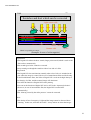
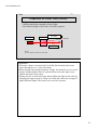
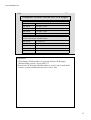
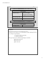
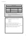
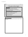
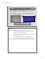
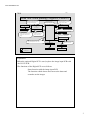
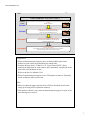
The point of this chapter
Key points
• Study the specifications of the machine.
Processing capacity
Main options
Spec of PC
Upon completion of the lesson, you will be able to:
*Understand what you can do with the machine and explain it to users.
*Understand processable media and format and explain it to users.
*Understand the standard parts and options and explain it to users.
*Understand the spec of built-in PC.
How to proceed the training
Explain, using the Training materials.
Refer to the “Specifications” manual for details.
2
www.minilablaser.com
31D_1
1010
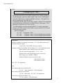
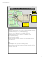
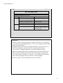
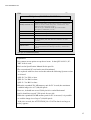
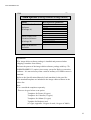
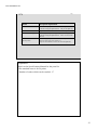
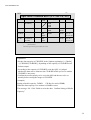
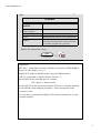
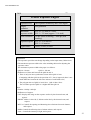
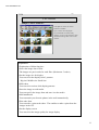
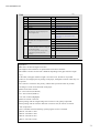
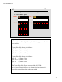
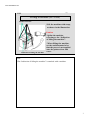
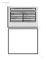
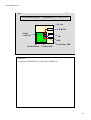
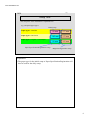
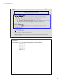
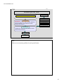
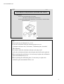
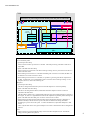
Concept (QSS-3101)
Full digital mini-lab system which outputs from scanning image to
the photographic paper by digital signal. This is the second digital
mini-lab with the laser engine installed at Noritsu. (The QSS-30 is
the first digital mini-lab with laser.)
Comparing with the QSS-30, the laser engine of QSS-31 has the high
processing speed ,and which is available for the wider paper. This
machine is responsive to a lot of needs.
“SI-2600 which is similar with the QSS-28” is used for the Input
section, LP-2200 is used for the Printer section and PP-1223 is used
for the Processor section.
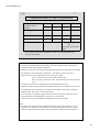
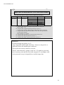
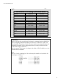
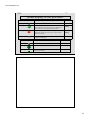
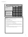
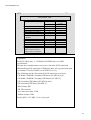
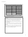
QSS-3101Digital :
127 x 89 2,369 prints / hour
127 x 89
552 prints / hour (3 slots, Digital camera/media)
127 x 89
912 prints / hour (5 slots, Digital camera/media)
Explanation
•Printing condition for making 2,369 prints (127 x 89) (With Index print,
Without Panorama print)
6-frame PJP 135F-24EX 24-frame exposed
•Printing condition for making 552/912 prints (127 x 89) (With Index print)
digital camera with 2,500,000 pixels (fine mode)
24-frame exposed high quality 1,712 x 1368
Without Index print, With digital camera correction
JPEG image size: 490KB to 560KB
When the Digital camera correction is ON:
432 prints/h (3 slots)
625 prints/h (5 slots)
•305 x 457 282 prints/hour
Note
•Processing capacity of QSS-2801/02
89 x 127 1901 prints/hour 2,598 prints/hour
•Processing capacity of QSS-2901
127 x 89 1480 prints 305 x 457 192 prints/hour
•Processing capacity of Frontier 370
127 x 89 approx. 1,550 prints/hour
3
www.minilablaser.com
31D_1
1020
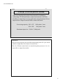
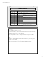
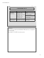
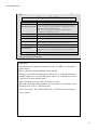
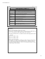
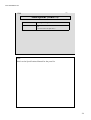
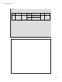
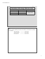
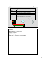
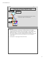
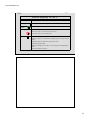
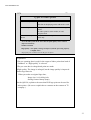
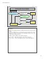
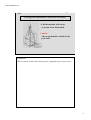
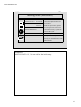
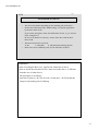
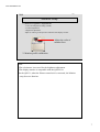
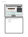
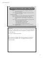
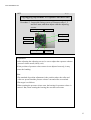
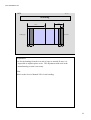
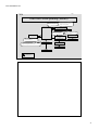
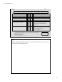
Concept (Network printer system)
Only receiving the print orders from network is available by
connecting LP-2200 and Printer control unit instead of SI-2600.
Possible to output from various application using the Printer Driver.
Impossible to output from the Printer control unit itself.
Processing capacity: 102 x 152 1,400 prints / hour
254 x 203
600 prints / hour
Maximum input size: 5,000 x 7,400 pixels
Explanation
•The processing capacity may be different depending on the PC spec which
sends the image data or the status of network line.
•The role of Printer control unit is to control the printer processor. So, it is
impossible to output from media.
4
www.minilablaser.com
31D_1
1060
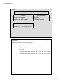
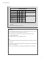
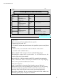
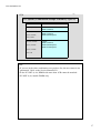
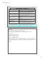
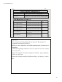
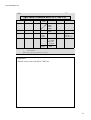
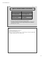
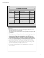
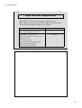
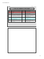
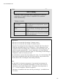
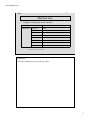
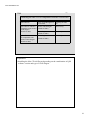
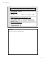
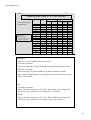
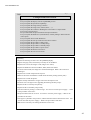
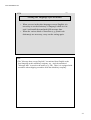
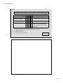
Types of QSS-3101
Name
QSS-3101Digital
QSS-3101SM Digital
Specification
Standard
SM specification
Name
QSS-3101 Network printer system
Explanation
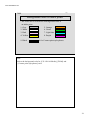
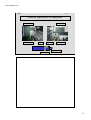
•There are two types of display monitors.
Northern hemisphere model and Southern hemisphere model
The specification of cathode-ray tube is different.
(The winding direction of coil for cathode ray tube is
reversed.)
* Northern hemisphere model: CDT-17102-3B (I074121-00)
* Southern hemisphere model: CDT-17102-2B (I074120-00)
5
www.minilablaser.com
31D_1
1090
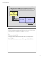
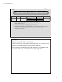
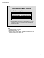
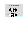
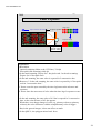
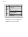
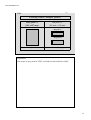
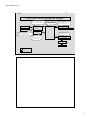
Name of QSS-3101 system
Input section
Output section
Digital printer
Paper processor
QSS-3101Digital
SI-2600
LP-2200
PP-1223
QSS-3101 network
printer system
Printer control
unit
LP-2200
PP-1223
Note
•SI-2600
Scanner&Image processor
Scanning ability
135F 2,600 frames / hour
•PP-1223
Paper processor
Paper advance speed: 2,300 mm / min
•LP-2200
Laser printer
Repeat print ability
3R (89x127) 2,200 prints /hour
6
www.minilablaser.com
31D_1
1100
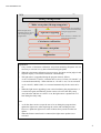
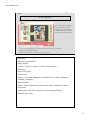
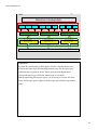
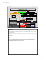
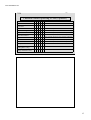
What can you do in the QSS-31?
Positive film
135 roll / mount
IX240 roll/ mount
120
Transparency
FB scanner
Negative film
135 (F/H/P/HD)
IX240 120 110
Print
Networking ability
File sharing
Mail function
Receiving the digital
media by CT-1
Printer Driver
Index Print
Output
Label index print
WB print
ID print
Package print
Post card
Calendar
Multi print
Letter print
Business card
Contact Print Style
Photos
B/W film
135 120
Digital camera
PC card
Smart media
Compact flash
Memory stick
SD card MMC
Micro drive
Storage media
FD, CD-ROM, HD
CD-R/RW, MO, ZIP, DVD-RAM, UDA
Output
Writing the image data
HD, FD, MO
ZIP, CD-R, CD-RW,
DVD-RAM
Memory stick
SD card MMC UDA
Micro drive
Explanation
•The image can be stored to one CD until the capacity of media is full. (So,
the number of negatives to be stored is not decided.)
(However, up to 5 orders can be seen with the CD-Viewer.)
•[CD-R writing device] can be selected as an OUTPUT media.
•DCP cannot be connected.
•EZ-mall cannot be installed.
•Memory stick, SD card, MMC and Micro drive are available with Five
slots card reader.
Note
•Standard: Black letter, Function of options: Red letter
•When the Printer control unit is connected, Printing is possible only from
the Printer control unit.
7
www.minilablaser.com
31D_1
1110
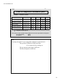
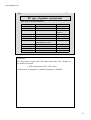
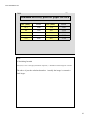
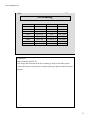
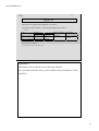
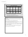
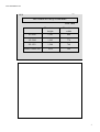
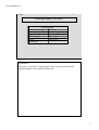
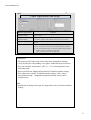
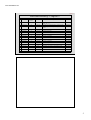
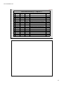
Usable media 1
x = possible
Types of
media
Input
Output
Additional
writing
x
x
FD
x
CD-ROM
x
CD-R
x
x
CD-RW
x
x
MO
x
x
Note
Standard equipment
CD-ROM (standard) or CD-R/RW (option) is
necessary.
The CD-R/RW drive (option) is necessary.
x
The MO drive (option) is necessary.
ZIP
x
x
x
The ZIP drive (option) is necessary.
DVD-RAM
x
x
x
The DVD-RAM drive (option) is necessary.
DVD-ROM
x
DVD-R
x
DVD-RW
Reflective
x
The flatbed scanner (option or procured parts
at customer’s site) is necessary.
*Explain the spec of each drive, etc. separately.
Explanation
•It is possible to process by CT-1.
•12cm CD’s and 8cm CD’s are supported. Business card CD’s and other
uniquely shaped CD’s are also supported.
•It is now possible to write in multiple sessions. (except CD-R/RW)
Note
•In the 31, when the Printer control unit is connected, ‘processing from
media’ is not available.
•The media capacity of CD is different depending on a maker.
8
www.minilablaser.com
31D_1
1120
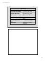
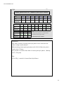
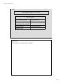
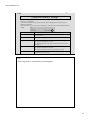
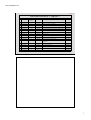
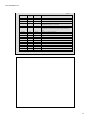
Usable media 2
Types of media
Input
Output
Additional
writing
Compact flash (Type I)
x
x
x
Smart media
x
x
x
PC card
x
x
x
Memory stick
x
x
x
SD card
x
x
x
Compact flash
(Type II)
x
x
x
MMC
(Multi media card)
x
x
x
Micro drive
x
x
x
Note
The PC card reader (option) or five
slots card reader (option) is necessary.
The five slots card reader (option) is
necessary.
x = possible
*Explain the spec of each drive, etc. separately.
Explanation
•As for the digital camera media, there are the media with security. Some of
them cannot process the copyright protected data.
•Even if the media is with security, it can process the data except the
copyright protected data.
•It is now possible to write in multiple sessions.
Note
•The copyright protected data is the encrypted data, and it cannot be created
and edited.
•In the QSS-31, when the Printer control unit is connected, ‘processing from
media’ is not available.
•Follow the attached Operator’s Manual for handling the PC card adapter.
9
www.minilablaser.com
31D_1
1130
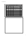
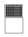
Processable Format
Image format
Input
Exif 1.0 (Thumb nail can be used in distinction from JPEG.)
JPEG (includes Progressive JPEG, CMYK Format)
FlashPix
Bitmap (non-compressed)
PSD (includes Photo Shop Document, CMYK Format)
PCD (Photo CD)
PCX, DCX (Paint Brush Format)
TGA (Targa)
TIFF (RGB non-compressed)
Output JPEG (except Progressive JPEG, CMYK Format)
FlashPix
Bitmap (non-compressed)
TIFF (RGB non-compressed)
Explanation
•JPEG 2000 is not available.
•As for the input image format, in case of RGB, 8-bit gradation only is
available.
16-bit gradation or gray scale is not available.
•Media (Windows format) only is available.
10
www.minilablaser.com
31D_1
1140
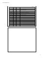
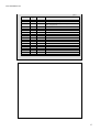
DPOF and Exif
Functions supported by QSS
Format
Contents of data
Function in the QSS side
DPOF
Date, Title, Image file name,
Frame No., Comment, Image title
Front print
Setting for the number of prints
Number of prints
Cropping of the image
Print
Date
Front print
Exif
Name of image input device maker Distinguish between the data
taken by the digital camera and
other image data.
Explanation
• If there is name of image input device maker (Exif data), it is recognized
as the image data from digital camera. If not, it is recognized as the image
data from normal media.
• If [Digital image auto correction (Digital camera)] is not used, remove a
check for [Image file selection] screen or [Operator Selections] ->
[Corrections] -> [Digital image auto correction (Digital camera)].
• When saving image data taken by digital camera to normal media in the
QSS, the name of image input device maker (Exif data) is overwritten
from ‘maker name of camera’ to ‘Noritsu’. This disables [Digital image
auto correction (Digital camera)] effective when reprinting.
• Refer to Chapter 3 [Front print] for the date of Exif data.
11
www.minilablaser.com
31D_1
1150
Processable DVD
Processable Format Capacity
DVD-RAM
(Input/Output)
Single side 2.6G
Double side 5.2G
(PC-NRT-3, 3A, 4, 4A)
Single side 4.7G
Double side 9.4G
(PC-NRT-4, 4A)
DVD-ROM (Input) Single side 4.7G
DVD-R (Input)
(PC-NRT-3, 3A, 4, 4A)
Format
TYPE1
(Cartridge-type, Impossible
to remove the disk)
TYPE2
(Cartridge-type, Possible to
remove the disk)
Disk-type
(“Play” only)
Explanation
•If you remove the disk from DVD-RAM TYPE2 and use it, it is impossible
to write the data.
•In the QSS-31, PC-NRT-3(3A) does not exist.
12
www.minilablaser.com
31D_1
1160
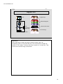
Main options (Film carriers)
Types of
masks
Film type
135/240
AFC
Negative/Positive/Black&
White/(Roll)
Sepia/Black&White
(orange base)
135F, H, P,
HD
IX240
Minimum number of frames:2-frame
120AFC
Negative/Positive/Black&
White
Sepia/Black&White
(orange base)
6x4.5, 6x6,
6x7, 6x8,
6x9
Minimum advance length:43 mm
(6 x 4.5 1 frame)
110AFC
Negative
110
Minimum number of frames:3-frame
135F, 135H,
IX240
IX240: Positive only can be processed.
Length of mount
50 mm x 50 mm
Thickness: 1.0 mm – 3.2 mm
Glass mount is not available.
135/240MMC Negative/Positive/Black&
White
Sepia/Black&White
135/240AMC (orange base)
Size
Note
Show each AFC.
Explanation
•Refer to the Specification Manual for the part No.
•Explain, showing each AFC.
•135/240AFC became an option because it is possible to process only from
media.
•1-frame (135F) is not available with 135/240AFC and 135AFC.
(Available with 135MMC/AMC.)
•With 135MMC/AMC, Negative/Positive/Black&White/Sepia/
Black&White (orange base) are processable. As for IX240, however, the
positive film only is processable.
•In the QSS-28, as for the machine with ENV attached, when using the
AMC, AMC kit for ENV is necessary for machines in the early shipping.
Refer to the Specification Manual for details.
•Film insert direction
In the 3rd modification, insert the film from the rear end. In the 4th
modification, however, the rewinding part is improved. So, the inserting
from front end became possible, but tell a trainee the cautions when
inserting a film from front end, same as the conventional machines.
The sticker of attention “Be sure to insert the front end of film without any
remaining splicing tape or its glue” is attached.
13
www.minilablaser.com
31D_1
1180
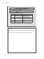
Main options (Around Film carriers)
Name
Description/Explanation
IX240 auto supplier
Unit to supply an IX240 cartridge automatically
Including the IX240 auto supplier PCB
Film set feeder
Used to supply two of 135 films automatically
Rail unit
Unit via which the IX240 auto supplier and the film set feeder are attached
135/240 AFC modification kit
Kit for modifying a 135/240AFC when the IX240 auto suppliers is
attached to the machine.
Long roll feeder
Used to supply 135 film automatically (135F 24 prints, approximately 100
rolls)
In the QSS-2801, when attaching it, the expand memory unit (Z018855-01)
should be attached with it.
Sleever (6 frames specification)
Used to cut the scanned film and insert it into a film sheet automatically
In the QSS-2801, When attaching it, the expand memory unit (Z018855-01)
should be attached with it.
Sleever (4 frames specification)
Expanded memory unit
Used to speed-up the printing by expanding the memory onto the
image processing PCB (Up to the images with 60 frames can be
stored.) This is an option only for the QSS-2801. (This is
equipped as a standard equipment for the QSS-2802.)
When attaching the LRF and ENV, attach them as a set.
Explanation
•Refer to the Specifications Manual for the parts No.
14
www.minilablaser.com
31D_1
1200
PC Options (PC-NRT-4, PC-NRT-4A)
Name
Description/Explanation
DIMM(256MB PC133)
DIMM(512MB PC133)
Extended memory unit for Personal Computer, for the stable use of the
Photoshop, and for enabling to read the image size of up to 37,000,000 pixels.
(However, it should not exceed 5,000 pixels in vertical/horizontal. And, it
should not exceed 7,500 pixels for one side.)
There are two types - 256MB and 512MB-, up to 1GB is available.
(In the QSS-28, 512MB memory is not set.)
ZIP drive unit
Unit to save/read the image data to a ZIP
MO drive unit
Unit to save/read the image data to a MO
DVD-RAM drive unit
Unit to save/read the image data to a DVD-RAM
Five slots card reader
Unit to save/read the image data from PC card, Compact flash, Smart media,
SD card and Memory stick, MMC, Micro drive, xD-Picture card (USB
connection)
CD-RW drive unit
Used to save/read the image data to a CD-R/RW
Flatbed scanner
Used to read the reflective (e.g. photograph) as image data
In the QSS-29, used also when calibrating the uniformity. (manufactured by
UMAX)
LAN board
Used to connect the QSS with network
*The spec, etc is mentioned separately.
Explanation
•You cannot use an option except above items. In the QSS-28/29/31, PCNRT-4/4A is used.
•Refer to the Specification Manual for the part No.
•The conventional PC card reader was discontinued.
It is replaced with five slots card reader when the following System version
is released.
QSS-28: Ver.F001 or later
QSS-29: Ver.D001 or later
QSS-31: Ver.B001 or later
•When the expanded 256 MB memory unit for PC is used, the maximum
readable image size is 37,000,000 pixels.
However, it should not exceed 5,000 pixels in vertical/horizontal.
And, it should not exceed 7,500 pixels for one side.
When the expanded 256 MB memory unit for PC is not used, it is possible
to read the image size of up to 7,600,000 pixels.
If the size exceeds, the ATTENTION [No. 1516 The data is too large to
write.] appears.
15
www.minilablaser.com
31D_1
1201
PC Options (PC-NRT-5)
Name
Description/Explanation
RIMM(128MB PC800)
RIMM(256MB PC800)
Extended memory unit for Personal Computer, for the stable use of the
Photoshop, and for enabling to read the image size of up to 37,000,000 pixels.
(However, it should not exceed 5,000 pixels in vertical/horizontal. And, it
should not exceed 7,500 pixels for one side.)
There are two types - 256MB and 512MB-, up to 1GB is available.
(In the QSS-28, 512MB memory is not set.)
ZIP drive unit
Unit to save/read the image data to a ZIP
MO drive unit
Unit to save/read the image data to a MO
DVD-RAM drive unit
Unit to save/read the image data to a DVD-RAM
Five slots card reader
Unit to save/read the image data from PC card, Compact flash, Smart media,
SD card, Memory stick, MMC and Micro drive (USB connection)
CD-RW drive unit
Used to save/read the image data to a CD-R/RW
Flatbed scanner
Used to read the reflective (e.g. photograph) as image data
In the QSS-29, used also when calibrating the uniformity. (manufactured by
UMAX)
LAN board
Used to connect the QSS with network
*The spec, etc is mentioned separately.
Explanation
•You cannot use an option except above items. PC-NRT-5 is used in the
QSS-28/29/31.
•Refer to the Specification Manual for the part No.
•When the expanded 256 MB memory unit for PC is used, the maximum
readable image size is 37,000,000 pixels. However, it should not exceed
5,000 pixels in vertical/horizontal.
And, it should not exceed 7,500 pixels for one side.
When the expanded memory unit for PC is not used, it is possible to read
the image size of up to 7,600,000 pixels.
If the size exceeds, the ATTENTION [No. 1516 The data is too large to
write.] appears.
16
www.minilablaser.com
31D_1
1230
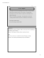
PC options (Combination example of memory: QSS-31)
Installed DIMM
PC-NRT-4, 4A
Standard (256MB)
Available
DIMM1 (standard)
Standard (256MB)
+
Option (256MB)
Total:512MB
Available
DIMM1 (standard)
DIMM2 (256MB option)
Standard (256MB)
+
Option (256MB)
+
Option (512MB)
Available
DIMM1 (standard)
DIMM2 (256MB option)
DIMM3 (512MB option)
Total:1GB
Note
• If you use in the other combination except above list, the movement is not
guaranteed. Refer to the Service Manual 6521.
• In the PC-NRT-4, 4A, DIMM with more than 1GB cannot be attached.
• PC-NRT-4 (A) installs DIMM only.
17
www.minilablaser.com
31D_1
1230
Installed RIMM
PC-NRT-5
Standard (256MB)
Available
RIMM 1 (128MB standard)
RIMM 2 (128MB standard)
Install a dummy module to RIMM 3 (standard)
Install a dummy module to RIMM 4 (standard)
Standard (256MB)
+
Option (256MB)
Total: 512MB
Available
RIMM 1 (128MB standard)
RIMM 2 (128MB standard)
RIMM 3 (128MB option)
RIMM 4 (128MB option)
Option (1GB)
Total: 1GB
Available
RIMM 1 (256MB option)
RIMM 2 (256MB option)
RIMM 3 (256MB option)
RIMM 4 (256MB option)
Explanation
• If you use in the other combination except above list, the movement is not
guaranteed. Refer to the Service Manual 6521.
• PC-NRT-5 installs RIMM.
• In the PC-NRT-5, there is no setting for RIMM with 1GB or more.
18
www.minilablaser.com
31D_1
1240
Main options (Package contents of image edition)
Name
Card/Calendar Creation
Software
(Package-A)
Description/Explanation
Calendars
Greeting Cards (Poster card prints)
Card Prints
Business Cards
Frame Prints
Letter printing
Multi-Frame Print
Creation Software
(Package-B)
Multi-Frame Prints
Album Prints
Package Prints
Contact Print Style Photos
ID Photos
Red Eye Removal
Software
Red eye removal function
Explanation
•The image edition software package is installed and protected when
shipping a machine from factory.
•Release the protect of the image edition software package with key CD.
•DIMM256MBPC133 (option) is necessary except for Red-eye correction
software. It is not necessary when a total of memory of 512MB or more is
attached.
•Refer to the Specifications Manual of each machine for the parts No.
•The standard templates are included in the image edition software in the
above list.
Note
•You can add the templates separately.
There are 4 types below as an option.
Templates for Frame (29 types)
Templates for Calendar (21 types)
Templates for Album (21 types)
Template for Business card
(67 types, appendix: 14 types of cards, 16 types of Multi)
19
www.minilablaser.com
31D_1
1250
Main options (Others 1)
Name
Description/Explanation
Digital ICE
Used to remove scratches, etc. from image in negative or positive which is scanned by the built-in
scanner. (In the QSS-28/31, it is necessary to attach the D-ICE PCB. In the QSS-29/30, it is already
attached, so it is necessary to install the software and put the sticker of D-ICE mark.)
Noritsu CD-R Engine
(Windows/Mac)
Used for saving the Viewer software for Macintosh to CD/RW.
Also necessary when saving the images to optional QSS CD.
QSS CD
(TYPE A)
CD-R to which the viewer software (Deluxe Viewer) has been written. CD-R label is printed.
(100 CD-Rs) (Common among the QSS-28/29/30/31)
QSS CD
(TYPE B)
CD-R to which the viewer software (Deluxe Viewer) has been written. CD-R label is not printed.
(100 CD-Rs) (Common among the QSS-28/29/30/31)
Bar code reader
Used to read the order sheet of the consumer terminal CT-1.
(Common among the QSS-28/29/30/31)
Image rotation
booster
Possible to shorten the time for displaying the image when rotating the image slightly.
Image rotation booster itself is common among the QSS-29, 30, 31, but the option No. is different
because the attaching part is different.
Package print format
creation software
Used for making templates for package print as you like.
USB expansion code
Used when there is not enough USB ports for peripheral devices to be connected to QSS. (Standard:
2 USB ports, Option: 2 USB ports are added.)
(Common between the QSS-28 and 31. Only for the QSS-29 and 30 each.)
Explanation
• Refer to the Specification Manual for details.
• The part No. of [USB expansion cable] is different between QSS-3001 and
3011. (The connector on the mother board side is different.)
• The image rotation booster is available when the following System version
is released.
QSS-29: Ver.E001 or later
QSS-30: Ver.E001 or later
QSS-31: Ver.C001 or later
• In the QSS-31 (SI-2600), the attaching procedure of image rotation booster
kit is different depending on the manufactured No. Therefore, there are
two kinds of image rotation kit. Refer to the Installation Manual of Image
rotation booster kit for details.
20
www.minilablaser.com
31D_1
1260
Main options (Others 2)
Name
Description
UDA unit
The device to be used for saving the Image data scanned from film.
The data of certain number of films is stored in the Hard disk.
Possible to make a print/output to storage media from the stored
image data. (Common among the QSS-28/29/31)
CD-R external writing system
Using the CD-R external writing system made by Rimage, write the
image data to CD-R at the same time of printing, and make a label
print. (Common among the QSS-28/29/31)
CD-R writing kit for external
PC
Required kit for the connection of CD-R external writing system
(Rimage)
This consists of PCB, cable and software. (Common among the
QSS-28/29/31)
CD-R external writing system
connecting kit
Using the CD-R drive of external PC prepared by a customer, write
the image data to CD-R at the same time of printing.
(Common among the QSS-28/29/31)
QSS Printer Driver
Used as Driver software to print the image data with QSS, which is
saved in the PC connected with QSS. (Install this software in the
external PC.) (Common among the QSS-28/29/30/31)
Refer to the Training material
[CD-R External Writing System].
Refer to the Training
material [UDA unit].
Refer to the Training material
[QSS Printer Driver].
Explanation
•Refer to the Specification Manual for details.
•The UDA unit is available when the following System version
is released.
QSS-28: Ver.F002 or later
QSS-29: Ver.E001 or later
QSS-31: Ver.B002 or later
•Each component of part for [CD-R writing kit for external PC] and [CD-R
external writing system connecting kit] is different between QSS-28/31 and
QSS-29.
21
www.minilablaser.com
31D_1
1270
Main options (Others 3)
Name
Description/Explanation
CVP
Only for QSS-28/29/30/31 each
Compact ribbon cassette
Common among the QSS-28/29/30/31
Pricing unit
Used to calculate prices and issue statements automatically
(Common between QSS-28 and 31. Only for the QSS-29 and 30
each.)
Monitor hood
Common among the QSS-28/29/30/31
Storage cabinet
Cabinet in which an auto film carrier, an IX240 auto supplier and a
film set feeder are stored. (Only for each machine. This is not set
for the QSS-30.)
Film cleaner kit
Common among the QSS-28/29/30/31
Negative cleaner
There are 3 types of specifications.
(Only for each machine. This is not set for the QSS-30.)
100V, 120V, 220V-240V
Note
•Refer to the Specifications Manual for the parts No.
22
www.minilablaser.com
31D_1
1270
Name
Description/Explanation
Hour meter
Meter which displays the accumulated working time
(Common among the QSS-28/29/31. Only for the QSS-30)
Non-resettable counter
(Only for each machine. This is not set for the QSS-30.)
One-touch dark bag
Used when paper is repacked to paper magazine (Frame type)
(Common among the QSS-28/29/31. This is not set for the
QSS-30.)
Sorter modification kit
(for 82 prints)
Kit for modifying the print sorter unit to that for 82 prints in one order.
Number of orders which can be stocked: 14
(Only for each machine. This is not set for the QSS-30.)
Explanation
•Refer to the Specifications Manual for the parts No.
•The standard sorter is for 50 prints.
Number of orders which can be stocked: 17
23
www.minilablaser.com
31D_1
1280
Main options (Others 4)
Name
Description/Explanation
Side table
Table which is used to extend the table width to the left or
right
(Common between the QSS-28/31)
Note
•Refer to the Specifications Manual for the parts No.
24
www.minilablaser.com
31D_1
1310
Main options (magazines)
Standard magazine
Compatible between Normal and Kodak specification. (Carry out
the unit replacement only as it is already adjusted.)
QL magazine
For QL paper (Carry out the unit replacement only as it is already
adjusted.) The core unit is different from the standard magazine.
Width Regulation Guide Kit (1)
Name
Magazines
Paper width
Width Regulation Guide Kit (1)
(For standard magazine)
Roller guide (1)
Width Regulation Guide (movable length:1 mm)
82.5 to 178 mm
Width Regulation Guide Kit (2)
(For standard magazine)
Roller guide (2)
Width Regulation Guide (movable length:1 mm)
203 to 254 mm
Width Regulation Guide Kit (3)
(For standard magazine)
Roller guide (3)
Width Regulation Guide (movable length:2 mm)
279 to 305 mm
Width Regulation Guide Kit (4)
(For QL magazine)
Roller guide (1)
Width Regulation Guide (movable length:1 mm)
For QL paper only
89 to 165 mm
Width Regulation Guide Kit (5)
(For QL magazine)
Roller guide (2)
Width Regulation Guide (movable length:1 mm)
For QL paper only
203 to 254 mm
Explanation
•Refer to the Specification Manual for the parts No. The magazine is
compatible between QSS-29 and 31.
•When you order a magazine, each width regulation guide is attached to all
magazines.
The Width Regulating Guide Kit is set as an option in case that a customer
loses or breaks it.
•Replace the magazine assembly (magazine main body + paper regulating
plate) as a whole unit.
•Replace the Spindle assembly (spindle main body + reel plate) as a whole
unit.
25
www.minilablaser.com
31D_1
1320
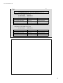
Compatible table of unit for processor
Compatibility of unit
among the type of
machine
QSS-2801 QSS-2802
QSS-2901 QSS-3101
PP-1216
PP-1216
PP-1223
PP-1223
Processing solution
A
B
C
B
Dryer rack (upper)
D
D
E
E
Dryer rack (lower)
F
F
F
F
Note
Processing in 3-lane
Processing in double-lane
and
Processing of wide-width
paper
*If the unit has same letter with another one, there is a compatibility between
two types of machines.
Explanation
• The above compatible table is mentioned in the case of Standard type, and the above
compatible table will be applied to SM also.
• Differences of processing racks between QSS-2801 and 2802 [Comparison of A and B]
The number of racks and length are different. (The shape of roller is the same.)
Shape of roller: Taper-shaped roller which center part is thick
This is used for both of center roller and side roller.
But, you cannot check that it is the taper-shaped center roller by naked
eyes.
• The processing racks are compatible between the QSS-2802 and 3101.
• Differences of processing racks between QSS-2801 and 2901 [Comparison of A and C]
The number of racks and length are the same, but the shape of side roller is different.
Shape of roller: Flat roller is used for Side roller.
• As for the dryer rack (upper), QSS-28 does not have a lane selection function for the
wide-width paper, but the QSS-2901 and 3101 have the function.
From this cause, the unit is different depending on the type of machine.
Note
• The shape of processing roller is different depending on the type of machine. And, it
depends on the difference of transportation “3-line processing and 2-line processing”
(balance of pressure advance power), matching with processing solution and the cost.
26
www.minilablaser.com
31D_1
1330
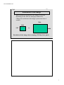
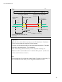
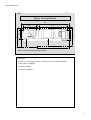
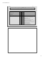
Explanation of the system (Connection)
SI-2600
OR
Printer control unit
Power supply cable (200V)
LVDS cable
LP-2200
PP-1223
Optical fiber cable (ARCNET)
Power supply: IP2W 200V
Explanation
•When the standard type cable is used, the interval between SI-2600, Printer
control unit and LP-2200&PP-1223 is approx. 5 m (max.).
Note
•The reason of using LVDS
Comparing with the IEEE1394 used in the QSS-28, the image transfer
speed is higher.
In the QSS-28, the connector section of DLP engine PCB is IEEE1394.
27
www.minilablaser.com
31D_1
1340
Table of compatible consumable parts
Scanner + Printer section
Name
Part No.
Scanner lamp
I061219-00
Air filters (scanner)
A056917-01
MLVA lamp
I061219-00
Air filters (MLVA)
A056917-01
Ribbon cassettes
H086035-01
QSS-31 QSS-29
QSS-28
QSS-27
= compatible with the QSS-31
The connector code of scanner lamp is different between the QSS-28/29/31 and QSS-27.
*For QSS-28/29/31:
White
*For QSS-27
:
Black
Note
•The lamp for QSS-27 is not compatible with that for QSS-28/29/31.
- The position of filament is different a little.
(You cannot tell it by looking at.)
- The gas amount in the lamp is different.
- The heat dissipation is different.
28
www.minilablaser.com
31D_1
1350
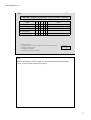
Print sizes
Processable paper width
82.5 mm to 305.0 mm
Paper advance length
82.5 mm to 457.0 mm
Maximum print size
305.0 mm to 457.0 mm
Usable paper
Maximum diameter of
paper
Usable paper
250 mm (180 m length)
Thin paper (0.2 mm) is
supported.
29
www.minilablaser.com
31D_1
1360
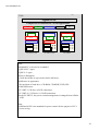
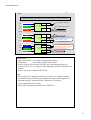
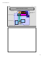
Types of PC
Comparison of standard PCs in the appearance
DVD
ZIP
CD- ROM (R/RW)
MO
FD
ZIP
CD-ROM (R/RW)
DVD
DVD
ZIP
ZIP
CD-ROM (R/RW)
DVD
CD-ROM (R/RW)
MO
MO
MO
FD
FD
FD
PC-NRT-3 (3A)
PC-NRT-4 (4A)
PC-NRT-5
Note
•Standard PC to be used as a standard
QSS-28/29: 3 types
QSS-31: 2 types
•How to distinguish
Check the sticker of type on the slot for MO drive.
•Difference in appearance
Slot positions of each drive -CD-ROM, CD-R/RW, DVD, ZIP-.
•Other differences
PC-NRT-3: CD drive is SCSI connection.
PC-NRT-4, 5: CD drive is ATAPI connection.
•In the PC-NRT-5, the power control management is changed from APM to
ACPI.
Note
•APM and ACPI is the standard for power control for the purpose of PC’s
power saving.
30
www.minilablaser.com
31D_1
1380
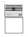
Specifications of personal computers (PC-NRT-4)
Spec table of standard PC
Product name
Specifications
CPU
Pentium III
1GHz
Mother board
CA64-BN
Memory
PC-NRT-M256
256MB PC133
3.5FDD
FD-235HF
2 modes
Hard disk
QML20400ASA-A
20GB
CD-ROM drive
CR-594J (existing model)
48x
ATAPI
CR-564B (discontinued model)
Video board
MILL G450 DUAL H. 32MB
Keyboard (Japanese)
FKB8724-501
Keyboard (English)
FKB8725-401
Mouse
Microsoft PS/2 mouse
OS
Windows 2000 professional
SGRAM
Dedicate version
Explanation
•It is impossible to replace the ATX mother board unit only itself.
•Replace the mother board unit as a whole set. (ATX mother board, CPU
and CPU cooler)
31
www.minilablaser.com
31D_1
1390
Specifications of personal computers (PC-NRT-4A)
Spec table of standard PC
Product name
Specifications
CPU
Pentium III
1GHz
Mother board
CA64-TN
Memory
PC-NRT-M256
256MB PC133
3.5FDD
FD-235HF
2 modes
Hard disk
6E040L0 (existing model)
40GB 7200rpm
6L040J2 (discontinued model)
CD-ROM drive
CR-594J (existing model)
48x
ATAPI
CR-594B (discontinued model)
Video board
MILL G450 DUALH 32MB
Keyboard (Japanese)
FKB8724-501
Keyboard (English)
FKB8725-401
Mouse
Microsoft PS/2 mouse
OS
Windows 2000 professional SP2.
SGRAM
Explanation
• It is impossible to replace the ATX mother board unit only itself.
• Replace the mother board unit as a whole set. (ATX mother board, CPU
and CPU cooler)
32
www.minilablaser.com
31D_1
1391
Specifications of personal computers (PC-NRT-5)
Spec table of standard PC
Product name
Specifications
CPU
Pentium IV
2GHz
Mother board
D850EMV2
Memory
PC-NRT-RIMM
256MB PC133
3.5FDD
FD-235HF
2 modes
Hard disk
6E040L0
40GB 7200rpm
CD-ROM drive
CR-594J
48x
Video board
MILL G450 DUALH 32MB
SGRAM
Keyboard (Japanese)
FKB8724-501
Keyboard (English)
FKB8725-401
Mouse
Microsoft PS/2 mouse
OS
Windows 2000 professional SP3.
ATAPI
Explanation
• It is impossible to replace the ATX mother board unit only itself.
• Replace the mother board unit as a whole set. (ATX mother board, CPU
and CPU cooler)
33
www.minilablaser.com
31D_1
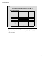
1430
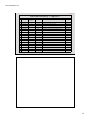
Spec table of media drive (PC-NRT-4, 4A)
Machine type
Maker
ZIP
250MB
100MB
IDE
(ATAPI)
PLEXTOR
CD-ROM
CD-R
CD-RW
650MB
700MB*1
IDE
(ATAPI)
Read: 40x
Write: 16x
Overwrite: 10x
PLEXTOR
CD-ROM
CD-R
CD-RW
Can be set
IDE
(ATAPI)
Read: 40x
Write: 40x
Overwrite: 12x
FUJITSU
Zip
Zip250
Iomega
PC-W4012TA
[PX-W2410TA]
[RW7200A]
[
Interface
SCSI-2
MCM3064SS
[MCE3064SS]
CD-R/RW
(PC-NRT4A)
Data capacity
640MB
540MB
230MB
128MB
MO
CD-R/RW
PX-W1610TA
(PC-NRT-4)
Types of
media
]: Discontinued No.
Both of old type and new type hard disks can be used.
Explanation
• Set the data capacity of CD-R/RW in the [Option registration] -> [Media]
-> [CD-ROM (CD-R/RW)], depending on the capacity of CD-R/RW used
for data output.
• According to the capacity of CD-R/RW set in the QSS, it is judged
whether the data can be written to the CD-R/RW which you set or another
CD-R/RW is necessary.
• Confirm the media capacity to be set in the QSS and the one to be set
actually before storing the image to CD-R/RW.
(example)
Setting of media capacity: 700MB
CD-R to be used (650MB)
When the data capacity to be written is 650MB or more
The message “No. 1546 Failed to write the data. Confirm Setting of Media
Capacity.”
34
www.minilablaser.com
31D_1
1430
Machine type
DVD
LF-D291NS
Maker
Panasonic
Types of
media
Data capacity
DVD-RAM
Single side 4.7, 2.6GB
Double-side 9.4, 5.2GB
DVD-ROM
DVD-R
Single side 4.7GB
Interface
SCSI-2
35
www.minilablaser.com
31D_1
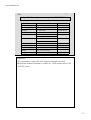
1431
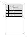
Spec table of media drive (PC-NRT-5)
Machine type
Maker
MO
MCM3064SS
FUJITSU
Zip
Zip250
Iomega
CD-R/RW
PX-W4012TA
DVD
LF-D291NS
[
Types of
media
Data capacity
Interface
640MB
540MB
230MB
128MB
SCSI-2
ZIP
250MB
100MB
IDE (ATAPI)
PLEXTOR
CD-ROM
CD-R
CD-RW
Can be set
IDE (ATAPI)
Panasonic
DVD-RAM
Single side
4.7, 2.6GB
Double side
9.4, 5.2GB
SCSI-2
DVD-ROM
DVD-R
Single side
4.7GB
Read: 40x
Write: 40x
Overwrite: 12x
]: Discontinued No.
Both of old type and new type hard disks can be used.
Explanation
• Details are the same with the PC-NRT-4A.
36
www.minilablaser.com
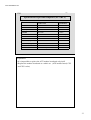
31D_1
1460
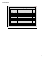
Spec table of peripherals (PC card reader)
Drive
Type
Maker
Types of media
Data capacity
Interface
Card reader
PCD-47B
Microtek
International
Smart media
2 to 128MB*1
SCSI-2
Compact flash
*2
PC card
*3
*1: compliant with Smart Media Physical Specifications Version 1.2
Drive Voltage: 3.3V, 5V
*2: compliant with Compact Flash Specification Version 1.4
No limit in the capacity. Type I only can be set. Type II (micro drive) cannot be set.
*3: compliant with PC Card Standard Release 8 PC Card ATA Specification
No limit in the capacity.
Explanation
• Common among PC-NRT-3, 3A, 4 and 4A.
The PC card reader is compatible with the QSS-3001/3011. However, the
part No. is different because the attached part is different.
• As for memory stick and SD card, when using the PC card adapter with
write-protected, it may be impossible to read the image data.
37
www.minilablaser.com
31D_1
1470
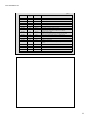
Spec table of media drives (Five slots card reader)
Five slots card reader [Common between QSS-3001 and 3011]
Drive
Type
Maker
Types of media
Data capacity
Interface
Five slots
card reader
PCD-50N
Microtek
International
Smart media
4 to 128MB*1
USB
Compact flash
*2
PC card
*3
SD card
8 to 128MB*4
Memory stick
8 to 128MB*5
MMC
4 to 64MB*6
*1: compliant with Smart Media Physical Specifications Version 1.2
Drive Voltage: 3.3V
*2: compliant with Compact Flash Specification Version 1.4
No limit in the capacity. Both of Type I and II (micro drive) can be set.
*3: compliant with PC Card Standard Release 8 PC Card ATA Specification
No limit in the capacity.
Drive voltage: 5V, 3.3V/5V
*4: compliant with SD Memory Card Specification Version 1.0
*5: compliant with MS Specification Version 1.2
*6: compliant with MMC System Specification Version 2.1
Explanation
• Common among the QSS-28, 29, 31.
Also compatible with the QSS-3001/3011. However, the part No. is
different because the attached part is different.
• The media with security cannot be accessed.
• The PC card which drive voltage is only for 3.3V cannot be processed.
• As for memory stick and SD card, when using the PC card adapter with
write-protected, it may be impossible to read the image data.
38
www.minilablaser.com
31D_1
1480
Spec of flatbed scanner (Astra3400)
Type
Astra3400
Maker
UMAX
Color scanning method
Color CCD (Single Pass)
Maximum area of scanning
216 x 297 mm (8.5 x 11.7-inch)
Optical resolution
600 x 1200 dpi
Maximum resolution
9600 x 9600 dpi
Interface
USB
•This type is discontinued and replaced with Astra4400.
•AC adapters which are necessary for the flatbed scanner are divided into
7 types because the shape of power supply and plug socket is different
depending on the country.
Note
• Common among QSS-28/29/30/31.
• The maximum input size: A4
• When you order the flatbed scanner, check the type of power supply and
the shape of plug socket for country each.
39
www.minilablaser.com
31D_1
1490
Spec of flatbed scanner (Astra4400)
Spec of flatbed scanner (option)
Type
Astra4400
Maker
UMAX
Color scanning method
Color CCD (Single Pass)
Maximum area of scanning
216 x 297 mm (8.5 x 11.7-inch)
Optical resolution
1200 x 2400 dpi
Maximum resolution
9600 x 9600 dpi
Interface
USB
•AC adapters which are necessary for the flatbed scanner are divided into
7 types because the shape of power supply and plug socket is different
depending on the country.
Note
• Common among QSS-28/29/30/31.
• The maximum input size: A4
• When you order the flatbed scanner, check the type of power supply and
the shape of plug socket for country each.
40
www.minilablaser.com
31D_1
1500
PC spec of printer control unit
Spec table of PC (PC-NRT-PS1)
Product name
Specifications
CPU
Pentium4
Mother board
NT70SC
1.6GHz
Memory
MC-4R256FKE6D-845
256MB
PC800 x 4
3.5FDD
FD-235HF
2 modes
Hard disk
6L049J2
40GB 7200rpm
CD-ROM drive
FX-54
54x ATAPI
Video board
MILL G450
/DDR32MB/DH/AGP/OEM
32MB AGP
Keyboard (Japanese)
FKB8724-501
Keyboard (English)
FKB8725-401
Mouse
ECM-S500Z
OS
Windows 2000 Professional SP2.
Explanation
•It is impossible to replace the ATX mother board only itself. Replace as
the mother board unit.
(ATX mother board, CPU, CPU cooler)
•1GB memory is equipped as a standard equipment. (RIMM)
41
www.minilablaser.com
31D_1
1510
Procured parts at customer’s site
It is possible to connect the image scanner (on the market) with the QSS for Print to Print.
It is necessary that a customer prepare the device to be used separately.
The followings are the products specified by Noritsu.
Name
Product name
Maker
Connection
Description
Image scanner
Prefection2450
EPSON
USB
Used for “Print to Print”. Up to A4 size
Image scanner
Perfection3200
EPSON
USB
Used for “Print to Print”. Up to A4 size
Image scanner
GT-10000+
EPSON
SCSI
Used for “Print to Print”. Up to A3 size
Necessary options (part No.: I090199)
Color input target + Floppy
Used for the calibration of flatbed scanner.
Explanation
• Refer to the operating instructions attached to each device for handling the
peripherals and connecting method.
• As for some problems concerning the image scanner, contact each maker.
• The necessary option is not sold on the market, so it is necessary to
purchase it as an option.
Note
• In the QSS-29, GT-9800F will be available in software version E002.
42
www.minilablaser.com
31D_1
1900
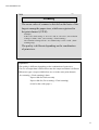
Comprehension check
[Specifications]
*Do you understand available print sizes?
*Do you understand processable media types and format?
*Can you explain which option is necessary depending on the customer’s
request?
*Can you change the magazine width?
*Can you explain when you are asked about the PC spec?
*Can you explain the differences among PC-NRT-3 (3A), PC-NRT-4(4A) and PCNRT-5?
*Do you understand the processable films?
*Can you explain the differences between card reader and five slot card
reader?
*Do you understand about the media capacity setting of CD-R/RW?
*Do you understand the processable image sizes?
[Question]
*What kind of index print is available?
*What kind of index print is there as a standard?
*In which print, is the optional software necessary to output?
*What is the processable format?
*What option is necessary for making the Contact print style photos?
*What option is necessary for letter printing?
*When using the paper with 254 mm width, which guide should be attached
to a magazine?
*When using the paper with 305 mm width, which guide should be attached
to a magazine?
*What is the standard memory of PC? What is the maximum memory size
with an option?
*What MHz is used for the CPU?
*What GB of HDD is used?
*Is there a compatibility of HDD between PC-NRT-3, PC-NRT-4 and PCNRT-5?
*What is compatible among PC-NRT-3, PC-NRT-4 and PC-NRT-5?
*What setting is required for using a CD-R of 700MB?
*What is the kind of media which is available for additional writing?
43
www.minilablaser.com
31D_2
Chapter 2
Outline of the system
1
www.minilablaser.com
31D_2
2000
The point of this chapter
Key points
* Explain the outline of the system for each machine.
Scanner, Exposure engine, Image size, Paper size, Digital-ICE, Paper advance
system
Upon completion of the lesson, you will be able to:
*Understand the specifications and structure of scanner.
*Understand the number of pixels for scanning and the number of resolution
for print.
*Understand the dust and scratches which can be processed with the Digital
ICE and its theory.
*Understand the paper advance way.
*Understand the structure of exposure engine and the function of each
section.
How to proceed the training
Explain the items referring to the training materials and using the actual
machine.
2
www.minilablaser.com
31D_2
2010
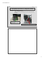
Scanner light source
Light source :
The halogen lamp of 30.5V and 370W is used for the light
source of film scanner.
(Voltage of connector part of lamp: 27.7V)
The lamp and socket are assembled in one, and the heat sink
is attached. There is no compatibility with the conventional
model. (The scanner lamp is common among the QSS28/29/31.)
Light source parts :
The reflector is not a consumable part, so it is unnecessary
to replace it.
The lens box is slit condenser type.
(The lens box is common among the QSS-28/29/31.)
Explanation
•The life of halogen lamp is approx. 900 hours.
•Explain not to operate with putting the negative sheet onto the lens box.
(This is different from the conventional machines.)
Putting the negative sheet onto the lens box causes the curl of film because
of the high temperature.
•The lens box is changed from a machine of the end of August, 2001 or later.
•As for the modified lens box, the lens is manufactured for increasing the
diffusivity of transmitted light.
3
www.minilablaser.com
31D_2
2020
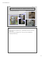
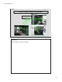
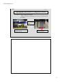
Structure of scanner unit
Negative/positive filter
Mirror
Halogen lamp
Lens box
Diffuser
Heat absorbing filter
Lens
Film carrier
Scanner lens
CCD
for detecting scratches
Mirror
CCD
for detecting RGB images
Note
•The scanner unit is common among the QSS-28/29/30/31.
4
www.minilablaser.com
31D_2
2030
Scanner
Image capture
method
Optical resolution (Main
or the CCD line)
Input one line image with line CCD.
Scan pitch (Sub scanning) Film is moved.
Scan RGB each with line CCD (5,000 pixels).
CCD
Others
ISL filter*1 is available.
Automatic dust and scratch removal for films
is available. (Digital ICE) (option)*2
Sticker for permission of use
QSS
*1
*2
Explanation
•ISL filter = image data conversion software [conversion of White&Black,
Sepia (of color image), etc.)] *1
•Digital ICE stands for Digital Image Correction Enhancement.
and it is a trademark of Applied Science Fiction. *2
•In the QSS-28, the scanning speed is constant.
135F: approx. 1 frame/second
•In the QSS-29/30, the necessary hardware (PCB, etc.) is already installed
in all machines when shipping a machine. It does not depend on the
customer′s order.
It is necessary to purchase the Digital ICE software separately as it is the
optional software.
5
www.minilablaser.com
31D_2
2050
Scanning movement
Film size
Paper width Scanning method
Note
135/240
82.5 mm to
152.0 mm
Final scanning only
Possible to use
ENV, LRF and
Film set feeder
165.0 mm to
305.0 mm
Pre-scanning + Final scanning
Impossible to use
ENV, LRF and
Film set feeder
82.5 mm to
127.0 mm
Final scanning only
When marking
the check for 120
scan type
130.0mm to
305.0mm
Pre-scanning + Final scanning
110
All
Pre-scanning + Final scanning
Mount
All
Final scanning only
120
Explanation
• The scanning method varies depending on the paper width, but it is not
affected by the paper advance length.
The reasons why the scanning method varies depending on the paper width
are as follows.
When using narrow-width paper size that do not require large image sizes,
only final scanning is carried out to increase the scanning speed.
When using wide-width paper sizes that require large image sizes, prescanning and final scanning is carried out to get higher resolution images.
• In case of the interspersed channel for narrow width and wide width, select
the scanning method for wide width (Pre-scanning + Final scanning).
• When processing 120 films, the scanning is done for each paper size by
checking the mark for [120 scan type] in the Print channel setting. If the
mark is not checked, all of 120 film is scanned twice.
• If the mount is enlarged, depth of field is getting narrow, so the zoom
value is constant.
6
www.minilablaser.com
31D_2
2060
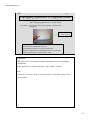
Resolution of the image
• Input resolution (resolution of the image) is different
depending on the film size and paper width each.
Change the resolution of the image by the zoom lens of
scanner.
7056
1940
1287
to
4680
Resolution of the image when scanning 135 film (Unit: pixel)
7
www.minilablaser.com
31D_2
2070
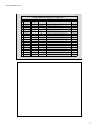
Resolution of the image (film size each)
Film size
Minimum
Maximum
135F
1287 x 1940
4680 x 7056
135H
1287 x 907
4680 x 3299
135P
685 x 1944
2491 x 7071
240C
951 x 1427
3170 x 4757
240H
951 x 1667
3170 x 5557
240P
692 x 1667
2307 x 5557
110
1593 x 2096
2500 x 3290
6 x 4.5
1147 x 840
4591 x 3362
6 x 6 (6 x 6V)
1149 x 1132
4599 x 4530
6 x 6H
1132 x 1149
4530 x 4599
6x7
1145 x 1404
4582 x 5617
6x8
1166 x 1572
4666 x 6290
6x9
1166 x 1698
4666 x 6794
Explanation
•In the 120 film, the resolution of the image is constant, but the width [6] of
[6*#] is slightly different depending on each size on the basis of the 120
size standard. Therefore, even if you scan it at the same magnification, the
resolution of image is to be the present size as a result, because the film
width with image is different.
•As for mounts, if the image is enlarged, the depth of field is shallow, so the
zoom value is constant.
Note
•In case of wide scanning for 120 and mount, the number of resolution for
scanning is as follows.
6*4.5W
------------ 4748*3673
6*6W (6*6VW) ------------ 4748*4720
6*6HW
------------ 4748*4834
6*7W
------------ 4748*5995
6*8W
------------ 4748*6755
6*9W
------------ 4748*7143
8
www.minilablaser.com
31D_2
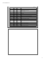
2070
Resolution of the image (film size each)
Film size
Minimum
Maximum
135F mount
1916 x 2937
135H mount
1916 x 1254
The resolution of the
image is fixed.
240 mount
1260 x 2214
Note
•In case of wide scanning for mount, the number of resolution for scanning
is as follows.
135F mount W
------------ 2178*3265
135H mount W ------------ 2178*1546
240 mount W
------------ 1518*2745
9
www.minilablaser.com
31D_2
2080
Minimum necessary pixels for paper size each
Size (mm)
82.5
89
102
127
152
Pixel
1040
1122
1286
1600
1915
Size (mm)
178
203
254
305
457
Pixel
2243
2558
3200
3843
5758
Note
•Calculating formula
Size (mm) / 25.4 x 320 (dpi) (resolution of printer) = Resolution of the image for one side
The above is just the calculated number. Actually the image is scanned a
little larger.
10
www.minilablaser.com
31D_2
2090
Scanning
The zoom value of scanner is decided on the basis of the
largest among the paper sizes, which are registered in
the print channel (C/P/H).
Example)
In the 135F, when setting “C: 89 x 127” and “P: 305 x 457”, the resolution
of image is 4680 x 7056. (Pre-scanning + Final scanning)
The resolution of image for 89 x 127 channel only is 1287 x 1940. (Final
scanning only)
The quality is different depending on the combination
of print sizes.
Explanation
•The quality is different depending on the combination of print sizes.
The size of output data is different because the output resolution is different.
•When two types of paper width below are set in the same print channel,
Pre-scanning + Final scanning is done.
Paper width for final scan only
Paper width for (Pre-scanning + Final scanning)
(Scan for the wider paper.)
11
www.minilablaser.com
31D_2
2100
Print channel and scanning
In case of 3R only
1940
1600
82%
1122
1287
%
24
5758
In case of interspersed channel
(3R and maximum paper size)
7056
82%
3843
4680
Input data
Output data
12
www.minilablaser.com
31D_2
2100
Pre-scanning
Film sizes
Resolution
Film sizes
Resolution
135F C
257 x 388
6 x 4.5
286 x 210
135F HD
216 x 388
6x6
286 x 283
135F P
136 x 388
6x7
286 x 351
135H
257 x 181
6x8
291 x 393
240C
252 x 379
6x9
291 x 424
240H
252 x 442
135 mount F
319 x 489
240P
183 x 442
135 mount H
319 x 209
110
343 x 452
240 mount
210 x 369
Explanation
•Same with the QSS-29/30.
•The image data scanned in the Pre-scanning is used for the index prints,
label index prints, index prints of contact print style photos and for monitor
display.
13
www.minilablaser.com
31D_2
2120
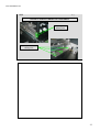
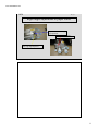
Digital ICE
Original image
Film
RGB scanning data
Lens
Mirror
CCD
for detecting
RGB images
The data with scratch
Corrected image
CCD for detecting scratches
Explanation
•The technology to make the images without scratch, dust, etc.
In addition to the CCD which takes the color information of RGB, the
another CCD is added. It detects the dust, scratch, etc. on the film. This
corrects the scanned image information.
14
www.minilablaser.com
31D_2
2130
Corrections by Digital ICE
Comparison table with the conventional models
Correct function
The image is corrected automatically by Digital ICE (option)
The conditions for functioning the Digital ICE
QSS-29/30
QSS-28/31
PCB, power
supply
Already attached when
shipping from the factory
Replace the image input PCB with
the D-ICE PCB (option).
Attach DC power supply 3.
Installing the
software
Reading the software of
Digital ICE (Z809072-01)
Read the system software program of
D-ICE PCB. (The D-ICE program is
included in the QSS system program
CD.)
Registration
in the mode
Mark the check box in the
“Operator selection” .
Mark the check box in the “Operator
selection” .
Explanation
•In the QSS-28, 31, the Digital ICE PCB also has a function of image input
PCB.
•In the QSS-29, 30, the D-ICE software has the role of protect key.
15
www.minilablaser.com
31D_2
2140
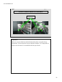
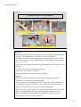
Scratches and dust which can be corrected
Light source side
Light
Light Light Light Light Light
Dust
Base
Red photosensitive
Negative
Green photosensitive
Blue photosensitive
Protective coat
The function of D-ICE: Effective
Effective Effective
Not
Not
effective effective
Scanner side
Dust
Effective
When it is possible to correct
(Example: In case of color negative)
Explanation
•The Digital ICE deletes the dust, scratch, finger print or mold, which is stuck to the
film surface, automatically.
•The scratch types below cannot be corrected.
Deep scratch goes though the emulsion side to base side of a film
Big scratch
•The Digital ICE does not function normally when a lot of silver is included in the
part where the image is created, like in case of monochrome films and desilvering.
In the KodakChrome films, the effect of Digital ICE is weak to the high density or
low density of a film, and the scanned image will deteriorate.
Turn OFF the function of Digital-ICE before printing.
•You can set the function of Digital ICE ON or OFF in the “Operator Selection”.
(However, in case of monochrome film, the Digital ICE is turned OFF
automatically.)
•The “blurring caused by the roller pressure” cannot be corrected.
Note
•The density of base for negative is light and the image cannot be detected when
scanning. In this case, turn OFF the D-ICE. It may enables to detect the images.
16
www.minilablaser.com
31D_2
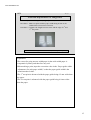
2150
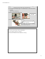
Colorimeter
* The colorimeter is adopted for the precise color matching
when carrying out the CMS.
* The conventional colorimeter measures the density of the color
of the paper. Therefore, there is a difference
between the actual print and the measured value.
*This colorimeter has an ability to distinguish like from the human's
eye, and the precision of color matching between the monitor and print
is increased.
* There are three types of colorimeter
– spectrophotometer, colorimeter, densitometer.
The colorimeter is used for this machine.
* The colorimeter can measure the color in CIE-XYZ/Lab value,
and color matching for difference devices is possible.
Explanation
• Comparing with the conventional densitometer, the colorimeter costs
more. However, the colorimeter is employed as the necessities to carry out
CMS.
• The measured range is same with that of conventional densitometer.
• For the maintenance of colorimeter, use the cleaning sheet for
densitometer. (Service tool)
17
www.minilablaser.com
31D_2
2160
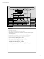
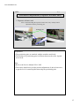
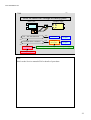
Paper sizes and transportation
Paper advance
In the QSS-31, there are two types of advance way.
Paper advance in single row, Paper advance in double rows
The condition of paper advance is as follows.
Condition of paper advance
Advance way
Paper width : 152 mm or less
Paper advance length: 216 mm or less
In double rows
Paper width : 152.1 mm or more
Paper advance length: 216.1 mm or more
Leading of order
50th print in one order
When feeding the leading edge of paper
When feeding the fogged paper
When feeding the spliced paper
In single row
* Refer to the Service Manual Chapter 5 for details.
18
www.minilablaser.com
31D_2
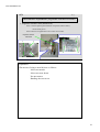
2160
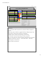
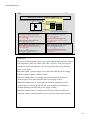
Paper sizes and transportation
The paper lane selection is carried out in the paper advance section
after exposure.
Lane selection is carried out by paper advance unit 2.
Paper advance in
single row
Paper advance unit 1
Paper advance unit 2
Paper advance unit 3
Paper advance in
double rows
Check the actual machine.
19
www.minilablaser.com
31D_2
2370
Laser Engine
Laser:
Abbreviation of
Light Amplification by Stimulated Emission of Radiation
In both the QSS-30 and 31, the exposure method by Visible Radiation
is employed.
Note
• Merit
1.It is possible to reduce the power consumption in the printer.
2.The uniformity calibration is unnecessary.
3.The laser is not affected by the magnetism.
20
www.minilablaser.com
31D_2
2380
Cautions concerning the laser
R laser is ON only when printing, but B, G laser is always ON.
Before servicing the machine, be sure to follow the following
instructions to avoid laser radiation exposure.
*Do not perform any work other than that which is specified in the
manual.
*Do not reflect the laser beam by inserting a mirror or the like in
the light path of the laser beam.
*Do not change the light path of laser beam.
*Do not replace the optical parts while the electricity of the laser is
ON.
*Do not turn ON the electricity in the removed exposure advance
unit.
*Do not turn ON electricity in the removed laser unit.
*Do not disassemble the laser unit.
Explanation
• The QSS-30 and 31 is IEC Class1 laser product.
21
www.minilablaser.com
31D_2
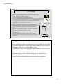
2400
(Note) IEC standard of Laser output
Class
Evaluation of danger
Labeling
Unnecessary
Explanation label
Class1
Produce radiation that causes no damage to
human body.
Class 1 laser products
Class2
Eyes are protected by the aversion (e.g. blink
of eyes).
Necessary
Do not look into the beam.
Class 2 laser products
Class3A
Eyes are protected by the aversion (e.g. blink
of eyes). However, it is dangerous to look
into the beam directly by the optical means.
Necessary
Do not look into the beam.
Do not look the beam directly with
optical devices.
Class 3A laser products
Class3B
It is dangerous to look into the beam directly.
However, the diffuse reflection does not
cause the damage to eyes.
Necessary
Do not look into the beam directly, and
do not touch it.
Class 3B laser products
Class4
The diffuse reflection causes the damage to
eyes at high risk, and it may cause the skin
disorder and fire.
Necessary
Both of Direct light and beam are
dangerous. Do not look or touch it.
Class 4 laser products
22
www.minilablaser.com
31D_2
2410
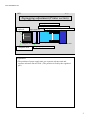
Printer Exposure Engine
Exposure way
Output
gradation
Maximum
exposure width
Print resolution
Line exposure method by the Laser engine
4096 gradation
QSS-30: 216 mm (8.5-inch)
QSS-31: 325 mm (approx. 12.8-inch)
320 dpi (Main Scanning) × 640 dpi (Sub
Scanning)
Exposure speed QSS-30: 50.8 mm/sec
QSS-31: 89 mm/sec
Light source
B laser, G laser, R laser
Explanation
• The exposure speed does not change depending on the input status (Under/Over).
• The maximum exposure width is the value including the hem for adjusting the
exposure center.
The maximum exposure width to the paper is as follows.
QSS-30: 210 mm
QSS-31: 305 mm
• Differences of laser unit between the QSS-30 and 31
1. There is only one laser synchronous sensor in the QSS-31 laser.
(Comparing with the QSS-30, the precision of fθ lens is improved, there is not
much difference between the refractive indexes of each RGB color.)
2. The polygon mirror of QSS-31 has 8 faces. QSS-30 has 6 faces.
The revolution speed of QSS-31 is higher than the QSS-30.
Note
• Frontier: 300 dpi x 600 dpi
• Differences of engines
CRT: Displays the image on the exposure surface by the electron beam, and
exposes.
HRCRT: Makes 3 colors B, G, R shine on the line by the electron beam, and
exposes.
MLVA: Controls the opening and shuttering time of minute electronic shutters,
and exposes.
DMD: Controls the reflecting time of minute mirrors, and exposes.
Laser: Controls the intensity of light, and exposes.
23
www.minilablaser.com
31D_2
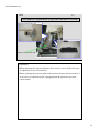
2420
Structure of Laser Unit
Mirrors
AOM
R laser
AOM
G laser
AOM
B laser
Polygon mirror
QSS-30: 6 faces
QSS-31: 8 faces
Prism
Fθ lens
Paper
Explanation
•In the QSS-31, the polygon mirror has 8 faces.
Note
•Show the picture. (image data)
•Role of lens
Enlarge --> Parallel --> Convergence
24
www.minilablaser.com
31D_2
2430
Explanation of laser unit
Laser
Visible Radiation Laser for R, G, B each
AOM
Acousto-Optic Modulator
Adjusts the strength and weakness of laser light.
Mirror
Changes the direction of laser light.
Prism
Mix R light, G light and B light into one light.
Polygon
mirror
Rotates in a certain speed and scans in the Optical resolution
(Main line). [QSS-30: 6 faces, QSS-31: 8 faces}
Fθ lens
Changes the angle of laser light according to the angle of
incoming light, and maintains the constant speed.
Explanation
• Rotational speed of polygon mirror
QSS-30: 12,800rpm
QSS-31: 16,819rpm.
• In the QSS-31, the polygon mirror has 8 faces.
25
www.minilablaser.com
31D_2
2440
Structure of Laser Unit (AOM)
*AOM controls the strength of laser light.
*The diffracted light of first order is used for exposure.
Laser
AOM
100 %
Diffracted light of
first order
20 %
Exposure
80 %
0-th order light
NOTE
The direct light is called 0-th order light.
Explanation
• When the voltage is not turned ON to AOM, the incoming laser beam
passes through as it is. (0-th order light)
• When turning ON the high frequency voltage, the ultrasonic waves occurs,
and the diffracted light which is separated from 0-th order light occurs.
(Diffracted light of first order)
• Change the rate of 0-th order light and the diffracted light of first order by
changing the high frequency voltage on AOM, and control the strength of
light (diffracted light of first order) to be used for exposure.
26
www.minilablaser.com
31D_2
2450
Structure of Laser Unit (Fθ lens)
Polygon mirror
Fθ lens
Polygon mirror
QSS-30: 6 faces
QSS-31: 8 faces
* The Fθ lens corrects the dispersion of linear velocity
caused by the angle of incoming beam.
θθ
Paper
A
A
B
Exposure center
Explanation
• The travel (distance) on the paper is different between “the light
outputted from the exposure center at the angle θ” and “further output
light at the angle θ” (As shown in the illustration, length A, B).
• The Fθ lens changes the angle of diffracted light according to the angle
of incoming beam, and corrects the difference of travel (distance)
on the paper.
•
In the QSS-31, the polygon mirror has 8 faces.
27
www.minilablaser.com
31D_2
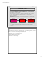
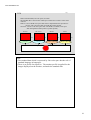
2460
Laser Exposure
Image data
Paper advance direction
Exposure position
Exposure image
Polygon mirror
QSS-30: 6 faces
QSS-31: 8 faces
Explanation
• Resolution
Optical resolution (Main or the CCD line): 320 dpi
Scan pitch (Sub Scanning): 640 dpi
• In the main scanning: Expose for 1 dot pitch each. In the sub scanning:
Expose for 0.5 dot pitch each
• In the sub scanning, the same color is exposed in 2 consecutive dots.
• Reason of “In the sub scanning, the same color is exposed by 0.5 dot pitch
each in 2 consecutive dots.”
1. Not to occur the open caused by the time-lag between the advance and
exposure.
2. Not to show the uneveness of color when the time-lag of exposure occurs.
• In the sub scanning, the same color of 0.5 dot is exposed in 2 consecutive
dots, so the color mixture of 0.5 dot appears.
When there is an abrupt change of color (e.g. primary colours to primary
colours), the color difference with the complementary color is bigger.
But, in the general images, it does not effect so much.
• In the QSS-31, the polygon mirror has 8 faces.
28
www.minilablaser.com
31D_2
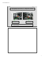
2480
Auto tuning
As for B, G laser, to get the stable outgoing laser beam, the
temperature of inside of laser is adjusted to the optimum
status automatically.
Timing to execute
When turning ON the
power supply
Fine tuning is executed.
“Laser temperature are being adjusted.” appears
on the monitor.
In the close down
checks
Before going into the program timer, Auto
tuning is executed. No message appears on the
monitor.
Occasion
When the Attention “1049. Execute auto tuning”
appears, execute the auto tuning in the Function
of laser unit adjustment.
Explanation
• The time to execute the fine tuning: 5 minutes (max.)
• The time to execute the auto tuning: 30 minutes (max.)
• Start the Fine tuning when the temperature around the B,G laser head is
within the allowable range (20 to 45 degrees). If the adjustment is not
completed in the Fine tuning (max. 5 minutes), the Auto tuning (max. 30
minutes) begins automatically. “Laser temperature are being adjusted”
appears from “before the allowable range” to “fine tuning or auto tuning is
completed”, and it is necessary to wait.
• It is desirable to execute the auto tuning once a day. So, when turning OFF
the breaker immediately after the close down checks, carry out the close
down checks after executing the auto tuning manually.
Note
• In the QSS-30, when the temperature of operational environment for
machine is low (out of regulated temperature), it takes a lot of time to
reach above processable temperature. (When the room temperature is
13°C or less, an approx. 5 hours is required.)
The heater is attached to the laser unit for preventing it. (Available from
Ver.C001)
29
www.minilablaser.com
31D_2
2900
Comprehension check
[Outline of the system]
*Do you understand the role of 2 CCDs inside of the scanner?
*Do you understand the specification of scanner?
*Do you understand the processable films by D-ICE?
*What is necessary for using the D-ICE?
*Do you understand that the number of pixels for scanning varies depending
on the print sizes?
*Do you understand the conditions of [advance in single row] and
[advance in double rows]?
*Do you understand the specification of laser?
*Do you understand when the Auto tuning/Fine tuning is executed?
[Question]
*What is the role of 2 CCD each of scanner?
*What is the number of pixels for scanner?
*What is necessary for using the Digital ICE?
*What films cannot be processed with the Digital ICE (out of specification)?
And, what is the reason for that?
*What is the print size that the number of pixels for scanning is different from “89 x 127
(135F)”?
*What is the condition of paper advance in double rows?
*What is the exposure time of laser?
*When is the Auto tuning executed?
*How long does it take for Fine tuning at the maximum?
30
www.minilablaser.com
31D_3
Chapter 3
Operation
1
www.minilablaser.com
31D_3
3000
The point of this chapter
Key points
• Study the operations.
Printing operations, Start up checks, Close down checks
ON/OFF procedure of power supply, Status display of LED
CD-Viewer, CVP (Correction Value Print), Index prints
Upon completion of the lesson, you will be able to:
*Explain each printing operation to users.
*Explain the image storing to media to users.
*Explain printing operations in the EDIT mode to users.
*Explain the input from Flatbed scanner to users.
*Explain the start up checks and close down checks.
*Explain ON/OFF procedure of power supply to users.
*Explain the status display of LED, details of CVP and index prints.
*Understand about the CD-Viewer.
How to proceed the training
Carry out the practical training, or explain the items using the sample prints.
2
www.minilablaser.com
31D_3
3010
Setup during the start-up checks
Daily setup
Weekly
setup
Monthly
setup
Execute once a day for each paper type to be used.
Correct the temporary aging of exposure engine, light source
and processing solution.
Make a 18-step test print.
Execute once a week. This is displayed instead of the daily
setup.
After carrying out the daily setup, carry out the printer profile
calibration to correct the temporary aging of data
characteristics for each printer. (Execute it for each paper type).
Make test prints.
18-step setup prints (daily setup)
16-step setup prints (printer profiles)
Execute once a month. After completing the daily setup or
weekly setup, execute it.
Carry out the monitor profile calibration to correct the
temporary aging of monitor.
Adjust the monitor again.
Explanation
• When you do not carry out the weekly setup and monthly setup at the startup checks, the display appears at every start-up checks until you carry out
the setup.
• The laser engine causes the temporary aging by the fall of maximum
output, change of output wavelength and dirt of optical parts.
3
www.minilablaser.com
31D_3
3030
Daily setup flow
Make a test print (18-step setup print)
When the light source
upgrading (auto) is carried
out correctly during the
program timer
When the light source upgrading
(auto) is not carried out correctly
during the program timer
Light source upgrading
OR
When 240 lane or 110AFC is set
during the program timer
Colorimeter calibration
Measure a test print.
Registration
Explanation
•
Carry out the “Colorimeter calibration” only when measuring first print. It is not
necessary to execute it every time when measuring the prints.
•
When the colorimeter calibration is not necessary, the input section judges it and
skips the display “Colorimeter calibration” automatically.
•
The light source is upgraded during the program timer as follows.
As for 135/240AFC, 110AFC, when the lane is set to 135 lane (135/240AFC), it
is executed automatically. When 240 lane or 110 AFC is set, it is not executed.
As for 120AFC, MMC/AMC, it is executed automatically for the carrier to be
set.
•
When the light source upgrading is not carried out during the program timer, it
is carried out again automatically for the carrier to be set in the daily setup.
And, when the 240 lane or 110AFC is set, the light source is updated for 135
lane during the daily setup.
Note
•
As for the other carriers except the one to be set during the program timer,
update the light source when replacing the carrier and switching the lane.
However, update the light source when 24 hours have passed from the last
update.
•
When the Printer control unit is connected, the light source update is not
executed.
4
www.minilablaser.com
31D_3
3040
Weekly setup flow
Carry out the Daily setup.
Make a test print. (16-step setup print)
Measure a test print.
Update the Printer profile data.
Registration
5
www.minilablaser.com
31D_3
3050
Monthly setup flow
Daily or weekly setup is completed.
Monitor brightness adjustment
Checking the color temperature
Contrast
Brightness
Measure the monitor display.
Updating the monitor calibration and profile
Explanation
•When adjusting the monitor at the monthly setup, the adjustment (monitor
side) is necessary.
Note
•In the QSS-31, when the Printer control unit is connected, the monthly
setup is not executed.
6
www.minilablaser.com
31D_3
3060
Explanation of operations
• Explain with the actual machine.
- Start-up checks
- Explanation of [HELP]
• Explanation of printing operations
• Carry out the practical training.
- Albums
- AMC
• Explanation of printing operations
- Carry out the practical training.
- Explanation of operation of FB scanner
Explanation
•As for AMC, up to 40 mounts can be set.
•Use the dummy mounts of AMC when switching the order.
•AMC is available for PJP.
•Components of AMC
Main body, Insertion stocker, Ejection stocker
Dummy mount (for switching the orders) Quantity: 5
Single adapter, Packing unit
•The operation screen is different between FB scanner manufactured by UMAX and
manufactured by EPSON.
•When the media output destination is CD-R/RW, it is possible to specify
[Number of media] and [number of label index prints].
[Number of media]: Can be set on the message [No.1527 Write the Data. Set the
media].
[Number of label index prints]: Can be set on the Order display.
•The following contents can be specified on the [Print operation] tab of Operator
selection screen.
[Color selection of print blank of positive]: Possible to select White or Black for
the unexposed part.
[Paper remaining count display]: Possible to select [Count distinct paper magazine
A and B] or [Count mix paper magazine A and B].
7
www.minilablaser.com
31D_3
3070
Explanation of modes
*Explain the modes, checking the actual machine.
Explanation
•Paper temperature change correction
R light changes by the temperature change of inside of laser unit and surrounded
temperature. The color development of paper may be different.
In this case, input the correction value in the “Paper temperature change correction”.
Corrections: Refer to the Operator’s Manual (Additional operations Chapter 3-6).
•The role of synchronous sensor is to control the start timing when the paper is
exposed by the laser light.
“Synchronous sensor Automatic Adjustment” is to adjust the Laser Output.
‘Laser light irradiated around the synchronous sensor’ is reflected
and it is prevented from diffusion inside of the laser unit.
This adjustment is required when replacing the laser unit.
•CCD noise suppression strength
Correction which is effective only for Under/Over part of films.
Noise is likely to occur in parts where there is not much light, so the
correction is done only for the part.
Note
•As for the setup and mechanical adjustment, carry out the practical training,
so skip the explanation here.
8
www.minilablaser.com
31D_3
3080
Shortcut key
•
Explain, checking an actual machine.
Shortcut key
PASS (F11) REP (F2)
(
Mode
Setup
Y (F5)
Maintenance
M (F6)
Version check
C (F7)
History of movement
D (F8)
Machine specification
-1 (F9)
Operator selection
N (F4)
List of Print channel
+1 (F10)
Option registration
) : Shortcut key in the Full keyboard
Explanation
• The above Shortcut key is used very often.
9
www.minilablaser.com
31D_3
3140
NCE mode
It is possible to control the output of laser and correct the color (Cyan, Yellow, etc.)
around the letter by inputting the correction value in the “NCE” mode.
(e.g.)
Outline characters on the black background
The part around black letter on the white background
However, the trend of color changes depending on various conditions (Font type, Font
size, condition of processing solution, etc.). So, even if you make a perfect correction
to a condition, the same quality cannot be gotten for the other conditions.
Description********************************
Light
Light amount of laser is not constant in one dot, not like the ideal
amount
waveform (illustration). The light amount is maximum at the center,
and it is getting smaller gradually as it is close toward the radial
rake.
Therefore, the low density part appears on the half-tone dot meshing
part (illustration), and this part may be colored Cyan, Yellow, etc.
depending on the chromogenic property of paper.
It is not noticeable in the consecutive color. But, it is noticeable in
the following scene.
The scene that the density difference appears clearly, especially
outline characters on the black ground, black letter around the white
background.
Perfect waveform
Laser beam
1 dot
Note
• This mode is open to the users. But, the trend of color changes depending
on the conditions (which are mentioned in the above Slide) and the perfect
correction is impossible. Now, use this mode following a service person’s
instructions. Refer to the Service Manual 3065.
If the customer is not satisfied with the quality when the correction value
is not inputted, input the value in this mode.
• The part around the letters may be colored also when the exposure position
adjustment and exposure zoom fine adjustment are not carried out
correctly. Before carrying out the correction in the NCE mode, check the
exposure position adjustment and exposure zoom fine adjustment.
10
www.minilablaser.com
31D_3
3150
CD Viewer
Simple Viewer Software
In the QSS-27 or later, the Viewer
Software is standard.
Up to 5 orders can be displayed.
If you install the CD viewer utility
software, you can set the customer’s shop
information and logo data on the viewer
software.
Explanation
<Explanation of Main function>
• Select the image data of film.
The images are put in order for each film. (Maximum: 5 orders)
• Set the image size for display.
You can select the display from 3 patterns.
Big size/ Middle size/ Small size
• Slide show
You can select various slide display patterns.
• Store the image to each media.
You can specify the image form and store it to the media.
• Mail attachment
You can attach your favorite photos in the mail automatically.
• Pint order form
You can make a print order sheet. The enables to make a print from the
images in the CD.
• Set the display screen
You can select the image quality for image display.
11
www.minilablaser.com
31D_3
3160
CD Viewer
Deluxe viewer software
Up to 5 orders can be displayed.
If you install the CD viewer
utility software, you can set the
customer’s shop information and
logo data on the viewer software.
The deluxe viewer software is not sold as the software.
So, you can not write the deluxe viewer software from a machine to generic CD-R and R/W.
The QSS CD is supplied from NORITSU.
The Deluxe Viewer software is contained in the QSS CD in advance.
Explanation
<Function of explanation>
• Image display
1 frame, 3 frames, 6 frames, 15 frames, Index display
Slide show
Store in my photo
• Corrections
Red-eye Correction, Brightness, Noise Removal, Contrast, Sharpness,
UnSharp, Saturation
• Special effects
Puzzle, Solarize, Monotone, Sepia, Mosaic, Blur, Pointillize, Emboss
• Print order
Make a print order sheet, and you can order through DPEgg.
• Make the post cards
12
www.minilablaser.com
31D_3
3170
QSS CD
The QSS CD is supplied from NORITSU as an option.
The Deluxe Viewer software is contained in the QSS CD in advance.
<Kinds>
Name
Contents
Record
Label
QSS CD (TYPE A) Deluxe Viewer QSS CD
Source of Supply
Attachment
NORITSU
Nonwoven fabric
Manual
QSS CD (TYPE B) Deluxe Viewer Printable
Each CD has part number.
The attachment is stored in the CD-R case.
Explanation
•The deluxe viewer software is not sold as the software.
So, you cannot write the deluxe viewer software from a machine to CD-R
and R/W.
13
www.minilablaser.com
31D_3
3180
CD-R Engine
*In the QSS-27 or later, the CD-R Engine is the software to write the image to
QSS-CD that contains the Deluxe viewer software. (Windows/Mac)
*In the QSS-27 or later, this software is required to see the Simple viewer
software in the Mac.
*There are two types of CD-R Engine. The QSS software version and
installing method is different, but there is no difference in the function.
CD-R Engine (Windows/Mac)
Noritsu CD-R Engine (Windows/Mac)
Explanation
•CD-R Engine software (Windows/ Mac) is necessary for the availability of
the Deluxe viewer software .
•Noritsu CD-R Engine (Windows/Mac) is made by Noritsu.
Note
•The Viewer software is available for both of Windows and Mac.
But, the viewer starts up automatically only in the Windows.
14
www.minilablaser.com
31D_3
3190
Compatible software version for CD-R Engine
Compatible software version for CD-R Engine (Windows/Mac)
QSS-2701D
Ver.F001 or later
QSS-2801D
Ver.D001 or later
QSS-2901D
Ver.C001 or later
QSS-3001D
Ver.C001 or later
QSS-3101D
Ver.A001 or later
Software version which is compatible or will be compatible with
Noritsu CD-R Engine (Windows/Mac)
QSS-2701D
Not supported
QSS-2801D
Ver.G001 or later
QSS-2901D
Ver.E001 or later
QSS-3001D
Ver.E001 or later
QSS-3101D
Ver.C001 or later
Explanation
• CD-R Engine (Windows/Mac) is replacing Noritsu CD-R Engine
(Windows/Mac) in turn. (except QSS-27)
• Even when CD-R Engine (Windows/Mac) is used, it can be used in the
software version (mentioned in the above list) or later.
15
www.minilablaser.com
31D_3
3200
Installing the Mac CD for compatible software version each
QSS software
Type of CD-R Engine to Installing the Mac
be installed
CD
QSS software which is Noritsu CD-R Engine
compatible with Noritsu (Windows/Mac)
CD-R Engine
CD-R Engine
(Windows/Mac)
(Windows/Mac)
Unnecessary
QSS software which is
not compatible with
Noritsu CD-R Engine
(Windows/Mac)
Necessary
CD-R Engine
(Windows/Mac)
Necessary
Explanation
• Installing the Mac CD is different depending on the combination of QSS
software version and type of CD-R Engine.
16
www.minilablaser.com
31D_3
3210
Procedure of installing the CD-R Engine (Windows/Mac)
1. Install the CD-R Engine software (Windows/Mac) in the Win 2000.
*Caution
When the display appears during
the installation, set like below by
pressing [Browse].
(as show in the left illustration )
C:¥Program Files¥ cdr
2. Install the software from Mac CD folder in the system program CD of each machine.
If you do not install the CD-R Engine software, the Viewer software for Mac does not start up.
Explanation
•As for Noritsu CD-R Engine (Windows/Mac), there is no special caution.
Refer to the Service Manual [3874].
17
www.minilablaser.com
31D_3
3220
CD Viewer Utilities
This is the software to edit the display
contents of CD Viewer.
You can set the customer’s shop
information and logo data.
Rainbow Photo
Kaigan-dori2-7-68 Tokyo TEL 03-3333-3333
Open 9:00 – 20:00
Simple viewer software and Deluxe
viewer software are common.
Install the software from “CD_Viewer_Utility” folder in the system program CD of each machine.
18
www.minilablaser.com
31D_3
3230
Setting of the CD-R/RW writing
●When writing to the QSS CD
Set in the “Image Save” of “Operator Selections”.
Mark the check box for “Switch for Deluxe Viewer”.
Set the “Shop data” folder.
●When writing the generic CD-R/RW
Set in the “Image Save” of “Operator Selections”.
Remove the check box “Switch for Deluxe Viewer”.
Mark the check box “Writing Viewer Software”.
Set the “viewer software” folder.
(The simple viewer software which is standard of this product
is set in the initial setting. )
Explanation
•If you install “CD-R Engine (Windows/Mac) software, you can set the
“Switch for Deluxe Viewer”.
•As for the registration of “shop data”, refer to the “CD Viewer Utility
software” Operator’s Manual.
19
www.minilablaser.com
31D_3
3240
ON/OFF procedure of power supply
PC begins shutdown.
Close down
checks
30
minutes
The time to start temperature
adjustment
200V power supply
OFF
The start up of
PC is completed.
5
minutes
5
minutes
Manual sorter switch
OFF
Blinking
ON
The shutdown of PC
is completed.
Wait for cooling the scanner lamp and
Auto tuning
OFF
The PC begins start up.
The PC is activating.
Explanation
•After the close down checks, the time to start PC shutdown is 30 minutes.
This is the maximum time required for Auto tuning.
This time is different depending on the operational temperature of machine.
The time is normally approx. 15 to 20 minutes.
If the Auto tuning (max.30 minutes) is not completed normally, the
shutdown of PC is started after more 30 minutes have passed. (In this case,
it takes max.60 minutes in total.)
Note
•The waiting time for cooling the scanner lamp (12 minutes) is necessary. It
is executed at the same time, so it is completed within above time.
20
www.minilablaser.com
31D_3
3250
Normal shutdown movement
(Close-down check is completed.)
Scanner lamp is OFF
“Program timer is activating.” is displayed (on the monitor).
Shutdown of PC [30 minutes (max.) later after the close-down
check]
The switch of QO is ON.
The power supply (200V supply) is OFF. [35 minutes (max.) later after the
close-down check]
The power supply of peripheral CPU and cooling fan is OFF.
Explanation
•The power consumption can be decreased at 40 % when the program timer
is activated.
21
www.minilablaser.com
31D_3
3260
Normal start up movement
(when the program timer is activated.)
During the Program timer
(“After the PC shutdown is completed” to “The time to start the
temperature adjustment”)
(The time to start the temperature adjustment)
The power supply is ON. (200V supply) The power supply of
peripheral CPU is ON.
The PC is started up. (3 minutes later after the power supply is turned ON.)
“The processing solution temperatures are being adjusted” is displayed (on the
monitor).
After the temperature adjustment is completed, “Would you like to proceed to the
operation mode?” is displayed (on the monitor).
Press [YES] key to go to the operation mode.
Explanation
•Set the program timer so that the start time of temperature adjustment is 1H
and 15 minutes or more before the work.
It is required to stable the scanner lamp before executing the light source
upgrade. So, the light source upgrade starts 50 minutes later after PC starts
up.
22
www.minilablaser.com
31D_3
3270
How to start-up except when the program timer
(when the breaker is turned ON)
•When starting up during the program timer
(“The shutdown of PC is started” to “The time to start the temperature
adjustment”)
The power supply is turned ON by pressing the QO switch for 2 seconds or more.
Then, PC starts up 3 minutes later.
•When starting up during the shutdown of PC
(“For 30 to 35 minutes after close down checks until the power supply is turned
OFF”)
Press the QO switch for 2 seconds or more. The power supply is turned OFF,
and the power supply is turned ON again. Then, the PC starts up 3 minutes
later.
•When starting up in the cases below
“The processing solution temperatures are being adjusted”
or “Before the shutdown of PC is started after the close down check is
completed.”
“Would you like to proceed to the operation mode?” is displayed by pressing a
key of keyboard. Press [YES] key to go to the operation mode.
Explanation
•As for the re-start immediately after the close down checks, it can be
carried out until the display “Program timer is being activated.” disappears.
(= until the Auto tuning is completed.)
23
www.minilablaser.com
3280
31D_3
How to start-up after the breaker is turned OFF
* When turning the breaker OFF during the program timer
(“The shutdown of PC is completed” to “The time to start the
temperature adjustment”)
The program timer becomes activating by turning the breaker ON.
The power supply is turned ON by pressing the QO switch for 2
seconds or more. Then, the PC starts up 3 minutes later.
* When turning the breaker OFF except during the program timer
The power supply of printer section and processor section is turned
ON. Then, the PC starts up 3 minutes later.
*When the PC does not start up (error)
Turn the breaker OFF and attach the jumper for start-up on J/P678
of power PCB 2. Then, turn the breaker ON.
Explanation
•As with the QSS-28/29, the QSS-31 has the jumper for start up.
24
www.minilablaser.com
31D_3
3290
How to turn OFF the breaker
* How to turn OFF the breaker after the close down checks
(e.g. When you do not use the function of the program timer)
When 30 minutes (max.) have passed after the close down check is
completed, the shutdown of PC is started. When 35 minutes (max.) have
passed after the close down check is completed, the power supply is turned
OFF. At this time, turn OFF the breaker.
* When turning the breaker OFF in case of troubleshooting, etc, press [F]
key in the “Close down check” mode and select “Turn OFF the power
supply”. After confirming that the power LED of PC is OFF, turn OFF the
breaker.
Caution
*Turn OFF the scanner lamp, and wait for 10 minutes or more. After that,
turn OFF the breaker. The lamp may be damaged.
25
www.minilablaser.com
31D_3
3300
How to turn OFF the breaker
when the PC has been freezing
1.
Check the LED of HD.
When the LED of HD is lighting or blinking, the HD is activating.
If turning the power supply OFF when the HD is activating, the HD may be
damaged.
Wait until the LED is turned OFF.
2.
Turn OFF the power supply of PC by pressing the SW of PC for
4 seconds or more.
3.
Turn OFF the breaker of processor.
Wait for approx. 10 seconds after turning the breaker OFF. And then
turn the breaker ON.
Explanation
•The movement time of HD is different depending on the data capacity
which is being processed.
•In the movement time of HD, the processing speed is getting slower as you
increase the data capacity.
•When the LED of HD is not turned OFF, turn OFF the power supply of PC
after confirming that the data is not being processed.
26
www.minilablaser.com
31D_3
3310
How to turn OFF the breaker in an emergency
* When turning OFF the breaker in an emergency, turn OFF the
breaker of the processor.
The UPS activates and the PC is shutdown.
The time to shutdown changes depending on the status of PC.
(for a few minutes to 20 minutes)
* When turning OFF the breaker of the input section
Use the breaker of input section only when you cannot turn OFF the
breaker of processor section in an emergency.
* How to turn OFF the breaker of input section
1. Turn OFF the breaker of output section.
2. Turn ON the breaker of input section.
3. Turn ON the breaker of output section.
The power supply of input section and output section is
turned ON and the PC is started up 3 minutes later.
Explanation
•”In an emergency” means the cases below.
-Smoke is pouring out of the machine.
-It may hurt a person unless you stop the machine.
And, the abnormal sound is heard, open the processor upper cover or the
printer door and stop processing the paper.
27
www.minilablaser.com
31D_3
3320
Status display of the processor
Status lamp of processor
Condition of display
Note
Lighting Green
The temperature adjustment is completed.
Blinking Green
During the program timer
(From “After the close down checks is completed.” to
“The time to start the temperature adjustment”)
Slow
blinking
Blinking Red
When it is impossible to activate the temperature
adjustment (When the error occurs or the interlock
switch is activated.)
Slow
blinking
Dark
The input section is not started-up. During the
temperature adjustment
Sorter switch
Condition of display
Dark
The PC is being functioned.
Blinking
While the PC is being started-up.
Lighting
During the program timer or the power supply
of PC is turned OFF.
Note
Slow blinking
28
www.minilablaser.com
31D_3
3330
Status display of AFC
Ready lamp
Condition of display
Lighting Green
Processing films is possible. (You can insert a film.)
Blinking
Green
Film is being processed. (You cannot inset a film).
Blinking Red
Films cannot be processed. (You cannot process a film.)
*The error occurs. (You cannot process a film.)
* The error occurs. (You cannot print.)
Dark
Films cannot be processed.(You cannot process a film.)
*When the “Film” is not selected for “Image input” in the print channel
setting.
*During the start-up checks and close-down checks
*During the program timer
*When the message “Insert a film.” does not appear on the adjustment
mode.
*During the initial movement
29
www.minilablaser.com
31D_3
3340
Details of the back print (Film/Media)
* Film and media except 240
NORITSU <12> 005
(X)
(I) (K)
FBS T
(D) (E)
(F)
284 15 +1+1+1+1 +30 AC01 Acs –10 Ach -10 AS02 SA200 GR10 MSu10 RE01 SF02 FC01 XF02 R090 Z123/200
(J) (L)
(M)
(N)
(O)
(P)
(Y)
(Z)
(U)
(Q)
(R)
(S)
(T)
(V)
(W)
* For 240 (TYPE1)
BIRTHDAY EL25 MGhi FFn BVvh Alh PAc SUnC CH1 LAB01
CD T
(A)
(B)
(C) (D) (E) (F)
01.05.29 11:57A 001-001 (12) 284 005 15 +1+1+1+1 +30 *Digital correction data
(G)
(H)
(I)
(J) (K) (L)
(M) (N) (Same with films except
240)
* For 240 (TYPE2)
BIRTHDAY EL25 MGhi FFn BVvh Alh PAc SUn CH1
(A)
(B)
29/MAY/01 11:57A ID001-001 (12)FTPM LAB01
(G)
(H)
(I)
(C)
(D)
Explanation
•Blue letter: the data for digital correction
30
www.minilablaser.com
31D_3
3340
(A)
Title
(K)
Print count
(B)
Camera information
(L)
Print channel
(C)
LAB ID
(M)
Color, density correction (YMCD)
(D)
Copyright mark
(N)
Scanner correction
(E)
Input medias
(O)
Auto contrast correction value
(F)
Template
(P)
Auto sharpness correction value
(G)
Date, Time
240 TYPE2: the month is displayed in 3
letters (English letter).
(Q)
Red-eye correction value
(R)
Soft focus correction value
(S)
Color conversion
Color image: FC, Monochrome: MoF,
Sepia: SeF
Film ID (FID)
240TYPE2: ”ID” is displayed before the
number.
(T)
Cross filter correction value
(H)
(I)
(J)
(U)
Moire repression
(V)
Rotation angle of the image
Frame number
240TYPE2: FTPM or SERIES is displayed
after the frame number.
In the case of input from storage media,
the file name is printed. (file name +
extension)
(W)
Zoom and crop of the image
Order number
(X)
Backprint
(Y)
Chroma correction
(Z)
Graininess repression correction
Explanation
•Blue letter: the data for digital correction
•The Digital correction data is not printed if the correction is not done.
•The number of letters for the CVP is different depending on the paper advance length.
(e.g.)
In the APS, if the paper advance length is 152 mm or less, the date is not printed.
If there is not enough space for printing on the paper, the digital correction value may not
be printed.
The “contrast” value has a first priority, and the data is printed as much as possible.
The margin is 4 mm on the both side of the paper.
•Details of the Auto contrast
AC: Auto contrast (The Whole)
ACs: Auto contrast (Shadow)
Ach: Auto contrast (Highlight)
•Details of scanner correction
When printing with the “Digital image auto correction” ON, [NN] is imprinted.
When printing with the “Positive film auto correction” ON, the scanner correction
value is imprinted.
This is available when the following system program version is released.
QSS-28: Ver.G001 or later
QSS-29: Ver.D004 or later
QSS-30: Ver.E001 or later
QSS-31: Ver.C001 or later
31
www.minilablaser.com
31D_3
3350
Details of the back print (EDIT)
* Edit
BIRTHDAY 123 T
(A)
(K)(D)(F)
284 15 〈CUSTOMERINFO.mdb 1234
(J) (L)
(1)
(2)
* Back print data only for editing
(1)
File name for customer information
(2)
Customer number for
customer information
32
www.minilablaser.com
31D_3
3370
Types of index prints
Normal index prints
Make normal index prints.
The data for displaying on the PJP mode is used.
Label index prints
Index print for the media case size of storage
media
No index print for smart media, PC and
compact flash
Contact Print Style
Photos
Make Contact Print Style Photos.
135F only
As for the index prints in the above list, the print quality can be selected.
(Operator Selection)
Standard: Default
High quality: The quality of image is improved, but the processing capacity
is slightly lower.
*High quality: This is different from the HQ print of QSS-27.
Explanation
•The pre-scanning data is used for the output of index print when both of
“Standard” or “High quality” is selected.
•The pre-scan data is enlarged and prints are made.
•High quality: The image is enlarged, but the image quality is improved.
•Index logo data size
When you make an original logo data;
Image size: 164 x 494 pixels
Storing format: bitmap (bmp)
•In the QSS-28, explain to the users that DLP logo print can be used for
index prints. (Be sure to explain above contents on the contract of TI
company.)
33
www.minilablaser.com
31D_3
3380
Index print sizes (135/240 films)
Format
Normal index prints
135/240 films
O : Available
- : Not Available
∆ : Printing is possible,
but a whole of the image does
not appear on the print.
Paper size
(mm)
240 film
135 film
28-frame
40-frame
15-frame
25frame
40frame
3HS
82.5 x 158
-
O
-
-
-
3R
89 x 127
O
O
O
O
O
3HD
89 x 158
O
O
O
O
O
3W
89 x 178
-
-
O
O
O
3WS
89 x 178
O
O
O
O
O
4R
102 x 152
O
O
O
O
O
4HD
102 x 178
O
O
O
O
O
5R
127 x 178
O
O
O
O
O
6R
152 x 203
O
O
O
O
O
6HD
152 x 254
O
O
O
O
O
6W
152 x 305
O
O
O
O
O
8RS
203 x 254
O
O
O
O
O
8R
203 x 305
O
O
O
O
O
8HD
203 x 356
O
O
O
O
O
CD_40
120 x 120
-
O
-
-
∆
CD_40A
89 x 120
-
O
-
-
∆
CD_40B
102 x 120
-
O
-
-
∆
Explanation
• There are 3 types of Index print sizes for CD.
• 135 film restrictions
When selecting 3HS, CD_40/40A/40B, it is printed in 40-frame format.
• 240 film restrictions
When selecting CD_40/40A/40B, it is printed in 40-frame format.
But, a whole of the image does not appear on the print because the aspect
ratio is not constant.
Note
• 110 film restrictions
Same with the restrictions of 135 films. But, a whole of the image does
not appear on the print because it is printed in 135 format.
• Media
Same with the restrictions of 135 films. But, a whole of the image does
not appear on the print because the aspect ratio is not constant.
34
www.minilablaser.com
31D_3
3390
Index print sizes (120 films)
Format
Normal index prints
120 films
- : Not Available
Q: Printing is possible, but the logo data is
not printed.
6*4.5, 6*6
: 18-frame format
6*7, 6*8, 6*9 : 12-frame format
∆ : Printed in 28/40-frame format (same
with 135 film), but a whole of the image
does not appear on the print.
Paper size
(mm)
Index
3HS
3R
3HD
82.5 x 158
89 x 127
89 x 158
12frame
∆
∆
∆
18frame
∆
∆
∆
3W
89 x 178
-
-
3WS
4R
4HD
89 x 178
102 x 152
102 x 178
∆
Q
∆
∆
Q
∆
5R
6R
6HD
6W
8RS
8R
8HD
127 x 178
152 x 203
152 x 254
152 x 305
203 x 254
203 x 305
203 x 356
∆
∆
∆
∆
∆
Q
∆
∆
∆
∆
∆
∆
Q
∆
CD_40
CD_40A
CD_40B
120 x 120
89 x 120
102 x 120
∆
∆
∆
∆
∆
∆
Explanation
• There are 3 types of Index print sizes for CD.
• 120 film restrictions
- The logo data is not printed.
- When selecting 4R, 8R, the number of frames to be printed is different.
Film size 6 x 4.5, 6 x 6: 18-frame format
Film size 6 x 7, 6 x 8, 6 x 9: 12-frame format
- When selecting the size except [4R] and [8R], it will be printed in 28frame and 40-frame format and a whole of the image does not appear
on the print.
- When selecting CD_40/40A/40B, it is printed in 40-frame format, and a
whole of the image does not appear on the print.
35
www.minilablaser.com
31D_3
3400
Background color for index prints
*The color can be selected as a background color of
an index print.
1. Gray
5. Orange
2. White
6. Green
3. Pink
7. Light blue
4. Yellow
8. Purple
9. Black
is for Contact print style photos.
Note
•Select the background color for [135/120/110/Media], [IX240] and
[Contact print style photos] each.
36
www.minilablaser.com
31D_3
3410
Label index prints
Types of media
FD
MO
Zip
CD/DVD/HD
Size
89 x 114
89 x 117
97 x 120
120 x 120
(12 cm CD’s)
80 x 85
(8 cm CD’s)
89 x 120*
102 x 120*
Format
(number of frames)
6, 20, 35
6, 20, 35
6, 20, 35
40
Used
Used
Used
Used
Index logo
Note
The number of
frames are
switched
automatically.
The number of
frames are
switched
automatically.
The number of
frames are
switched
automatically.
The number of
frames are fixed.
*:
[89 x 120] or [102 x 120] is selected automatically.
When the magazine with 102 paper width is not set: [89 x 120]
When the magazine with 89 paper width is not set: [102 x 120]
Explanation
•The label index is made automatically at the same time of storing the
images to media.
However, you can set “None” for the label index print.
•When the paper width is larger than the print size, the image is centered, so
the unexposed part appears on both sides of the print.
•The size of Label index prints for CD are switched automatically according
to [CD type] setting which is selected in [Option registration] Æ [Media]
Æ [CD-ROM (CD-R/RW)].
And, the size of Label index prints for Business card CD’s and other
uniquely shaped CD’s are also the same.
37
www.minilablaser.com
31D_3
3420
Index print sizes for Contact Print Style Photos
Paper sizes for 6-frame
Name
CP6_1
CP6_2
CP6_3
CP6_4
CP6_5
CP6_6
CP6_7
Paper width
(mm)
82.5 or
more
82.5 or
more
120 or
more
165 or
more
203 or
more
240 or
more
240 or
more
228.6
228.6
228.6
228.6
228.6
228.6
263
Paper advance
length (mm)
Paper sizes for 4-frame
Name
CP4_1
CP4_2
CP4_3
CP4_4
CP4_5
CP4_6
CP4_7
CP4_8
Paper width
(mm)
82.5 or
more
82.5 or
more
120 or
more
152 or
more
152 or
more
152 or
more
152 or
more
152 or
more
152
152
152
152
191
227
263
300
Name
CP4_9
CP4_10
CP4_11
Paper width
(mm)
152 or
more
152 or
more
152 or
more
336
372
407
Paper advance
length (mm)
Paper advance
length (mm)
Size:
When printing the paper to be used with the
minimum necessary paper width.
135F/110/120 only is available.
Explanation
•The frame (format) of contact print style photos can be selected in the
Index setting of print channel.
•When making contact print style photos with 120/110 films, the print is
made with 135 frame.
•It is possible to read the frame data of contact print style photos. (Bitmap,
3632 x 549 pixel)
Note
•CP of CP4_1 stands for Contact Print Style Photos.
38
www.minilablaser.com
31D_3
3430
Index prints for Contact Print Style Photos
*Contact index prints
CP4_1
CP6_1
CP4_8
CP6_3
Explanation
•As for the Contact Print Style Photos, the following types are available for
each machine.
Contact Print Style Photos with 4-frame:
QSS-28:
(1-line to 8-line)
QSS-29/31:
(1-line to 11-line)
QSS-30:
(1-line to 9-line)
Contact Print Style Photos with 6-frame:
QSS-28:
(1-line to 3-line)
QSS-29/31: (1-line to 7-line)
QSS-30:
(1-line to 5-line)
•The Contact Print Style Photos are not available for IX240.
•In the Contact Print Style Photos, the printing direction (horizontal or
vertical) is changed, depending on the paper width.
39
www.minilablaser.com
31D_3
3440
Practical training
*Carry out the practical training.
- How to exit from the close down checks mode.
- How to finish the application.
- At the close down checks, set the 135/240AFC to 135
lane.
Explanation
•If you carry out the disk defragmentation regularly, it can shorten the
required time to defrag.
40
www.minilablaser.com
31D_3
3450
Front print from Media
Digital camera media
YES
YES
DTM data is included
Imprinting specification of DPOF
in the image.
(Setting including DTM)
Print the data
of exposure
NO
NO
YES
Imprinting specification of EXIF
(Not print)
NO
YES
Date 1 exists in Exif.
NO
YES
Date 2 exists in Exif.
Imprinting the latest
saving date
Without the imprinting of date
NO
Explanation
• Refer to the Operator’s Manual –Additional operations- for the Front print
setting.
• If there is no DPOF data even when the front print setting is ON, it is not
imprinted. If [Print] is selected for Exif imprinting setting, however, date
of Exif data for image is printed.
• [DTM] : {DATA TIME}, data of date of exposure
• Date 1 (Exif) : {Data Time Original}, data of date of exposure
• Date 2 (Exif) : {Data Time Digitized}, date of edit by Photoshop, etc.
41
www.minilablaser.com
31D_3
3900
Comprehension check
[Operations]
*Can you explain the display contents of [ORDER] screen?
*Can you explain the operations of [HELP]?
*Can you explain the image storing to media?
*Can you explain the image sizes (16base, 4base,…..)?
*Can you explain the cautions in handling the smart media or compact flash?
*Can you do “Print to Print”?
*Do you understand the input resolution and output resolution?
*Can you explain the differences (merit/demerit) of letter printing in Edit mode and
Frame print?
*Can you explain how to make ID Photos?
*Can you explain the start up checks and close down checks?
*Can you explain the procedure of daily setup?
*Can you explain the procedure of weekly setup?
*Can you explain the procedure of monthly setup?
*Can you explain the procedure of power reset?
*Can you explain the kind of CD-Viewer?
*Can you explain the role of NCE mode?
[Question]
*Explain the meaning of each icon in the [ORDER] display.
*Register the page (item) of manual you usually use in the HELP.
*Explain how to store the images to CD (images of 2 orders).
*Explain the differences between 16Base, 4Base, Base and 1/4base
*As for the smart media, the images are sometimes damaged. What is the cautions in
handling it?
*Explain how to make 7R print from 3R print.
*What are the merits and demerits of Edit mode and letter printing (Frame print)?
*Explain how to make ID photos.
*Explain weekly maintenance of upper turn racks and squeeze rack.
*In which case is the light source upgrading done during the daily setup?
*Explain the flow of weekly setup briefly.
*Explain the flow of monthly setup briefly.
*”The movement of printing is a little strange. You want to reset the power supply.” What
is the procedure at this time?
*”Keyboard and mouse do not work. You want to reset the power supply.” What is the
procedure at this time?
*”The paper is jammed in the processor, and the abnormal sound is heard in the racks. You
want to turn OFF the power supply.” What is the procedure at this time?
*Which tool is necessary for making the Deluxe Viewer CD?
42
www.minilablaser.com
3900
31D_3
[Operations]
*Can you explain [Shortcut] function?
*Can you explain Noritsu CD-R Engine (Windows/Mac)?
*Can you explain the role of disk defragmentation?
*Can you explain the data which is effective for Front print?
[Question]
*Explain how to make label index print of 8 cm CD’s.
*Explain the method of disk defragmentation.
43
www.minilablaser.com
31D_4
Chapter 4
Installation
1
www.minilablaser.com
31D_4
4000
The point of this chapter
Key points
•
Study the installation of the machine.
Width for carrying a machine, Space for installation, Packing items,
PC peripherals, Allocation of drives, Setting the language specification
Upon completion of the lesson, you will be able to:
*Understand the width for carrying a machine and space for installation and judge whether
it is possible to bring a machine to a customer’s shop.
*Understand the packing parts and judge whether all parts are prepared in the installation.
*Understand the angle brackets to be removed in the installation and the parts to be attached,
and work smoothly.
*Execute the following things. - Setting of language specifications, Each setting after
attaching each drive, Allocation of drives -
How to proceed the training
•The trainer will provide an oral explanation of the cautions, referring to
“Installation Manual” and a machine.
•Carry out the mechanical adjustment or installation of options in the other
chapter. You do not carry out the practical training here.
2
www.minilablaser.com
31D_4
4010
The width to carry a machine
Unit : mm
The minimum
height
The minimum
width
SI-2600
1,285
800
LP-2200
1,205
770
PP-1223
1,500
780
Printer control unit
1028
500
3
www.minilablaser.com
31D_4
4020
Space for installation
3101
Unit: mm
3483
200
2138
150
945
100
610
650
1570
1480
770
950
100
2438
Refer to the Specification Manual for details.
Explanation
•Confirm the following contents, referring to the Installation Manual.
·Temperature condition
·Ground resistance
·Vibration condition
4
www.minilablaser.com
31D_4
4030
Space for installation
Unit: mm
Network printer system
2938
500
100
2138
100
610
1480
950
780
100
Refer to the Specification Manual for details.
Explanation
•Confirm the following contents, referring to the Installation Manual.
·Temperature condition
·Ground resistance
·Vibration condition
5
www.minilablaser.com
31D_4
4050
Lifting the machine (SI-2600)
*Lift the machine with strap,
as shown in the illustration.
Caution
Do not tie the table from the front of
table with strap.
6
www.minilablaser.com
31D_4
4090
Lifting a machine (LP-2200)
Cushion material
*Lift the machine with strap,
as shown in the illustration.
Caution
*Splint the machine,
referring to the “Indication
of lifting the machine”.
Indication of lifting the machine
*When lifting the machine,
set the cushion material so
that the power is not applied
onto the printer door and
cover.
Note
•The “Indication of lifting the machine” is attached with a machine.
7
www.minilablaser.com
31D_4
4100
Lifting the machine (Processor section)
*Lift the machine with strap,
as shown in the illustration.
Caution
The strap should be outside of the
jack bolts.
Processor
cover 1
Explanation
•The cover may be bent if the strong power is applied on processor cover 1.
8
www.minilablaser.com
31D_4
4110
Packing items (SI-2600)
Packing parts
SI-2600 main body
Lens box
Monitor
Scanner lamp unit
Personal computer
Monitor mount
Full keyboard
Film stopper
Mouse
Film carrier
Mouse pad
Explanation
•The mouse, keyboard for inputting the letters, operation keyboard are
shipped together with a machine main body.
9
www.minilablaser.com
31D_4
4160
Packing items (LP-2200)
Packing parts
LP-2200 main body
Assist jack-bolt
Wiring box (front) cover Ribbon cassette (option)
(with light tight material)
Wiring holder
Magazine pressure
Shutter angle
Explanation
•The magazine is shipped with a machine.
10
www.minilablaser.com
31D_4
4170
Parts for installation (PP-1216/1223)
Packing parts
Chemical filters
Dryer rack (upper)
(depends on the shipping
condition from the factory)
Print conveyor unit
Print classification unit
Parts for installation (135/240AFC)
Packing parts
Cleaning leaders
Explanation
•In the dryer unit, there are two packing ways below.
It depends on the situation for corresponding the sudden shipping flexibility
(e.g. changes of specification).
- It is packed with the main body.
- It is packed separately.
•The type of processor is different depending on a machine.
QSS-28: PP-1216/1223
QSS-29: PP-1216
QSS31: PP-1223
11
www.minilablaser.com
31D_4
4180
Packing items (Printer control unit)
Packing parts
Main body
Mouse pad
Monitor
Air filter case
Personal computer
Air filters
Full keyboard
Optical fiber cable
Mouse
Power supply cable
12
www.minilablaser.com
31D_4
4190
Packing items (accessories)
Types
Name
Description
INITIAL DATA 1 For Scanner Contains the adjustment data for
each machine
INITIAL DATA 2 For
Processor
INITIAL DATA 3 For Printer
One FD for input section, printer
section and processor section each.
SYSTEM PROGRAM
Contains the necessary system files
to activate the system
PROFILE DATA
Contains the profile data
PC attachments
Recovery CD for OS, Operator′s
Manual, driver software, etc.
Necessary for the maintenance of the
PC attachments
Explanation
•INITIAL DATA 1, 2, 3 is not used for the initial setup.
13
www.minilablaser.com
31D_4
4200
Packing items (Sample prints)
Gray print x 1
WB print x 2
(305 x 457 mm)
(305 mm x 152 mm)
Magazine A
Magazine B
For checking the banding
For checking the zigzagging
Explanation
•The image of gray print for TEST is included in the hard disk of QSS.
14
www.minilablaser.com
31D_4
4210
Practical training
* Install a machine, referring to the Installation Manual.
15
www.minilablaser.com
31D_4
4230
Location of PC peripherals (PC-NRT-4, PC-NRT-4A)
Card reader (five slots card reader)
Master
Slave
PC case
CD-ROM R/RW
Terminator
ZIP
DVD-RAM
Floppy connector
MO
FD
HD
SCSI board
Primary IDE
Mother board
Secondary IDE
Broken line - - - - - - : USB connection line
Explanation
•If you order an option in advance, it is assembled before shipping.
•If you install it at site, set the drive letter in the “Media setting” of “Option
registration”.
•Connection
Zip: Secondary IDE/Master
CD-ROM.R/RW: Secondary IDE/Slave
•When the drive which makes SCSI connection is not attached, in order to
prevent incorrect operation, remove a SCSI cable from a SCSI board.
16
www.minilablaser.com
31D_4
4231
Location of PC peripherals (PC-NRT-5)
Card reader (five slots card reader)
Master
Slave
PC case
DVD-RAM
Terminator
ZIP
CD-ROM R/RW
Floppy connector
MO
FD
HD
SCSI board
Primary IDE
Mother board
Secondary IDE
Broken line - - - - - - : USB connection line
Explanation
• If you order an option in advance, it is assembled before shipping.
• If you install it at site, set the drive letter in the “Media setting” of “Option
registration”.
• When the drive which makes SCSI connection is not attached, in order to
prevent incorrect operation, remove a SCSI cable from a SCSI board.
• Connection
The connection position of secondary IDE differs from PC-NRT-4.
Zip: Secondary IDE/Slave
CD-ROM R/RW: Secondary IDE/Master
17
www.minilablaser.com
31D_4
4260
Layout drawing of PC peripherals (PC-NRT-PS1)
PC case
CD-ROM
Floppy
connector
FD
HD
Secondary IDE
Mother board
Primary IDE
Explanation
• Connect the CD-ROM drive to Secondary IDE/Master.
18
www.minilablaser.com
31D_4
4270
SCSI ID No.
Drive
MO
CD-ROM, CD-R/RW
PC card (card reader)
Smart media (card reader)
Compact flash (card reader)
Flatbed scanner A3 type
by EPSON
DVD-RAM
SCSI board
ZIP
HD
FD
A4 type
Flatbed scanner by Astra
Flatbed scanner by EPSON
PC-NRT-3 (3A) PC-NRT-4 (4A)
or later
ID No.
ID No.
0
0
1
2
2
3
3
4
4
5
5
6
7
-
6
7
-
Explanation
•In the PC-NR-4 (4A), 5, CD-ROM, CD-R/RW drive is ATAPI
specification.
Because the communication errors occur a lot in the SCSI connection.
•When making SCSI connection of Flatbed scanner A3 type (procured parts
at customer’s site) by EPSON, set SCSI ID No. to [5].
•The followings are the drives that the SCSI connection is not used.
CD-ROM, CD-R/RW: Secondary IDE/Slave [PC-NRT-4 (4A)]
CD-ROM, CD-R/RW: Secondary IDE/Master [PC-NRT-5]
ZIP: Secondary IDE/Master [PC-NRT-4 (4A)]
ZIP: Secondary IDE/Slave [PC-NRT-5]
HD: Primary IDE
FD: FD connector
Five slots card reader: USB
Flatbed scanner: USB
•In the QSS-31, PC-NRT-3 (3A) is not used.
19
www.minilablaser.com
31D_4
4300
Cautions when attaching the PC peripherals at site
Drive
Installing the driver
Setting and Check of the SCSI
ID and IDE jumper switch
ZIP
MO
CD-ROM, CD-R/RW
(PC-NRT-4, 4A, 5)
CD-ROM, CD-R/RW
(PC-NRT-3, 3A)
DVD-RAM
Card reader
Five slots card reader
Flatbed scanner
(A3 type by EPSON)
(A4 type by UMAX)
(A4 type by EPSON)
= necessary
As for the CD-R External Writing System, the details are mentioned in the CD-R
External Writing System Training Material.
Explanation
•The card reader main body is common among the QSS-28/29/30/31.
However, the parts No. is different because the metal fitting is different
depending on a machine. (Common between the QSS-28 and 31.)
•As for the flatbed scanner and five slots card reader, install the driver with
removing USB code.
If connecting USB code when the driver is not installed, the OS installs
general driver. Therefore, be sure to install the driver with removing the
USB code.
•When installing the drive of flatbed scanner by EPSON (procured parts at
customer’s site), do not install the other application software except the
driver. It may cause the malfunction of QSS.
20
www.minilablaser.com
31D_4
4320
Allocation of drives
•
The drive letter differs depending on the installing turn of the drive.
•
Set the drive allocation in the “Media setting” of “Option registration”
by the drive letter of OS.
If you set the wrong drive letter, the malfunction occurs. (e.g. it accesses
to the wrong drive.)
Be sure to set the drives correctly. Set the same drive with the drive
letter of OS.
•
The drive letters below are fixed.
A: FD
•
C: Hard disk
Z: CD-R External Writing System
Refer to the Service Manual [3871] for the allocation of drives.
Explanation
•After executing the Recovery, confirm the allocation of drives.
•‘How to check the allocation of Five slots card reader drive’ is different
from the case of other drives.
The procedure is as follows.
Open the [Explorer]. Æ Click an icon of each drive. Æ Check that the
lamp of each loading slot is blinking.
21
www.minilablaser.com
31D_4
4330
Setting the language specifications
• When you use in the other languages except English, it is
necessary to set the dictionary of language which is to be
used. And install the translated QSS message data.
• When the various kinds of functions (e.g. postal code
dictionary) are necessary, carry out the setting again.
Note
• The ”Message data (except English)” is translated from English to the
local language at the subsidiary company, etc. And, the translated
”Message data” is stored to the media (e.g. FD). Then, it is equipped with
a machine when shipping a machine from the subsidiary company.
22
www.minilablaser.com
31D_4
4900
Comprehension check
[Installation]
*What is the minimum size of shop entrance so that you can carry a machine
without removing the table?
*Do you understand what kinds of packing parts there are?
*Do you understand the places of angle brackets and units to be installed?
*Do you understand that the specification of language can be changed?
*Do you understand how to measure the ground resistance?
[Question]
*The shop owner said to you “Move a machine so that the back side of
machine is as close as possible to the wall”, what should you do?
*What packing item should be attached to a machine?
*Where is the angle bracket?
*For the availability of Spanish, French, etc…., what should you do?
*When measuring the ground resistance of SI and PP, do you measure it
after connecting LVDS between SI and LP? Or, before connecting?
23
www.minilablaser.com
31D_5
Chapter 5
Setup
1
www.minilablaser.com
31D_5
5000
The point of this chapter
Key points
• Study about the setup.
Setup in the installation, Data configuration, Setup flow
Print channel setting, Monitor setup, CMS, Profile
Upon completion of the lesson, you will be able to:
*Prepare for the setup.
*Execute the Scanner light source registration/Focus adjustment.
*Execute the Monitor setup.
*Understand the initial setup flow and its theory.
*Execute the Paper specification registration/Magazine registration.
*Set Print channels.
*Input the appropriate correction (color, DSA).
How to proceed the training
Carry out the practical training, or explain the items using the sample prints.
2
www.minilablaser.com
31D_5
5010
Setup when installing a machine
• There are two patterns of setup procedure when installing a
machine to shorten the installing time. There are two
procedures for the conditions below.
During the temperature adjustment
After the setup is completed.
• As for the setup except when installing a machine, it is not
always necessarily to follow the procedure.
Refer to the Service Manual 7001, 7002.
Note
•The target time is as follows after from installing a machine into a place to
start printing. (This is calculated in the summer season.)
QSS-28/29: 6 hours (for one kind of paper type)
QSS-30/31: 4 hours (for one kind of paper type)
3
www.minilablaser.com
31D_5
5040
Details of Initial setup
1. Setting the exposure amount (complete in one time)
The difference of color characteristics (paper + solution + light amount) for each
machine is corrected, and set the parameter to get the target density.
2. Paper gamma setup (maximum: 3 times)
Using the data which was estimated in step 1, make a 18-step test print and set
the parameter to get the target density.
3. Printer profile calibration (complete in one time)
Carry out the printer color matching for each paper type.
This is carried out based on the profile data which has already been registered.
Explanation
• When starting the setup without reading the initial data, the initial data
which has already been registered is used.
• The setup time will take within 1 hour (approx. 35 to 40 minutes) for one
material.
4
www.minilablaser.com
31D_5
5040
Carry out the printer profile calibration for each paper specification.
And carry out it also in the weekly setup. (for paper type each)
This graph is the result of test print measurement. Three
lines for B, G, R are displayed.
It is ideal if all of three lines slant at the angle of 45°.
This is the standard for checking the tendency of calibrated
data.
4. Updating the AOM data (once)
Adjust the gain of light source amount output from the laser.
Update the characteristic data of AOM bias.
NOTE
Tester print: 18-step setup print (number of prints: 3)
Explanation
• There is no problem if the lines are within the broken lines.
• The printer profile is not set for chemical specification each.
• When the new paper type is released, the profile on CD will be released.
5
www.minilablaser.com
31D_5
5050
Setup flow
The setup flow at the installation is explained here.
(e.g.) Prepared paper types
Initial setup
Paper type 1 : EDGE8
Paper type 2 : ROYAL8
Paper type 3 : Digital 3 Color Paper
Paper Specification/Registration setup
89 mm
127 mm
102 mm
152 mm
89 mm
102 mm
Magazine Registration setup
Explanation
• The paper type for the initial setup or Paper Specification Registration will
also be used for the daily setup.
6
www.minilablaser.com
31D_5
5060
Monitor setup
1. Monitor brightness adjustment
* Color and temperature setting (6500K)
* Contrast adjustment
* Brightness adjustment
Adjust it, referring to the Operator′s Manual of the display monitor.
Adjust the color of
monitor here.
2. Monitor profile calibration
Note
•The colorimeter is not used for the brightness adjustment.
•The display monitor is compatible with the QSS-29/30.
•In the QSS-31, when the Printer control unit is connected, the Monitor
setup does not function.
7
www.minilablaser.com
5060
31D_5
3. Monitor gamma correction
The difference occurs between the color of print and that of
monitor, depending on the light source of the place where you
work.
Improve the precision of color matching by setting the color
difference freely.
Make a test print, and compare the color chart with the
monitor and adjust it.
Note
•Be sure to carry out this adjustment after completing the color matching
with the colorimeter.
8
www.minilablaser.com
31D_5
5070
Initial setup (Practical training)
* Carry out the initial setup.
Initial setup
Paper Specification/Registration Setup
Magazine Registration Setup
* Monitor setup
* Making print channels
Making print channels
9
www.minilablaser.com
31D_5
5080
Structure of setup data
Magazine Registration/Setup
Magazine
(1)
Magazine
(2)
Magazine
#
Magazine
(1)
Magazine
(2)
Magazine
(3)
Daily setup/Type 1
Daily setup/Type2
Paper Specification
Registration/Type1
Paper Specification
Registration/Type2
Magazine
(1)
Magazine
(2)
Magazine
#
Daily setup/Type3
Paper Specification
Registration/Type3
Paper Specification Registration/Setup
Initial setup
Explanation
•Execute the initial setup with the paper which a customer mostly uses.
•Execute the Paper Specification/Registration setup for all paper types
which has been registered in the “Paper Specification/Registration”.
(Except the paper type which the Initial setup is executed)
•When registering plural paper types, it is necessary to execute the daily
setup for all paper types registered in the Paper specification registration
setup.
10
www.minilablaser.com
31D_5
5090
Paper registration and setup
Kinds of registration
Contents
Paper Specification
Registration/Setup
Register the paper type and the magazine which are to be used. Up to 3
types can be set.
Magazine
Registration/Setup
When newly adding the paper with different paper width and different
paper surface, register a new magazine and carry out the correction.
Emulsion number change
Correct this when the paper specification and the emulsion number is
changed.
Paper setup
Carry out the color correction for magazine each.
In “NCE” of “Function” mode, the color around the letter is corrected.
(e.g.) The part around black letter on the white (light-color) background
Outline characters on the black background.
This is not the correction for the whole print.
Explanation
• The paper specification/setup is the setup when installing a machine.
Carry out this also when adding a new paper with different specification.
• You can check the setup status (“OK” or “-”) for each magazine in the
following mode.
Paper Specification, Magazine Registration, Emulsion number change
• You cannot carry out the “Emulsion number change” if the “Paper
Specification/Setup”, “Magazine Registration/Setup” has not been
completed yet.
Note
• Explain the meaning of the sign for setup status in the “Emulsion number
change”.
11
www.minilablaser.com
31D_5
5100
Emulsion number change
You can check the setup status which is used for emulsion number change.
“OK” or “-” is displayed.
The emulsion number change is possible when “OK” is displayed for the paper setup or
magazine registration.
In the other cases, set it so that “OK” is displayed. After that, carry out the emulsion number
change.
Sign
Setup Setup OK
Magazine Registration -
Magazine Registration OK
--
[Paper Specification Registration Setup] has never been carried out or has not
been completed yet.
[Paper Specification Registration Setup] has been completed successfully.
Not to be registered in the [Magazine which is to be used for the setup].
Only [Magazine Registration] is carried out.
But, [Magazine Registration Setup] has never been carried out or has not been
completed yet.
Not to be registered in the [Magazine which is to be used for the setup].
Only [Magazine Registration] is carried out.
And, [Magazine Registration Setup] has been completed successfully.
Both of [Magazine which is to be used for the setup] and [Magazine
Registration] are not be carried out.
Note
• The setup status is controlled by each magazine.
12
www.minilablaser.com
31D_5
5110
Color data configuration
Negative films
Positive films
Storage media
Storage media
(Digital camera)
(Normal media)
CCD suppression strength
Scanner profile
Light source control data
U, N, O
U, N, O
Negative slope correction
Scanner slope
(for master and size each)
DX slope, contrast, saturation
Brightness adjustment
Contrast adjustment
Scanner parameter
Parameter 1, 2, 3
Service parameter
Positive slope correction
Scanner slope
(for master and size each)
contrast, saturation
Positive film
auto correction
(120)
Positive film
auto correction
(Others)
Digital image
auto correction
(Digital camera)
Digital image
auto correction
(Others)
Laser setup
N (C,H, P)
Monitor Profile
Paper gamma 1, 2, 3
OO Channel balance value
Printer profile
N (C, H, P)
Gamma table
Print
AOM bias characteristic data
01 to 99 Channel balance value
N
Paper setup
Monitor
Negative key change ratio
Positive key change ratio
Media key change ratio
NCE mode correction
Storage media
Paper temperature
correction Rate
Explanation
• Color data correction
Film: Make a correction for the scanner slope.
Media: Make a correction for CH balance and set the channel only for
media if necessary.
[Important] Do not input the correction value in 00CH balance.
• Explain the contents of Parameter 1 and service parameter.
Refer to the Service Manual [3061], [3081].
• The storage media is classified into types as follows.
When the data is Exif : [Digital camera]
When the data is other than Exif : [Others]
• As for the images scanned from FB scanner, [Digital Image Auto
Correction] is not effective.
13
www.minilablaser.com
31D_5
5120
DSA data configuration
DSA PJP
DSA master data
Negative (135/ 240/ 120/ 110)
Type 1, 2, 3
Negative
Contrast (Highlight, Shadow, Whole), Sharpness,
Saturation, Graininess repression, Moire repression
Positive (135/ 240/ 120)
Type 1, 2, 3
Positive
Contrast (Highlight, Shadow, Whole), Sharpness,
Saturation, Graininess repression, Moire repression
Media (Digital Camera/ Usual
Media)
Type 1, 2, 3
Media (Digital Camera/
Usual Media)
Contrast (Whole), Sharpness, Saturation
Flatbed scanner
Type 1, 2, 3
Flatbed scanner
Contrast (Whole), Sharpness, Saturation
Netorder
Type 1, 2, 3
DSA reprint
DSA 01 to 99 print channel
Negative
Print size C, P, H
Negative
Contrast (Highlight, Shadow, Whole), Sharpness,
Saturation, Graininess repression, Moire repression
Positive
Print size C, P, H
Positive
Contrast (Highlight, Shadow, Whole), Sharpness,
Saturation, Graininess repression, Moire repression
Media (Digital camera/
Usual media)
Print size C, P, H
Flatbed scanner
Print size C, P, H
The limits of total value for each correction value are as follows.
Auto contrast (The whole): -10 to +10
Auto contrast (Shadow) : -10 to +10
Each DSA correction value exists separately.
On the DSA screen of PJP, the total correction value is
displayed. And, you can also do the correction here.
Auto contrast (Highlight) : -10 to +10
Auto sharpness
: -10 to +10
Saturation
: 50 to 200
Graininess Repression
: 0 to 10
Moire Repression
: 0 to 10
Explanation
•You can input the DSA master data for each kind of film for negative or
positive.
•DSA master data for Media is roughly divided into "Digital camera" and "
Usual media", and each has own DSA correction data.
"Digital camera" indicates the input image of Exif format.
“Usual media” means the input image of format except Exif.
•In case of Net order, the correction of Master data DSA only (e.g. contrast,
sharpness, saturation) is effective. “Print channel DSA”, “DSA PJP”,
“DSA reprint” are not effective.
•DSA of 00CH is not effective.
14
www.minilablaser.com
31D_5
5130
Outline of CMS
CMS (Color Management) in the QSS is to transmit the color information
correctly (Color Matching). Therefore, the beautiful color is expressed beautiful
as it is, and the subdued color is expressed subdued as it is. It is not to correct the
color and make the color beautiful.
When outputting (image display or print) the same image data (RGB color space)
with the different output device (monitor or printer), the expressed color is
different by looking at.
This is caused by the difference of expressional characteristics for color depending
on the devices.
Monitor
Original data
Printer
Bluish Red
Red
Subdued Red
To clear the color difference, CMS (Color Management) (Color Matching) is
executed.
Note
•The following contents are generally called “Color Management”, but it is
different from the color management in the QSS.
- Make the color of image more vivid.
- Restore the discolored image.
- Make the beautiful image.
15
www.minilablaser.com
31D_5
5130
Make a standard data (Lab color space) for CMS.
The standard data is stored in the virtual space called “PCS” which is at the center
of device.
INPUT: Convert “RGB color space data which is inputted from the input device”
into the “Lab color space data” thorough the scanner profile.
OUTPUT: Convert “Lab color space data” into “RGB (or CMYK) color space
data” through the monitor profile (or printer profile).
Scanner
FB scanner
Red
Scanner profile
(Positive only)
Monitor
Red
Scanner Profile
(FB scanner)
Printer
Red
Monitor Profile
Red
Printer Profile
PCS (Profile Connection Space)
Note
• The standard data which is expressed by Lab color space has the role of
standard language in languages.
• There is no profile for negatives. The monitor profile is applied for the
images displayed on the monitor, and make the standard data.
16
www.minilablaser.com
31D_5
5140
Scanner profile
The scanner profile is stored in the following place.
SCN_DIR
(The place where the scanner profile is stored)
File name
Contents
S0000100.nkp
Profile data for Microtek ScanMaker X6
S0010000.nkp
Profile data for Umax Astro 3400/4400
S0020000.nkp
Profile data for EPSON Perfection2450
S0020100.nkp
Profile data for EPSON GT-10000+
S0020200.nkp
Profile data for EPSON Perfection3200
S0990100.nkp
Profile data for positive films
S1020000.nkp
Profile data which will be made by executing the
FB scanner setup.
Note
Not in use
Use for various setup.
Explanation
• S1020000.nkp is necessary when executing the daily setup.
• When there is no S1020000.nkp, it is possible to substitute the files of
white part (in the above list).
• There is no profile for negatives. The monitor profile is applied for the
images displayed on the monitor, and make the standard data.
17
www.minilablaser.com
31D_5
5150
Printer profile
The profile data is stored in the following place.
PRN_DIR
(The place where the printer profile data and the printer calibration data is stored)
File name
Contents
P0**##00.nkp
Printer Profile Basic data
(The data which was registered when shipping at
the factory.)
P0**##00.cal
Printer Calibration Basic data
(The data which was registered when shipping at
the factory.)
P1**##00.nkp
Printer profile data which is actually used
Note
Changes by the profile
calibration (Weekly setup)
*The printer profile exists for paper type and processing solution type each.
*“p1**##00.nkp” is made based on the following data.
- Data of Paper specification and registration/Setup [which is
calculated by the measurement vale and p0**##00.cal (standard data)]
- P0**##00.nkp
Explanation
•The number of [**] is different depending on each machine.
QSS-28: 08
QSS-29: 09
QSS-30: 10
QSS-31: 11
•Be sure to use “p0**##00.nkp” and “p0**##00.cal” as a set.
•To update “p0**##00.nkp”, install the profile data from CD. But, the
profile data of CD should be newer than that in the HDD.
•When updating the printer profile data, the installer deletes “p1**##00.nkp”
in the HDD. “p0**##00.nkp” of CD is overwritten to the HDD.
•After updating, be sure to carry out the weekly setup.
18
www.minilablaser.com
31D_5
5160
Printer profile form
p 0 ** 2D 00.nkp Chemical specification (No setting for chemical type each)
Number which means paper type (e.g. ROYAL8)
Number which means the machine Make “p1**##00.nkp” based on 2 files.
File which is registered when shipping a machine from the factory
P0**##00.cal
Only “extension” is different from the “p**##00.nkp”, and be sure to
use those as a set.
p1 **##00.nkp The file which is created and stored at site
(This is created and stored when carrying out the “Printer profile calibration” and
“Weekly setup”.)
Explanation
•The number of [**] is different depending on each machine.
QSS-28: 08
QSS-29: 09
QSS-30: 10
QSS-31: 11
19
www.minilablaser.com
31D_5
5170
Profile flow of each printer
(Example) When the paper type is ROYAL 8
Each media
Light source registration control data
P0**2D 00.nkp
Positive slope correction
Negative slope correction
P0**2D00. cal
Basic data used for setup
There are “nkp.file” and ”cal.file” as a set for paper type each.
Scanner parameter
Balance value for each channel
Change ratio for each key
Paper setup
Paper temperature change ratio
P1**2D00.nkp
Specific setup data
The setup data is created, and it is used in the following steps. (Data updating in the
printer profile calibration and weekly setup)
Print
Explanation
•The number of [**] is different depending on each machine.
QSS-28: 08
QSS-29: 09
QSS-30: 10
QSS-31: 11
20
www.minilablaser.com
31D_5
5180
Monitor profile
The monitor profile is stored in the following place.
MON_DIR
(The place where the monitor profile data and the monitor gamma adjustment data is stored)
File name
Contents
Note
m0010000.nkp
Monitor Profile Basic data
(The data which was registered when shipping
from the factory.)
Basic data which is set for type
of monitor (Maker, Lot)
m1010000.nkp
Monitor Profile Basic data
(The data which was registered when shipping
from the factory.)
Initial data which is measured
by the colorimeter
(Contains in the profile CD)
m2010000.nkp
Monitor profile which is actually used.
Changes by the profile
calibration
(Monthly setup)
Note
• When installing a machine, there are “m0010000.nkp” and
“m1010000.nkp”, and “m2010000.nkp” is made in the monthly setup.
• To update “m0010000.nkp”, install the profile data from CD. But, the
profile data of CD should be newer than that in the HDD.
• When updating the monitor profile data, the installer deletes
“m1010000.nkp” and “m2010000.nkp” in the HDD. “m0010000.nkp” and
“m1010000.nkp” of CD is overwritten to the HDD.
• When updating the monitor profile data, be sure to execute the monitor
profile calibration.
21
www.minilablaser.com
31D_5
5190
Monitor profile form
m 0 01 ## ##.nkp Number which means monitor of the machine
0: File which is registered when shipping a machine from the factory
1: File for monitor profile calibration which is executed at site
2: File for monthly setup which is executed at site
About the monitor profile, the other files are created based on “m001”.
Note
•The monitor to be used is TOTOKU CV-721.
•When the type of monitor is changed, the new profile is necessary. (The
changing way has not been decided yet.)
22
www.minilablaser.com
31D_5
5200
Monitor profile flow
m0010000.nkp
Each media
Basic data
Light source registration control data
Positive slope correction
m1010000. nkp
Specific data
When carrying out the monitor profile calibration
during installation, the specific data is made
based on the basic data
Negative slope correction
Scanner parameter
Each channel balance value
Each key change ratio
Paper setup
Paper temperature change ratio
m2010000.nkp
Updating data of monthly setup which was made
based on the specific data
Gamma table
Monitor
Note
•There are no monitor profiles for each specification.
23
www.minilablaser.com
31D_5
5900
Comprehension check
[Setup]
*Do you understand required work before setup?
*Can you execute the Scanner light source upgrading/Scanner focus
adjustment?
*Can you execute the monitor setup?
*Can you execute the initial setup?
*Can you execute the setup of other paper type and paper size?
*Can you set the print channel according to the request from customer?
*Can you judge in which mode the correction is done according to the output
print and monitor display?
*Can you explain the procedure of Emulsion number change?
*Can you explain the difference between the [Digital camera] and [Usual
media] of DSA master data?
[Question]
*Give a few required works before setup.
*Why is the Scanner focus adjustment required after executing the Scanner light source
registration?
*Explain the procedure of monitor setup briefly.
*Explain the flow of initial setup briefly.
*When the other paper type exists, what setup is necessary?
*When the other size paper exists, what setup is necessary?
*Is the interspersed processing (WB and BL) available in the same print size?
How is it available?
*A customer said to you “It is necessary to switch [for 16Base] and [for 4Base] for CD
burning.”
What should you do?
*The software of Print like contact prints is installed. How will it be able to make a print?
*All prints from Negative/Positive/Media is yellow. In which mode do you make a
correction?
*The main paper of shop is Royal8 89 (1). You are to add the paper Royal8 102 mm.
Explain the setup procedure briefly.
After that, the emulsion of Royal8 102 mm paper is changed. Explain the procedure at this
time.
*[Switch of Scanner color correction (Negative)]
For what purpose is this used?
*[Mild] of [Switch of Scanner density correction (Negative)]
For what purpose is this used?
24
www.minilablaser.com
31D_6
Chapter 6
Mechanical adjustment
1
www.minilablaser.com
6000
31D_6
The point of this chapter
Key points
• Study the disassembly and adjustment of machine.
Removing/reattaching each unit, Adjustment of each unit, Screws which
should not be loosened, Maintenance and adjustment, Recovery
Upon completion of the lesson, you will be able to:
*Remove each unit of printer.
*Adjust after replacing the unit.
*Understand the place where should not be adjusted and screws which
should not be loosened at site.
*Understand the adjustment method for each section of printer.
How to proceed the training
Carry out the practical training mainly and explain the cautions, referring to
the materials.
2
www.minilablaser.com
6410
31D_6
Practical training
* Removing and attaching the scanner unit
- Swing and Tilt Adjustment
- Light axis adjustment
- Light source registration
- Focus adjustment
* Show the scanner unit for disassembly to a trainee.
Explanation
•The allowable range of Swing and Tilt Adjustment and Light Axis
Adjustment in the installation is mentioned in the Service Manual 7001.
•The scanner unit is compatible with the QSS-28/29/30.
Note
•Before replacing the scanner unit, it is necessary to copy Logdata and
memory data to media. Refer to the Service Manual 3401, 3402.
3
www.minilablaser.com
6420
31D_6
Practical training
* Adjusting the AMC/MMC
- Position adjustment of mount carrier
- Position adjustment of AF emission sensor
- Position adjustment of AF detection sensor
- Adjustment of MMC auto focus section
* Adjusting the Colorimeter unit
- Removing the colorimeter unit/Replacing the calibration plate
- Head height adjustment of colorimeter unit
4
www.minilablaser.com
6410
31D_6
Practical training
* Adjusting the paper supply unit
- Removing the paper supply unit.
- Right angle adjustment of paper cutter/Replacing the manual cutter
* Adjusting the Pre-Exposure advance unit
- Removing the Pre-Exposure advance unit
- Paper guide width correction
- Pressure release adjustment
- Pressure adjustment of CVP
* Adjusting the Paper advance section
- Removing Paper advance unit 1, 2, 3
- Stop position adjustment of paper advance unit 2
* Adjusting the Exposure advance section
- Removing the Exposure advance unit
- Banding adjustment
* Adjusting the Engine section
- Removing the laser unit.
Note
•Explain the screws which should not be loosened during the practical
training.
5
www.minilablaser.com
6420
31D_6
Mechanical adjustment (Film carrier section)
1. AFC
Point 1: In some of the sensors, only connector section itself can be replaced.
The other sensor should be replaced as a whole of sensor PCB.
Point 2: After replacing the AFC, the AFC focus adjustment for
each magnification is necessary for each AFC to be used.
2. 135/240AMC, MMC
Point 1: Explain the position adjustment of AF sensor.
Point 2: Explain the adjustment of MMC auto focus section.
Explanation
•Refer to the Service Manual 2071 to 2080 (AFC).
There are 2 types of “mount for adjusting the scanner” and “head height
adjustment tool” to be used for MMC/AMC adjustment.
(currently used type and initial type)
Refer to the Service Manual 3154 and 3155.
•The scanner adjustment mount (currently used type) is available for
AMC/MMC.
•The scanner adjustment mount (initial type) is not available for AMC.
Show both of scanner adjustment mounts.
•The auto focus section of 135/240AMC cannot be adjusted.
6
www.minilablaser.com
6421
31D_6
Mechanical adjustment (Scanner section)
1. Scanner unit
Point 1: Impossible to disassemble
(If you disassemble it, it is out of warranty.)
Point 2: Compatible with the scanner unit of QSS-28/29/30
Note
•Refer to the Service Manual 2061.
7
www.minilablaser.com
6422
31D_6
Mechanical adjustment (around the table)
1. Colorimeter
Point 1: The colorimeter has its own data.
(The data is contained in the attached FD.)
Point 2: When replacing the colorimeter, it is necessary to check the head
height adjustment.
Colorimeter advance unit
Colorimeter
Calibrating
data FD
Calibrating plate
Note
•Refer to the Service Manual 2111, 2112.
•As for the colorimeter unit, the following items are a set.
Colorimeter advance unit, Colorimeter, Calibration plate, Attached
FD(Calibrator)
•You cannot order the colorimeter advance unit only itself.
As for the colorimeter advance unit, the part only itself can be replaced.
•When replacing the colorimeter, it is necessary to replace the calibration
plate and attached FD as a set.
•When replacing the calibration plate, it is necessary to replace the
calibration plate and attached FD as a set.
8
www.minilablaser.com
6423
31D_6
Mechanical adjustment (Paper supply section)
1. Magazines
Point 1: As for the positioning adjustment of magazine, put the shim to
adjust the positioning pin.
Point 2: Finally, check with the wide-width paper, WB print and with the
minimum advance length.
2. Magazine mount
Point 1: Possible to remove and reattach the magazine mount without tools.
Point 2: Zigzagging adjustment of paper supply unit is possible by
adjusting the positions of positioning pins (for magazine mount
A, B).
Point 3: When carrying out the zigzagging adjustment of magazine mount,
the following adjustments are necessary.
Head height adjustment of magazine mount
Position adjustment of magazine mount
Position adjustment of magazine detection sensor
Point 4: The position adjustment of paper end sensor A is necessary for
magazine mount A.
Explanation
•There are two types of shims (0.1 mm, 0.2 mm) for the position adjustment
of magazine, and adjust the position of magazine by putting the shim(s) to
the positioning pin.
•The shims are attached in the printer.
Note
•Refer to the Service Manual 3209. (Position adjustment of magazine)
•Refer to the Service Manual 2514. (Zigzagging adjustment of paper
magazine mount)
9
www.minilablaser.com
6423
31D_6
Mechanical adjustment (Paper supply section)
1. Paper supply unit
Point 1: This is compatible with the paper supply unit (QSS-29).
Point 2: Even after removing/reattaching the paper supply unit, the
position of unit is regulated by the positioning pin.
Point 3: The positioning adjustment is necessary when replacing the
unit.
Attaching screws
Attaching screws
Note
•Refer to the Service Manual 2524 (Paper supply unit A)
•Refer to the Service Manual 2522 (Paper cutter unit)
10
www.minilablaser.com
6423
31D_6
Mechanical adjustment (Paper supply section)
2. Paper cutter unit
Point 1: This is compatible with the cutter unit (QSS-29).
Note
•Refer to the Service Manual 2524 (Paper supply unit A)
•Refer to the Service Manual 2522 (Paper cutter unit)
11
www.minilablaser.com
6424
31D_6
Mechanical adjustment (Pre-exposure advance section)
1. Pre-Exposure advance unit
Pressure release adjustment
Pressure release cam position adjustment
Note
• Refer to the Service Manual 2565. (Adjusting the position of pressure
release cam)
• Refer to the Service Manual 3202. (Pressure release adjustment)
Check by the naked eye.
12
www.minilablaser.com
6424
31D_6
Mechanical adjustment (Pre-exposure advance section)
3. CVP (Correction Value Print) unit
Point 1: The ink ribbon cassette is same with the QSS-28/29/30.
Point 2: The special ink which will not stick around is used. It is
improved, comparing with the conventional ones.
Note
•Refer to the Service Manual 2525. (CVP unit)
13
www.minilablaser.com
6425
31D_6
Mechanical adjustment (Paper advance unit 1, 2, 3)
1. Paper advance unit 1
Adjusting the gap between the pressure roller (1) –inlet sideand loop open/close angle bracket
2. Paper advance unit 2
Adjusting the position of the paper advance unit 2
Note
•Refer to the Service Manual 2652
Adjusting the gap between the pressure roller (1) –inlet sideand loop open/close angle bracket
•Refer to the Service Manual 3203
Adjusting the position of the paper advance unit 2
14
www.minilablaser.com
6426
31D_6
Mechanical adjustment (Exposure advance unit)
1. Exposure advance unit
Point 1: When attaching the exposure advance unit, carry out the position
adjustment with the positioning pins.
Positioning pins
Explanation
• The positioning pins are attached with the machine main body.
• The thickness of positioning pins is different between the screw tip and
screw head.
Note
• Refer to the Service Manual 2581, 2582.
• The trainee should carry out the position adjustment of unit at least once,
to get the feel of connecting/disconnecting the positioning pins.
15
www.minilablaser.com
6426
31D_6
Mechanical adjustment (Exposure advance section)
1. Exposure advance unit (metal belt)
Point 1: When replacing the metal belt of exposure advance motor,
use the clean gloves.
Point 2: Be sure to tighten the screws in the correct order.
Exposure advance
metal belt
1
4
2
3
4
1
2
3
Explanation
•The merits of using a metal belt are as follows.
It does not stretch.
It does not wear down.
No unevenness
Banding does not occur
16
www.minilablaser.com
6426
31D_6
Mechanical adjustment (Exposure advance section)
Point 3: Carry out the banding adjustment of exposure advance unit by
adjusting the installing position of exposure pressure release motor.
17
www.minilablaser.com
6426
31D_6
Mechanical adjustment (Exposure advance section)
Exposure advance drive unit
Pressure guide
Exposure advance main unit
Explanation
•When replacing the exposure advance drive unit, be sure to follow the turn
to tighten the screws of metal belt.
•When replacing the pressure guide and exposure advance main body unit, it
is necessary to adjust the paper zigzagging and the position of pressure
release motor.
18
www.minilablaser.com
6427
31D_6
Mechanical adjustment (Laser unit section)
1. Laser unit
Point 1: Remove the exposure advance unit before removing the laser
unit.
Point 2: Replace the laser unit as a whole unit.
Point 3: Impossible to disassemble/adjust the laser unit
Note
•Refer to the Service Manual 2671.
19
www.minilablaser.com
6428
31D_6
Mechanical adjustment (Option)
1. Magazines
Point 1: Compatible with the QSS-29
20
www.minilablaser.com
6440
31D_6
Screws which cannot be loosened
Pre-exposure advance
Mounting frame
4 points
Explanation
•The attaching screws are marked.
21
www.minilablaser.com
6440
31D_6
Screws which cannot be loosened
Paper supply unit
Mounting frame
Paper magazine mount B rail
Mounting frame
22
www.minilablaser.com
6442
31D_6
Screws which cannot be loosened
Paper supply unit
Positioning pins
23
www.minilablaser.com
6443
31D_6
Screws which cannot be loosened
Drive unit
Fixing screws
Explanation
•There are screws which are marked in the other place except the above
illustration. Do not loose the screws which are marked. It is impossible to
adjust at site because it is assembled with the special tool.
24
www.minilablaser.com
6450
31D_6
Maintenance and Adjustment
• Paper advance length correction
• Exposure advance adjustment
- Exposure image correction
- Exposure start timing adjustment
• Exposure zoom rate correction
• Exposure center correction
• Exposure position correction
• Exposure zoom rate fine adjustment
• Exposure center correction (paper magazine each)
• Exposure size correction
Note
•Make an oral explanation.
25
www.minilablaser.com
6460
31D_6
Practical training
• Recovery
• Installing the QSS software
• Installing the profile data
Note
•The recovery method of QSS-31 became easy. Refer to the Service Manual
3801.
•The recovery procedure is different depending on the types of PC to be
used.
•Two Recovery CDs (Disk1/2, Disk2/2) are attached.
Disk2/2 CD is prepared when the setting changes of Windows2000 are
necessary. Now, it is not necessary.
•When the USB-adopted devices (FB scanner, Five slots card reader, etc.)
are attached, remove the USB cable to be connected with the PC before
executing the recovery.
•The ZIP driver is included in the QSS software.
•‘Installation of UDA software’ is included in the QSS software (Ver.B001
or later).
Click “Setup.exe” in the “UDA” holder.
After the installation, register the UDA in the “Option registration” and
execute “Initializing the UDA unit”. Refer to the Service Manual 3878.
•When installing the profile data, it is necessary to do [selecting the machine]
and [selecting the scanner].
26
www.minilablaser.com
6460
31D_6
Practical training
• Installing the driver
• Software upgrading
Explanation
•There are two types of flatbed scanner driver.
manufactured by UMAX (option)
manufactured by EPSON (procured parts at customer’s site)
*Driver of UMAX
Astra 3400: 3 types (Ver.3.73, Ver.3.75Rev, 3.82)
Astra 4400: 1 type (Ver.3.77)
*Driver of EPSON
GT-9700F/9800F: [EPSON Scan]
ES-6000HS
: [TWAIN PRO]
•As for the driver of EPSON, do not install other application except above driver. It
may cause the malfunction.
•The Zip driver is contained in the QSS software.
•Just before or in the middle of software upgrading, do not receive an order from
CT-1 and external PCs. The software upgrading may not be completed correctly.
Be sure to confirm that there is no order from the CT-1 and external PCs.
When CD-R external writing system is connected, do not turn ON/OFF the power
supply in the middle of software upgrading.
27
www.minilablaser.com
6900
31D_6
Comprehension check
[Disassembly and adjustment of machine]
*Do you understand the cautions in removing/reattaching each
unit of printer?
*Do you understand the adjustment procedure after replacing
each unit?
*Do you understand the places where should not be adjusted and
the screws which should not be loosened?
*Can you execute each adjustment in the “Maintenance” mode?
*Do you understand how to copy Logdata and memory data to
media?
[Question]
*What is the caution in removing each unit?
*What is the caution in attaching each unit?
*When replacing the metal belt of exposure advance unit, tighten the fixing
screws of belt tension. At this time, there are turns. If you attach screws in
wrong turn, what problem occur?
*What should you do after replacing laser unit?
*What should you do after replacing the scanner?
*What should you do after replacing 135AFC?
*How do you judge the screws which should not be loosened?
*The paper advance length is different between ‘a print immediately after
loading’ and ‘the other prints’. What should you do?
*Explain 2 cautions when installing the profile data.
28
www.minilablaser.com
31D_6-1
Chapter 6-1
Paper zigzagging adjustment
1
www.minilablaser.com
6800
31D_6-1
The point of this chapter
Key points
• Study the zigzagging adjustment.
• Understand the check of banding and
adjustment method.
Upon completion of the lesson, you will be able to:
*Adjust the zigzagging of magazine mount.
*Adjust the zigzagging of pressure roller.
*Adjust the position of magazine.
*Adjust the guide width.
*Adjust the banding.
How to proceed the training
Carry out the practical training mainly and explain the cautions, referring to
the materials.
2
www.minilablaser.com
6851
31D_6-1
Zigzagging adjustment (Printer section)
1. Paper guide width correction
Point 1: Check that the the paper guide width of pre-exposure advance unit
is 130 mm.
2. Zigzagging adjustment of the magazine mount
Point 1: Carry out the zigzagging adjustment between the magazine mount
and just before the paper guide of pre-exposure advance unit.
3. Right angle adjustment of the cutter
4. Zigzagging adjustment of exposure advance unit
Point 1: Carry out the zigzagging adjustment of exposure advance unit only.
3
www.minilablaser.com
6851
31D_6-1
Zigzagging adjustment (Printer section)
5. Magazine position adjustment
Point 1: Adjust the position of paper magazine so that “the paper which
is advanced from the magazine” is at the center of paper guide.
6. Paper guide width correction (for paper width each)
Point 1: When the adjustment is not completed in step 1 to 5,
adjust the guide width for paper each.
4
www.minilablaser.com
6851
31D_6-1
Zigzagging adjustment (Printer section)
1. Paper guide width correction
6. Paper guide width correction (for paper width each)
5. Magazine position
adjustment
Paper supply unit
4. Zigzagging adjustment of exposure advance unit
Paper guide
Magazine
Magazine mount
2. Zigzagging adjustment
of magazine mount
Pre-exposure advance unit
Exposure advance unit
3. Right angle adjustment of cutter
Explanation
• The positions of paper supply unit, pre-exposure advance unit and
exposure advance unit are fixed. (The position is fixed by the regulated
pin.)
5
www.minilablaser.com
6852
31D_6-1
Paper guide width correction
Paper guides
Adjust so that the outside of paper guides is 130 mm.
6
www.minilablaser.com
6853
31D_6-1
Zigzagging adjustment of magazine mount
Procedure 1: Adjust the positioning pins.
Positioning pin
Positioning pin
Magazine mount (A) side
Magazine mount (B) side
Note Adjust the zigzagging of magazine mount A, B by moving the positioning pins
in the arrow direction.
7
www.minilablaser.com
6853
31D_6-1
Zigzagging adjustment of magazine mount
Procedure 2: Adjust magazine mount A.
(Adjust so that the positioning pins can be removed/attached
smoothly.)
Loosen 2 fixing screws of
magazine mount A
Loosen 4 fixing screws of rail angle (magazine mount A)
8
www.minilablaser.com
6853
31D_6-1
Zigzagging adjustment of magazine mount
Procedure 3: Adjust magazine mount B.
(Adjust so that the positioning pins can be removed/attached
smoothly.)
Loosen 4 adjusting
screws of magazine
mount B
Loosen 4 fixing screws of rail angle
(magazine mount B)
Loosen 4 adjusting screws
of magazine mount B
9
www.minilablaser.com
6853
31D_6-1
Zigzagging adjustment of magazine mount
Procedure 1: Make a print with the maximum width which is used in the
“Paper zigzagging adjustment”→ ”FUNCTION”.
Procedure 2: Put both side of test print together, and check the
zigzagging.
CVP
(Correction value print)
NOTE
Check the position of standard line on the print.
The gap should be within 0.3 mm, as shown in the illustration.
(The gap of standard line between the leading edge and rear end of the paper)
Adjust the positioning pins for magazine mount A, B each.
Explanation
•When the CVP is not attached, adjust attaching the tool for zigzagging
adjustment.
•Paper guide of pre-exposure advance: Paper width + 6.0 mm
Note
•Check the CVP only. Here, it is not necessary to check the image on the
print surface.
10
www.minilablaser.com
6854
31D_6-1
Right angle adjustment of paper cutter
Adjust the screws of cutter right
angle adjustment.
Loosen fixing nuts of cutter.
Loosen the fixing nut for screw of
cutter right angle adjustment.
11
www.minilablaser.com
6855
31D_6-1
Zigzagging adjustment of exposure advance unit
Zigzagging adjustment of exposure advance unit (Pressure roller 1, 2)
Procedure 1: Make a print with the maximum paper width which
is used in the “FUNCTION” of
“Exposure adjustment unit zigzagging adjustment”.
Procedure 2: Check the zigzagging amount of output test print.
NOTE
As shown in the above illustration, tear the test print at the center, and check the
amount of zigzagging on the right side and left side.
Explanation
•The gap of the length on both side of test print is within 0.2 mm, the
adjustment is not necessary.
•The length of test paper is short because the zigzagging of exposure
advance unit only should be checked.
•The test print is advanced with the paper guide (pre-exposure advance unit)
being 6.0 mm wider than the paper width.
12
www.minilablaser.com
6855
31D_6-1
Zigzagging adjustment of exposure advance unit
Procedure 3: Loosen the fixing screws of Pressure roller 1, 2
and lock nuts, and then adjust with the adjusting
screws.
Adjusting screw
Lock nut
Fixing screw
Pressure roller (2)
Fixing screw
Pressure roller (1)
Adjusting screw
Lock nut
Explanation
•After adjusting the adjusting screws, be sure to adjust the exposure advance
pressure release motor (inlet) (exit).
•If the position of pressure release motor is not adjusted correctly, it may
cause the banding.
Note
•The standard of position adjustment is the position where the roller and
roller are pressed and the pressure release cam and roller are touched.
•The target is as follows.
When rotating the pressure release cam, the bearing for pressure release is
rotated. But, when rotating the bearing, the cam does not rotate.
13
www.minilablaser.com
6856
31D_6-1
Position adjustment of magazine
Magazine A
Magazine B
Set Collar
Positioning pins
Set Collar
Shim
Set screw
Positioning pin
Set Collar
Positioning pin
14
www.minilablaser.com
6856
31D_6-1
Position adjustment of magazine
Position adjustment of magazine (rough adjustment)
Procedure 1: Make test prints with the paper width being 89 mm or the
width which is most close to 89 mm.
Procedure 2: Compare the length between center and the edge of 1st and
2nd test prints.
Note: The difference of length is 0.3 mm or more, carry out the magazine adjustment.
Explanation
•The reason for using narrow-width paper is that wide-width paper is
comparatively flimsy and therefore may curl.
•When making a print, input the correction value in the “Paper guide width
adjustment (for each paper width)” so that the paper guide width is the
actual measured value.
•The 1st test print is advanced with the paper guide being 0.2 mm wider than
the paper.
•The 2nd test print is advanced with the paper guide being 6.0 mm wider
than the paper.
15
www.minilablaser.com
6856
31D_6-1
Position adjustment of magazine
Position adjustment of magazine (fine adjustment)
Procedure 1: Make a 152 mm WB print with the maximum width to be
used.
Procedure 2: Measure the difference of white border width in the paper
advance direction.
Note Confirm that the difference between the leading edge and
rear end of white border is within 0.5 mm.
Explanation
•When making a test print, input the correction value below.
Input the paper guide width in the “Paper guide width
correction (for paper width each)”
Input the correction value so that the width is measurement
value of print + 0.5 mm.
(+0.5 mm: Empirical by the person who develop)
(Because the wide-width paper is comparatively flimsy.)
•After the adjustment, set the paper guide width in the previous position.
16
www.minilablaser.com
6857
31D_6-1
Paper guide width correction (for paper width each)
When the zigzagging adjustment is not completed in the procedure
(mentioned in the previous steps), input the correction value only for the
paper width that the zigzagging occurs.
Explanation
•As for the paper guide width, even if the you do not input the correction
value, the paper is slightly different. So the correction value is input to
some extent.
•When inputting the correction value, refer to the Service Manual 3210.
17
www.minilablaser.com
6858
31D_6-1
Banding
50mm
240mm
30mm
Leading edge
Rear end
20mm 25mm
25mm 10mm
Explanation
•As for the banding from the rear end of paper to around 50 mm, it is
impossible to adjust/replace at site. The adjustment with tools at the
manufacturing section is necessary.
Note
•Refer to the Service Manual 2591 for the banding.
18
www.minilablaser.com
6950
31D_6-1
Comprehension check
[Zigzagging adjustment/Banding adjustment]
*Can you find the place where paper zigzagging occurs?
*Can you carry out each zigzagging adjustment?
*Can you check the banding?
[Question]
*The paper is zigzagging. What should you do at first?
*As for the test print of [Paper zigzagging adjustment], the line of CVP is off.
At this time, what adjustment is required?
*As for the test print for checking the paper zigzagging, the vertical length of the image is
different between the left side and right side.
At this time, what adjustment is required?
*As for the test print of [Magazine position adjustment] mode, the positions of center lines
are different between 1st and 2nd test print. At this time, what adjustment is required?
*After adjusting the pressure power of of pressure rollers (exposure advance unit), adjust
the positions of motor for pressure change cams. If the position correction is not done
correctly, what problem occurs?
19
www.minilablaser.com
31D_7
Chapter 7
Service items
1
www.minilablaser.com
31D_7
7000
The point of this chapter
Key points
• Study the service items.
Cautions when replacing PCBs, Image data flow, Outline of
advance section and Operation, Errors and countermeasures,
Maintenance
Upon completion of the lesson, you will be able to:
*Understand each data flow when printing.
*Understand the cautions when replacing PCBs.
*Understand the paper advance in the paper advance section.
*Understand the maintenance and explain to a customer.
*Understand the parts to be replaced regularly.
How to proceed the training
Explain the items, referring to the training materials and a machine.
Explain the PCBs which are necessary to be replaced with care.
2
www.minilablaser.com
31D_7
7010
Data flow when printing (Negative, Positive)
Transfer the image data which is
inputted from the scanner unit to
the image processing PCB.
Image input PCB
Scanner unit
Editing the image data
Image correction (e.g. color and
density correction, DSA)
Editing the image data
OR
Image processing
PCB
Image correction PCB
Image rotation booster PCB (option)
D-ICE PCB
Negative, Positive
AFC/scanner control PCB
Shorten the processing time of slight rotation
When the optional D-ICE PCB is
installed, it detects and corrects
the dusts and scratches on the
images.
Memory PCB
Control each AFC and
peripheral
Control the scanner unit
and the scanner lamp
Storing the image data which is
being processed temporarily
PCI-LVDS conversion PCB
ATX mother board
Output the image data which is input from the
image processing PCB to the Laser
Communication control
between PC and printer
Laser control PCB
Video board
Laser unit
Image data
Monitor
Power signal
Explanation
•When the optional Digital ICE is used, replace the image input PCB with
the D-ICE PCB.
•The functions of the Digital ICE are as follows.
Same function with the image input PCB
The function which detects and corrects the dusts and
scratches on the images
3
www.minilablaser.com
31D_7
7020
Data flow when printing (Media)
Editing the image data
Image processing
PCB
Editing the image data
Image correction (e.g. color and
density correction, DSA)
Image correction PCB
Image rotation booster PCB (option)
Communication control
between PC and printer
Memory PCB
Shorten the processing time
of slight rotation
Media
PCI-LVDS conversion
PCB
ATX mother board
Storing the image data scanned
from film temporarily
Storage media drive
Laser control PCB
Video board
Output the image data which is input from the
image processing PCB to the Laser
Monitor
Laser unit
Image data
Power signal
4
www.minilablaser.com
31D_7
7030
Data flow when storing the images
Transfer the image data which
are inputted from the scanner
unit to the image processing PCB
LVDS
Scanner unit
Image input PCB
or
Editing the image data
Image correction (e.g. color and
density correction, DSA)
Editing the image data
Image processing
PCB
Image correction PCB
Image rotation booster PCB (option)
D-ICE PCB
Negative, Positive
When the optional D-ICE PCB is
installed, it detects and corrects the
dusts and scratches on the images.
AFC scanner control
PCB
Communication control
between PC and printer
Control each AFC and
peripheral
Control the scanner unit
and the scanner lamp
LVDS
PCI-LVDS conversion PCB
ATX mother board
Storage media drive
Media
Image data
Power signal
5
www.minilablaser.com
31D_7
7040
Image data flow
Scanner
When printing from media
When printing from FB scanner
Image input PCB OR D-ICE PCB
Index print
Sample print
(when printing the monitor gamma)
Monitor
Image processing PCB
Image input
section
Indication
memory
Indication
memory
Input memory
Input memory
Image correction
PCB
Main PC
PJP display image
Image rotation booster PCB
Expansion memory
PCI-LVDS conversion PCB
LVDS Input/Output
Composite memory
PCI-ARCNET conversion PCB
ARCNET
CMS
When printing
Media drive
Flatbed scanner
When outputting
to media
Output interface PCB
Laser control PCB
Gamma
Explanation
•When printing the sample data which is stored in the HD, CMS correction
is not effective.
•The input memory is the memory unit (memory control PCB and memory
sub PCB).
Note
•The circuit which has the same function with the indication memory is
assembled in the image processing PCB.
6
www.minilablaser.com
31D_7
7041
Data transfer test (SI-2600)
Transfer
results
1. Main
Mother board unit
Normal
Normal
2. Image processing PCB (input memory)
PCI-LVDS conversion PCB/LVDS cable
Image processing PCB/Memory unit
Abnormal
3. Image processing PCB (expansion unit)
Image correction PCB/Image processing PCB
Expansion memory PCB
Abnormal
4. Laser control PCB
Flat cable/Output interface PCB/LVDS cable/Laser control PCB
Image processing PCB/Composite memory PCB
Explanation
• When an abnormal print appears, place around problem part can be
defined to some extent by transferring the image data.
• Transfer the data from “1. Main” to “4. Laser control PCB”, check
transferred image data in each section, and [Abnormal] is displayed at the
place where the problem occurs.
Refer to the Service Manual 3182.
• When an abnormal print appears even if all transfer results are [Normal],
check around the laser unit section.
Note
• When an optional image rotation booster PCB is attached, check at the
image processing PCB (expansion memory).
• This mode is effective only when an abnormal print appears in spite of an
error having not occurred
7
www.minilablaser.com
31D_7
7050
Difference of processing between normal print and print in Edit mode
8bit
12bit
When printing in Edit
mode from film
Image correction PCB
OR
Image processing PCB
Main PC
(built-in PC)
When printing
normal print from
media
When printing normal
print from film
Sharpness
PJP
(Various corrections)
Enlargement/Reduction
Enlargement/
Reduction
Edit in the Edit mode
(Various corrections)
Sharpness
PJP
(Various settings)
Enlargement/Reduction
Sharpness
When printing in Edit
mode from media
Output data to engine and media drive
(8bit)
Explanation
Color and density, DSA
• [Normal print from film]
Each correction in PJP is processed in 12 bit data. After PJP processing, 8 bit data is made as an
output data.
• [Print in the Edit mode from film]
Each correction is processed in 12 bit when selecting an image, but it is processed in 8 bit after it is
taken in the Edit screen.
• When making each correction in 12 bit data and making each correction in 8 bit data, the data will
be different even if same correction is done.
• When making each correction in 12 bit data, it is possible to get more great data as compared to 8
bit data. In Edit mode, it is recommended to make a correction when selecting an image. As for
sharpness, however, refer to the following one.
Sharpness
• [Normal print from film]
The data is enlarged and reduced for print sizes and the sharpness is corrected optimally.
• [Print in the Edit mode from film]
The data is not enlarged and reduced, and the data which the sharpness correction is done is
outputted to the built-in PC.
The data which is taken in PC is enlarged and reduced for print sizes and the sharpness correction is
done again. So, there is a slight difference between the output data of [Normal print from film] and
[Print in the Edit mode from film] even if various corrections are not done.
• Output data of [Normal print from film] and [Print in the Edit mode from film] is adjusted as a
default so that they look like same on a print. But, there are differences among individuals
depending on a person who looks a print. To reduce the difference, adjust with Sharpness in Edit
screen.
This is why the data will be more great if sharpness correction is done after the data is enlarged and
reduced.
Note
• Each correction is processed with the image correction PCB in the QSS-28,29,31 and with the
image processing PCB in the QSS-30.
8
www.minilablaser.com
31D_7
7060
Cautions when replacing PCBs (Input section)
PCB
D J S B V
Others
Image processing PCB
1 -
1
-
-
Image correction PCB
1 -
1
-
-
D-ICE PCB (option)
1 1 1
-
-
AFC/scanner control PCB
1
- 1 1 - Sensor standard adjustment for each AFC
Colorimeter control PCB
1
- 1
-
- “Paper Front End Advance Length
Correction” and “Paper Feed Error
Correction” in the “Colorimeter Unit
Adjustment”
Scanner lamp power supply
-
-
-
-
- When measuring the power supply in the
scanner lamp connector section, confirm
that it is within the range of
“DC+27.7V±0.3V”.
D: DIP switch setting (Set it as same as before replacing.)
J: Confirming the connector for the jumper (Set it as same as before replacing).
S: Reading the System program.
B: Reading the backup data.
V: The volume adjustment is necessary.
1: Execute
- : Not execute
Note
•When replacing the PCBs which are not mentioned in the above table, it is
no need to do it with great care.
9
www.minilablaser.com
31D_7
7080
Cautions when replacing PCBs (Printer control unit section)
PCB
D J S B V
Image processing PCB
1 - 1 -
-
Image correction PCB
1 - 1 -
-
Switch control PCB
-
Colorimeter control PCB
1 - 1 -
Others
- 1 1 - “Paper front end advance length
correction” and “paper feed error
correction” in the “Colorimeter unit
adjustment”.
D:: DIP switch setting (Set it as same as before replacing.)
J:: Confirming the connector for the jumper (Set it as same as before replacing).
S:: Reading the System program
B: Reading the backup data
V: Necessary to adjust the potentiometer
1: Execute
- : Not execute
10
www.minilablaser.com
31D_7
7090
Cautions when replacing PCBs (Printer section)
PCB
D
J
S
B V
Printer control PCB
1
-
1
1
-
Laser control PCB
1
-
1
1
-
Polygon mirror driver
-
-
-
-
-
B, G laser driver
-
-
-
-
-
B, G, R-AOM driver
-
-
-
-
-
D:
J:
S:
B:
V:
Others
Reading the laser history
DIP switch setting
Confirming the connector for the jumper (Set it as same as before replacing).
Reading the System program
Reading the backup data
Necessary to adjust the potentiometer
1: Execute
- : Not execute
Note
•When replacing the PCBs which are not mentioned on the above table,
there is not a special caution for doing it.
11
www.minilablaser.com
31D_7
7090
PCB
D J S B V
Multi power supply
-
-
-
-
-
Printer power supply
-
-
-
-
-
Laser power supply 1
-
-
-
-
-
Laser power supply 2
-
-
-
-
-
Laser power supply 3
-
-
-
-
-
Laser power supply 4
-
-
-
-
-
Others
12
www.minilablaser.com
31D_7
7100
Cautions when replacing PCBs (Laser driver PCB J390796)
•When all AOM drivers are new types (I124011)
New
AOM driver
(I124011)
New
AOM driver
(I124011)
New
AOM driver
(I124011)
Jumper connector
P1533-1
J1533
Laser driver PCB
(J390796)
P1533-2
Upper cover interlock switch 2
J1533
•When a new type (I124011) and old type (I124001) AOM driver is used together
New
AOM driver
(I124011)
Old
AOM driver
(I124001)
New
AOM driver
(I124011)
P1533-2
J1533
New
AOM driver
(I124011)
P1533-1
J1533
Old
AOM driver
(I124001)
New
AOM driver
(I124011)
P1533-1
J1533
Laser driver PCB
(J390796)
Laser driver PCB
(J390796)
P1533-2
When an old type AOM driver is used
at least one, the connection place of
main body wiring is changed.
Prohibition
When an old type AOM driver is used at
least one, this wiring may have a bad
influence on picture quality.
J1533
Explanation
• Laser driver PCB --- two kinds, J390614 and J390796
AOM driver
--- two kinds, I124001 and I124011
• In case of laser driver board (J390796), the connection position of a
connector (P1533-1, 2) changes with combination with the AOM driver to
connect.
Refer to the Service Manual 6555, 6559.
Note
• If new type B, G, and a R-AOM driver (I124011) are combined with a
laser driver board (J390796), the standby time after printer upper cover
opening/closing is shortened from 5 minutes to 30 seconds.
(Corresponded from Ver.C001)
Refer to the Technical Information No. TI503525.
13
www.minilablaser.com
31D_7
7110
Cautions when replacing PCBs (Processor section)
PCB
D J S B V
Others
Processor control PCB
1 1 1 1 -
SM I/O PCB
-
-
-
- 1 Sensor sensitivity adjustment for
replenisher solution sensor
Processor power supply
-
-
-
-
D:
J:
S:
B:
V:
-
DIP switch setting
Confirming the connector for the jumper (Set it as same as before replacing).
Reading the System program
Reading the backup data
Necessary to adjust the potentiometer
1: Execute
- : Not execute
14
www.minilablaser.com
31D_7
7120
Cautions when replacing PCBs (Options)
PCB
D J S B V
PU control PCB
1 - 1 1 -
CVP PCB
-
LRF control PCB
1 1 1 1 -
Sensor Standard Adjustment
LRF connecting PCB
-
Sensor Standard Adjustment
ENV control PCB
1 - 1 1 -
Sensor Standard Adjustment, Sensor Sensitivity Calibration
ENV driver PCB 1
-
-
-
- 1
Sensor Standard Adjustment, Sensor Sensitivity Calibration
ENV driver PCB 2
-
-
-
- 1
Sensor Standard Adjustment, Sensor Sensitivity Calibration
Frame detect control PCB
1 - 1 -
Photo PCB, LED PCB
-
-
ENV power source
-
-
-
-
-
Others
-
- 1
-
Sensor Standard Adjustment, Sensor Sensitivity Calibration
-
- 1
Sensor Standard Adjustment, Sensor Sensitivity Calibration
-
-
-
Image rotation booster
PCB (QSS-31 only)
1 - 1 -
-
Image distribution PCB
-
-
-
-
-
15
www.minilablaser.com
31D_7
7130
Cautions when replacing PCBs (Personal computers)
D
J
S
B
V
ATX mother board
(PC-NRT-4, 4A)
PCB
1
1
-
-
-
BIOS setting
Others
ATX mother board
(PC-NRT-5)
-
1
-
-
-
BIOS setting
ATX power supply battery pack
-
-
-
-
-
Turn ON the ATX power supply
Hard disk drive
-
1
1
1
-
Following the recovery procedure, it is
necessary to carry out the items below.
Reading the OS
Reading the QSS software
Reading the DVD-RAM driver (option)
Reading the Zip driver (option)
Reading the driver of flatbed scanner (option)
Reading the Five slots card reader (option)
Reading the profile data
Reading the backup data
Setting each drive allocation
16
www.minilablaser.com
31D_7
7140
Components of service parts for PC
Components of SI-2600 service parts
For PC-NRT-4 : Z020046-01
For PC-NRT-4A : Z020483-01
Mother board
Video card
CD-ROM drive
CPU (Pentium III 1GHz)
SCSI card
Floppy disk drive
DIMM (256MBPC133)
Non-stop power supply
Hard disk drive
DIMM (512MBPC133)
Mouse
Components of SI-2600 service parts
For PC-NRT-5 : Z020708-01
Mother board
Video card
CD-ROM drive
CPU (Pentium IV 2GHz)
SCSI card
Floppy disk drive
RIMM (128MBPC800)
Non-stop power supply
Hard disk drive
RIMM (256MBPC800)
Mouse
17
www.minilablaser.com
31D_7
7150
Errors and countermeasures
*Film jam
*Paper jam
18
www.minilablaser.com
31D_7
7160
Maintenance
Service Manual 8011
*Time to replace
*Cleaning the drives
Regular cleaning with MO head cleaner (dirt of lens)
When using an optional MO, recommend to purchase the
MO head cleaner (option: I090374) and clean regularly
(every three months).
Explanation
•Cleaning of MO drive by MO head cleaner prevents writing/reading
error caused by the dirt of lens. Perform the cleaning except when
processing in the QSS system.
19
www.minilablaser.com
31D_7
7170
Maintenance of FB scanner
Upper cover
Cleaning the inside of glass for FB scanner (Astra4400 only)
(1)
Switch cover
(2)
LED
Be careful about mounting parts of cover.
Remove the upper cover.
Backside of main body
Remove the switch cover.
Main body cover
(2)
Be careful about the hook.
Remove the cover of main body.
Backside of main body
Explanation
• When the inside of glass for FB scanner is dirt or fogged, disassemble and
clean it. This maintenance is basically by service personnel.
• Possible to clean the inside of glass by removing the upper cover, switch
cover and main body cover of FB scanner. [Disassemble in the procedure
(1) -> (2) -> (3)]
• The circled parts in the illustration may be damaged if you open the covers
by force.
• Tools are not necessary for the maintenance.
• Clean with dry cloth (for cleaning).
• Execute the Flatbed scanner setup after cleaning.
Important
• When you remove the upper cover, hold the blue part [as shown in
illustration (1)] and push it straightforward.
If you push the cover sidlingly, one side of two circled parts (Illustration 1)
is off and the other side is not off. So, it is difficult to remove the cover.
And, if you open the cover too much, it may be damaged.
• Be sure to remove the switch cover. If you do not remove the cover, LED
may be damaged when removing and attaching the main body cover.
• In the Astra3400, it is impossible to disassemble an clean it. (If you
disassemble it, it will be out of warranty.)
20
www.minilablaser.com
7170
31D_7
Cleaning the inside of FB scanner (Astra3400 only)
(1) The method of removing the upper cover and main body cover is the same with the
Astra4400.
(There is not a switch cover.)
(2) Remove the table (inside) and flat cable.
Flat table
Belt
(3) Clean each part. (Wipe with a cleaning sheet.)
Clean the mirror part (red arrow part)
with a cleaning sheet.
(4) Clean the inside of glass for FB scanner.
Then, reattach as they were.
Explanation
• Tools are not necessary for the maintenance.
• Clean with dry cloth (for cleaning).
• Execute the Flatbed scanner setup after cleaning.
21
www.minilablaser.com
31D_7
7180
How to check the voltage of battery pack
Battery pack
ATX power supply
J/P352
Tester
24 – 26V was detected?
YES
Normal
Not necessary
to replace
Shortage of
electric charge
Not necessary
to replace
NO
Functioned for 5 minutes?
YES
NO
Deterioration
Necessary to check 27V output from ATX power supply
Necessary to replace
Note
•Refer to the Service manual 6526 for details of procedure.
22
www.minilablaser.com
31D_7
7190
Interlock switch (Printer upper cover)
Viewed from the printer door side
Interlock switch 1 (printer upper cover)
Interlock switch 2 (printer upper cover)
When opening (5 minutes specification)
When closing (5 minutes specification)
Interlock switch 1 (printer upper cover)
Power supply of paper advance section: OFF
Laser signal: OFF
↓
Interlock switch 2 (printer upper cover)
Power supply of laser: OFF
Interlock switch 2 (printer upper cover)
Power supply of laser: ON
↓
Interlock switch 1 (printer upper cover)
Power supply of paper advance section: ON
Laser signal: ON
When opening (30 seconds specification)
When closing (30 seconds specification)
Interlock switch 1 (printer upper cover)
Power supply of paper advance section: OFF
Laser signal: OFF
↓
Interlock switch 2 (printer upper cover)
Power supply of AOM driver: OFF
Interlock switch 2 (printer upper cover)
Power supply of AOM driver: ON
↓
Interlock switch 1 (printer upper cover)
Power supply of paper advance section: ON
Laser signal: ON
Explanation
•If you use when the printer upper cover opens and the limit switch is turned
ON compulsory, the Laser Class will be IEC Class3B. Your eyes may be
exposed to laser beam radiation. So, do not perform any work when the
upper cover opens.
•Interlock switch 1 (printer upper cover) turns ON/OFF the power supply
and laser signal of paper advance section.
•When the standby time is 5 minutes specification, Interlock switch 2
(printer upper cover) turns ON/OFF the power supply of laser.
•When the standby time is 30 seconds specification, Interlock switch 2
(printer upper cover) turns ON/OFF the power supply of AOM driver,
instead of turning ON/OFF the power supply of laser.
•When the standby time is 5 minutes specification, if the turn which an
interlock switch commits becomes reverse, the laser unit may be broken.
23
www.minilablaser.com
31D_7
7200
Printer advance section
Paper advance unit 1
Paper sensor
Paper advance unit 3
Paper sensor
Exposure start sensor
Paper loading sensor
Paper end sensor A
Paper end sensor B
24
www.minilablaser.com
31D_7
Comprehension check
[Service items]
*Do you understand “the image data flow when printing from
Negative/Positive” and “the image data flow when printing
from Media”?
*Do you understand which adjustment/setting is required after
replacing a PCB?
*Do you understand how to clean the surface of laser?
*Do you understand how to clean the rollers inside of printer?
[Question]
*Via which PCB does the scanned image data go through before ‘output to
Laser’?
*What is the replacing procedure of PCBs below?
Image processing PCB
Printer control PCB
Printer I/O PCB
*When cleaning the surface of laser, do you use the alcohol? Wipe with
water? Wipe with a dry cloth?
*When cleaning the rollers inside of the printer, can you use alcohol?
25
www.minilablaser.com
QSS-31
Revision History: Chapter 1
No.
Date
Material
Number
Revised / New
Description
Publication
1
2002/01/23
3
Revised
Changed the number of processing prints from Digital
camera/media.
2nd Edition
2
2002/01/23
6
Revised
[Note] Deleted the sentence “HQ index is …..”
2nd Edition
3
2002/01/23
8
Revised
Changed from ‘JPEG II’ to “JPEG 2000”.
2nd Edition
4
2002/01/23
10
Revised
Added Note.
2nd Edition
5
2002/01/23
12
Revised
[Note] Corrected from “152 mm” → “165 mm”.
2nd Edition
6
2002/01/23
14
Revised
[Note] Corrected from “1GB or more” to “More than
1GB”.
2nd Edition
7
2002/01/23
15
Revised
[Note] Changed from “standard template” → “sample
template”.
2nd Edition
8
2002/01/23
18
Revised
Deleted ‘Negative cleaner 120V’ and ‘Negative
cleaner 220-240V’.
2nd Edition
9
2002/01/23
21
Revised
Changed to “Thin paper is supported.”
2nd Edition
10
2002/01/23
18
Revised
Deleted ‘Negative cleaner 120V’ and ‘Negative
cleaner 220-240V’.
2nd Edition
11
2002/01/23
21
Revised
Changed to “Thin paper is supported.”
2nd Edition
12
2002/08/01
3
Revised
Added the processing capacity of Five slots card reader.
13
2002/08/01
4
New
3rd Edition
3rd Edition
14
2002/08/01
5
Revised
Added the Network Printer System.
3rd Edition
15
2002/08/01
6
Revised
Added the Network Printer System.
3rd Edition
1
www.minilablaser.com
QSS-31
Revision History: Chapter 1
No.
Date
Material
Number
Revised / New
Description
Publication
16
2002/08/01
7
Revised
Added the Five slots card reader and UDA.
3rd Edition
17
2002/08/01
8
Revised
Moved the ‘Digital camera media’.
3rd Edition
18
2002/08/01
9
Revised
Availability for Five slots card reader.
3rd Edition
19
2002/08/01
10
Revised
Corrected from [Included] to [Except].
Added ‘Windows format only’ in the Explanation.
3rd Edition
20
2002/08/01
11
Revised
Corrected the list.
3rd Edition
21
2002/08/01
12
Revised
Corrected the availability for 1-frame negative.
3rd Edition
22
2002/08/01
15
Revised
Added the Five slots card reader. Added the reading
limit in the Explanation.
3rd Edition
23
2002/08/01
16
Revised
Added 4A.
3rd Edition
24
2002/08/01
17
Revised
Corrected the type of template in the Note.
3rd Edition
Moved the CD-R Engine.
3rd Edition
25
2002/08/01
18
Revised
26
2002/08/01
19
New
3rd Edition
27
2002/08/01
20
New
3rd Edition
28
2002/08/01
24
New
29
2002/08/01
25
Revised
Added the Printer Control Unit.
Changed the part No. of scanner lamp.
30
2002/08/01
27
Revised
31
2002/08/01
29
New
3rd Edition
3rd Edition
3rd Edition
3rd Edition
2
www.minilablaser.com
QSS-31
Revision History: Chapter 1
No.
Date
Material
Number
Revised / New
Description
Publication
32
2002/08/01
30
Revised
Corrected about ‘For PC-NRT-4A’.
3rd Edition
33
2002/08/01
31
Revised
Peripherals → Media Drive
3rd Edition
34
2002/08/01
32
New
35
2002/08/01
34
New
3rd Edition
36
2002/08/01
35
New
3rd Edition
37
2002/08/01
New
3rd Edition
Added [Key points] and [Comprehension check].
3rd Edition
3
www.minilablaser.com
QSS-31
Material
No.
Revised/New
Contents
4th edition
-
Revised
Layout change for the compatibility of training material QSS-28, 29, 30, 31.
4th edition
1110
Revised
Added the column of ‘Additional writing’.
Added the explanation about FB scanner.
8cm CD’s is supported.
4th edition
1120
Revised
Deleted xD-Picture card from the table. Added ‘Additional writing’.
4th edition
1130
Revised
Added that thumb nail can be used in distinction from Exif 1.0 (JPEG).
4th edition
1140
New
4th edition
1201
Revised
PC Options (PC-NRT-5)
4th edition
1230
Revised
Changed by the addition of PC-NRT-5.
4th edition
1250
Revised
Added there are two types of image rotation booster kit.
4th edition
1360
Revised
Changed by the addition of PC-NRT-5.
4th edition
1380
Revised
Added that ATX mother board cannot be replaced as itself.
4th edition
1390
Revised
Changed by the discontinuer of hard disk.
4th edition
1391
New
4th edition
1430
Revised
4th edition
1431
New
Spec table of media drive (PC-NRT-5)
4th edition
1470
Revised
Changed by the addition of PC-NRT-5.
4th edition
1510
Revised
Added the Perfection 3200.
4th edition
1520
New
4th edition
1900
Revised
Publication
DPOF and Exif
Specifications of personal computers (PC-NRT-5)
Changed by the CD-R/RW discontinued.
Deleted the explanation that the disk cannot be used by the wrong setting of
CD-R.
Procured parts at customer’s site
Changed by the addition of PC-NRT-5.
4
www.minilablaser.com
QSS-31
Revision History: Chapter 2
No.
Date
Material
Number
Revised / New
Description
Publication
1
2002/01/23
12
Revised
Changed the number of resolution for scanner of
‘135H’ and ‘6 x 7’.
2nd Edition
2
2002/01/23
25
Revised
Changed from ‘Diffracting light’ to “Outgoing beam”.
2nd Edition
3
2002/01/23
26
Revised
[Note] Changed from ‘complementary color’ to “color
mixture”.
2nd Edition
4
2002/01/23
27
Revised
[Note] Changed from ‘should’ to “desirable”.
2nd Edition
5
2002/02/07
20
Revised
Added the explanation
2nd Edition
6
2002/02/07
21
Addition
Moved “IEC standard of laser class” from chapter 7.
2nd Edition
7
2002/02/07
22
Addition
Moved “IEC standard of laser class” from chapter 7.
2nd Edition
8
2002/08/01
13
Revised
Moved the Explanation.
3rd Edition
9
2002/08/01
14
Revised
Corrected the corrections of DLS.
3rd Edition
10
2002/08/01
20
Revised
Corrected the explanation of laser class.
3rd Edition
11
2002/08/01
26
Revised
Moved the explanation.
3rd Edition
12
2002/08/01
27
Revised
Moved the explanation.
3rd Edition
13
2002/08/01
28
Revised
Moved the explanation.
3rd Edition
14
2002/08/01
Added [Key points] and [Comprehension check].
3rd Edition
New
5
www.minilablaser.com
QSS-31
Material
No.
Revised/New
Contents
4th edition
-
Revised
Layout change for the compatibility of training material QSS-28, 29, 30, 31.
4th edition
2070
Revised
Devided ‘6 x 6’ into H and V.
Added Wide of 135, 120 sizes.
4th edition
2380
Revised
Added the supplementary explanation about the cautions concerning the
laser.
Added the explanation about IEC standard.
Deleted
(Note) IEC standard of Laser output
Publication
4th edition
6
www.minilablaser.com
QSS-31
Revision History: Chapter 3
No.
Date
Material
Number
Revised / New
Description
Publication
1
2002/01/23
8
Revised
[Note] Corrected the Noise supression strength.
2nd Edition
2
2002/01/23
9
Revised
[Note] Corrected the explanation.
2nd Edition
3
2002/01/23
17
Revised
Corrected the time when 200V power supply is OFF.
2nd Edition
4
2002/01/23
18
Revised
Corrected the time when 200V power supply is OFF.
2nd Edition
5
2002/01/23
20
Revised
Corrected the time when 200V power supply is OFF.
2nd Edition
6
2002/01/23
22
Revised
Corrected the time when 200V power supply is OFF.
2nd Edition
7
2002/01/23
30
Revised
Added the sizes.
2nd Edition
8
2002/01/23
33
Revised
Added the sizes.
2nd Edition
9
2002/08/01
4
Revised
Added the Printer control unit.
3rd Edition
10
2002/08/01
6
Revised
Added the Printer control unit.
3rd Edition
11
2002/08/01
8
Revised
Corrected the whole of Explanation.
3rd Edition
12
2002/08/01
17
Revised
Corrected the maximum time of auto tuning in the
Explanation.
3rd Edition
19
Revised
Added the Explanation.
3rd Edition
Deleted
Index Print Sizes (Old)
3rd Edition
Revised
Added the Explanation.
3rd Edition
13
2002/08/01
14
2002/08/01
15
2002/08/01
30
16
2002/08/01
31
New
3rd Edition
17
2002/08/01
32
New
3rd Edition
7
www.minilablaser.com
QSS-31
Revision History: Chapter 3
No.
Date
Material
Number
Revised / New
18
2002/08/01
33
Revised
Description
Added the background color for Contact Print Style
Photos.
Publication
3rd Edition
19
2002/08/01
34
Revised
Added the label index print sizes for CD.
3rd Edition
20
2002/08/01
35
Revised
Added the Explanation.
3rd Edition
21
2002/08/01
36
Revised
Changed the title (Added the Contact Print Style).
Corrected the number of line for contact print style
photos in the Explanation.
3rd Edition
22
2002/08/01
New
Added [Key points] and [Comprehension check].
3rd Edition
8
www.minilablaser.com
QSS-31
Material
No.
Revised/New
Contents
4th edition
-
Revised
Layout change for the compatibility of training material QSS-28, 29, 30, 31.
4th edition
3060
Revised
Added the explanation of printing operations.
Corrected from Astra to UMAX.
4th edition
3080
New
4th edition
3180
Revised
4th edition
3190
New
Compatible software version for CD-R Engine
4th edition
3200
New
Installing the Mac CD for compatible software version each
4th edition
3340
Revised
Added the details of scanner correction value.
4th edition
3410
Revised
Added the contents of 8 cm CD’s.
4th edition
3440
Revised
Added the contents of disk defragmentaion.
4th edition
3450
New
Publication
Short cut key
Added the explanation about Noritsu CD-R Engine.
Front print from media
9
www.minilablaser.com
QSS-31
Revision History: Chapter 4
No.
Date
Material
Number
Revised / New
1
2002/08/01
3
Revised
2
2002/08/01
5
New
3
2002/08/01
12
Revised
4
2002/08/01
14
Revised
Description
Added the Network Printer System.
Publication
3rd Edition
3rd Edition
3rd Edition
Added the sample prints. Added the Explanation.
3rd Edition
5
2002/08/01
15
Revised
Added the Five slots card reader and 4A.
3rd Edition
6
2002/08/01
16
Revised
Added the Five slots card reader in the Explanation.
3rd Edition
7
2002/08/01
17
Revised
Added the Five slots card reader.
3rd Edition
8
2002/08/01
18
Revised
Added the Five slots card reader in the Explanation.
3rd Edition
9
2002/08/01
20
New
10
2002/08/01
Added [Key points] and [Comprehension check].
3rd Edition
3rd Edition
10
www.minilablaser.com
QSS-31
Material
No.
Revised/New
Contents
4th edition
-
Revised
Layout change for the compatibility of training material QSS-28, 29, 30, 31.
4th edition
4020
Revised
Added the temperature/installation/vibration condition.
4th edition
4030
Revised
Added the temperature/installation/vibration condition.
4th edition
4230
Revised
Added the explanation about the SCSI cable setting.
Added [Master] and [Slave] in the illustration.
4th edition
4231
Revised
Location of PC peripherals (PC-NRT-5)
4th edition
4270
Revised
Changed by the addition of PC-NRT-5.
Added [manufactured by UMAX] and [manufactured by EPSON] to FB
scanner.
4th edition
4300
Revised
Changed by the addition of PC-NRT-5.
Publication
11
www.minilablaser.com
QSS-31
Revision History: Chapter 5
No.
Date
Material
Number
Revised / New
Description
Publication
1
2002/01/23
11
Revised
Corrected the daily setup in the figure.
2
2002/08/01
7
Revised
Added the Printer control unit in the Note.
3rd Edition
3
2002/08/01
11
Revised
Corrected totally.
3rd Edition
2nd Edition
4
2002/08/01
14
Revised
Added the route of media.
3rd Edition
5
2002/08/01
15
Revised
Corrected totally.
3rd Edition
6
2002/08/01
20
Revised
7
2002/08/01
Printer → Monitor
3rd Edition
Added [Key points] and [Comprehension check].
3rd Edition
12
www.minilablaser.com
QSS-31
Material
No.
Revised/New
Contents
4th edition
-
Revised
Layout change for the compatibility of training material QSS-28, 29, 30, 31.
4th edition
5010
Revised
Corrected the time to start printing, in the installation.
4th edition
5110
Revised
Changed the classification of storage media to ‘Digital camera’ and
‘Others’. Changed the table.
4th edition
5140
Revised
Added the profile data of EPSON FB scanner.
Publication
13
www.minilablaser.com
QSS-31
Revision History: Chapter 6
No.
Date
Material
Number
Revised / New
1
2002/01/23
21
Revised
Deleted a part of explanation.
2
2002/08/01
8
Revised
Added the colorimeter in the Note.
3rd Edition
3
2002/08/01
25
Revised
Corrected the turn.
3rd Edition
4
2002/08/01
26
Revised
5
2002/08/01
New
Description
Publication
2nd Edition
Added the Note.
3rd Edition
Added [Key points] and [Comprehension check].
3rd Edition
14
www.minilablaser.com
QSS-31
Material
No.
Revised/New
Contents
4th edition
-
Revised
Layout change for the compatibility of training material QSS-28, 29, 30, 31.
4th edition
6410
Revised
Added the explanation that it is necessary to copy Logdata and memory data
to media when replacing the scanner unit.
4th edition
6460
Revised
Added the installation of profile data/installation of driver/software
upgrading.
Changed from the addition of PC-NRT-5.
Publication
15
www.minilablaser.com
QSS-31
Revision History: Chapter 6-1
No.
Date
Material
Number
Revised / New
1
2002/01/23
15
Revised
Changed the picture.
2nd Edition
2
2002/01/23
16
Revised
Changed the picture. Changed the illustration.
Deleted ‘shim + 0.2 mm’.
2nd Edition
3
2002/01/23
17
Deleted
Deleted ‘Magazine position adjustment’
2nd Edition
4
2002/08/01
Added [Key points] and [Comprehension check].
3rd Edition
New
Description
Publication
16
www.minilablaser.com
QSS-31
Revision History: Chapter 7
No.
Date
Material
Number
Revised / New
1
2002/02/07
2
Deleted
Moved “IEC standard of laser class” to Chapter 2.
2002/08/01
7
Revised
Added the Weekly setup.
3
2002/08/01
11
New
4
2002/08/01
14
Revised
5
2002/08/01
New
Description
Publication
2nd Edition
3rd Edition
3rd Edition
Added 4A.
3rd Edition
Added [Key points] and [Comprehension check].
3rd Edition
17
www.minilablaser.com
QSS-31
Material
No.
Revised/New
Contents
4th edition
-
Revised
Layout change for the compatibility of training material QSS-28, 29, 30, 31.
4th edition
7010
Revised
Added the image rotation booster PCB.
4th edition
7020
Revised
Added the image rotation booster PCB.
4th edition
7030
Revised
Added the image rotation booster PCB.
4th edition
7040
Revised
Added the image rotation booster PCB.
4th edition
7041
Revised
Data transfer test (SI-2600)
4th edition
7042
Revised
Data transfer test (Printer control unit section)
4th edition
7060
Revised
Changed the lamp voltage from 27.7±0.3V to 27.7±0.2V.
4th edition
7080
Revised
Added the laser driver PCB.
Deleted the weekly setup from the note of image processing PCB.
4th edition
7100
New
4th edition
7130
Revised
4th edition
7140
New
Changed from the addition of PC-NRT-5.
4th edition
7170
New
Maintenance of FB scanner
4th edition
7190
Revised
Publication
Cautions when replacing PCBs (Laser driver PCB J390796)
Changed from the addition of PC-NRT-5.
Changed the explanation of 5 minutes processing and 30 minutes
processing.
18
www.minilablaser.com
QSS-31
QSS-31 Training Materials
No part of this manual may be copied or reproduced without
permission
Published
December, 2001
January, 2002
August, 2002
March, 2003
Limited shipment version [First edition]
[Second edition]
[Third edition]
[Fourth edition]
Published by
Noritsu Koki
Technical Training Department
2