1
User's Manual
Thank you very much for purchasing this product.
To ensure correct and safe usage with a full understanding of this product's performance, please be
sure to read through this manual completely and store it in a safe location.
Unauthorized copying or transferral, in whole or in part, of this manual is prohibited.
The contents of this operation manual and the specifications of this product are subject to change
without notice.
The operation manual and the product have been prepared and tested as much as possible. If you
find any misprint or error, please inform us.
Roland DG Corp. assumes no responsibility for any direct or indirect loss or damage which may occur
through use of this product, regardless of any failure to perform on the part of this product.
Roland DG Corp. assumes no responsibility for any direct or indirect loss or damage which may occur
with respect to any article made using this product.
For the USA
FEDERAL COMMUNICATIONS COMMISSION RADIO FREQUENCY INTERFERENCE STATEMENT
This equipment has been tested and found to comply
with the limits for a Class A digital device, pursuant to
Part 15 of the FCC Rules.
These limits are designed to provide reasonable protection against harmful interference when the equipment is
operated in a commercial environment.
This equipment generates, uses, and can radiate radio
frequency energy and, if not installed and used in accordance with the instruction manual, may cause harmful
interference to radio communications.
Operation of this equipment in a residential area is
likely to cause harmful interference in which case the
user will be required to correct the interference at his
own expense.
Unauthorized changes or modification to this system
can void the users authority to operate this equipment.
When the equipment requires a usb cable, it
must be shielded type.
For Canada
CLASS A
NOTICE
This Class A digital apparatus meets all requirements
of the Canadian Interference-Causing Equipment
Regulations.
CLASSE A
AVIS
Cet appareil numérique de la classe A respecte toutes
les exigences du Règlement sur le matériel brouilleur
du Canada.
NOTICE
Grounding Instructions
In the event of a malfunction or breakdown, grounding provides a path of least resistance for electric
current to reduce the risk of electric shock. This tool is
equipped with an electric cord having an equipmentgrounding conductor and a grounding plug. The plug
must be plugged into a matching outlet that is properly
installed and grounded in accordance with all local
codes and ordinances.
Do not modify the plug provided - if it will not fit the
outlet, have the proper outlet installed by a qualified
electrician.
Improper connection of the equipment-grounding conductor can result in a risk of electric shock. The conductor with insulation having an outer surface that is
green with or without yellow stripes is the equipmentgrounding conductor. If repair or replacement of the
electric cord or plug is necessary, do not connect the
equipment-grounding conductor to a live terminal.
Check with a qualified electrician or service personnel
if the grounding instructions are not completely understood, or if in doubt as to whether the tool is properly
grounded.
Use only 3-wire extension cords that have 3-prong
grounding plugs and 3-pole receptacles that accept the
tool's plug.
Repair or replace damaged or worn cord immediately.
For California
WARNING
This product contains chemicals known to cause cancer,
birth defects and other reproductive harm, including lead.
For EU Countries
Manufacturer:
ROLAND DG CORPORATION
1-6-4 Shinmiyakoda, Kita-ku, Hamamatsu-shi, Shizuoka-ken, 431-2103 JAPAN
The authorized representative in the EU:
Roland DG Corporation, German Office Halskestrasse 7, 47877 Willich, Germany
For EU Countries
WARNING
This is a Class A product. In a domestic environment this product may cause radio interference in
which case the user may be required to take adequate measures.
Roland DG Corp. has licensed the MMP technology from the TPL Group.
1
Operating Instructions
KEEP GUARDS IN PLACE and in working order.
REMOVE ADJUSTING KEYS AND WRENCHES.
Form habit of checking to see that keys and adjusting
wrenches are removed from tool before turning it on.
KEEP WORK AREA CLEAN. Cluttered areas and
benches invite accidents.
DON'T USE IN DANGEROUS ENVIRONMENT.
Don't use power tools in damp or wet locations, or
expose them to rain. Keep work area well lighted.
KEEP CHILDREN AWAY. All visitors should be kept
safe distance from work area.
MAKE WORKSHOP KID PROOF with padlocks,
master switches, or by removing starker keys.
DON'T FORCE TOOL. It will do the job better and
safer at the rate for which it was designed.
USE RIGHT TOOL. Don't force tool or attachment to
do a job for which it was not designed.
USE PROPER EXTENSION CORD. Make sure your
extension cord is in good condition. When using an
extension cord, be sure to use one heavy enough to
carry the current your product will draw. An undersized cord will cause a drop in line voltage resulting in
loss of power and overheating.
WEAR PROPER APPAREL. Do not wear loose clothing, gloves, neckties, rings, bracelets, or other jewelry
which may get caught in moving parts. Nonslip footwear is recommended. Wear protective hair covering
to contain long hair.
USE SAFETY GLASSES, face or dust mask if cutting
or cleaning operation is dusty. Everyday eyeglasses
only have impact resistant lenses, they are NOT safety
glasses.
SECURE WORK. Use clamps or a vise to hold work
when practical.
DON'T OVERREACH. Keep proper footing and balance at all times.
MAINTAIN TOOLS WITH CARE. Keep tools sharp
and clean for best and safest performance. Follow instructions for lubricating and changing accessories.
DISCONNECT TOOLS before servicing; when
changing accessories, such as blades, bits, cutters, and
the like.
2
REDUCE THE RISK OF UNINTENTIONAL
STARTING. Make sure switch is in off position before plugging in.
USE RECOMMENDED ACCESSORIES. Consult
the owner's manual for recommended accessories.
The use of improper accessories may cause risk of
injury to persons.
NEVER STAND ON TOOL. Serious injury could
occur if the tool is tipped or if the cutting tool is unintentionally contacted.
CHECK DAMAGED PARTS. Before further use of
the tool, a guard or other part that is damaged should
be carefully checked to determine that it will operate
properly and perform its intended function - check for
alignment of moving parts, binding of moving parts,
breakage of parts, mounting, and any other conditions that may affect its operation. A guard or other
part that is damaged should be properly repaired or
replaced.
NEVER LEAVE TOOL RUNNING UNATTENDED.
TURN POWER OFF. Don't leave tool until it comes
to a complete stop.
Contents
Contents.........................................................................................................3
To Ensure Safe Use......................................................................................6
Pour utiliser en toute sécurité...................................................................14
Important Notes on Handling and Use.............................................................22
About the Documentation for This Machine....................................................23
Chapter 1 Getting Started.................................................................................25
1-1 Machine Highlights................................................................................26
What You Can Do with This Machine........................................................................................26
1-2 Part Names and Functions...................................................................27
Front and Interior............................................................................................................................27
Side.......................................................................................................................................................28
VPanel..................................................................................................................................................29
Handy Panel and Built-in Panel .................................................................................................30
Chapter 2 Installation and Setup......................................................................31
2-1 Checking the Included Items.................................................................32
2-2 Installation.............................................................................................34
About Emplacement and Installation......................................................................................34
Installation Environment..............................................................................................................34
Unpacking..........................................................................................................................................36
Installing the Dust Tray..................................................................................................................37
About a Dust Collector..................................................................................................................38
How to Connect the Dust Collection Hoses..........................................................................38
2-3 Cable Connections................................................................................39
Connecting the Handy Panel......................................................................................................39
Connecting the Power Cord........................................................................................................39
Connecting to the Computer......................................................................................................40
2-4 Installing and Setting Up the Software..................................................41
System Requirements....................................................................................................................41
The Software You Can Install and Set Up................................................................................41
Installing the Windows-based Driver.......................................................................................41
Installing and Setting Up VPanel...............................................................................................42
2-5 Connecting Multiple Units.....................................................................44
How to Connect Multiple Units..................................................................................................44
Select a machine to use................................................................................................................47
Chapter 3 Basic Operation................................................................................49
3-1 Starting and Quitting.............................................................................50
How to Start the Machine............................................................................................................50
How to Shut down..........................................................................................................................52
Emergency Stop Due to Opening or Closing the Front Cover........................................53
3-2 Moving the Tool.....................................................................................54
Manual Feed......................................................................................................................................54
Viewing the Tool Location............................................................................................................55
3
Contents
Moving to a Specific Position......................................................................................................57
Moving to the VIEW Position.......................................................................................................57
3-3 Starting and Stopping Spindle Rotation.....................................................58
Starting or Stopping the Spindle...............................................................................................58
3-4 Pausing and Quitting Cutting................................................................59
Pausing and Resuming Operation............................................................................................59
Quitting Cutting...............................................................................................................................61
3-5 Handy Panel.........................................................................................62
Using the Handy Panel..................................................................................................................62
Chapter 4 Performing Cutting..........................................................................65
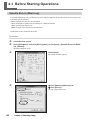
4-1 Before Starting Operations...................................................................66
Spindle Run-in (Warm-up)...........................................................................................................66
Detection of the Jig Location......................................................................................................67
4-2 Preparation for and Performing Cutting...................................................70
Usable Workpieces..........................................................................................................................70
Names of Jigs....................................................................................................................................71
Sub Clamp Selection......................................................................................................................71
Cuttable Area....................................................................................................................................72
Misalignment of centers of workpiece height and A axis (Offset).................................73
Mounting the Workpiece ............................................................................................................74
Installing a Tool................................................................................................................................76
Tool Length Measurement...........................................................................................................77
Starting Cutting...............................................................................................................................79
4-3 Override................................................................................................80
What's an Override?........................................................................................................................80
How to Set Overrides.....................................................................................................................80
4-4 Fine-Tuning the Origins.........................................................................81
Method for Fine-Tuning the Origins.........................................................................................81
Determining the Adjustment Value..........................................................................................82
Chapter 5 Appendix...........................................................................................83
5-1 Maintenance.........................................................................................84
Care and Maintenance of the Cutting Machine...................................................................84
Care for the Detection Pin and the Attachment for Detection.......................................85
Maintenance of the Spindle Unit...............................................................................................86
5-2 What to Do If.........................................................................................87
Initialization is not performed or initialization fails............................................................87
VPanel doesn't start correctly.....................................................................................................87
Operations are ignored.................................................................................................................87
The spindle doesn't rotate...........................................................................................................88
Abnormal cutting is performed.................................................................................................88
Jig detection failed.........................................................................................................................88
The feed rate or spindle speed is wrong.................................................................................88
The cutting results are not attractive.......................................................................................88
Installation is impossible..............................................................................................................88
Uninstalling the Driver..................................................................................................................89
The computer shut down.............................................................................................................90
4
Contents
5-3 Responding to an Error Message.........................................................91
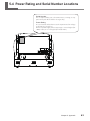
5-4 Power Rating and Serial Number Locations.........................................93
5-5 Expansion Connector Specification......................................................94
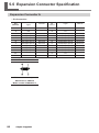
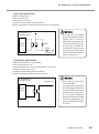
Expansion Connector A.................................................................................................................94
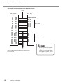
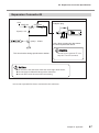
Expansion Connector B.................................................................................................................97
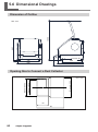
5-6 Dimensional Drawings..........................................................................98
Dimension of Outline.....................................................................................................................98
Opening Size to Connect a Dust Collector.............................................................................98
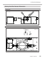
Rotary Axis/Tool Sensor Dimension.........................................................................................99
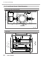
X-, Y- and Z-axis Travel / Table Dimension............................................................................ 100
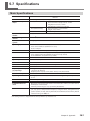
5-7 Specifications......................................................................................101
Main Specifications...................................................................................................................... 101
System Requirements for USB Connection......................................................................... 102
Company names and product names are trademarks or registered trademarks of their respective holders.
Copyright © 2009-2010 Roland DG Corporation
http://www.rolanddg.com/
5
To Ensure Safe Use
Improper handling or operation of this machine may result in injury or damage to property. Points
which must be observed to prevent such injury or damage are described as follows.
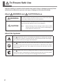
About
WARNING and
WARNING
CAUTION Notices
Used for instructions intended to alert the user to the risk of death or
severe injury should the unit be used improperly.
Used for instructions intended to alert the user to the risk of injury or
material damage should the unit be used improperly.
CAUTION
Note:
Material damage refers to damage or other adverse effects
caused with respect to the home and all its furnishings, as
well to domestic animals or pets.
About the Symbols
The
symbol alerts the user to important instructions or warnings. The specific
meaning of the symbol is determined by the design contained within the triangle.
The symbol at left means "danger of electrocution."
The
symbol alerts the user to items that must never be carried out (are
forbidden). The specific thing that must not be done is indicated by the design
contained within the circle. The symbol at left means the unit must never be
disassembled.
The
symbol alerts the user to things that must be carried out. The specific thing
that must be done is indicated by the design contained within the circle. The symbol
at left means the power-cord plug must be unplugged from the outlet.
6
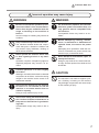
To Ensure Safe Use
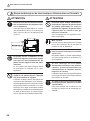
Incorrect operation may cause injury.
WARNING
Be sure to follow the operation procedures described in this documentation.
Never allow anyone unfamiliar with the
usage or handling of the machine to
touch it.
Incorrect usage or handling may lead to an
accident.
Keep children away from the machine.
The machine includes areas and components that pose a hazard to children and
may result in injury, blindness, choking, or
other serious accident.
Never operate the machine while tired
or after ingesting alcohol or any medication.
Operation requires unimpaired judgment.
Impaired judgment may result in an accident.
Conduct operations in a clean, brightly
lit location.
Working in a location that is dark or cluttered
may lead to an accident, such as becoming
caught in the machine as the result of an
inadvertent stumble.
Never use the machine for any purpose
for which it is not intended, or use the
machine in an undue manner that exceeds its capacity.
Doing so may result in injury or fire.
WARNING
For accessories (optional and consumable items, power cord, and the like), use
only genuine articles compatible with
this machine.
Incompatible items may lead to an accident.
Before attempting cleaning, maintenance, or attachment or detachment of
optional items, disconnect the power
cord.
Attempting such operations while the machine is connected to a power source may
result in injury or electrical shock.
Never attempt to disassemble, repair, or
modify the machine.
Doing so may result in fire, electrical shock,
or injury. Entrust repairs to a trained service
technician.
CAUTION
Never climb or lean on the machine.
The machine is not made to support a person. Climbing or leaning on the machine
may dislodge components and cause a slip
or fall, resulting in injury.
Never use a cutting tool that has become
dull. Perform frequent maintenance to
keep and use the machine in good working order.
Unreasonable usage may result in fire or
injury.
7
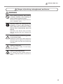
To Ensure Safe Use
This machine weighs 47 kg (104 lb.)
CAUTION
Unloading and emplacement are operations that must be performed by 2 persons or more.
Tasks that require undue effort when performed by a small number of persons may
result in physical injury. Also, if dropped,
such items may cause injury.
CAUTION
Install in a location that is level and
stable.
Installation in an unsuitable location may
cause an accident, including a fall or tip
over.
The cutting waste or workpiece may catch fire or pose a health hazard.
WARNING
Never attempt to cut magnesium or any
other such flammable material.
Fire may occur during cutting.
Keep open flame away from the work
area.
Cutting waste may ignite. Powdered material is extremely flammable, and even metal
material may catch fire.
When using a vacuum cleaner to take
up cutting waste, exercise caution to
prevent fire or dust explosion.
Taking up fine cuttings using an ordinary
vacuum cleaner may cause danger of fire
or explosion. Check with the manufacturer
of the vacuum cleaner. When the safety of
use cannot be determined, clean using a
brush or the like, without using the vacuum
cleaner.
8
CAUTION
Wear dust goggles and a mask. Wash
away any cutting waste remaining on
the hands.
Accidentally swallowing or inhaling cutting
waste may be hazardous to the health.
To Ensure Safe Use
Danger of pinching, entanglement, and burns.
WARNING
Never attempt operation while wearing
a necktie, necklace, loose clothing, or
gloves. Bind long hair securely.
Such items may become caught in the machine, resulting in injury.
Securely fasten the cutting tool and
workpiece in place. After securing in
place, make sure no wrenches or other
articles have inadvertently been left
behind.
Otherwise such articles may be thrown
from the machine with force, posing a risk
of injury.
Exercise caution to avoid being pinched
or becoming caught.
Inadvertent contact with certain areas may
cause the hand or fingers to be pinched or
become caught. Use care when performing
operations.
Caution: cutting tool.
The cutting tool is sharp. To avoid injury,
exercise caution.
Caution: high temperatures.
The cutting tool and spindle motor become hot. Exercise caution to avoid fire or
burns.
9
To Ensure Safe Use
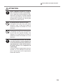
Danger of electrical short, shock, electrocution, or fire
WARNING
Connect to an electrical outlet that complies
with this machine’s ratings (for voltage and
frequency).
Provide a power supply whose amperage
is 2.8 A or higher (for 100 to 120 V) or 1.2 A
or higher (for 220 to 240 V).
Ratings
Never use out of doors or in any location where exposure to water or high
humidity may occur. Never touch with
wet hands.
Doing so may result in fire or electrical
shock.
Never allow any foreign object to get
inside. Never expose to liquid spills.
Inserting objects such as coins or matches
or allowing beverages to be spilled into the
ventilation ports may result in fire or electrical shock. If anything gets inside, immediately disconnect the power cord and contact
your authorized Roland DG Corp. dealer.
WARNING
Never place any flammable object nearby.
Never use a combustible aerosol spray
nearby. Never use in any location where
gases can accumulate.
Combustion or explosion may be a danger.
Handle the power cord, plug, and electrical outlet correctly and with care. Never
use any article that is damaged.
Using a damaged article may result in fire
or electrical shock.
When using an extension cord or power
strip, use one that adequately satisfies
the machine’s ratings (for voltage, frequency, and current).
Use of multiple electrical loads on a single
electrical outlet or of a lengthy extension
cord may cause fire.
When the machine will be out of use
for a prolonged period, disconnect the
power cord.
This can prevent accidents in the event of
current leakage or unintended startup.
Connect to ground.
This can prevent fire or electrical shock due
to current leakage in the event of malfunction.
Position so that the power plug is within
immediate reach at all times.
This is to enable quick disconnection of the
power plug in the event of an emergency. Install the machine next to an electrical outlet.
Also, provide enough empty space to allow
immediate access to the electrical outlet.
Never use cutting oil.
This machine is not designed for the flow of
cutting oil. Oil may get inside the machine
and cause fire or electrical shock.
10
To Ensure Safe Use
WARNING
Never use a pneumatic blower.
This machine is not compatible with a
pneumatic blower. Cutting waste may get
inside the machine and cause fire or electrical shock.
If sparking, smoke, burning odor, unusual
sound, or abnormal operation occurs, immediately unplug the power cord. Never
use if any component is damaged.
Continuing to use the machine may result in
fire, electrical shock, or injury. Contact your
authorized Roland DG Corp. dealer.
11
To Ensure Safe Use
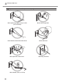
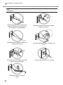
Important notes about the power cord, plug, and electrical outlet
Never place any object on top or subject to damage.
Never allow to get wet.
Never bend or twist with undue force.
Never make hot.
Never pull with undue force.
Never bundle, bind, or roll up.
12
Dust may cause fire.
To Ensure Safe Use
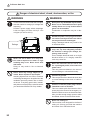
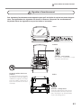
Warning Labels
Warning labels are affixed to make areas of danger immediately clear. The meanings of these
labels are as follows. Be sure to heed their warnings.
Also, never remove the labels or allow them to become obscured.
Top
Front / Inside
Caution: Sharp Tool
Inadvertent contact may
cause injury.
Never use a pneumatic
blower.
This machine is not compatible with a pneumatic blower.
Cutting waste may get inside
the machine and cause fire or
electrical shock.
Rear
Caution: High Voltage
Cover removal may pose hazard of
shock or electrocution due to high
voltage
13
Pour utiliser en toute sécurité
La manipulation ou l'utilisation inadéquates de cet appareil peuvent causer des blessures ou
des dommages matériels. Les précautions à prendre pour prévenir les blessures ou les dommages sont décrites ci-dessous.
Avis sur les avertissements
ATTENTION
Utilisé pour avertir l'utilisateur d'un risque de décès ou de blessure
grave en cas de mauvaise utilisation de l'appareil.
Utilisé pour avertir l'utilisateur d'un risque de blessure ou de
dommage matériel en cas de mauvaise utilisation de l'appareil.
PRUDENCE
* Par dommage matériel, il est entendu dommage ou tout autre
effet indésirable sur la maison, tous les meubles et même les
animaux domestiques.
À propos des symboles
Le symbole
attire l'attention de l'utilisateur sur les instructions importantes
ou les avertissements. Le sens précis du symbole est déterminé par le dessin à
l'intérieur du triangle. Le symbole à gauche signifie "danger d'électrocution."
Le symbole
avertit l'utilisateur de ce qu'il ne doit pas faire, ce qui est interdit. La
chose spécifique à ne pas faire est indiquée par le dessin à l'intérieur du cercle. Le
symbole à gauche signifie que l'appareil ne doit jamais être démonté.
Le symbole
prévient l'utilisateur sur ce qu'il doit faire. La chose spécifique à faire
est indiquée par le dessin à l'intérieur du cercle. Le symbole à gauche signifie que le
fil électrique doit être débranché de la prise.
14
Pour utiliser en toute sécurité
L’utilisation incorrecte peut causer des blessures
ATTENTION
S’assurer de suivre les procédures
d’utilisation décrites dans la documentation. Ne jamais permettre à quiconque
ne connaît pas le fonctionnement ou la
manutention de l’appareil de le toucher.
L’utilisation ou la manutention incorrectes
peuvent causer un accident.
Garder les enfants loin de l’appareil.
L’appareil comporte des zones et des composants qui présentent un danger pour les
enfants et qui pourraient causer des blessures, la cécité, la suffocation ou d’autres
accidents graves.
ATTENTION
Ne jamais utiliser un outil de coupe
émoussé. Procéder fréquemment aux
travaux d’entretien pour garder l’appareil
en bon état de fonctionnement.
L’usage abusif peut causer un incendie ou
des blessures.
Utiliser uniquement des accessoires
d’origine (accessoires en option, articles
consommables, câble d’alimentation et
autres articles semblables), compatibles
avec l’appareil.
Les articles incompatibles risquent de
causer des accidents.
Ne jamais faire fonctionner l’appareil
après avoir consommé de l’alcool ou
des médicaments, ou dans un état de
fatigue.
L’utilisation de l’appareil exige un jugement
sans faille. L’utilisation avec les facultés affaiblies pourrait entraîner un accident.
Débrancher le câble d’alimentation avant
de procéder au nettoyage ou à l’entretien
de l’appareil, et avant d’y fixer ou d’en
retirer des accessoires en option.
Tenter ces opérations pendant que l’appareil
est branché à une source d’alimentation
peut causer des blessures ou un choc
électrique.
Utiliser l’appareil dans un endroit propre
et bien éclairé.
Travailler dans un endroit sombre ou encombré peut causer un accident; l’utilisateur
risque, par exemple, de trébucher malencontreusement et d’être coincé par une
partie de l’appareil.
Ne jamais tenter de démonter, de réparer
ou de modifier l’appareil.
Le non-respect de cette consigne risque de
provoquer un incendie, un choc électrique
ou des blessures. Confier les réparations à
un technicien ayant la formation requise.
Ne jamais utiliser l’appareil à des fins
autres que celles pour lesquelles il est
conçu. Ne jamais l’utiliser de manière
abusive ou d’une manière qui dépasse
sa capacité.
Le non-respect de cette consigne peut
causer des blessures ou un incendie.
PRUDENCE
Ne jamais grimper ni s’appuyer sur
la machine.
La machine n’est pas conçue pour supporter le poids d’une personne. Grimper
ou s’appuyer sur la machine peut déplacer des éléments et causer un faux
pas ou une chute, ce qui causerait des
blessures.
15
Pour utiliser en toute sécurité
Le poids de cet appareil est de 47 kg (104 lb.)
PRUDENCE
Le déchargement et la mise en place
doivent être faits par au moins 2 personnes.
Les tâches qui exigent un effort trop grand
si elles sont exécutées par un petit nombre
de personnes peuvent être cause de blessures. La chute d’articles très lourds peut
aussi causer des blessures.
PRUDENCE
Installer l’appareil à un endroit stable
et plat.
Installer l’appareil à un endroit inapproprié
peut provoquer un accident grave comme
le renversement ou la chute.
Les débris de coupe peuvent s ’enflammer ou présenter un risque pour la santé.
ATTENTION
Ne jamais tenter de couper du magnésium ni aucun autre matériau inflammable.
Un incendie pourrait se produire pendant
la coupe.
Ne pas approcher une flamme nue de
l’espace de travail.
Les rognures de coupe peuvent s’enflammer.
Les matériaux pulvérisés sont extrêmement inflammables et même le métal peut
s’enflammer.
Si un aspirateur est utilisé pour ramasser
les rognures de coupe, faire preuve
de prudence pour empêcher que la
poussière s’enflamme ou explose.
Ramasser des rognures fines à l’aide d’un
aspirateur ordinaire peut créer un risque
d’incendie ou d’explosion. Vérifier auprès
du fabricant de l’aspirateur. Dans les cas
où il est impossible de déterminer si un
aspirateur peut être utilisé sans danger, se
servir d’une brosse ou d’un article semblable
plutôt que d’un aspirateur.
16
PRUDENCE
Porter des lunettes de protection et un
masque. Rincer toutes les rognures de
coupe qui pourraient rester collées aux
mains.
Avaler ou respirer accidentellement des
rognures de coupe peut être dangereux
pour la santé.
Pour utiliser en toute sécurité
Certains éléments peuvent présenter un risque de
pincement, d’emmêlement, de brûlure ou d’autres dangers.
ATTENTION
Ne jamais faire fonctionner l’appareil si
on porte une cravate, un collier ou des
vêtements amples. Bien attacher les
cheveux longs.
Ces vêtements ou ces objets peuvent être
coincés dans l’appareil, ce qui causerait
des blessures.
Fixer solidement l’outil de coupe et la
pièce à travailler. Une fois qu’ils sont
fixés solidement, s’assurer qu’aucun
outil ni aucun autre objet n’a été laissé
en place.
Si tel était le cas, ces objets pourraient être
projetés avec force hors de l’appareil et
causer des blessures.
Faire preuve de prudence pour éviter
l’écrasement ou le coincement.
La main ou les doigts peuvent être écrasés
ou coincés s’ils entrent en contact avec
certaines surfaces par inadvertance. Faire
preuve de prudence pendant l’utilisation
de l’appareil.
Attention : outil de coupe.
L’outil de coupe est acéré. Faire preuve de
prudence pour éviter les blessures.
Attention : températures élevées.
L’outil de coupe et le moteur chauffent. Faire
preuve de prudence pour éviter un incendie
ou des brûlures.
17
Pour utiliser en toute sécurité
Risque de décharge ou de choc électrique, d’électrocution ou d’incendie
ATTENTION
Brancher à une prise électrique conforme
aux caractéristiques de cet appareil (tension et fréquence).
Il faut prévoir une alimentation en courant
dont l'intensité est de 2.8 A ou plus (pour
100 à 120 V) ou de 1.2 A ou plus (pour 220
à 240 V).
ATTENTION
Ne jamais placer d’objet inflammable à
proximité de l’appareil. Ne jamais utiliser
de produit inflammable en aérosol à
proximité de l’appareil. Ne jamais utiliser
l’appareil dans un endroit où des gaz
peuvent s’accumuler.
Une combustion ou une explosion pourraient se produire.
Mise à la terre.
La mise à la terre peut prévenir un incendie
ou un choc électrique dus à une fuite de
courant en cas de défaillance.
Ne jamais utiliser à l'extérieur ni à un
endroit où l'appareil risque d'être exposé
à de l'eau ou à une humidité élevée. Ne
jamais toucher l'appareil avec des mains
mouillées.
Le non-respect de cette consigne risque
de provoquer un incendie ou un choc
électrique.
Ne jamais insérer d’objet étranger dans
l’appareil. Ne jamais exposer l’appareil
aux déversements de liquides.
L’insertion d’objets comme des pièces de
monnaie ou des allumettes, ou le déversement de liquides dans les orifices de ventilation peuvent causer un incendie ou un choc
électrique. Si un objet ou du liquide s’infiltre
dans l’appareil, débrancher immédiatement
le câble d’alimentation et communiquer
avec le représentant Roland DG autorisé.
18
Manipuler le câble d’alimentation, la
fiche et la prise électrique correctement
et avec soin.
Ne jamais utiliser un article endommagé,
car cela pourrait causer un incendie ou un
choc électrique.
Si une rallonge ou une bande
d’alimentation électrique sont utilisées,
s’assurer qu’elles correspondent aux
caractéristiques de l’appareil (tension,
fréquence et courant).
L’utilisation de plusieurs charges électriques
sur une prise unique ou une longue rallonge
peut causer un incendie.
Si l’appareil doit rester inutilisé pendant
une longue période, débrancher le câble
d’alimentation.
Cela peut prévenir les accidents en cas
de fuite de courant ou de démarrage accidentel.
Pour utiliser en toute sécurité
ATTENTION
Placer l’appareil de façon à ce que la
fiche soit facile d’accès en tout temps.
Ainsi, l’appareil pourra être débranché rapidement en cas d’urgence. Installer l’appareil
près d’une prise électrique. En outre, prévoir
suffisamment d’espace pour que la prise
électrique soit facile d’accès.
Ne jamais utiliser d’huile de coupe.
Cet appareil n’est pas conçu pour traiter
l’huile de coupe. L’huile peut s’infiltrer à
l’intérieur et causer un incendie ou un choc
électrique.
Ne jamais utiliser d’air sous pression.
Cet appareil n’est pas conçu pour être nettoyé à l’aide d’un appareil soufflant. Des
rognures de coupe peuvent s’infiltrer à
l’intérieur et causer un incendie ou un choc
électrique.
S’il se produit des étincelles, de la fumée,
une odeur de brûlé, un bruit inhabituel ou
un fonctionnement anormal, débrancher
immédiatement le câble d’alimentation.
Ne jamais utiliser si un composant est
endommagé.
Continuer à utiliser l’appareil peut causer un
incendie, un choc électrique ou des blessures. Communiquer avec le représentant
Roland DG Autorisé.
19
Pour utiliser en toute sécurité
Remarques importantes à propos du câble d'alimentation, de la fiche et de la prise
électrique
Ne jamais déposer aucun objet sur le
câble, sur la fiche ou sur la prise car
cela risque de les endommager.
Ne jamais laisser l'eau toucher le câble,
la fiche ou la prise.
Ne jamais plier ni tordre le câble avec
une force excessive.
Ne jamais chauffer le câble, la fiche ou la
prise.
Ne jamais tirer sur le câble ou la fiche
avec une force excessive.
La poussière peut causer un incendie.
Ne jamais plier ni enrouler le
câble.
20
Pour utiliser en toute sécurité
Vignettes d'avertissement
Des vignettes d'avertissement sont apposées pour qu'il soit facile de repérer les zones dangereuses. La signification des vignettes est donnée ci-dessous. Respecter les avertissements.
Ne jamais retirer les vignettes et ne pas les laisser s'encrasser.
Avant
Intérieur
Attention : outil coupant
Un contact imprudent risque
d’entraîner une blessure.
Ne jamais utiliser d’air sous
pression.
Cet appareil n’est pas conçu pour
être nettoyé à l’aide d’un appareil
soufflant. Des rognures de coupe
peuvent s’infiltrer à l’intérieur et
causer un incendie ou un choc
électrique.
Arrière
Attention : voltage élevé
Il peut être dangereux de retirer le couvercle puisqu’il y aurait des risques de
chocs électriques ou d’électrocution
à cause du voltage élevé.
21
Important Notes on Handling and Use
This machine is a precision device. To ensure the full performance of this machine, be sure to
observe the following important points. Failure to observe these points may not only result in
loss of performance, but may also cause malfunction or breakdown.
This machine is a precision device.
Handle carefully, and never subject the machine to impact or excessive force.
Diligently keep clean of cutting waste.
Use within the range of specifications.
Never attempt to move the spindle head and rotary axis by hand with undue force.
Never needlessly touch anywhere inside the machine except for locations specified in this
manual.
Install in a suitable location.
Install in a location that meets the specified conditions for temperature, relative humidity,
and the like.
Install
in a quiet, stable location offering good operating conditions.
Never
install
in out doors.
Never
use
the
machine in an environment where silicone substances (oil, grease, spray, etc.)
are present. Doing so may cause poor switch contact.
This machine becomes hot.
Never cover the ventilation holes with cloth, tape, or anything else.
Install in a well-ventilated location.
This machine is exclusively for cutting modeling wax and zirconia.
Never cut any material other than modeling wax and zirconia.
About Tools
The tip of the tool is breakable. Handle with care, being careful not to drop it.
22
About the Documentation for This Machine
Documentation Included with the Machine
The following documentation is included with the machine.
User's Manual (this manual)
This contains important notes for ensuring safe use, as well as detailed information on how to install and
operate the machine and install and set up the included programs.
Be sure to read it first.
VPanel Online Help (electronic-format manual)
These are user's manual that you view on a computer screen. Installing the respective programs makes these
available for viewing.
P. 42, "Installing and Setting Up VPanel"
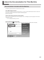
How to View the VPanel Online Help
From the [Start] menu(
), click [All Programs], then [Roland VPanel for DWX-30]. Then click [HELP].
23
24
Chapter 1
Getting Started
1-1 Machine Highlights................................................................26
What You Can Do with This Machine.........................................26
1-2 Part Names and Functions....................................................27
Front and Interior........................................................................27
Side............................................................................................28
VPanel........................................................................................29
Handy Panel and Built-in Panel . ...............................................30
25
1-1 Machine Highlights
What You Can Do with This Machine
A Machine Exclusively for Creating Artificial Teeth and Tooth Models
This machine is exclusively for making artificial teeth and tooth models. It is used to produce artificial teeth
and tooth models using modeling wax or zirconia.
Installing and setting up the exclusive programs on your computer and connecting the machine to the computer enables you to create high-quality artificial teeth and tooth models in much less time than it would
take to fashion them by hand.
Includes Special Jig As Standard Features
The jig needed to make artificial teeth and tooth models is included with the machine as standard equipment.
Easy-operation VPanel and Handy Panel
VPanel, which you use once installed and set up on a computer, is the main operation panel for the machine,
achieving ease of use with a large display area. Using VPanel, not only can you move the tool and switch the
spindle on and off, you can also perform automatic detection of the location of the installed jig, make the
settings for the origin points, and more. You can also operate the machine while watching the workpiece
from close up by using the handy panel, which is capable of a subset of operations for tool movement and
spindle on/off control.
Equipped with a High-performance Tool Sensor
The machine is equipped with the high-performance tool sensor needed to achieve high-precision cutting.
Detection of the jig location and setting the reference position for cutting can be accomplished accurately
thanks to this high-performance tool sensor.
26
Chapter 1 Getting Started
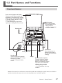
1-2 Part Names and Functions
Front and Interior
Front covers (upper and lower)
The front covers open upward and
downward. To ensure safety, opening
either of these covers during cutting
or spindle rotation causes an emergency stop to occur.
P. 53, "Emergency Stop Due to
Opening or Closing the Front Cover"
Built-in panel
This is the operation
panel installed on the
cutting machine.
P. 30, "Handy Panel
and Built-in Panel"
Spindle head*
Rotary axis unit
Handy panel
This is a hand-held operation
panel connected to the cutting
machine by a cable.
P. 62, "Using the Handy
Panel"
Clamp
Table
Tool sensor
This is the sensor for
detecting the length of
the tool and the location
of the jig.
Dust collection capsule
The dust collection capsule
prevents cutting dust from
blowing out and helps suction.
The cover can be detached.
* Detach the cover when
detecting the jig location.
P. 67, "Detection of the Jig
Location"
*NOTE: In this manual, the mechanisms around the spindle unit, including the spindle motor, are called the
“spindle head.” Also, the rotary-axis area inside the spindle unit is called the “spindle.”
Chapter 1 Getting Started
27
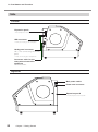
1-2 Part Names and Functions
Side
Left side
Expansion port A
P. 94, “Expansion Connector A”
USB connector
P. 40, “Connecting to the Computer”
Handy-panel connector
This is for connecting the handy
panel.
P. 39, “Connecting the Handy Panel”
Connector cable for the
rotary axis unit and other
equipment
Never detach this.
Right side
Main power switch
Power-cord connector
Expansion port B
P. 97, “Expansion Connector B”
28
Chapter 1 Getting Started
1-2 Part Names and Functions
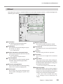
VPanel
Operation of the machine is controlled from the screen of your computer. VPanel is a dedicated program for
controlling the machine.
Coordinates
This displays the present tool location.
P. 55, "Viewing the Tool Location"
Feed buttons
These perform movement along the respective axes (X, Y, Z, and A).
P. 54, "Manual Feed"
Specific-destination movement button
You use this to make the tool move directly
to a specific position.
P. 57, "Moving to a Specific Position"
Override buttons
These change the speed of spindle rotation
and other aspects of cutting operations.
P. 80, "Override"
Base-point setting buttons
These set the base points used during cutting,
such as the X- and Y-axis origin points.
Spindle speed
This displays the present rotating speed
of the spindle. Changing the speed is also
possible.
Spindle-rotation button
This switches spindle rotation on and off.
P. 58, "Starting and Stopping Spindle Rotation"
Tool feed rate
This displays the present speed of tool movement .
Jig button
This detects the jig and sets the origin points.
Tool button
This measures the length of the mounted
tool.
Setup button
You use this at times such as when making settings to fine-tune the operation of the machine.
For detailed information about the setting, refer
to the online help of VPanel.
P. 23, "How to View the VPanel Online Help"
Preference button
You use this at times such as when setting the
measurement unit used to display coordinates
in VPanel. For detailed information about the
setting, refer to the online help of VPanel.
P. 23, "How to View the VPanel Online Help,"
p. 56, "Changing the Unit of Measurement for
Display"
Chapter 1 Getting Started
29
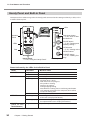
1-2 Part Names and Functions
Handy Panel and Built-in Panel
You operate this machine using either the handy panel connected to the cutting machine by a cable, or the
machine's built-in panel.
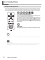
LEDs
Sub power button
P. 50, "How to Start
the Machine"
Operation
buttons
PAUSE button
P. 59, "Pausing and
Quitting Cutting"
LEDs
VIEW button
P. 57, "Moving to the
VIEW Position"
Dial
Handy panel
P. 62, "Using the Handy Panel"
Built-in panel
CANCEL button
P. 61, "Quitting Cutting"
Status Indicated by the LEDs for the Built-in Panel
Name
POWER
READY
ERROR
LED state
Lighted
Dark
Lighted
Flashing
Dark
Flashing slowly
Flashing rapidly
PAUSE
(next to the
PAUSE button)
30
Lighted
Chapter 1 Getting Started
Machine status
The main power is on.
The main power is off.
The sub power is on.
Initializing.
The front cover is open.
Tool movement is in progress.
The spindle is rotating.
Cutting is in progress.
During stopping cutting
Note: When the cutting data is sent during initialization
and stopping cutting from the computer, the machine
accepts no cutting data.
The sub power is off.
A warning (nonfatal error) has occurred. (A description
of the error is displayed in VPanel.)
An error resulting in an emergency stop has occurred. (A
description of the error is displayed in VPanel.)
Operation is paused.
Chapter 2
Installation and Setup
2-1 Checking the Included Items.................................................32
2-2 Installation..............................................................................34
About Emplacement and Installation..........................................34
Installation Environment.............................................................34
Unpacking...................................................................................36
Installing the Dust Tray...............................................................37
About a Dust Collector................................................................38
How to Connect the Dust Collection Hoses...............................38
2-3 Cable Connections................................................................39
Connecting the Handy Panel......................................................39
Connecting the Power Cord.......................................................39
Connecting to the Computer......................................................40
2-4 Installing and Setting Up the Software..................................41
System Requirements................................................................41
The Software You Can Install and Set Up..................................41
Installing the Windows-based Driver..........................................41
Installing and Setting Up VPanel................................................42
2-5 Connecting Multiple Units......................................................44
How to Connect Multiple Units...................................................44
Select a machine to use.............................................................47
31
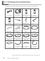
2-1 Checking the Included Items
The following items are included with the machine. Make sure they are all present and accounted for.
Collet
(diameter 3.175 mm)
(1)
Collet
(diameter 4.0mm)(1)
Power cord(1)
Handy panel(1)
Collet
(diameter 3.0mm) (1)
Hexagonal driver(1)
Detection pin (1)
Attachment for detection (1)
Cap* (1)
Spacer (1)
Clamp C-1 for block
workpiece (1)
Clamp C-2 for block
workpiece (1)
Clamp D-1 for block
workpiece (1)
Clamp D-2 for block
workpiece (1)
Dust tray (1)
Dust collection hose
A (1)
Dust collection hose
B (1)
Dust collection hose
C (1)
Spanner (10 mm,
Hexagonal wrench (1)
17mm) (one for each)
*Note: The cutting machine is shipped from the factory with these parts installed on it.
32
Chapter 2 Installation and Setup
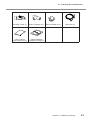
2-1 Checking the Included Items
Cleaning nozzle (1)
Branch adapter A (1)
User's manual
(this document) (1)
Roland Software
Package CD-ROM (1)
Branch adapter B (1)
USB cable (1)
Chapter 2 Installation and Setup
33
2-2 Installation
About Emplacement and Installation
WARNING
Unloading and emplacement are operations that must be performed by
2 persons or more.
Tasks that require undue effort when performed by a small number of persons
may result in physical injury. Also, if dropped, such items may cause injury.
The weight of the machine alone is 47 kg (104 lb.). Perform unloading and emplacement with care.
Installation Environment
Install in a quiet, stable location offering good operating conditions. An unsuitable location can cause accident,
fire, faulty operation, or breakdown.
WARNING
Install in a location that is level and stable.
Installation in an unsuitable location may cause an accident, including a fall
or tip over.
WARNING
Never install in a location exposed to open flame.
Cutting waste may ignite. Powdered material is extremely flammable, and even
metal material may catch fire.
WARNING
Never install close to any flammable object or in a gas-filled location.
Combustion or explosion may be a danger.
WARNING
Never install outdoors or in any location where exposure to water or high
humidity may occur.
Doing so may result in fire or electrical shock.
WARNING
Position so that the power plug is within immediate reach at all times.
This is to enable quick disconnection of the power plug in the event of an emergency. Install the machine next to an electrical outlet. Also, provide enough
empty space to allow immediate access to the electrical outlet.
Never locate in a location subject to wide fluctuations in temperature or humidity.
Never install in a location subject to shaking or vibration.
Never install in a location where the floor is tilted, unlevel, or unstable.
Never install in a dusty or dirty location, or outdoors.
Never install in a location exposed to direct sunlight or near air-conditioning or heating equipment.
Never install in a location exposed to considerable electrical or magnetic noise, or other forms of electromagnetic energy.
Never install in an environment where silicone substances (oil, grease, spray, etc.) are present.
34
Chapter 2 Installation and Setup
2-2 Installation
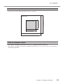
Installation Space
Ensure that at least the following amount of space is available.
2.0 m (80 in.)
Installation space
1.0 m (40 in.)
Work space
1.0 m (40 in.)
2.0 m (80 in.)
About the installation location
The height of installation should be 0.6 m (23.7 in.) or higher above the work floor.
This machine is desktop type. Install in a location that allows easy access to areas such as the main power
switch during operation.
Chapter 2 Installation and Setup
35
2-2 Installation
Unpacking
Retaining materials are attached to protect the machine from vibration during shipment. When installation is
complete, remove these and store in the specified locations.
Remove all retaining materials. Any that remain may cause faulty operation or breakdown when the power
is switched on.
The retaining materials are required when moving the machine to a different location. Store them carefully
so that they do not get misplaced.
WARNING
Carry out these operations before you connect the power cord.
Inadvertent powerup may result in pinched hands or other injury.
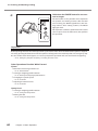
Removing the retainers
Remove the fixing tape on
the back of the machine.
Fixing tape
Retainer C
Remove.
Retainer B
Retainer A
Cap screws
This is also used to store the retainers.
36
Chapter 2 Installation and Setup
Make sure the power cord is
unplugged, and remove the
retainer A, B, and C, and the
fixing tape.
2-2 Installation
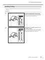
Storing the retainers
You can attach retainers A and
B at the location shown in the
figure, and store the hexagonal
wrench (used when replacing
the spindle unit). Store retainer
C so that it will not become
misplaced, because it is also
needed when relocating the
machine.
Cap screws
Use items for
fastening.
Retainer A, B
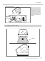
Installing the Dust Tray
You use the dust tray with it placed between the rubber feet on the bottom of the machine.
Dust tray
Chapter 2 Installation and Setup
37
2-2 Installation
About a Dust Collector
You can install a dust collector to collect cutting dust to the machine. You need to prepare a dust collector
separately. When you use the machine with a dust collector installed, you should clean the dust collector
regularly.
Static pressure: Prepare a dust collector with 1 kPa or more.
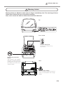
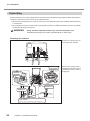
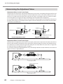
How to Connect the Dust Collection Hoses
Connect the supplied hose and branch adaptor as shown in the figure.
*You need to prepare a dust collector separately.
P. 98, "Opening Size to Connect a Dust Collector"
Cap
Keep the cap on during cutting. Otherwise, cutting dust will fly off.
Dust collector
Have this ready separately.
Dust collection hose A
Dust collection hose C
Dust collection hose B
Branch adapter A
38
Chapter 2 Installation and Setup
Branch adapter B
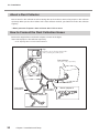
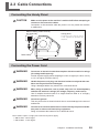
2-3 Cable Connections
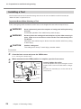
Connecting the Handy Panel
CAUTION
Left side
Make sure the power to the machine is switched off before attempting to
connect or disconnect the cables.
Connection or disconnection while the power is on may cause the machine
to malfunction.
When inserting, orient correctly
and insert fully.
Handy panel
Connecting the handy panel
is not required to operate the
machine.
Cable clamp
Connecting the Power Cord
WARNING
Connect to an electrical outlet that complies with this machine's ratings
(for voltage and frequency).
Provide a power supply whose amperage is 2.8 A or higher (for 100 to 120 V)
or 1.2 A or higher (for 220 to 240 V).
WARNING
Handle the power cord, plug, and electrical outlet correctly and with care.
Never use any article that is damaged.
Using a damaged article may result in fire or electrical shock.
WARNING
When using an extension cord or power strip, use one that adequately
satisfies the machine's ratings (for voltage, frequency, and current).
Use of multiple electrical loads on a single electrical outlet or of a lengthy
extension cord may cause fire.
WARNING
Connect to ground.
This can prevent fire or electrical shock due to current leakage in the event of
malfunction.
WARNING
Connect to an electrical outlet. Never connect directly to a power distribution panel or other such fixed wiring equipment.
Doing so increases the hazard of fire or electrical shock.
This machine requires a single-phase commercial power supply.
100 to 120 V: 2.8A or higher
220 to 240 V: 1.2 A or higher
Chapter 2 Installation and Setup
39
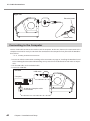
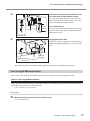
2-3 Cable Connections
Right side
Electrical outlet
Power cable
Connecting to the Computer
You use a USB cable to connect the machine and the computer. At this time, however, the connection to the
computer must not be made yet. You make the connection to the computer when you install the Windowsbased driver.
P. 41, "Installing the Windows-based Driver"
Be sure to make the connection according to the instructions on page 41, "Installing the Windows-based
Driver." Making the connection without doing so may cause driver installation to fail and make use impossible.
For the USB cable, use the included cable.
Never use a USB hub.
Left side
USB cable
Computer
At this time, keep the cable
unconnected
40
Chapter 2 Installation and Setup
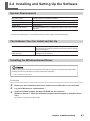
2-4 Installing and Setting Up the Software
System Requirements
Operating system
CPU
Memory
Optical drive
Video card and monitor
Windows XP/Vista/7(32,64 bit edition)
The minimum required CPU for the operating system
The minimum amount of required RAM for the operating system
CD-ROM drive
At least 256 colors with a resolution of 1,024 x 768 or more recommended)
For the latest information, see the Roland DG Corp. website (http://www.rolanddg.com).
The Software You Can Install and Set Up
VPanel for DWX-30
Windows driver
(DWX-30 driver)
This is a dedicated program for controlling the modeling machine.
You operate the modeling machine and make various settings
using this program.
This is a Windows-based driver required for sending data from a
computer to the machine.
Installing the Windows-based Driver
Keep machine and the computer unconnected until you carry out this installation operation. Failure
to follow the correct procedure may make installation impossible.
P. 88, "Installation is impossible"
Procedure
Before you start installation and setup, make sure the USB cable is not connected.
Log on to Windows as “Administrator.”
Insert the Roland Software Package CD-ROM into the computer.
(Windows Vista or 7 : When the automatic playback window appears, click [Run menu.
exe].)
The setup menu appears automatically.
Chapter 2 Installation and Setup
41
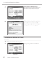
2-4 Installing and Setting Up the Software
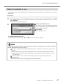
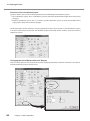
Click [Install] of "Windows Driver".
An Installation and Setup Guide matched to the
basic software on your computer is displayed.
Setup menu
Follow the instructions in the Installation
and Setup Guide to finish installing.
After installation is completed, the window for the
setup menu appears again. Go on to "Installing and
Setting Up VPanel" on the following page.
Installation and Setup Guide
Installing and Setting Up VPanel
Procedure
Display the window for the setup menu.
Click [Install] of "VPanel for DWX-30."
Setup menu
42
Chapter 2 Installation and Setup
2-4 Installing and Setting Up the Software
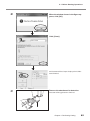
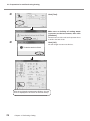
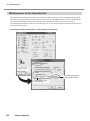
When the screen shown in the figure appears, click [Next], then follow the prompts to
install and set up the program.
(Windows Vista or 7: When the [User Account Control] appears, click [Allow] or [Yes].)
When all installation finishes, click
on the setup menu.
Remove the CD-ROM from the CD-ROM drive.
This completes installation of VPanel.
Chapter 2 Installation and Setup
43
2-5 Connecting Multiple Units
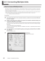
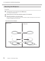
How to Connect Multiple Units
Up to four machines can be connected to a single computer. When more than one machine is connected,
each machine needs to be identified on VPanel. An ID (A, B, C, and D) must be assigned to each machine to
make the setting for each machine.
In the initial setting, "A" is assigned as an ID of the machine. This section describes how to set up the IDs of the
second machine and after he setting assuming that the ID of the first machine is set up as “A”.
P. 41, "Installing the Windows-based Driver"
Procedure
Turn off the main power of the connected machine, and then disconnect the USB cable
from the computer.
Switch on the main power and the sub power of the machine connected newly, and
connect the USB cable to a computer.
Make the connection setting of the machines one by one. Be sure to connect only the machine of which
the setting is made. If you connect the machines with a same ID at the same time, the computer might
shut down.
For the USB cable, use the included cable.
Be sure to refrain from using a USB hub. If a USB hub is used, there is a possibility that the machine
cannot be connected.
Go to [Start Menu], and click [All Programs] (or [Program]) - [Roland VPanel for DWX30] - [VPanel].
The VPanel program starts.
44
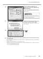
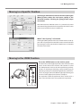
Click [Setup].
The [Setup] window appears.
Chapter 2 Installation and Setup
2-5 Connecting Multiple Units
Click the [Modeling Machine] tab.
Select any unused ID in [Machine ID],
and press [Set ID].
Assign an ID to identify the machine on VPanel.
Since A is assigned to the first machine, be sure to
select B, C, or D.
Do not assign a same ID. If you connect the
machines with the same ID at the same time,
the computer might shut down.
Read the message displayed on the screen
as shown in the left, and click [OK].
When the message, "Operation is complete," appears, click [OK].
Exit VPanel.
Click
.
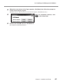
Once switch off the power of the machine, and then switch on the main power and the
sub power again.
The assigned ID is recognized by the machine. If the ID is assigned for the first time, a corresponding
driver is required.
Windows 7: The required driver is automatically created.
Windows Vista/XP: A message to prompt the user to install the Windows driver is displayed. Install the
driver in accordance with the message.
P.41, "Installing the Windows-based Driver"
Chapter 2 Installation and Setup
45
2-5 Connecting Multiple Units
Restart VPanel.
When you connect the third and fourth machines, turn off the power of all the machines, disconnect the USB cables from the computer, and exit "VPanel."
Repeat the above steps to .
After VPanel is restarted, the assigned ID is enabled,
You can connect all the machines of which the setting has been done to the computer by USB cables. At this
point, if you connect the machines with a same ID at the same time, the computer might shut down.
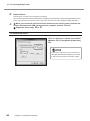
To confirm the set ID
Click the [Setup] in VPanel and confirm
[Machine ID] in the [Modeling Machine]
tab.
Select an ID and press [Set ID], and the ID is
changed. Note that the changed ID is enabled
if you restart the machine with this setting.
46
Chapter 2 Installation and Setup
2-5 Connecting Multiple Units
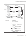
Select a machine to use
Up to four machines can be connected to a single computer but parallel use is unavailable. So select a machine to use.
Procedure
Go to [Start Menu], and click [All Programs] (or [Program]) - [Roland VPanel for DWX30] - [VPanel].
The [Printer Select] window appears
Select a machine to use.
If the machine name is not changed, "DWX-30
(Copy 1)" is displayed. (The third machine is displayed as "DWX-30 (Copy 2).")
Click [OK].
The VPanel program starts.
To change a machine to use
Quit VPanel. Then repeat the steps and to select a machine to change.
To change the name of the machine which has been set, change the name of the installed
printer (the machine you are using).
Windows 7: From [Start] menu, click [Control Panel] [Hardware and Sound] [Devices and
Printers].
Windows Vista: From [Start] menu, click [Control Panel] [Hardware and Sound] [Printers].
Windows XP: From [Start] menu, click [Control Panel] [Printers and Other Hardware] [Printers and Faxes].
Select the name of driver of the machine (Printer) you are using, and change the name.
Restart VPanel.
The name which has been changed appears on the top window.
Chapter 2 Installation and Setup
47
48
Chapter 3
Basic Operation
3-1 Starting and Quitting..............................................................50
How to Start the Machine...........................................................50
How to Shut down......................................................................52
Emergency Stop Due to Opening or Closing the Front Cover...53
3-2 Moving the Tool......................................................................54
Manual Feed...............................................................................54
Viewing the Tool Location...........................................................55
Moving to a Specific Position......................................................57
Moving to the VIEW Position......................................................57
3-3 Starting and Stopping Spindle Rotation.....................................58
Starting or Stopping the Spindle.................................................58
3-4 Pausing and Quitting Cutting.................................................59
Pausing and Resuming Operation.............................................59
Quitting Cutting...........................................................................61
3-5 Handy Panel..........................................................................62
Using the Handy Panel...............................................................62
49
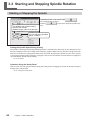
3-1 Starting and Quitting
How to Start the Machine
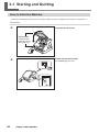
Follow the procedure below to start the machine. When startup is complete, the machine is ready for use.
Procedure
Close the front covers.
Front covers
Close first the
lower one, then
the upper one.
50
Switch on the main power.
The POWER light comes on.
Chapter 3 Basic Operation
3-1 Starting and Quitting
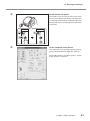
Switch on the sub power.
On the computer, start VPanel.
The spindle head, the table and the main clamp
move and the READY lamp flashes. This operation
is called initialization. When the READY light stops
flashing and remains steadily lighted, initialization
is complete.
From the [Start] menu, click [All Programs] (or [Program]) - [Roland VPanel for DWX-30] - [VPanel].
The window shown in the figure appears. Startup
of the machine is complete.
Chapter 3 Basic Operation
51
3-1 Starting and Quitting
How to Shut down
Procedure
52
On the computer, quit VPanel.
Switch off the main power.
Click [Close].
The POWER light and READY light go dark.
Chapter 3 Basic Operation
3-1 Starting and Quitting
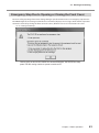
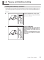
Emergency Stop Due to Opening or Closing the Front Cover
To ensure safety, opening a front cover during cutting or spindle rotation causes an emergency stop to occur.
The ERROR light on the cutting machine flashes and VPanel displays the message shown below. Operation
cannot be resumed by closing the front cover. To resume, follow the on-screen instructions to restart.
P. 50, "Starting and Quitting"
Clicking [OK] at this window makes the window disappear, but the window reappears until the cutting machine's power is switched off.
Chapter 3 Basic Operation
53
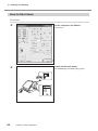
3-2 Moving the Tool
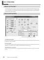
Manual Feed
Moving the tool manually is called "manual feed," and you can accomplish this using the feed buttons in
VPanel.
Feed buttons
Clicking these performs manual feed for the tool and
the rotary axis.
P. 55, "Viewing the Tool Location"
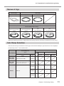
Selecting one of these enables movement
by the specified number of steps when a
feed button is clicked.
○ X, Y, and Z axes:1 step = 0.01 mm
○ A axis:1 step = 0.045° (Note that the displayed
value is truncated to the two decimal place.)
Holding down a feed button performs
movement at the selected feed rate.
Restriction on Manual Feed of the A Axis
Manual feed of the A axis is available only when the table is located at the “VIEW position.” If you want to
perform manual feed of the A axis, move the table to the “VIEW position” first.
P. 57, "Moving to the VIEW Position"
Table Movement When a Y-axis Feed Button Is Clicked
Under the default setting, Y-axis movement assumes a direction of tool movement relative to the object being cut. This means that clicking a Y-axis feed button makes the table move in a different direction from what
the arrow indicates.
Note: Manual feed cannot be performed while a cutting operation is in progress.
Operation Using the Handy Panel
You can also perform this operation using the handy panel.
P. 62, "Using the Handy Panel"
54
Chapter 3 Basic Operation
3-2 Moving the Tool
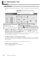
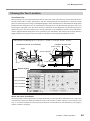
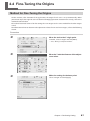
Viewing the Tool Location
Coordinate View
VPanel displays the present location of the tool as numerical values. The numerical values that indicate the
location of the tool are called "coordinates," and the starting point for the coordinates is called the "origin
point," or sometimes just the "origin." The following figure shows a location that is shifted from the origin point
by 30 millimeters along the X axis, by 10 millimeters along the Y axis, by 20 millimeters along the Z axis, and
by 15 degrees along the A axis. This X-axis distance is called the "X-axis coordinate" (or sometimes just the "X
coordinate"), the Y- and Z-axis distances are similarly called the "Y-axis coordinate" and the "Z-axis coordinate,"
and the angle of rotation along the A axis is called the "A-axis coordinate." The distances or the angle from the
origin point for the respective axes to the tool are therefore the corresponding coordinate values.
This position is expressed as "X = 30 mm, Y = 10 mm, Z = 20 mm, and A = 15 deg."
Locations of the X, Y, and Z axes
Location of the A axis
A-axis center
Origin
A-axis origin(0°)
A-axis location (15°)
VPanel display
X-axis coordinate
Y-axis coordinate
Z-axis coordinate
A-axis coordinate
About the A-axis Coordinate
The location of the A axis is indicated as an angle of rotation. In this way it differs from how the X, Y, and Z axes
are indicated. Despite this difference between angles and distances, in other respects it is treated the same
as X-, Y-, and Z-axis coordinates. The unit of measurement used to indicate A-axis coordinates is the degree,
and this cannot be changed.
Chapter 3 Basic Operation
55
3-2 Moving the Tool
Selection of the Coordinate System
On this machine, you can switch the display between the following two coordinate systems.
User Coordinate System: This is a coordinate system in which the location of the origin point can be freely
changed.
Machine Coordinate System: This is a machine-specific coordinate system in which the location of the
origin point is fixed and cannot be changed.
For the operations on this machine, it may be a good idea to leave the selection at "User coordinate system"
at all times. When you want to know the absolute location of the tool on this machine, select the machine
coordinate system.
Changing the Unit of Measurement for Display
You can switch the unit of measurement used for displaying coordinates between millimeters and inches.
Click the [Preference], then select the unit.
56
Chapter 3 Basic Operation
3-2 Moving the Tool
Moving to a Specific Position
Selecting a destination from the list and clicking the
[Move] button makes the tool move rapidly to the
selected location. Clicking the [Stop] button stops
movement.
Note: Movement to "Rotation Center Y" is possible only when
detection of the jig location has been performed and the center
of the axis of rotation has been established.
When "User Specify" Is Selected
Clicking the [Move] button makes the window shown at left appear. You can specify the location of the movement destination
by entering the values you want for "Coordinates" or "Amount
of relative movement."
Moving to the VIEW Position
Press the VIEW button on the built-in panel.
The tool moves to the highest position, after which the table
moves to the front of the machine. This location is called
the "VIEW position." You use this when performing such operations as attaching or detaching a tool, installing a jig, or
mounting a workpiece. The READY light flashes while movement is in progress. When the READY light stops flashing and
remains steadily lighted, movement is complete.
This operation cannot be performed while a front cover is
open. Close the front cover, then perform the operation.
Chapter 3 Basic Operation
57
3-3 Starting and Stopping Spindle Rotation
Starting or Stopping the Spindle
Close the front covers and click
This displays the present rotating
speed of the spindle.
Settable range: 6,000 to 30,000 rpm
.
The spindle begins to rotate.
Clicking
a second time stops the spindle rotation.
You can adjust the spindle's
speed of rotation.
Setting the Spindle Speed During Cutting
The spindle's rotating speed during cutting operations is controlled by commands in the cutting data sent
from the computer, and so the setting made in VPanel is ignored. Note, however, that the setting made with
VPanel is used when the cutting data contains no command specifying the spindle speed, or if the setting
is made again in VPanel while cutting is in progress. You can also use VPanel's override feature to adjust the
speed of spindle rotation during cutting.
P. 80, "Override"
Operation Using the Handy Panel
You can start and stop spindle rotation using the handy panel. Changing the speed of rotation using the
handy panel is not possible.
P. 62, "Using the Handy Panel"
58
Chapter 3 Basic Operation
3-4 Pausing and Quitting Cutting
Pausing and Resuming Operation
This operation pauses cutting. You perform it using the built-in panel. This also makes it possible to resume cutting at the paused position after an operation such as moving the tool to check the status of the workpiece.
Procedure
Press the PAUSE button during cutting.
Press the VIEW button.
Tool movement pauses. The PAUSE light comes on
and the READY light flashes. Rotation of the spindle
does not stop at this time.
Rotation of the spindle stops, the table moves to
the front of the machine (the VIEW position). The
READY light flashes while the tool and table are
moving.
This operation cannot be performed while a front
cover is open. Close the front cover, then perform
the operation.
Chapter 3 Basic Operation
59
3-4 Pausing and Quitting Cutting
Hold down the PAUSE button for one second or longer.
The tool returns to the position where operation
was paused, and cutting resumes. After the tool
starts moving, the READY light flashes until cutting resumes. After cutting resumes, the PAUSE
light goes dark.
This operation cannot be performed while a front
cover is open. Close the front cover, then perform
the operation.
Important !
Before opening the front cover while operation is paused, first make sure that rotation of the spindle is stopped.
For safety, opening the front cover while the spindle is turning makes the machine perform an emergency stop.
Be sure to note that if this happens, it’s necessary to quit the operation and start over from the beginning.
P. 53, “Emergency Stop Due to Opening or Closing the Front Cover”
Other Operations Possible While Paused
VPanel
Tool movement using manual feed
P. 54, "Manual Feed"
Starting or stopping spindle rotation
P. 58, "Starting and Stopping Spindle Rotation"
Changing the spindle speed
P. 80, "Override"
Adjusting the tool feed rate
P. 80, "Override"
Handy Panel
Starting or stopping spindle rotation
P. 62, "Using the Handy Panel"
Moving the tool
P. 62, "Using the Handy Panel"
60
Chapter 3 Basic Operation
3-4 Pausing and Quitting Cutting
Quitting Cutting
This stops cutting through operation using the built-in panel. Unlike pausing operation, cutting cannot be
resumed.
Procedure
Press the PAUSE button during cutting.
Hold down the CANCEL button for two
seconds or longer.
Movement of the tool pauses. The PAUSE light
comes on and the READY light flashes. Rotation of
the spindle does not stop at this time.
When the PAUSE light goes dark and the READY
light is lighted, cutting has completed stopping.
Rotation of the spindle stops at this time.
Chapter 3 Basic Operation
61
3-5 Handy Panel
Using the Handy Panel
This is an operation panel connected to the cutting machine by a cable. You can use it to perform such operations as moving the tool or switching spindle rotation on and off. This makes it a handy tool when you want to
perform operations while monitoring the material or the tool position from a location close to the machine.
X-, Y-, and Z-axis movement buttons
These are the respective movement buttons for the X, Y, and Z axes. Pressing just these buttons performs slow movement.
Y-axis movement assumes a direction of tool movement relative to the
object being cut. This means that pressing
or
makes the table
move in the direction opposite to what the arrow indicates ( : movement toward the back of the machine,
: movement toward the front
of the machine).
A-axis button
Pressing this button makes the movement axis change to the A axis.
Pressing this button does not actually rotate the A axis. To rotate the A
axis, you press this button, then turn the dial.
Note that manual feed of the A axis is available only when the table is
located at the “VIEW position.”
Feed button
Pressing a movement button or turning the dial while holding down this button performs rapid movement.
Spindle button
Holding this down for one second or longer while the spindle is stopped sounds an audible beep and
starts spindle rotation. Pressing this during spindle rotation sounds a beep and stops rotation.
62
Chapter 3 Basic Operation
3-5 Handy Panel
LEDs
This indicates the axis of movement using the handy panel. Pressing the movement button for an axis
makes the corresponding LED light up.
Dial
Turning this moves the selected axis (the axis whose LED is illuminated).
Operating the Handy Panel and VPanel at the Same Time
Never operate the handy panel and VPanel simultaneously. Operation using VPanel becomes impossible while
the handy panel is being used.
Chapter 3 Basic Operation
63
64
Chapter 4
Performing Cutting
4-1 Before Starting Operations....................................................66
Spindle Run-in (Warm-up)..........................................................66
Detection of the Jig Location......................................................67
4-2 Preparation for and Performing Cutting................................... 70
Usable Workpieces.....................................................................70
Names of Jigs.............................................................................71
Sub Clamp Selection..................................................................71
Cuttable Area..............................................................................72
Misalignment of centers of workpiece height and A axis (Offset)...
73
Mounting the Workpiece . ..........................................................74
Installing a Tool...........................................................................76
Tool Length Measurement..........................................................77
Starting Cutting...........................................................................79
4-3 Override.................................................................................80
What's an Override?...................................................................80
How to Set Overrides.................................................................80
4-4 Fine-Tuning the Origins.........................................................81
Method for Fine-Tuning the Origins............................................81
Determining the Adjustment Value.............................................82
65
4-1 Before Starting Operations
Spindle Run-in (Warm-up)
In any of the following cases, perform run-in (warm-up) operation for the spindle. Failure to do so may result
in unstable spindle rotation.
When using for the first time after purchase
After moving the machine and reinstalling it at a different location
After replacing the spindle unit
When using in a low-temperature environment
Spindle Run-in takes maximum one hour.
Procedure
Close the front covers.
Go to [Start Menu], and click [All Programs] (or [Program]) - [Roland VPanel for DWX30] - [VPanel].
The VPanel program starts.
Click [Setup].
The [Setup] window appears.
Click [Modeling Machine] tab.
Click [Run-in].
The run-in operation starts.
66
Chapter 4 Performing Cutting
4-1 Before Starting Operations
Detection of the Jig Location
WARNING
Never inadvertently touch the computer or handy panel while performing
this task.
Unintended operation of the machine may result in injury.
WARNING
Securely fasten the jig in place. After securing in place, make sure no
wrenches or other articles have inadvertently been left behind.
Otherwise such articles may be thrown from the machine with force, posing
a risk of injury.
Carry out “Detection of the jib location” in order to determine the reference position for cutting.
Important !
Detecting the location of the jig is a necessary procedure for determining the reference position for cutting. Be sure to carry this out when you use the machine for the first time after purchase or whenever you
change the jig.
Make sure the clamp, detection pin, tool sensor, and attachment for detection are clean and free of dust,
chips, and the like. Any buildup on these may prevent correct response by the sensor and make correct
detection of the jig location impossible. In some cases, such buildup may cause breakage of the detection
pin, resulting in injury or damage.
Procedure
Close the front covers and press the VIEW button.
P. 57, "Moving to the VIEW Position"
v
w
Open the front covers and remove the dust
collection capsule.
Install the detection pin.
P. 76, "Installing a Tool"
Chapter 4 Performing Cutting
67
4-1 Before Starting Operations
x
Install the attachment for detection on the detection pin.
Attachment
for detection
Collet
Push it.
y
Make some
space.
Close the front covers, then in VPanel,
click [Jig].
The [Jig Detection] window appears.
z
Click [Start Sensing].
Make sure no buildup of cutting waste
is present on the tool sensor, then click
[Continue].
Detection of the location of the jig starts.
68
Chapter 4 Performing Cutting
4-1 Before Starting Operations
{
When the window shown in the figure appears, click [OK].
Click [Close].
An illustration of the clamp is displayed in “Calibration” of VPanel.
|
Remove the attachment for detection.
Detection of the jig location is finished.
Chapter 4 Performing Cutting
69
4-2 Preparation for and Performing Cutting
Usable Workpieces
Type of Workpieces
Modeling wax, Zirconia (pre-sintered)
Type (shape) and size of workpiece
Size (mm)
Type (Shape) of Workpeice
External diameter, or
width × depth
Height
Disc without levels
diameter 98 to 100
10 to 14
Disc with levels
Level section:
diameter 98 to 100
Body section:
diameter 95
Level section: 10
Body section: 12 to 26
Level section
Body section
12 to 16
Block
40x75
18 to 22
24 to 26
70
Chapter 4 Performing Cutting
4-2 Preparation for and Performing Cutting
Names of Jigs
Main Clamp
Sub Clamp
Main Clamp*
Cap*
Spacer
Sub Clamp
Clamp for Block Workpiece (The height of a workpiece to be used is displayed
on the surface of the clamp.)
C-1
C-2
D-1
D-2
For 12 to 16/ 18 to
For 12 to 16/ 18 to
For 24 to 26mm
For 24 to 26mm
22mm
22mm
*NOTE: The modeling machine is shipped from the factory with the sub clamp installed on the main clamp.
Sub Clamp Selection
Select the sub clamp in accordance with the type and size of the workpiece you want to use. Use an appropriate sub clamp with “” in the table below.
Type of Workpiece (shape)
Sub-clamp
Size of Workpiece
(mm)
Spacer
Cap
External diameter/ width ×
depth
Height
Disc without levels
diameter 98 to 100
10 to 14
Disc with
levels
Level section: diameter 98 to 100
Body section: diameter 95
12 to 26
12 to 16
18 to 22
24 to 26
Block
40 x 75
Clamp for block
C-1,C-2
D-1,D-2
Chapter 4 Performing Cutting
71
4-2 Preparation for and Performing Cutting
Cuttable Area
The size of the workpiece that can be mounted in the jig and the actual cuttable area are different. Refer to the
figure below to determine the size of the workpiece to use and the size of the model you're producing.
In the case of a Disc workpiece
In the case of a Block workpiece
72
Chapter 4 Performing Cutting
4-2 Preparation for and Performing Cutting
Misalignment of centers of workpiece height and A axis (Offset)
Create a cutting data with caution, when you’re using a disc workpiece without levels or a block workpiece,
since the centers of the workpiece set on the clamp and A axis are misaligned.
*NOTE: When you’re using a disc workpiece with levels, the centers of the workpiece set on the clamp and A
axis are aligned at all times.
A axis
centers of the
workpiece
Work
Clamp
The following table indicates the misalignment of centers of workpiece height and A axis in each workpiece
size. The values of α and β in the table correspond to “α” and “β” on the above figure. Create a cutting data
referring to this table.
Workpiece Type
(shape)
Disc without levels
Block
Workpiece Size
(mm)
External diameter/
Height
width × depth
diameter 98 to 100
40 x 75
α
β
10
5
5
12
7
5
14
9
5
12
3
9
14
5
9
16
7
9
18
9
9
20
11
9
22
13
9
24
11
13
26
13
13
Chapter 4 Performing Cutting
73
4-2 Preparation for and Performing Cutting
Mounting the Workpiece
Procedure
w
Close the front covers and press the VIEW button.
P. 57, Moving to the VIEW Position
Remove the cover of the dust collection capsule if it is attached.
Mount the workpiece on the main-clamp.
The sub clamp (s) varies according to the type of the workpiece. Mount according to the order shown in
the figure and tighten the cap at the end.
In the case of a Disc workpiece
Without levels
With levels
Cap
workpiece
Main-clamp
74
Chapter 4 Performing Cutting
4-2 Preparation for and Performing Cutting
In the case of a Block workpiece
Height: 18 to 22
Height: 12 to 16
Cap
Sub-clamp
Spacer
Sub-clamp
Clamp C-1 for
block workpiece
workpiece
Clamp C-2 for
block workpiece
Main-clamp
Unit: mm
Height: 24 to 26
Cap
Sub-clamp
Clamp D-1 for block
workpiece
workpiece
Clamp D-2 for
block workpiece
Main-clamp
Unit: mm
Chapter 4 Performing Cutting
75
4-2 Preparation for and Performing Cutting
Installing a Tool
This describes how to install a tool for cutting. You can use the same method to install a detection pin.
*NOTE: The tools are optional items.
Important Notes When Selecting a Tool
Select a tool giving careful attention to such matters as the length of the tool and the shape of its tip.
WARNING
Never inadvertently touch the computer or handy panel while performing
this task.
Unintended operation of the machine may result in injury.
WARNING
Securely fasten the cutting tool and workpiece in place. After securing in
place, make sure no wrenches or other articles have inadvertently been
left behind.
Otherwise such articles may be thrown from the machine with force, posing
a risk of injury.
CAUTION
Caution: cutting tool.
The cutting tool is sharp. To avoid injury, exercise caution.
Procedure
Close the front covers and press the VIEW button.
P. 57, "Moving to the VIEW Position"
When movement to the VIEW position is complete, open the front covers.
Loosely tighten the collet.
Spindle unit
Collet
Spanner (17mm)
76
Chapter 4 Performing Cutting
Secure the spindle unit in place using the 17-mm
spanner, then screw in the collet until it is fingertight.
To mount the detection pin, use the collet of diameter 4 mm.
4-2 Preparation for and Performing Cutting
Insert the tool (optionally available) into
the collet until it makes flush contact.
It is recommended to adjust the amount of extension of the tool tip to around 30mm. Also, use a
collet and tool of matching diameters.
About
30 mm
Tool
For a detection pin
Be sure to use with the tool flush against the magnetic area of the collet. Otherwise, detection of the
jig location may fail.
Detection pin
Fully tighten the collet.
Using two spanners, tighten the collet fully. The
appropriate tightening torque is 3.2 N-m (32 kgfcm).
Spanner (17mm)
Spanner
(10 mm)
After mounting a tool, also perform [Tool Length Measurement] described on the next page.
Tool Length Measurement
This measures the length of the mounted tool. Make sure to perform this after changing the tool.
Before Tool Length Measurement
Make sure that detection of the jig location has finished. If detection of the jig location has not finished, the
tool length measurement may not be possible.
P. 67, "Detection of the Jig Location"
Procedure
Mount a cutting tool and close the front covers.
P. 76, "Installing a Tool"
Chapter 4 Performing Cutting
77
4-2 Preparation for and Performing Cutting
Click [Tool].
Make sure no buildup of cutting waste
is present on the tool sensor, then click
[Continue].
The tool moves and descends to the position where
it touches the tool sensor.
Click [OK].
The tool length measurement finishes.
After the tool length measurement finishes, the red
arrow is displayed in the center of the main clamp.
78
Chapter 4 Performing Cutting
4-2 Preparation for and Performing Cutting
Starting Cutting
Send cutting data from the computer and start cutting. The feed rate and the speed of spindle rotation are
determined by the cutting data received.
Before Starting Cutting
Make sure that the following procedures have finished. If these procedures have not finished, the intended
cutting may not be possible.
Detection of the jig location
P. 67, "Detection of the jig location"
Tool Length Measurement
P.77, "Tool Length Measurement"
Procedure
v
w
x
y
Verify that the cover of the dust collection capsule is properly attached.
Close the front covers.
Send cutting data from the computer and start cutting.
When the tool type has been changed during cutting, measure the tool length again and resume cutting.
P.77, "Tool Length Measurement"
When cutting has finished, press the VIEW button.
P. 57, "Moving to the VIEW Position"
Open the front covers and remove the workpiece.
This completes the cutting. After removing the workpiece, trim away any excess areas.
Chapter 4 Performing Cutting
79
4-3 Override
What's an Override?
On this machine, you can adjust the cutting speed and the speed of spindle rotation while cutting is in progress. You adjust these by specifying the ratio of change relative to the present speed, as a percentage. This
feature is called "override." This feature is useful when you want to change the respective speeds on the fly as
you monitor the status of cutting.
How to Set Overrides
Clicking these buttons adjusts the values.
Cutting-speed Override
This is the speed of tool movement when cutting the workpiece. The speed specified by the command in the
cutting data is taken to be 100%.
Spindle Override
This is the speed of spindle rotation. The speed specified by the command in the cutting data is taken to be
100%. This is also effective when rotating the spindle during manual operations.
Important Notes on Overrides
Setting an override does not let you perform operation beyond the machine's maximum or minimum
speeds.
80
Chapter 4 Performing Cutting
4-4 Fine-Tuning the Origins
Method for Fine-Tuning the Origins
On this machine, after detection of the jig location, the origin of each axis is set up automatically. When
you want to adjust the origin of each axis obtained through jig-location detection more exactly, refer to the
method described below.
The method described below is for fine-tuning the Y-axis origin. Use the same method for the other origins
as well.
For information on how to determine the adjustment values of Y-axis and Z-axis origins, refer to the following
section.
Procedure
Move the tool to the Y origin point.
In VPanel, select "Y origin" and click [Move].
P. 57, "Moving to a Specific Position"
v
Move the Y axis the distance of the adjustment value.
w
Make the setting for the base point.
Select "Y-origin" and click [Apply].
Chapter 4 Performing Cutting
81
4-4 Fine-Tuning the Origins
Determining the Adjustment Value
Adjustment Value for the Y-axis Origin
You determine the adjustment value from the difference in levels at the seam produced between the first and
second surfaces in two-surface cutting. The estimated adjustment value is one-half the difference in levels.
However, be careful to note the sign of the value (plus or minus). As the figure shows, the sign of the adjustment value (positive or negative) changes depending on the direction of the misalignment.
As an example, when the difference in levels is 0.2 millimeters, with the upper level misaligned in the positive
direction and the lower level misaligned in the negative direction along the Y axis, then the estimated adjustment value is -0.1 millimeters.
Difference in levels
Difference in levels
Negative adjustment value
Positive adjustment value
Adjustment Value for the Z-axis Origin
You determine the adjustment value from the discrepancy between the expected and actual values for the
thickness of the finished result of two-surface cutting. The estimated adjustment value is one-half the discrepancy. However, be careful to note the sign of the value (plus or minus). When the actual value is larger than
the expected value, the adjustment value is negative.
As an example, if data for a height of 50 millimeters yields cutting results that are 50.1 millimeters, the estimated
adjustment value is -0.05 millimeters.
Height specified by the data
Actual height
Positive adjustment value
Height specified by the data
Actual height
Negative adjustment value
82
Chapter 4 Performing Cutting
Chapter 5
Appendix
5-1 Maintenance..........................................................................84
Care and Maintenance of the Cutting Machine..........................84
Care for the Detection Pin and the Attachment for Detection.....85
Maintenance of the Spindle Unit................................................86
5-2 What to Do If..........................................................................87
Initialization is not performed or initialization fails......................87
VPanel doesn't start correctly.....................................................87
Operations are ignored...............................................................87
The spindle doesn't rotate..........................................................88
Abnormal cutting is performed....................................................88
Jig detection failed......................................................................88
The feed rate or spindle speed is wrong....................................88
The cutting results are not attractive..........................................88
Installation is impossible.............................................................88
Uninstalling the Driver................................................................89
The computer shut down............................................................90
5-3 Responding to an Error Message..........................................91
5-4 Power Rating and Serial Number Locations..........................93
5-5 Expansion Connector Specification.......................................94
Expansion Connector A..............................................................94
Expansion Connector B..............................................................97
5-6 Dimensional Drawings...........................................................98
Dimension of Outline..................................................................98
Opening Size to Connect a Dust Collector.................................98
Rotary Axis/Tool Sensor Dimension...........................................99
X-, Y- and Z-axis Travel / Table Dimension...............................100
5-7 Specifications.......................................................................101
Main Specifications...................................................................101
System Requirements for USB Connection.............................102
83
5-1 Maintenance
Care and Maintenance of the Cutting Machine
WARNING
Never use a pneumatic blower.
This machine is not compatible with a pneumatic blower. Cutting waste may
get inside the machine and cause fire or electrical shock.
WARNING
Never use a solvent such as gasoline, alcohol, or thinner to perform
cleaning.
Doing so may cause fire.
WARNING
Disconnect the power cord before performing cleaning or maintenance.
Attempting such operations while the machine is connected to a power source
may result in injury or electrical shock.
WARNING
When using a vacuum cleaner to take up cutting waste, exercise caution
to prevent fire or dust explosion.
Taking up fine cuttings using an ordinary vacuum cleaner may cause danger
of fire or explosion. Check with the manufacturer of the vacuum cleaner. When
the safety of use cannot be determined, clean using a brush or the like, without
using the vacuum cleaner.
CAUTION
Caution: high temperatures.
The cutting tool and spindle motor become hot. Exercise caution to avoid fire
or burns.
CAUTION
When performing maintenance, be sure to keep the tool detached.
Contact with the blade may cause injury.
This machine is a precision device. Carry out daily care and maintenance.
Carefully clean away cutting waste. Operating the machine with a large amount of cutting waste present
may cause malfunction.
Never apply silicone substances (oil, grease, spray, etc.) to the machine. Doing so may cause poor switch
contact.
Never apply lubrication.
Cleaning around the table
After operation, use a brush or the like to clean away any buildup of cutting waste around the table or on the
machine.
84
Chapter 5 Appendix
5-1 Maintenance
Cleaning the dust tray
After operation, dispose of any cutting waste that has collected in the dust tray.
Dust tray
Cleaning inside of the dust collection capsule
When cutting is finished, fix the cleaning nozzle to the dust collection hose C and remove the cover of the
dust collection capsule to clean the machine.
By turning the top, you can make it applicable to sweeping or vacuuming.
Dust collection hose C
Cleaning nozzle
Cap
Care for the Detection Pin and the Attachment for Detection
Take care of the detection pin and the attachment for detection on a routine basis. The detection pin or the
attachment that gathers rust or dust will prevent the accurate detection, which may result in the situation
where you cannot perform cutting as intended or where the machine should be damaged.
Care, Maintenance, and Storage Methods
After use, wipe clean using a clean cloth, apply rust-preventive oil generously, and store.
When the item will be out of use for a prolonged period, store in a location with low humidity and little
fluctuation in temperature.
Chapter 5 Appendix
85
5-1 Maintenance
Maintenance of the Spindle Unit
The spindle unit and the belt are parts that wear out. The replacement cycle varies according to usage conditions, but as a general guide, you should replace them after every 2,000 hours of use. You can use VPanel to
view the total working time of the spindle. Refer to this to determine when replacement is needed.
For information on how to replace the spindle unit, refer to the documentation included with the ZS-30
replacement spindle unit.
Checking the total working time of the spindle using VPanel
Click "Setup".
The total working time
of the spindle is reset.
Total working time
of the spindle
86
Chapter 5 Appendix
5-2 What to Do If...
Initialization is not performed or initialization fails.
Is a front cover open?
When starting the machine, close the upper and lower
front covers. For safety, initialization is not performed
when a cover remains open at startup.
Is anything caught on the spindle head or
table?
Check whether something has become caught and is
impeding initialization.
Is anything caught on the main clamp?
Perform the followings and remove any obstructions that
impede initialization.
1. Switch off the main power, and then switch on the
main power.
Never switch on the sub power.
2. Hold down
of the handy panel.
The LED lamp A lights up. Turning the handle, the main
clamp (A-axis) turns.
VPanel doesn't start correctly.
Has initialization been completed?
Before you start VPanel, first switch on the power to the
machine.
P. 50, "Starting and quitting"
Is the computer connected?
Check whether the connector cable has come loose.
Is the driver installed correctly?
If the connection to the computer is not made in the
sequence described, the driver may fail to be installed
correctly. VPanel does not function normally when driver
is misconfigured. Check again to ensure that the connection was made using the correct procedure.
P. 41, "Installing the Windows-based Driver"
Operations are ignored.
Is the cable connected?
Connect the cable securely.
P. 39, "Cable Connections"
Was the machine started according to the correct procedure?
Simply switching on the power does not enable operation. Start the machine using the correct procedure.
Are front covers open?
This machine restricts some operations when a front
cover is open. Close both the upper and lower front
covers.
Is the ERROR light flashing?
The ERROR light is flashing rapidly.
An emergency stop occurred because a serious error was
detected. Resuming operation is not possible. A description of the error is displayed in VPanel. Switch off the main
power to quit the operation, eliminate the cause, then
redo the operation from the beginning. If the emergency
stops continue even after eliminating the cause, contact
your authorized Roland DG Corp. dealer.
P. 50, "Starting and quitting," p. 91, "Responding to an Error
Message"
The ERROR light is flashing slowly.
Operation was paused because an error was detected. A
description of the error is displayed in VPanel. Follow the
displayed instructions to resume operation.
P. 59, "Pausing and Resuming Operation"
Is operation paused?
When the PAUSE light is on, it means that operation
is paused. When the machine is paused, cutting stops
and some operations are restricted. Cancel the paused
state.
P. 59, "Pausing and Resuming Operation"
Is a large amount of cutting waste present?
Clean away any cutting waste. Clean the area around the
spindle especially carefully.
P. 84, "Care and Maintenance of the Cutting Machine"
Is the handy panel connected correctly?
When inserting, orient correctly and insert fully. Also,
before inserting or removing the connector cable for
the handy panel, switch off the power to the machine.
Making the connection while the power is on may cause
the machine to malfunction.
P. 39, "Connecting the Handy Panel," p. 50, "Starting and
Quitting"
Is the driver installed correctly?
If the connection to the computer is not made in the
sequence described, the driver may fail to be installed
correctly. Check again to ensure that the connection was
P. 50, "Starting and quitting"
Chapter 5 Appendix
87
5-2 What to Do if...
made using the correct procedure.
P. 41, "Installing the Windows-based Driver"
Is VPanel displaying an error message?
P. 91, "Responding to an Error Message"
Is the connection method correct when connecting multiple units?
The connection method may be incorrect when connecting more than one machine. Confirm the correct
method.
P. 41,"Connecting Multiple Units"
The spindle doesn't rotate.
Are front covers open?
For safety, the spindle does not rotate when are front
covers are open. Close both the upper and lower front
covers.
Is a large amount of cutting waste present?
Clean away any cutting waste. Clean the area around the
spindle especially carefully.
P. 84, "Care and Maintenance of the Cutting Machine"
Jig detection failed.
Is the jig, detection pin, sensor or detection
attachment dirt?
Clean away any grime on the jig, detection pin, sensor, or
detection attachment. Soiling due to buildup of cutting
waste or the like on any of these may impede correct
sensor operation, making correct detection of the jig
impossible.
The feed rate or spindle speed is wrong.
Has an override been set?
An override changes the feed rate or spindle speed.
Check the settings for overrides. Unless you have a
special reason for changing them, leave all overrides
set at 100%.
P. 80, "Override"
The cutting results are not attractive.
Is the workpiece securely mounted in place?
Redo loading of the workpiece. Fasten in place securely,
so that the workpiece will not slip out of place or come
loose because of tool pressure or vibration during cutting.
Has a setting been made to keep the spindle
from rotating?
In VPanel, click the [Setup], then click the [Modeling
Machine] tab. Here, select the [Control spindle via commands] check box.
Abnormal cutting is performed.
Have the origin been set at correct location?
If jig-location detection, or detection of the reference
position for cutting is not carried out correctly, the origin
point may not be set at the correct location. If the origin
point is not set at the correct location, cutting at an unintended location or at the wrong depth may occur.
Is the misalignment of centers of workpiece
height and A axis updated to the cutting
data?
The centers of workpiece height and A axis are not
aligned, when you’re using a cylindrical workpiece without levels or a block workpiece. Create a cutting data with
caution on this point.
P. 73, "Misalignment of centers of workpiece height
and A axis (Offset)"
88
Chapter 5 Appendix
Is the tool firmly secured in place?
Retighten the collet to secure in place firmly.
P. 76, "Installing a Tool"
Is the tool tip worn?
If the tip of the tool is worn, replace with a new tool.
Installation is impossible
If installation quits partway through, or if the wizard does
not appear when you make the connection with a USB
cable, take action as follows.
Windows 7
1. If the [Found New Hardware] appears, click [Cancel]
to close it.
2. Click the [Start] menu, then right-click [Computer].
Click [Properties].
3. Click [Device Manager]. The [User Account Control] appears, click [Continue]. The [Device Manager] appears.
4. At the [View] menu, click [Show hidden devices].
5. In the list, find [Other devices], then double-click
it. When the model name you are using or [Unknown
device] appears below the item you selected, click it to
choose it.
5-2 What to Do if...
6. Go to the [Action] menu, and click [Uninstall].
7. In "Confirm Device Uninstall" window, select [Delete
the driver software for this device.], and then click [OK].
8. Detach the USB cable connected to the printer, and
the restart Windows.
9. Uninstall the driver. Carry out the steps from step 3
in page 89 “Uninstall the Driver Windows 7” to uninstall
the driver.
10. Install the driver again according to the procedure in
page 41 “Installing and Setting Up the Software.”
10. Uninstall the driver. Carry out the steps from step 3
in page 90 “Uninstall the Driver Windows XP” to uninstall
the driver.
11. Install the driver again according to the procedure in
page 41 “Installing and Setting Up the Software.”
Windows Vista
Windows 7
1. If the [Found New Hardware] appears, click [Cancel]
to close it.
2. Click the [Start] menu, then right-click [Computer].
Click [Properties].
3. Click [Device Manager]. The [User Account Control] appears, click [Continue]. The [Device Manager] appears.
4. At the [View] menu, click [Show hidden devices].
5. In the list, find [Printers] or [Other device], then doubleclick it. When the model name you are using or [Unknown
device] appears below the item you selected, click it to
choose it.
6. Go to the [Action] menu, and click [Uninstall].
7. In "Confirm Device Uninstall" window, select [Delete
the driver software for this device.], then click [OK].
8. Detach the USB cable connected to the printer, and
the restart Windows.
9. Uninstall the driver. Carry out the steps from step 3 in
page 89“Uninstall the Driver Windows Vista” to uninstall
the driver.
10. Install the driver again according to the procedure in
page 41 “Installing and Setting Up the Software.”
Windows XP
1. If the [Found New Hardware Wizard] appears, click
[Finish] to close it.
2. Click the [Start] menu, then right-click [My Computer].
Click [Properties].
3. Click the [Hardware] tab, then click [Device Manager].
The [Device Manager] appears.
4. At the [View] menu, click [Show hidden devices].
5. In the list, find [Printers] or [Other device], then doubleclick it. When the model name you are using or [Unknown
device] appears below the item you selected, click it to
choose it.
6. Go to the [Action] menu, and click [Uninstall].
7. In "Confirm Device Uninstall" window, crick [OK].
8. Close the [Device Manager] and click [OK].
9. Detach the USB cable connected to the printer, and
the restart Windows.
Uninstalling the Driver
When uninstalling the driver, perform following operation.
*If the driver is uninstalled without following the procedure given below, there is a possibility that it might not
be able to be re-installed.
1. Before you start uninstallation of the driver, unplug
the USB cables from your computer.
2. Log on to Windows as “Administrator” right.
3. From the [Start] menu, click [Control Panel]. Click
[Uninstall a program].
4. Click the driver for the machine to delete to select it,
then Click [Uninstall].
5. A message prompting you to confirm deletion appears. Click [Yes].
6. From the [Start] menu, choose [All Programs], then
[Accessories], then [Run], and then click [Browse].
7. Choose the name of the drive or folder where the
driver is located. (*)
8. Select "SETUP.EXE" and click [Open], then click [OK].
9. The [User Account Control] appears, click [Allow].
10. The Setup program for the driver starts.
11. Click [Uninstall] to choose it. Select the machine to
delete, then click [Start].
12. If it is necessary to restart your computer, a window
prompting you to restart it appears. Click [Yes].
13.The uninstallation finishes after the computer restarts.
(*) When using the CD-ROM, specify the folder as shown
below (assuming your CD-ROM drive is the D drive).
D:\Drivers\25D\WIN7X64 (64 bit edition)
D:\Drivers\25D\WIN7X86 (32 bit edition)
If you're not using the CD-ROM, go to the Roland DG
Corp. website (http://www.rolanddg.com/) and download the driver for the machine you want to delete,
then specify the folder where you want to expand the
downloaded file.
Windows Vista
1. Before you start uninstallation of the driver, unplug
the USB cables from your computer.
2. Log on to Windows as “Administrators” right.
Chapter 5 Appendix
89
5-2 What to Do if...
3. From the [Start] menu, click [Control Panel]. From the
[Hardware and Sound] group, click [Printer]. [Printer]
folder opens.
4. Click the model name’s icon you are using. From the
[Organize] menu, click [Delete]. The [User Account Control] appears, click [Continue].
5. A message prompting you to confirm deletion appears. Click [Yes].
6. In the [Printers] folder, right-click any location where
no printer icon is present. From the [Run as administrator] menu, select [Server Properties]. The [User Account
Control] appears, click [Continue].
7. Click the [Drivers] tab, then from the [Installed printer
drivers] list, choose the machine to delete. Click [Remove].
8. The [Remove Driver And Package] appears, select
[Remove driver and driver package]. Click [OK].
9. When the prompt message appears, click [Yes].
10. The package and driver to delete are displayed. Make
sure that what is displayed is the machine you want to
delete, then click [Delete].
11. The items that have been deleted are displayed.
Click [OK].
12. Click [Close] on [Remove Driver And Package] window.
13. From the [Start] menu, choose [All Programs], then
[Accessories], then [Run], and then click [Browse].
14. Choose the name of the drive or folder where the
driver is located. (*)
15. Select "SETUP.EXE" and click [Open], then click [OK].
16. The [User Account Control] appears, click [Allow].
17. The Setup program for the driver starts.
18. Click [Uninstall] to choose it. Select the machine to
delete, then click [Start].
19. If it is necessary to restart your computer, a window
prompting you to restart it appears. Click [Yes].
20. The uninstallation finishes after the computer restarts.
(*) When using the CD-ROM, specify the folder as shown
below (assuming your CD-ROM drive is the D drive).
D:\Drivers\25D\WINVISTAX64 (64 bit edition)
D:\Drivers\25D\WINVISTAX86 (32 bit edition)
If you're not using the CD-ROM, go to the Roland DG
Corp. website (http://www.rolanddg.com/) and download the driver for the machine you want to delete,
then specify the folder where you want to expand the
downloaded file.
Windows XP
1. Before you start uninstallation of the driver, unplug
the USB cables from your computer.
2. Log on to Windows as “Administrators” right.
3. From the [Start] menu, click [Control Panel]. Click
[Printers and Other Hardware], then click [Printers and
Faxes].
4. Click the model name’s icon you are using. From the
[File] menu, choose [Delete].
5. A message prompting you to confirm deletion appears. Click [Yes].
6. Go to [File] and select [Server Properties].
7. Click the [Driver] tab, then from the [Installed printer
drivers] list, choose the machine to delete.
8. Click [Delete]. When the prompt message appears,
click [Yes].
9. From the [Start] menu, select [Run], then click
[Browse].
10. From the [File Locations] list, choose the name of the
drive or folder where the driver is located. (*)
11. Select "SETUP.EXE" and click [Open], then click [OK].
12. The Setup program for the driver starts.
13. Click [Uninstall] to choose it. Select the machine to
delete, then click [Start].
14. If it is necessary to restart your computer, a window
prompting you to restart it appears. Click [Yes].
15. The uninstallation finishes after the computer restarts.
(*) When using the CD-ROM, specify the folder as shown
below (assuming your CD-ROM drive is the D drive).
D:\Drivers\25D\WINXPX64 (64 bit edition)
D:\Drivers\25D\WINXPX86 (32 bit edition)
If you're not using the CD-ROM, go to the Roland DG
Corp. website (http://www.rolanddg.com/) and download the driver for the machine you want to delete,
then specify the folder where you want to expand the
downloaded file.
The computer shut down
Is a machine with a same ID connected to the
computer?
When more than one machine is connected to the
computer, if machines with a same ID are connected at
the same time, the computer might shut down. If the
computer shuts down, turn off the power of all the connected machines and disconnect the USB cables from
the computer. Next, restart the computer, and then start
VPanel. If VPanel does not start, install it again. Then,
make the setting again in a way that a same ID is not
assigned to more than one machine.
P. 42, "Installing and Setting Up VPanel," p. 44, "Connecting
Multiple Units"
90
Chapter 5 Appendix
5-3 Responding to an Error Message
This section describes the error messages that
may appear on the monitor of the computer
you're using, and how to take action to remedy
the problem. If the action described here does
not correct the problem, or if an error message
not described here appears, contact your authorized Roland DG Corp. dealer.
No response is returned from machine.
Click [OK]. The machine may have accidentally been
switched off, or the connector cable may have come
loose. After checking, restart the machine.
P. 50, "Starting and Quitting"
No modeling machine was found.
Click [Quit], then restart the machine and redo the operation from the beginning.
P. 50, "Starting and Quitting"
Detection pin absent or not installed correctly.
During jig detection, either the detection pin was not
installed or the amount of extension was incorrect, and
so detection was aborted. Clicking "OK" cancels detection operation. Make sure the detection pin is installed
correctly, then redo detection of the jig location.
P. 76, "Installing a Tool"
Operation is impossible because jig detection
has not been performed.
This appears if "Move to Rotation center Y" is selected in
VPanel when jig detection has never been performed.
Performing jig detection makes it possible to execute
movement to center of rotation Y.
P. 57, "Moving to a Specific Position
Detection of the jig failed.
The sensor failed to respond during jig detection, and
so detection failed. The sensor may fail to respond if
the detection attachment, sensor, detection pin, or jig
is dirty. Clean away any grime and redo detection of the
jig location.
The handy panel is not responding.
This is displayed if the handy panel comes loose or
malfunctions during operation. Clicking [OK] clears the
message. Operations that do not use the handy panel
can be continued. If this message continues to appear
even after you have switched off the main power, recon-
nected the handy panel, and redone the operation from
the beginning, then the handy panel may be malfunctioning. In such cases, contact your authorized Roland
DG Corp. dealer.
P. 39, "Connecting the Handy Panel," p. 50, "Starting and
Quitting"
Front cover open.
This machine restricts some operations to ensure safety
when front covers are open. Close both the upper and
lower front covers.
Command Error
Operation was paused because a command error occurred. Click [Cancel] to quit cutting. Cutting can be
resumed by clicking [Continue], but doing so is very
likely to result in unintended operation and is not recommended.
Cover open error.
A front cover was opened during cutting or spindle
rotation. Follow the on-screen messages to switch off
the power, close the front cover, and redo the operation
from the beginning.
The spindle experienced an excessive load.
The spindle experienced an excessive current.
The spindle motor is running hot.
The spindle control circuit is running hot.
A spindle-motor error occurred. This is caused by prolonged high load on the motor or by excessive torque being applied momentarily. Follow the on-screen messages
to switch off the power. The cutting may have exceeded
the capacity of the machine. Before restarting, revise the
cutting conditions. Also, allow the machine to rest for
some time, because the motor may have overheated.
If messages like these persist, contact your authorized
Roland DG Corp.
The connector for the rotary axis is detached.
The connector for the rotary axis has come loose or the
cable has been damaged, making connection impossible. Follow the on-screen messages to switch off the
power. Before restarting, check and correct the status of
the connector. If this message persists even though the
connector is properly connected, switch off the power
and contact your authorized Roland DG Corp. dealer.
Chapter 5 Appendix
91
5-3 Responding to an Error Message
The handy panel is incapable of control.
An emergency stop occurred because control using the
handy panel became impossible while operation was in
progress. Follow the on-screen messages to switch off
the power and reconnect the handy panel. If this message persists even though the handy panel is properly
connected, the handy panel may be malfunctioning.
Switch off the power and contact your authorized Roland
DG Corp. dealer.
P. 39, "Connecting the Handy Panel"
*-Limit switch not found.
An emergency stop occurred because initialization failed.
Switch the power off, remove any cutting waste or other
obstructions impeding operation of the spindle head,
then redo the operation from the start. If the message
persists even after redoing the operation from the beginning, contact us or the dealer where you purchased the
modeling machine.
* "X," "Y," "Z," or "A"
Spindle rotation is impossible because the
spindle shaft is locked or voltage is too low.
An emergency stop occurred because the spindle cannot
be rotated. Possible causes include the spindle shaft being frozen by accumulated cutting waste or the like, or a
drop in voltage due to excess load on the spindle. Switch
off the power, make sure no obstruction is impeding
the operation of the spindle head, and take steps such
as revising the cutting conditions as needed. The motor
may also have overheated, so allow the machine to rest
for some time before restarting. If messages like these
still continue to appear, switch off the power and contact
your authorized Roland DG Corp. dealer.
The NVRAM could not be accessed.
An emergency stop occurred because the machine's
memory unit became partially inaccessible. Follow the
on-screen messages to switch off the power and redo the
operation from the beginning. If this message persists,
switch off the power and contact your authorized Roland
DG Corp. dealer.
A broken connection or other damage occurred
between the spindle control circuit and the
motor.
A communication error occurred in the spindle
control firmware.
The spindle control firmware is inoperative.
An emergency stop occurred because of a error in spindle
92
Chapter 5 Appendix
control. Follow the on-screen messages to switch off the
power and redo the operation from the beginning. If this
message persists, switch off the power and contact your
authorized Roland DG Corp. dealer.
5-4 Power Rating and Serial Number Locations
Serial Number
This is required when you seek maintenance, servicing, or support. Never peel off the label or let it get dirty.
Power Rating
Use an electrical outlet that meets the requirements for voltage
and frequency given here.
Provide a power supply whose amperage is 2.8 A or higher (for
100 to 120 V) or 1.2 A or higher (for 220 to 240 V).
Chapter 5 Appendix
93
5-5 Expansion Connector Specification
Expansion Connector A
Pin Connection
Pin
Number
Signal
Pin
number
Signal
Content
13
14
15
PG
PG
OUT8(Output port 8)
----Reserved
1
2
3
IN8 (Input port 8)
----Reserved
4
IN7 (Input port 7)
Reserved
16
OUT7(Output port 7)
Reserved
5
6
7
8
9
10
11
12
IN6 (Input port 6)
IN5 (Input port 5)
IN4 (Input port 4)
IN3 (Input port 3)
IN2 (Input port 2)
IN1 (Input port 1)
-------------------
Reserved
Reserved
Reserved
Reserved
Reserved
Reserved
-------------------
17
18
19
20
21
22
23
24
OUT6(Output port 6)
OUT5(Output port 5)
OUT4(Output port 4)
OUT3(Output port 3)
OUT2(Output port 2)
OUT1(Output port 1)
PG
PG
Reserved
Reserved
Reserved
Reserved
Reserved
Reserved
-----
PW
PW
Pin connection
Ribbon connector 24 pins
Manufacturer: OMRON
Model number: XM882422-11
94
Content
Chapter 5 Appendix
5-5 Expansion Connector Specification
Input Port Specification
Number of input ports: 8
Input voltage: DC 24 V
Input current: 7 mA or less
Insulation method: Photo-coupler insulation
Adaptive connection: Output of an external device (sync output)
Configuration of
Internal Circuit
Internal
circuit
+24V
560Ω
3.3KΩ
Input port
The input ports are designed
for connecting to non-contact
output such as transistor.
When connecting a mechanical contact (switch, relay, etc.),
be sure to use a minimal- current product. Leakage current
of a non-contact circuit (OFF)
connected to each input port
must be 1 mA or less.
Output Port Specification
Number of output ports: 8 (sync output)
Rated load voltage: DC 24 V
Maximum load current: 8 mA per port (64 mA or less in total)
Leakage current: 0.1 mA or less
Insulation method: Photo-coupler insulation
Adaptive connection: Input of an external device
Configuration of
Internal Circuit
Internal
circuit
Output port
Never apply the load more
than stated above.
The output ports are designed
for connecting to the load such
as transistor. When connecting
the inductive load (relay, etc.),
be sure to apply a protection
diode for absorbing back EMF
to the coil. Inappropriate connection may cause damage to
the circuit.
Chapter 5 Appendix
95
5-5 Expansion Connector Specification
Example of a Connection to an External Device
+24V
External output device
(PLC, etc.)
This machine
(Pin number) (Signal)
1
2
3
4
5
6
7
8
9
10
11
12
13
14
15
16
17
18
19
20
21
22
23
24
PW
PW
IN 8
IN 7
IN 6
IN 5
IN 4
IN 3
IN 2
IN 1
------------PG
PG
OUT 8
OUT 7
OUT 6
OUT 5
OUT 4
OUT 3
OUT 2
OUT 1
PG
PG
Output common
OUT 8
OUT 7
OUT 6
OUT 5
OUT 4
OUT 3
OUT 2
OUT 1
Input common
IN 8
IN 7
IN 6
IN 5
IN 4
IN 3
IN 2
IN 1
0V
* We are not responsible for devices connected to
this connector.
96
Chapter 5 Appendix
Sync-type
transistor output
Sync-type input
Reversed polarity may damage to the circuit. Be sure to
check the connection before
turning on the power. Do not
execute an insulation test.
5-5 Expansion Connector Specification
Expansion Connector B
+24V
100Ω/ 2W
Connector
Pin 1
Adaptive plug
Pin 2
If (max) = 1A
Ic (max) = 150mA
This circuit works during spindle motor rotation.
Use a three-contact plug that meets
the size requirements above.
Do not use the terminal . Use
only the and terminals.
Be sure to use the connector within the rated range shown above.
Do not apply an additional voltage to the connector.
Do not short-circuit the connector and earthing.
* We are not responsible for devices connected to this connector.
Chapter 5 Appendix
97
5-6 Dimensional Drawings
Dimension of Outline
557
1050
Unit : mm
Diameter 32
495
606
55.5
480
656
765
56
Opening Size to Connect a Dust Collector
Diameter 65.5
Diameter 50.8
Diameter 56.3
Unit : mm
35
82
98
Chapter 5 Appendix
5-6 Dimensional Drawings
Rotary Axis/Tool Sensor Dimension
Rotary Axis
Unit : mm
Tool Sensor
Diameter
Diameter
Unit : mm
Diameter
Chapter 5 Appendix
99
5-6 Dimensional Drawings
X-, Y- and Z-axis Travel / Table Dimension
X- and Y-axis travel / table dimension
Unit : mm
Z-axis travel
Unit : mm
100
Chapter 5 Appendix
5-7 Specifications
Main Specifications
DWX-30
Cuttable material
Loadable workpiece
shape
X, Y, and Z operation
strokes
Maximum angle of
rotation
X-, Y-, and Z-axis drive
system
Operating speed
Zirconia (pre-sintered), modeling wax
Disc (with levels)
External diameter (level section) : 98 to 100 mm
External diameter (body section) : 95 mm
Height (level section) : 10 mm
Height (body section) : 12 to 26 mm
Disc (without levels)
External diameter : 98 to 100 mm
Height : 10 to 14 mm
Block
Width x Depth : 40 x 75 mm, Height : 12 to 26 mm
X, Y, and Z: 239 x 205 x 100 mm (9.4 x 8.1 x 3.9 in.)
±18×105° (±5000 rotations)
Stepping motor
Spindle motor
Spindle speed
X and Y axes: 0.1 to 60 mm/sec. (0.004 to 2.4 in./sec.)
Z axis: 0.1to 30 mm/sec. (0.004 to 1.2 in./sec.)
A axis: 11.25rpm
X, Y and Z axis: 0.01mm/step (0.0004 in./step,) A axis: 0.0225°/step
X and Y axis: 0.00125 mm/step (0.00005in./step) (micro-step control)
Z axis: 0.00125 mm/step (0.00005in./step) (micro-step control)
A axis: 0.0028125° /step (micro-step control)
Brushless DC motor, maximum 100W
6,000 to 30,000 rpm
Tool chuck
Collet method
Interface
Control command set
Required power-supply amperage
USB (compliant with Universal Serial Bus Specification Revision 1.1)
RML-1
Voltage and frequency: AC 100 to 120 V/220 to 240 V ±10%, 50/60 Hz (overvoltage
category II, IEC 60664-1)
Required power capacity: 2.8 A (100 to 120 V)/ 1.2 A (220 to 240 V)
275 W
During operation: 60 dB (A) or less (when not cutting), during standby: 40 dB (A)
or less
Width x Depth x Height: 606 x 656 x 557 mm (23.9 x 25.9 x 22 in.)
47 kg (104 lb)
Operating environment: Temperature of 5 to 40°C (41 to 104 °F), 35 to 80% relative
humidity (no condensation)
Ambient pollution degree: 2 (as specified by IEC 60664-1)
Power cord, handy panel, collet (diameter 3.175 mm, 4.0 mm, 3.0 mm), detection
pin, cap*, spacer, clamp for block workpiece, hexagonal driver, hexagonal wrench,
spanner (10 mm, 17 mm), dust tray, USB cable, User’s Manual (this document), Roland
Software Package CD-ROM, etc.
Software resolution
Mechanical resolution
Power consumption
Operating noise
External dimensions
Weight
Installation Environment
Included items
* The cutting machine is shipped from the factory with the cap installed on it.
Chapter 5 Appendix
101
5-7 Specifications
System Requirements for USB Connection
Computer
USB cable
102
Chapter 5 Appendix
Model preinstalled with 32 or 64-bit Windows 7, Windows
Vista, or Windows XP, or any later operating system.
Use the included USB cable.
103
104
R4-101227