1
USER’S MANUAL
To ensure safe usage and full performance of this product, please be sure to read through this manual completely.
To ensure immediate access whenever needed, store this manual in a safe location.
Unauthorized copying, quotation, or translation of this manual, in whole or in part, without the written approval
of Roland DG Corp., is prohibited.
The contents of this document and the specifications of this product are subject to change without notice.
Roland DG Corp. assumes no responsibility for any loss or damage relating to this product, regardless of any
defect in this product or this manual. Such loss or damage, whether direct or indirect, includes, but is not limited to, that arising from the specifications or performance of this product, that due to failure of the product
to perform, and that arising from any article made using this product.
For USA
For Canada
FEDERAL COMMUNICATIONS COMMISSION RADIO FREQUENCY INTERFERENCE STATEMENT
CLASS A
NOTE:
CLASSE A
This equipment has been tested and found to comply
with the limits for a Class A digital device, pursuant to
part 15 of the FCC Rules.
These limits are designed to provide reasonable protection against harmful interference when the equipment
is operated in a commercial environment. This equipment generates, uses, and can radiate radio frequency
energy and, if not installed and used in accordance with
the instruction manual, may cause harmful interference
to radio communications.
Operation of this equipment in a residential area is
likely to cause harmful interference in which case the
user will be required to correct the interference at his
own expense.
NOTICE
This Class A digital apparatus meets all requirements of
the Canadian Interference-Causing Equipment Regulations.
AVIS
Cet appareil numérique de la classe A respecte toutes
les exigences du Règlement sur le matériel brouilleur
du Canada.
For California
WARNING
This product contains chemicals known to cause cancer,
birth defects and other reproductive harm.
For EU Countries
Unauthorized changes or modification to this system
can void the users authority to operate this equipment.
WARNING
Use only I/O cables that have been designed and manufactured specifically for this device.
This is a Class A product. In a domestic environment
this product may cause radio interference in which case
the user may be required to take adequate measures.
For EU Countries
Manufacturer:
ROLAND DG CORPORATION
1-6-4 Shinmiyakoda, Kita-ku, Hamamatsu-shi, Shizuoka-ken, 431-2103 JAPAN
The authorized representative in the EU:
Roland DG Corporation, German Office Halskestrasse 7, 47877 Willich, Germany
This system (including the housing and safety device) is a Class 1 laser product.
Complies with IEC 60825-1 Edition 2.0 (2007-03).
Complies with FDA performance standards for laser products except for deviations pursuant to Laser
notice No.50 dated June 24, 2007.
Caution - Use of controls or adjustments or performance of procedures other than those specified
herein may result in radiation exposure.
[Laser Specifications of This System] (Including Main Frame)
Max. output: 46.5 μW, Pulse duration: 3.0 μs, Wavelength: 655 nm
Roland DG Corp. has licensed the MMP technology from the TPL Group.
Contents
Contents.........................................................................................................1
To Ensure Safe Use........................................................................................3
Important Notes on Handling and Use...............................................................8
About Operation Manuals....................................................................................9
Documentation Included with the Machine........................................................................... 9
Chapter 1 Getting Started.................................................................................. 11
1-1 About the Machine.................................................................................12
Features...............................................................................................................................................12
Names of Components..................................................................................................................12
Checking the Included Items......................................................................................................14
1-2 Installation..............................................................................................15
Installation Environment..............................................................................................................15
Removing and storing the retainers.........................................................................................15
Power Cord Connection................................................................................................................16
1-3 Installing the Software............................................................................17
System Requirements....................................................................................................................17
The Software You Can Install and Set Up................................................................................17
Installing the Driver and the Software.....................................................................................18
Chapter 2 Printing...............................................................................................25
2-1 Preparing for Printing.............................................................................26
Getting Started: Checking Print Workflow.............................................................................26
STEP 1: Switching On the Power................................................................................................27
STEP 2: Specifying Output Destination for METAZAStudio..............................................28
STEP 3: Preparing Instrument to be Imprinted.....................................................................28
STEP 4: Preparing Print Data........................................................................................................30
2-2 Starting Printing.....................................................................................35
STEP 1: Loading the Instrument to be Imprinted................................................................35
STEP 2: Making Prints.....................................................................................................................43
STEP 3: Finishing Printing (Switching Off the Power).........................................................45
2-3 Finishing and Stopping Printing Operations...........................................46
Stopping Printing Operations.....................................................................................................46
Deleting Data from Print Queue ...............................................................................................46
Chapter 3 Maintenance and Adjustment..........................................................47
3-1 Maintenance and Adjustment.................................................................48
Points to Note on Daily Care........................................................................................................48
Cleaning the Body/Vise/Table.....................................................................................................48
Cleaning the Adhesive Sheet......................................................................................................48
Cleaning of the Head Cap............................................................................................................48
3-2 Adjustment.............................................................................................49
Adjusting the Striking Force of the Pin....................................................................................49
Adjustment of Origin Point..........................................................................................................50
1
Contents
3-3 The Replacement of the Consumable Parts..........................................51
The Replacement Cycle for the Head Cap..............................................................................51
Head Replacement.........................................................................................................................52
Chapter 4 Appendix............................................................................................55
4-1 More Advanced Operations...................................................................56
Directly Creating 2D Symbol.......................................................................................................56
Registering a Composition and Adjusting the Striking Force.........................................59
Changing Basic Settings of METAZA Driver...........................................................................60
Creating and Editing Line Text....................................................................................................61
Other operations available with METAZAStuido.................................................................65
4-2 What to Do If..........................................................................................66
The [Power/Movement] button is blinking. . ........................................................................66
The machine doesn't run even when printing data is sent..............................................67
The printed location isn't where desired................................................................................67
You cannot select the material of the object to be imprinted using METAZAStudio. .68
The printed image is unattractive.............................................................................................69
The image is uneven......................................................................................................................69
The image is always faint at the same location....................................................................70
To install METAZA driver separately..........................................................................................72
To Install Software Separately.....................................................................................................76
The METAZA Driver Cannot Be Installed.................................................................................77
Uninstalling the METAZA driver.................................................................................................78
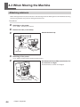
4-3 When Moving the Machine....................................................................80
Attaching retainers.........................................................................................................................80
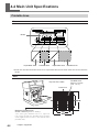
4-4 Main Unit Specifications.........................................................................82
Printable Area...................................................................................................................................82
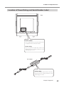
Location of Power Rating and Serial Number Label...........................................................83
Specifications....................................................................................................................................84
System Requirements for USB Connection............................................................................84
Windows® is a registered trademark or trademark of Microsoft® Corporation in the United States and/or other countries.
Company names and product names are trademarks or registered trademarks of their respective holders.
Copyright © 2011-2012 Roland DG Corporation
2
http://www.rolanddg.com
To Ensure Safe Use
Improper handling or operation of this machine may result in injury or damage to property.
Points which must be observed to prevent such injury or damage are described as follows.
About
WARNING and
WARNING
CAUTION Notices
Used for instructions intended to alert the user to the risk of death or severe injury
should the unit be used improperly.
Used for instructions intended to alert the user to the risk of injury or material
CAUTION
damage should the unit be used improperly.
* Material damage refers to damage or other adverse effects caused with respect to
the home and all its furnishings, as well to domestic animals or pets.
About the Symbols
The
symbol alerts the user to important instructions or warnings. The specific meaning
of the symbol is determined by the design contained within the triangle. The symbol at
left means "danger of electrocution."
The
symbol alerts the user to items that must never be carried out (are forbidden).
The specific thing that must not be done is indicated by the design contained within the
circle. The symbol at left means the unit must never be disassembled.
The
symbol alerts the user to things that must be carried out. The specific thing that
must be done is indicated by the design contained within the circle. The symbol at left
means the powercord plug must be unplugged from the outlet.
3
To Ensure Safe Use
Incorrect operation may cause injury
WARNING
Keep children away from the machine.
The machine includes areas and components that pose a hazard to children and
may result in injury, blindness, choking, or
other serious accident.
Install in a location that is level and
stable.
Installation in an unsuitable location may
cause an accident, including a fall or tip
over.
Never attempt to disassemble, repair, or
modify the machine.
Doing so may result in fire, electrical shock,
or injury. Entrust repairs to a trained service
technician.
Be sure to follow the operation procedures described in this documentation.
Never allow anyone unfamiliar with the
usage or handling of the machine to
touch it.
Incorrect usage or handling may result in
unexpected injury.
For accessories (optional and consumable items, power cord, and the like), use
only genuine articles compatible with
this machine.
Incompatible items may lead to an accident.
Never use the machine for any purpose
for which it is not intended, or use the
machine in an undue manner that exceeds its capacity.
Doing so may result in injury or fire.
4
CAUTION
To Ensure Safe Use
Danger of electrical short, shock, electrocution, or fire
WARNING
Connect to an electrical outlet that complies with this machine’s ratings (for
voltage, frequency, and current).
Incorrect voltage or insufficient current may
cause fire or electrical shock.
Never place any flammable object
nearby. Never use a combustible aerosol
spray nearby. Never use in any location
where gases can accumulate.
Combustion or explosion may be a danger.
Handle the power cord, plug, and electrical outlet correctly and with care. Never
use any article that is damaged.
Using a damaged article may result in fire
or electrical shock.
Ratings
Do not use with any power supply other
than the dedicated AC adapter.
Use with any other power supply may lead
to fire or electrocution.
Never use out of doors or in any location where exposure to water or high
humidity may occur. Never touch with
wet hands.
Doing so may result in fire or electrical
shock.
Never allow any foreign object to get
inside. Never expose to liquid spills.
Inserting objects such as coins or matches
or allowing beverages to be spilled into
the ventilation ports may result in fire or
electrical shock. If anything gets inside,
immediately disconnect the power cord
and contact your authorized Roland DG
Corp. dealer.
When using an extension cord or power
strip, use one that adequately satisfies
the machine’s ratings (for voltage, frequency, and current).
Use of multiple electrical loads on a single
electrical outlet or of a lengthy extension
cord may cause fire.
When the machine will be out of use
for a prolonged period, disconnect the
power cord.
This can prevent accidents in the event of
current leakage or unintended startup.
Position so that the power plug is within
immediate reach at all times.
This is to enable quick disconnection of the
power plug in the event of an emergency.
Install the machine next to an electrical
outlet. Also, provide enough empty space
to allow immediate access to the electrical
outlet.
If sparking, smoke, burning odor, unusual sound, or abnormal operation
occurs, immediately unplug the power
cord. Never use if any component is
damaged.
Continuing to use the machine may result in
fire, electrical shock, or injury. Contact your
authorized Roland DG Corp. dealer.
5
To Ensure Safe Use
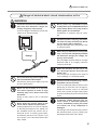
Important notes about the power cord, plug, and electrical outlet
Never place any object on top
or subject to damage.
Never allow to get wet.
Never bend or twist with undue force.
Never make hot.
Never pull with undue force.
Dust may cause fire.
Never bundle, bind, or roll up.
6
To Ensure Safe Use
The head area becomes hot
WARNING
Never touch the head immediately after
printing has finished.
Doing so may cause burns.
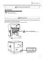
Warning Label
Warning label is affixed to make areas of danger immediately clear. The meaning of the label is
as follows. Be sure to heed its warnings.
Also, never remove the label or allow it to become obscured.
Caution: High Temperature
Never touch immediately after printing.
7
Important Notes on Handling and Use
This machine is a precision device. To ensure the full performance of this machine, be sure to
observe the following important points. Failure to observe these may not only result in loss of
performance, but may also cause malfunction or breakdown.
This Machine is a Precision Device.
Handle carefully, and never subject the machine to impact or excessive force.
Never print material outside the range of specifications.
Install in a Suitable Location
Install in a location having the specified temperature and relative humidity.
Install in a quiet, stable location offering good operating conditions.
Never use the machine in an environment where silicone substances (oil, grease, spray, etc.) are present.
Doing so may cause poor switch contact.
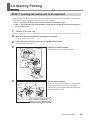
When Moving the Machine
When moving the machine, be sure to support it at the bottom using two hands. Attempting to move the
machine by holding it at a different location may result in damage.
When moving the machine to another location, be sure to attach the retainers. Attempting moving without
attaching the retainers may result in damage.
Printing
Never attempt to perform printing on the edges or over holes in printing material.
Printing results may vary according to the original data, the material printed, and the details of settings.
Before you perform actual printing, we recommend carrying out test printing.
Attempting printing with no material loaded may damage the pin or heads.
8
About Operation Manuals
Documentation Included with the Machine
The following documentation is included with the machine.
MPX-90M User’s Manual (this manual)
This describes important notes for ensuring safe use, and explains how to install and operate the machine. It
also explains how to install and operate included software.
Be sure to read it first.
METAZA Driver Online Help
Roland METAZAStudio Online Help
Roland SFEdit2 Online Help
You view this documentation on your computer screen. Installing the respective programs makes these available for viewing. They describe in detail the commands used in the programs.
P. 22, “How to Open the METAZA Driver Help,” p. 23, “How to display help for software”
9
10
Chapter 1
Getting Started
1-1 About the Machine..................................................................12
Features.....................................................................................12
Names of Components...............................................................12
Checking the Included Items......................................................14
1-2 Installation...............................................................................15
Installation Environment.............................................................15
Removing and storing the retainers...........................................15
Power Cord Connection.............................................................16
1-3 Installing the Software............................................................17
System Requirements................................................................17
The Software You Can Install and Set Up..................................17
Installing the Driver and the Software........................................18
11
1-1 About the Machine
Features
This machine is a direct marking printer. It prints images by striking detailed points using a marking pin
mounted in a head.
You can print Data Matrix ECC200 and QR codes on small steel objects used for medical purposes. Even when
printing different multiple codes in a row, you can continue printing without stopping to enter data for each
instrument to be imprinted (Variable Printing).
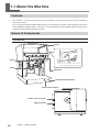
Names of Components
This Machine
Cover
Knob
Hold the middle area of the
cover when opening the cover.
Head
Head unit
Power/Movement button
Laser pointer button
Power-code connector
USB connector
12
Chapter 1 Getting Started
1-1 About the Machine
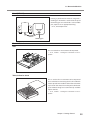
Head (MPH-90)
Printing is performed on material using with a
marking pin. Diamond is attached to the tip of
the marking pin. Since the head is a consumable
part, replace it at an appropriate timing.
P. 52, “Head Replacement”
Marking pin
Material Retainers
Vise
This is used to fix an instrument to be imprinted.
P. 35, "STEP 1: Loading the Instrument to be Imprinted"
Table, Adhesive sheet
This is used to fix an instrument to be imprinted
that cannot be secured using the vise. The adhesive
sheet is placed on the table and then the instrument
is placed on the sheet. This makes you to fix the objects without having to use commercially available
tape or the like.
P. 35, "STEP 1: Loading the Instrument to be Imprinted"
Chapter 1 Getting Started
13
1-1 About the Machine
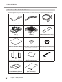
Checking the Included Items
The following items are packed together with the unit. Make sure they are all present and accounted for.
14
AC adapter (1)
Power cord (1)
USB cable (1)
Vise (1)
Table (1)
Adhesive sheet for vise (1)
(Installed on the vice by default)
Adhesive sheet for table (1)
Head caps (round bottom) (10)
(One installed on the unit by
default)
Head caps (flat bottom) (10)
Head (MPH-90) (1)
(Installed on the unit by default)
Test-use printing material (4)
(Brass-plated plates)
Hexagonal wrench (1)
Roland Software Package
CD-ROM (1)
User’s manual (1)
(This document)
Chapter 1 Getting Started
1-2 Installation
Installation Environment
Install in a quiet, stable location offering good operating conditions. An unsuitable location can cause accident,
fire, faulty operation, or breakdown.
CAUTION
Install in a location that is level and stable.
Installation in an unsuitable location may cause an accident, including a fall
or tip over.
Never install in a location subject to wide fluctuations in temperature or humidity.
Never install in a location subject to shaking or vibration.
Never install in a location where the floor is tilted, not level, or unstable.
Never install in a dusty or dirty location, or out of doors.
Never install in a location exposed to direct sunlight or near air-conditioning or heating equipment.
Never install in a location exposed to considerable electrical or magnetic noise, or other forms of electromagnetic energy.
Never install in an environment where silicone substances (oil, grease, spray, etc.) are present.
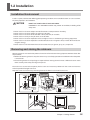
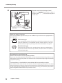
Removing and storing the retainers
Retaining materials are attached to protect the machine from vibration during shipment. Remove these after
emplacement.
Remove all Retaining materials. Any that remain may cause faulty operation or breakdown when the power
is switched on.
The retaining materials and package are required when moving the machine to a different location. Store
them carefully so that they do not get misplaced.
The machine is secured at three points (with 5 screws and 2 retainers). Remove all the screws and retainers
with the provided hexagonal wrench.
Keep the screws and retainers by mounting them to the lower back side of the machine.
Removing
Retainer
Hexagonal
wrench
Retainer
Storing
Chapter 1 Getting Started
15
1-2 Installation
Power Cord Connection
At this time, the connection to the computer must not be made yet.
Failure to follow the correct procedure may make installation impossible. You make the connection
to the computer when you install METAZA driver.
P. 18, “Installing the Driver and the Software”
WARNING
Do not use with any electrical power supply that does not meet the ratings
displayed on the AC adapter.
Use with any other power supply may lead to fire or electrocution.
WARNING
AC Never use any AC adapter and power cord other than the AC adapter
and power cord included with the machine.
Doing so may lead to fire, electrical shock, or electrocution.
WARNING
Handle the power cord, plug, and electrical outlet correctly and with care.
Never use any article that is damaged.
Using a damaged article may result in fire or electrical shock.
WARNING
When using an extension cord or power strip, use one that adequately
satisfies the machine’s ratings (for voltage, frequency, and current).
Use of multiple electrical loads on a single electrical outlet or of a lengthy
extension cord may cause fire.
Electrical
outlet
Power cord
AC adapter
Machine
DO NOT connect a USB cable at this point.
16
Chapter 1 Getting Started
1-3 Installing the Software
System Requirements
Operating system *
Windows XP/Vista/7 (32 bit edition/64 bit edition)
Processor
Intel® Core 2 Duo or greater (Core i5 or greater recommended)
Memory
1 GB or greater (2 GB or more recommended)
Optical drive
CD-ROM drive
Video card and monitor
At least 16 bit colors (High Color) with a resolution of 1024 x 768 or
more recommended
Free hard-disk space required for installation
25 MB
* As this software is a 32-bit application, it runs on WOW64 (or Windows-On-Windows 64) under the 64-bit
version of Windows.
For the latest information, see the Roland DG Corp. website (http://www.rolanddg.com).
The Software You Can Install and Set Up
METAZAStudio
This is a program for creating printing data.
It enables you to import and print 2D symbol (QR code and the like) data.
It also enables you to edit and create 2D symbol, directly enter text, and
perform Variable Printing (even when printing different multiple codes
in a row, you can continue printing without stopping to enter data for
each instrument to be imprinted.)
SFEdit2
This is a program that lets you create and edit stroke fonts. Stroke fonts
are line drawings created by automatically extracting the centerlines
from a TrueType font. You can use the generated stroke fonts as fonts
with METAZAStudio.
MPX-90M Head Manager
This is a utility for adjusting the head. Run it when you replace the head
or adjust the marking pin.
METAZA Driver
This is a Windows-based driver required for sending data from a computer to the machine.
Chapter 1 Getting Started
17
1-3 Installing the Software
Installing the Driver and the Software
Make sure to connect the machine to a computer by following the given procedure.
Failure to follow the correct procedure may make installation impossible.
Procedure
Before you start installation and setup, make sure the USB cable is NOT connected.
Log on to Windows as “Administrators.”
Insert the Roland Software Package CD-ROM into the computer.
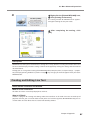
Windows Vista/7: When the automatic playback window appears, click [Run menu.exe].
The install menu appears automatically.
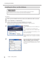
Click [Install].
Install the METAZA driver and each software at a
time.
P. 17 "The Software You Can Install and Set Up"
You can install the driver and each software separately.
P. 72, "To install METAZA driver separately", P. 76 "To
Install Software Separately".
When using Windows Vista or Windows 7: If the [User
Account Control] screen is displayed, click [Allow]
or [Yes].
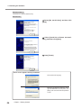
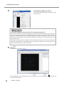
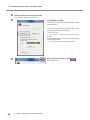
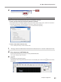
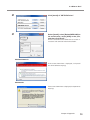
Select [Install], Model name [Roland MPX90M], Port [USB], and then click [Start].
Installation of the METAZA driver starts. Proceed
with the installation by following the on-screen
instructions.
18
Chapter 1 Getting Started
1-3 Installing the Software
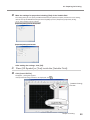
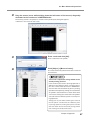
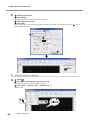
Windows Vista / 7:
If the screen shown in the figure appears, click [Install this
driver software anyway].
Windows XP:
If the screen shown in the figure appears, click [Continue
Anyway].
Follow the on-screen instructions and continue with the installation.
When installation is complete, click
Installation information for each software item will be displayed automatically as needed.
in the installation menu.
Remove the Roland Software Package CD-ROM from the computer.
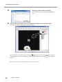
Switch on the power to the machine.
P. 27, “STEP 1: Switching On the Power”
Connect the machine to the computer by USB cable.
Never connect two or more machines to one computer.
Use the supplied USB cable.
Do not use a USB hub.
Chapter 1 Getting Started
19
1-3 Installing the Software
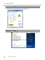
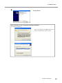
Windows Vista / 7:
The driver is installed automatically.
Windows XP:
Select [No, not this time], and then click
[Next].
Select [Install the software automatically], and then click [Next].
Click [Finish].
If this screen appears during installation
Click [Continue Anyway].
Remove the Roland Software Package CD-ROM from the computer, click
[Back], and start over from the previous
screen.
20
Chapter 1 Getting Started
1-3 Installing the Software
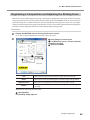
How to Open the METAZA Driver's Printing Preferences Screen
Procedure
From [start] menu (
), click [Devices and
Printers] (or [Printers and Faxes]).
Right-click the [Roland MPX-90M] icon, and
then click [Printing Preferences].
The METAZA driver's Printing Preferences screen
opens.
Printing Preferences dialog box
Chapter 1 Getting Started
21
1-3 Installing the Software
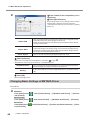
How to Open the METAZA Driver Help
Open the METAZA driver's Printing Preferences screen, and then click [Help].
P. 21 "How to Open the METAZA Driver's Printing Preferences Screen"
How to Start The Software
From start menu (
22
), click [All Programs] → [software you want to use] → [software you want to use].
Chapter 1 Getting Started
1-3 Installing the Software
How to display help for software
Start the software, and then click [Help] → [Table of Contents] from the menu.
P. 22, "How to Start The Software"
Chapter 1 Getting Started
23
24
Chapter 2
Printing
2-1 Preparing for Printing..............................................................26
Getting Started: Checking Print Workflow..................................26
STEP 1: Switching On the Power...............................................27
STEP 2: Specifying Output Destination for METAZAStudio.......28
STEP 3: Preparing Instrument to be Imprinted...........................28
STEP 4: Preparing Print Data.....................................................30
2-2 Starting Printing......................................................................35
STEP 1: Loading the Instrument to be Imprinted.......................35
STEP 2: Making Prints...............................................................43
STEP 3: Finishing Printing (Switching Off the Power)................45
2-3 Finishing and Stopping Printing Operations...........................46
Stopping Printing Operations.....................................................46
Deleting Data from Print Queue ................................................46
25
2-1 Preparing for Printing
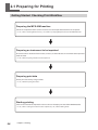
Getting Started: Checking Print Workflow
Preparing the MPX-90M machine
Switch on the power of the machine and select it as the output destination for the computer.
P. 27, "STEP 1: Switching On the Power," p. 28, "STEP 2: Specifying Output Destination for METAZAStudio"
Preparing an instrument to be imprinted
Check the several conditions for thickness, hardness, and the like that an instrument to be imprinted
needs to meet.
P. 28, "STEP 3: Preparing Instrument to be Imprinted"
Preparing print data
Create print data mainly using CSV files.
P. 30, "STEP 4: Preparing Print Data"
Starting printing
Set the instrument to be imprinted in the machine and output print data from METAZAStudio.
P. 35, "STEP 1: Loading the Instrument to be Imprinted" p. 43, "STEP 2: Making Prints"
26
Chapter 2 Printing
2-1 Preparing for Printing
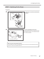
STEP 1: Switching On the Power
Procedure
Stopper
Open the cover and loosen the head's
stopper.
Tighten
Press the Power/Movement button.
The Head moves to the left rear, and the lamp of the
Power/Movement button is turned ON. This operation is called initialization.
Power/Movement button
When the power lamp remains blinking
An initialization error. Loosen the stopper of the head, and then press the Power/Movement button.
The error is cleared, and the power lamp is lit.
Chapter 2 Printing
27
2-1 Preparing for Printing
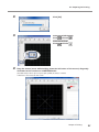
STEP 2: Specifying Output Destination for METAZAStudio
Procedure
Start METAZAStudio.
P. 22, "How to Start The Software"
Click [File] → [Set up the printer].
The [Print Setup] dialog box appears.
Select [MPX-90M].
Click [OK].
STEP 3: Preparing Instrument to be Imprinted
The requirements for the instrument to be imprinted by the machine are described below. The instrument
needs to meet all these requirements.
Thickness
Using vise : 0.3 to 20 mm (0.012 to 0.8 in.)
Using table : 0.3 to 40 mm (0.012 to 1.5 in.)
Size
The instrument is large enough to be firmly secured.
The machine uses the vise or adhesive sheet to secure the instrument to be imprinted. Though it is accepted
even if the size of the instrument is the one to protrude from the vise or adhesive sheet, the essential requirement is that the instrument can be firmly secured.
28
Chapter 2 Printing
2-1 Preparing for Printing
Hardness of surface to print
Hardness of surface to print Vickers hardness (HV) of 200 or less
Materials which may crack or split by printing (such as glass, stone, precious stones, china, and porcelain)
cannot be printed even if hardness is within the preceding range.
Attempting to print such materials may damage the machine.
Vickers hardness (HV) is used as a yardstick to represents the hardness of industrial materials. For the information on the hardness of the instrument to be imprinted, please contact the shop where you bought the
instrument or its manufacturer.
Surface form
The instrument must not have the surface form described below.
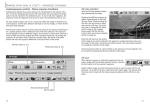
The surface to be imprinted is uneven, and the surface comes into contact with the moving
part of the machine when material is set or when printing is made.
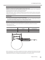
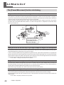
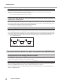
Conditions for Material When Printing Curved Surfaces
The table and figure below show the printing-assured area and the area reached by the marking pin with
respect to the diameter of the cylinder. Note, however, that the following conditions are assumed.
The head cap is used.
The material has circularity.
Diameter of cylindrical material
10 mm (0.3 in.)
20 mm (0.7 in.)
30 mm (1.1 in.)
Recommended printable
area (A)
2.0 mm (0.079 in.)
2.8 mm (0.11 in.)
3.4 mm (0.14 in.)
Area reached by the
marking pin (B)
2.8 mm (0.11in.)
4.0 mm (0.16 in.)
4.8 mm (0.19 in.)
Note : For printing on curved surfaces, regardless of the shape or composition of the material, the image
quality of photographic data cannot be assured. For printing on curved surfaces, regardless of the shape or
composition of the material, the image quality of photographic data cannot be assured.
Chapter 2 Printing
29
2-1 Preparing for Printing
STEP 4: Preparing Print Data
The method of preparing print data for [Variable Printing] is explained below. Variable Printing needs a CSV
file. You can create a CSV file using database files. For information on creating a CSV file, contact the administrator of databases.
What you print is [Text] or [2D Symbol]. "Data Matrix" or "QR code" is selectable as 2D symbol.
What is Variable Printing?
In the [Variable Printing], you can replace a part of print data with new one for each sheet and print
each different object. When you use Variable Printing, you no longer need to create new data each
time when you load a small steel medical object. You can continue to print different data without
interruption.
* You can create 2D symbol directly from METAZAStudio instead of a CSV file.
P. 56, "Directly Creating 2D Symbol"
1.
Create [Variable Field].
What is [Variable Field]?
Variable field is a frame in which you can place 2D symbol or text. In Variable Printing, data within the
variable field is replaced with other one during printing.
Start METAZAStudio.
P. 22, "How to Start The Software"
The [Select Material] dialog box appears.
If METAZAStudio is running, click Image
.
The [Select Material] dialog box appears.
In the [Select Material] dialog box, select the
material of the instrument to be imprinted.
Uncheck the [Use printer driver settings] checkbox
to select a type of material. To use material that is not
included in the list, you can register the material.
P. 59, "Registering a Composition and Adjusting the
Striking Force"
If you use the driver's setting without changing it,
check the [Use printer driver settings] checkbox.
30
Chapter 2 Printing
2-1 Preparing for Printing
Click [OK].
In the case of [2D Symbol]
Click
and then
.
In the case of [Text]
Click
and then
.
Drag the mouse (move while holding down the left button of the mouse) diagonally
downward on the work area* in METAZAStudio.
[Variable Field] in which you can place [2D Symbol] or [Text] is created.
* Work area = black area on the screen
Chapter 2 Printing
31
2-1 Preparing for Printing
Click [Object] > [Move to Center].
The center of the Variable field moves to the center
of the work area.
This work is important, being related to the actual printing position.
In the machine, the center in printing operation is defined as the reference point in printing operation. The "center of the work area" in METAZAStudio coincides with the reference point in printing
operation. Consequently, making the "center of the Variable field" coincide with the center of the
work area means making the "center of the Variable field" coincide with the "reference point in actual
printing operation."
Though you can print without making the center of the [Variable Field] coincide with the "reference
point in printing operation, "making these points coincide with each other ensures the ease of placing
printed text and image at the desired location.
Click
.
The [Properties] dialog box appears.
If the Variable field is not selected, you cannot click
(select) the Variable field.
32
Chapter 2 Printing
. If you cannot click
, click
and then click
2-1 Preparing for Printing
Make the settings for properties including [Size] of the Variable field.
The setting items you can specify are different between [2D Symbol] and [Text]. For details on each setting,
refer to the help for METAZAStudio ([Commands]-[Object] menu-[Properties]-[Properties] dialog.
P. 23, "How to Display Help for Software"
[Properties] dialog box for 2D symbol
[Properties] dialog box for text
2.
After making the settings, click [OK].
Place [2D Symbol] or [Text] inside the [Variable Field].
Click [Load CSV File].
The [Open...] dialog box appears.
If the [Variable Printing] window is not displayed, click
.
[Variable Printing]
window
Chapter 2 Printing
33
2-1 Preparing for Printing
Specify a CSV file and click [Open].
Drag and drop the column title of the imported CSV file into the [Variable Field]
The specified CSV file is imported into METAZAStudio.
[2D Symbol] or [Text] is displayed in the [Variable Field].
. If you want to change the size or location of
You can display each symbol in turn by clicking
the Variable Field or the cell size of the 2D symbol, open the [Properties] dialog box
and change the
settings.
Now the print data is prepared. Go to "2-2 Starting Printing" in P. 35.
34
Chapter 2 Printing
2-2 Starting Printing
STEP 1: Loading the Instrument to be Imprinted
Decide whether you use the vise or table as a retainer depending on the size or shape of the instrument to be
imprinted. The criteria used to select the vise or table are as follows:
Vise The size and shape of the instrument that can be fixed by vise.
Table The instrument has a flat bottom and the size and shape of the instrument that can
not be fixed by vise.
1.
Attach the head cap.
Make sure that preparations for printing are completed.
P. 26, "2-1 Preparing for Printing"
If the head unit is lowered, press the Power/Movement button.
The head moves to the left rear.
Ring
Loosen the head's stopper.
The stopper and ring contact each other.
Stopper
Loosen
Fix the head's stopper.
Knob
Tighten
Align the center of the knob with the top of the triangle right below and then secure the stopper.
If you printing as the stopper is loose, the knob might
come off due to vibration.
The center of the knob must
be positioned immediately
above the top of the triangle.
Chapter 2 Printing
35
2-2 Starting Printing
Attach a head cap to the tip of head.
Hold the head.
Mount it as lightly holding the head as shown in
Tighten
the figure. The head
cap is attached correctly when
its tab clicks.
Head
Head cap
About the shape of head cap
There are two different types of head caps with a different shape. Select the one appropriate for a
printing surface.
Flat bottom type
This is suitable for printing on a flat surface. As this head cap cannot track a curved
surface or slope well, it is unsuitable for printing on these surfaces. It has high
abrasion resistance against a printing surface and can be used for a long time.
Round bottom type
As this head cap can easily track a curved surface or slope, it is suitable for printing on these surfaces. This head cap, however, tends to be worn out compared
to the flat bottom type.
Precautions for use of head cap
Remove dirt and dust from the printing surface.
If you carry out printing without removing dirt and dust attached to the printing surface, it may
deteriorate the printing quality. Make sure to remove dirt and dust from the printing surface before
you perform printing.
For test printing, it is advisable to use materials with no scratches or stains.
Some materials may cause scratches and stains on the head cap during printing, which may affect
the printing quality. Scratches and stains on the materials may also damage the head cap and result
in poor-quality printing. Therefore, for your prior checks on printing, we recommend you perform
test printing with materials without any scratches or stains.
36
Chapter 2 Printing
2-2 Starting Printing
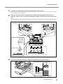
2.
Load the instrument to be imprinted on the vise.
When using the table, go to P. 40.
Push the rear side of the vise (where the handle is placed) against the main unit.
Align the sides of the vise with the alignment marks and lower the front side of the
vise.
When the tabs on the bottom of the vise fit into the holes on the unit, this completes mounting of the
vise.
Handle
Alignment mark
Turn the fine adjustment dial to align the sides of the layers of the table.
Table
Fine adjustment
dial
Chapter 2 Printing
37
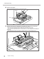
2-2 Starting Printing
Raise the vise binder.
When raising or lowering the binder, be sure to hold its handle.
Handle
Binder
Place the instrument to be imprinted on the table of the vise and lower the binder.
Follow the instructions below and determine the position of the instrument.
The area to be imprinted must be within the resin sheet on the table.
The area to be imprinted must be 10 mm (0.39 in.) or more away from the outline of
the binder.
The instrument must be secured in a manner that you cannot easily move it.
38
Chapter 2 Printing
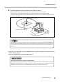
2-2 Starting Printing
Press the laser pointer button.
The laser pointer is irradiated.
If the machine is idle for 5 minutes, the laser pointer
is automatically turned off.
Laser pointer button
Raise the lock lever.
Move the table so that the laser pointer points at the center of the area to be imprinted.
To finely adjust the table position, use the fine adjustment dial. The table position is adjustable within
the range of ± 2 mm (0.08 in.).
The position to which the laser pointer points coincides with the center of the work area in METAZAStudio. By making the position to which the laser pointer points coincide with the center of the area to
be imprinted, you can print with the exactly same layout as the one displayed on the METAZAStudio's
work area.
Lower the lock lever.
Laser pointer
Lock lever
The area to be imprinted
Fine adjustment dial
If you print using the head cap, this completes loading of the instrument to be imprinted. Go to
"STEP 2: Making Prints."
If you use no head cap, go to Step 3. in P. 42.
Chapter 2 Printing
39
2-2 Starting Printing
2.
Load the instrument to be imprinted on the table.
When using the vise, go to P. 37.
Set the table.
Place the table by aligning it with the frame on the unit. When the tabs on the bottom of the table fit into
the holes on the unit, this completes setting of the table.
Table
Table
Affix the adhesive sheet for table to the
table.
Place the adhesive sheet straight inside the table
frame by aligning it with the scale marks. Be careful
not to allow any air bubbles to form between the
table and adhesive sheet.
If the adhesive force has been educed, then
Adhesive sheet for table
wash the adhesive sheet.
☞ P. 48, "Cleaning the Adhesive Sheet"
Never rub the surface with force. Doing so
may damage the surface and reduce its
adhesive strength.
Press the laser pointer button.
The laser pointer is irradiated.
If the machine is idle for 5 minutes, the laser pointer
is automatically turned off.
Laser pointer button
40
Chapter 2 Printing
2-2 Starting Printing
Load the instrument to be imprinted on the adhesive sheet.
Move the table so that laser pointer points at the center of the area to be imprinted.
Gently press the instrument to be imprinted in a way that you affix it to the adhesive sheet.
If the instrument protrudes from the table and the instrument tilts, place a support in order to keep the
instrument horizontal.
Laser pointer
The area to be imprinted
The position to which the laser pointer points coincides with the center of the work area in METAZAStudio. By making the position to which the laser pointer points coincide with the center of the area to
be imprinted, you can print with the exactly same layout as the one displayed on the METAZAStudio's
work area.
If you print using the head cap, this completes loading of the instrument to be imprinted. Go to
"STEP 2: Making Prints."
If you use no head cap, go to the following step 3..
Using the head cap is usually recommended.
When the head cap is used, the machine automatically tracks the surface height of material and sets
the position of the head. You can make a print on a curved surface. (There is an upper limit of the
height that can be tracked.) It is recommended to use the head cap for usual printing.
Chapter 2 Printing
41
2-2 Starting Printing
3.
Fix the height of the head. (Only when no head cap is used)
Press the Power/Movement button.
The head moves and stops at the position where the tip of the head cap rides on the surface of the
instrument to be imprinted.
Power/Movement
button
Loosen the head's stopper.
Loosen
Lower the stopper to the bottom.
Fix the stopper.
Align the center of the knob with the top of the
triangle right below.
The center of the knob must
be positioned immediately
above the top of the triangle.
42
Chapter 2 Printing
2-2 Starting Printing
Press the Power/Movement button.
The head moves to the left rear.
Power/Movement button
Detach the head cap.
Support the head
Head cap
Putting your fingers on the
projecting rim of the head
cap eases removal.
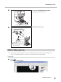
STEP 2: Making Prints
After you complete "Preparing for Printing" and "Loading Instrument to be Imprinted," printing starts.
P. 26, "2-1 Preparing for Printing," p. 35, "STEP 1: Loading the Instrument to be Imprinted"
Procedure
Click
.
The [Print] dialog box appears.
Chapter 2 Printing
43
2-2 Starting Printing
Set and confirm the preferences below.
Printer
name
Roland MPX-90M
Printing
range
To restrict records (individual data included in a set of data used in Variable Printing)
to be printed, specify the record (page) that you wish to print. For example, if you print
the records of 2nd to 5th only, select [Pages] and specify the "2nd" to "5th" pages.
Copies
If you imprint the same instrument at multiple locations, specify multiple number of
copies. For example, if you wish to print on the front and back sides of the instrument,
specify "2" as the number of copies.
Material
Select the material of the instrument to be imprinted and specify your priority on
printing quality (priority of quality or speed). The selection you make when you create new print data is reflected in the material setting. You can change the setting to
print. The setting here takes priority over the setting in the METAZA driver.
Click [OK].
Printing starts.
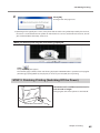
When you print multiple pages or multiple copies, the message shown in the figure appears after
printing starts.
Wait until printing is finished, and then go on to the
next step.
When printing is finished, replace the instrument (material) to be printed or change
its orientation.
P. 35, "STEP 1: Loading the Instrument to be Imprinted"
Make sure to align the position using the laser pointer button.
44
Chapter 2 Printing
2-2 Starting Printing
Click [OK].
Printing of the next page starts.
* Depending on the type of your scanner, it may be unable to read the 2D symbol imprinted by the machine,
because it is unsuitable for the 2D symbol. For information on scanners suitable for the machine, consult
your authorized Roland DG Corp. dealer or us.
When you wish to print only the record being displayed:
Click
.
The [Print] dialog box appears.
The number (page number) of the record being displayed in METAZAStudio is specified as the page for
[Print Range]. Specify [Material] and [Copies] as necessary and click [OK] to start printing.
STEP 3: Finishing Printing (Switching Off the Power)
Hold down the Power/Movement button for
one second or longer.
The light goes dark and the power is switched off.
Power/Movement button
Chapter 2 Printing
45
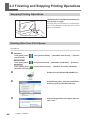
2-3 Finishing and Stopping Printing Operations
Stopping Printing Operations
Hold down the Power/Movement button for
one second or longer.
The light slowly blinks while the transmitted print
data is being deleted. The light goes dark and the
power is switched off.
Power/Movement button
Deleting Data from Print Queue
Procedure
Windows 7
From [start] menu (
and Printers].
Windows Vista
From [start] menu (
Windows XP
From [start] menu (
[Printers and Faxes].
46
), click [Control Panel] → [Hardware and Sound] → [Devices
), click [Control Panel] → [Hardware and Sound] → [Printers].
), click [Control Panel] → [Printers and Other Hardware] →
Double-click the [Roland MPX-90M] icon.
At the [Printer] menu, click [Cancel All Documents] (or [Purge Print Documents]).
If the message shown in the figure appears,
click “Yes.”
Chapter 2 Printing
Chapter 3
Maintenance and Adjustment
3-1 Maintenance and Adjustment.................................................48
Points to Note on Daily Care......................................................48
Cleaning the Body/Vise/Table.....................................................48
Cleaning the Adhesive Sheet.....................................................48
Cleaning of the Head Cap..........................................................48
3-2 Adjustment..............................................................................49
Adjusting the Striking Force of the Pin.......................................49
Adjustment of Origin Point..........................................................50
3-3 The Replacement of the Consumable Parts...........................51
The Replacement Cycle for the Head Cap.................................51
Head Replacement.....................................................................52
47
3-1 Maintenance and Adjustment
Points to Note on Daily Care
WARNING
Never use gasoline, alcohol, thinner, or any other flammable material.
Doing so may cause fire.
CAUTION
Never touch the heads immediately after printing has finished.
Doing so may cause burns.
This machine is a precision device, and is sensitive to dust and dirt. Be sure to carry out day-to-day cleaning.
Never use solvents such as thinner, benzine, or alcohol.
Never attempt to oil or lubricate the machine.
Never apply silicone substances (oil, grease, spray, etc.) to the machine. Doing so may cause poor switch
contact.
Cleaning the Body/Vise/Table
Use a cloth moistened with water then wrung well, and wipe gently to clean.
The surface of the cover is easily scratched, so use a soft cloth.
Cleaning the Adhesive Sheet
Attaching dust or the like on the adhesive sheet can reduce the sheet's adhesive force, making it difficult to
secure an instrument to be imprinted in place. If the adhesive force has been reduced, then wash the adhesive
sheet.
How to Wash
Immerse the adhesive sheet in water, and wash the sheet by gently stroking its surface. If the soiling of the
adhesive sheet is severe, wash it using diluted neutral detergent. Rinse thoroughly with water to remove all
detergent completely.
Be sure to comply with the following instructions.
If not, the surface of the adhesive sheet is damaged, lowering the adhesiveness.
Never scrub the adhesive sheet using a scrubbing pad or sponge.
Never stretch or bend the adhesive sheet when washing it.
How to DRY
Allow to dry completely, out of direct sunlight.
Cleaning of the Head Cap
Detach the head cap from the machine and remove dirt and dust from the surface and the inside of the head
cap. Printing without removing dirt and dust from the head cap may damage instruments to be imprinted
and/or affect the print quality.
48
Chapter 3 Maintenance and Adjustment
3-2 Adjustment
Adjusting the Striking Force of the Pin
You can adjust the striking force of the pin by using MPX-90M Head Manager. Pin adjustment involves striking
the pattern shown in the figure. Prepare a piece of test-use printing material (brass) or other material measuring about 60 mm (2.3 in.) by 60 mm (2.3 in.).
Adjustment pattern
Procedure
Start MPX-90M Head Manager.
P. 22, "How to Start The Software"
Switch on the power to the machine.
P. 27, "STEP1: Switching On the Power"
Click [Readjust Pin].
Follow the on-screen instructions to perform adjustment for the pin.
Set a material to be imprinted with a test pattern
using the adhesive sheet and table.
Use a head cap.
P. 35, "STEP 1: Loading the Instrument to be Imprinted"
If the adjustment pattern fails to be printed, see the
sections given below.
P. 67, "The printed location isn't where desired"
When you have finished, click
The window closes.
Chapter 3 Maintenance and Adjustment
.
49
3-2 Adjustment
Adjustment of Origin Point
If printed text or image is placed at a position that does not coincide with the desired position, the origin point
of the machine is displaced. Adjust the origin point using the method described below.
Procedure
Start MPX-90M Head Manager.
P. 22, "How to Start The Software"
Click [Adjust Origin].
The [Adjust Origin] wizard appears.
MPX-90M Head Manager
Follow the on-screen instructions to perform adjustment.
[Adjust Origin] wizard
50
Chapter 3 Maintenance and Adjustment
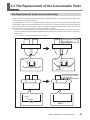
3-3 The Replacement of the Consumable Parts
The Replacement Cycle for the Head Cap
When the head cap becomes worn away as shown in the figure below, it is time for replacement. Replace the
head cap with a new one appropriately.
The degree of wear may vary according to printing conditions. In particular, printing that makes extensive use
of island fill and other line-drawing operations on materials such as aluminum results in especially rapid wear
because of the extensive unevenness on the surface of the instrument to be imprinted. Periodically check the
state of the head cap to ensure that it is replaced as often as needed.
* "Island fill" is a method of printing characters and objects (without filling objects) using lines placed at intervals. For details, refer to the help for METAZAStudio ("Commands"-"[Format] menu"-"Font"-"[Properties]
dialog box").
P. 35, "STEP 1: Loading the Instrument to be Imprinted"
Head cap which needs
to be replaced
Tabs
Tabs
Abraded
Head cap which needs
to be replaced
Groove
Abraded
Chapter 3 Maintenance and Adjustment
51
3-3 The Replacement of the Consumable Parts
Head Replacement
In the following cases, the head needs replacement.
The head reaches the end of its life.
The marking pin is worn out.
A General Guide of Head Life
About 4,000 plates can be printed under the following conditions.
Material used : MD-NI (Roland nickel-plated plate)
Printing area : 30 mm (1.1 in.) X 23 mm (0.9 in.)
Print Mode : Photo
Printing rate : 35% (25,000 dots per plate)
In the case of 2D symbol
About 60,000 to 100,000 symbols of 3 mm x 3 mm (H x W) size can be printed
* It depends on the setting of METAZAStudio.
A message that indicates the head life also appears on METAZAStudio.
Click [OK], and the message disappears. Click [Details], and MPX-90M Head Manager appears.
P. 52 "How to check the state of the marking pin"
How to check the state of the marking pin
You can check the state of the marking pin using MPX-90M Head Manager.
Procedure
52
Start MPX-90M Head Manager.
P. 22, "How to Start The Software"
Chapter 3 Maintenance and Adjustment
3-3 The Replacement of the Consumable Parts
Switch on the power to the machine.
P. 27, "STEP1: Switching On the Power"
The indicator for [The amount of Pin usage] in MPX90M Head Manager shows how much the marking
pin has been used. The following cases need head
replacement.
The indicator is shown in red.
Though the indicator is not shown in red,
attractive printing is unavailable or images
are uneven.
The worn-out of marking pin is not the only reason for decrease of print quality and uneven print
results. Refer to the pages below to find the cause
of the problem. If the worn-out of marking pin can
be the cause of the problem, replace the head with
a new one.
P. 69, "The printed image is unattractive," p. 69, "The
image is uneven"
This refreshes the screen to
display the latest information.
The amount of pin usage is indicated in this window.
The level indicator increases little by little as the pin
is used to strike the material. The rate of increase
varies depending on the material used for printing.
How to Replace the Head
MPX-90M Head Manager is used for the head replacement operation. The pattern shown in the figure is struck
during the head replacement operation. You need to prepare a test print material (brass), which is supplied
with a replacement head (MPH-90), or a material equal to or larger than 60 mm (2.3 in.) x 60 mm (2.3 in.).
Note : A replacement head is sold separately. Consult your authorized Roland DG Corp. dealer.
Adjustment pattern
Important
Do not stop the replacement operation halfway.
Do not use the head of which the marking pin is worn out.
Do not use the head which is detached from the machine.
Procedure
Start MPX-90M Head Manager.
P. 22, "How to Start The Software"
Chapter 3 Maintenance and Adjustment
53
3-3 The Replacement of the Consumable Parts
Switch on the power to the machine.
P. 27, "STEP1: Switching On the Power"
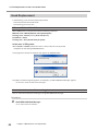
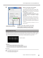
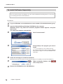
Click [Replace Head].
Follow the on-screen instructions to perform adjustment for the pin.
Set a material to be imprinted with a test pattern
using the adhesive sheet and table.
Use a head cap.
P. 35, "STEP 1: Loading the Instrument to be Imprinted"
If the adjustment pattern fails to be printed, see the
sections given below.
P. 67, "The printed location isn't where desired"
54
When you have finished, click
The window closes.
Chapter 3 Maintenance and Adjustment
.
Chapter 4
Appendix
4-1 More Advanced Operations....................................................56
Directly Creating 2D Symbol......................................................56
Registering a Composition and Adjusting the Striking Force.....59
Changing Basic Settings of METAZA Driver...............................60
Creating and Editing Line Text....................................................61
Other operations available with METAZAStuido.........................65
4-2 What to Do If...........................................................................66
The [Power/Movement] button is blinking. ................................66
The machine doesn't run even when printing data is sent.........67
The printed location isn't where desired.....................................67
You cannot select the material of the object to be imprinted using
METAZAStudio. .........................................................................68
The printed image is unattractive...............................................69
The image is uneven..................................................................69
The image is always faint at the same location..........................70
To install METAZA driver separately...........................................72
To Install Software Separately....................................................76
The METAZA Driver Cannot Be Installed...................................77
Uninstalling the METAZA driver..................................................78
4-3 When Moving the Machine.....................................................80
Attaching retainers......................................................................80
4-4 Main Unit Specifications.........................................................82
Printable Area.............................................................................82
Location of Power Rating and Serial Number Label..................83
Specifications.............................................................................84
System Requirements for USB Connection...............................84
55
4-1 More Advanced Operations
Directly Creating 2D Symbol
You can create 2D symbol not only from a CSV file but also directly from METAZAStudio.
Based on a 2D symbol you create, you can edit the code using METAZAStudio and create another 2D symbol.
Procedure
Start METAZAStudio.
P. 22, "How to Start The Software"
If METAZAStudio is running, click
.
In the [Select Material] dialog box, select the
material of the instrument to be imprinted.
Uncheck the [Use printer driver settings] checkbox
to select a type of material. To use material that is not
included in the list, you can register the material.
P. 59, "Registering a Composition and Adjusting the
Striking Force"
If you use the driver settings without changing them,
check the [Use printer driver settings] checkbox.
56
Click [OK].
Click
Chapter 4 Appendix
.
4-1 More Advanced Operations
Drag the mouse (move while holding down the left button of the mouse) diagonally
downward on the work area* in METAZAStudio.
The drawing area for a 2D symbol is created and the [Code Input] dialog box appears.
* Work area = black area on the screen
Enter a code and click [OK].
Click [Object] > [Move to Center].
Enter a code for the 2D symbol.
The center of the 2D symbol moves to the center of
the work area.
This work is important, being related to the
actual printing position.
In the machine, the center in printing operation is
defined as the reference point in printing operation. The "center of the work area" in METAZAStudio coincides with the reference point in printing
operation. Consequently, making the "center of the
2D symbol" coincide with the "center of the work
area" means making the "center of the 2D symbol"
coincide with the "reference point in actual printing operation."
Though you can print without making the "center of
the 2D symbol" coincide with the "reference point
in printing operation," making these points coincide
with each other ensures the ease of placing printed
text and image at the desired location.
Chapter 4 Appendix
57
4-1 More Advanced Operations
Click
.
The [Properties] dialog box appears.
If the drawing area for the 2D symbol is not selected, you cannot click
and then click (select) the drawing area for the 2D symbol.
. If you cannot click
, click
Make the settings for properties including [Size] of the 2D symbol.
For details on each setting, refer to the help for METAZAStudio ([Commands] - [Object] menu - [Properties] - [Properties] dialog box).
P.23, "How to display help for software"
After making the settings, click [OK].
If you click [Change] in the [2D Symbol]
tab, the [Code Input] dialog box appears.
Using the [2D Symbol] file you create
directly in METAZAStudio, you can create
a file with a different code.
Now the print data is prepared. Go to "STEP 1: Loading the instrument to be imprinted" in P. 35.
58
Chapter 4 Appendix
4-1 More Advanced Operations
Registering a Composition and Adjusting the Striking Force
With the machine, performing printing using a striking force appropriate to the material of the instrument
to be imprinted can obtain printing results of even higher quality. The METAZA driver for the machine has
premade settings for a number of materials and their appropriate striking forces, but you can also register
materials and their optimal striking forces yourself. You can also carry out later adjustment of the striking force
of materials you've registered yourself, in order to obtain better printing results.
Procedure
Display the METAZA driver's Printing Preferences screen.
P. 21, "How to Open the METAZA Driver's Printing Preferences Screen"
Click [Image Correction] tab.
For [Material], select a custom material
(settings a through).
Select print Mode.
Text
Photo
HighResolution
Others
When you want to print text and other images with clear outlines
When you want to print photographs and other images with gradation
When you want to express small text and small patterns clearly
When you want to make the resolution setting and other settings of
an image
METAZA Driver online help ([Correction] tab)
Click [Details].
The [Details] dialog appears.
Chapter 4 Appendix
59
4-1 More Advanced Operations
Enter a name for the composition you’re
registering.
Enter [Speed/Impact]
The printing results vary according to the hardness
of the material. Adjust to match the material.
METAZA Driver online help ("[Correction] tab" > "[Details]
dialog box")
Impact--MIN
You can set the minimum value of print impact for an image. Raise the
value when dark areas of the image are not struck.
Lower the value when dark areas of the image are whitish or when overall
striking is too forceful.
Impact--MAX
You can set the maximum value of print impact for an image. Raise the
value when bright areas of the image are struck with too little force or
when overall striking is too weak. Lower the value when bright areas of
the image are struck with too much force.
Vector Impact
You can set the maximum value of print impact for a line.
Select [Advance].
[Advance] is available only when [Other] is selected in
in step .
METAZA Driver online help ("[Correction] tab" > "[Details] dialog box")
OutputResolution
You can specify the number of dots per inch. As the number of the points
becomes larger, the image will become more precise.
Drafting
If you select "ON", you can skip image information in increments of one
dot.
Click [OK].
[Advance] dialogue close.
Changing Basic Settings of METAZA Driver
Procedure
Windows 7
From [Start] menu (
and Printers].
Windows Vista
From [Start] menu (
Windows XP
From [Start] menu
ers and Faxes].
60
Chapter 4 Appendix
), click [Control Panel] → [Hardware and Sound] → [Devices
), click [Control Panel] → [Hardware and Sound] → [Printers].
, click [Control Panel] → [Printers and Other Hardware] → [Print-
4-1 More Advanced Operations
Right-click the [Roland MPX-90M] icon,
Click [Printing Preferences].
The setting window for METAZA Driver appears.
Change the settings to suit your needs.
After completing the setting, click
[OK].
Description
METAZA Driver allows you to make the basic settings for a variety of items including the size of material and
the unit used for display. The basic settings continue to be applied by making the settings with the method
described above.
Though you can change these settings from METAZAStudio (From [File] menu, click [Print Setup] → [Properties] to display [Printing Preferences] shown in step
, any changes you make disappear when you restart
METAZAStudio.
Creating and Editing Line Text
About Stroke characters and SFEdit2
What is stroke characters?
All stroke characters are made up of polylines and lines.
What is SFEdit2?
SFEdit2 is a program for creating and editing stroke character fonts. As all stroke characters are made up of
polylines and lines, you can add or delete anchor points and add line segments. On METAZAStudio, you can
use the stroke character fonts that are created and edited by SFEdit2.
Chapter 4 Appendix
61
4-1 More Advanced Operations
Creating and saving stroke character fonts
Procedure
Start SFEdit2.
P.23, “How to Display Help for Software“
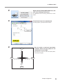
Click [File] → [New…].
Select a font which is used as a base of
a stroke character font to be created.
Click [OK].
[Select Base Font] dialog box appears.
A stroke character font is automatically created.
Click
Enter the "name of the created stroke
character. "
.
[Save] dialog box appears.
Giving a name based on the base font name allows
you to easily identify the new name at a later time.
For example, "MS P Gothic_SF" is entered.
Click [OK].
The created stroke character font is saved.
62
Chapter 4 Appendix
4-1 More Advanced Operations
Click
.
Using a stroke character font in METAZAStudio
Make sure that either of the following operations are completed in advance.
Create a stroke character font before SFEdit2 is installed.
The window shown in the figure appears when you install it. If you did not create a stroke character font
at the time of installation, reinstall SFEdit2 and create a stroke character font.
P. 18, "Installing the Driver and the Software," p. 76, "To Install Software Separately"
Create a new stroke character font.
P. 62, "Creating and saving a stroke character fonts"
1.
Change entered characters into stroke characters in a stroke character font.
Enter characters in METAZAStudio.
For the method of entering characters, see Help of METAZAStudio.
P.23, “How to Display Help for Software“
Click
.
The [Properties] dialog box appears.
If the text box containing the entered characters is not selected, you cannot select
the text box.
. Be sure to select
Chapter 4 Appendix
63
4-1 More Advanced Operations
Clikck [Format] tab.
Select [RSF].
The option of [Font] becomes Stroke character only.
Select Stroke character.
Click [OK].
Entered characters are changed into stroke characters. The stroke character font selected in
for the stroke characters.
2.
Editing Stroke character
Click .
Click the stroke character you want to edit.
Eight pointers appear around the stroke character.
Click [Edit] → [Stroke Font] → [Edit Stroke…].
SFEdit2 starts.
64
Chapter 4 Appendix
is used
4-1 More Advanced Operations
From Character List, click stroke character you want to edit.
The stroke character you want to edit is displayed in the virtual body and the stroke character becomes
editable. Change the position and shape of the stroke character.
Help for SFEdit2 (Editing Polylines)
Character List
Click
.
The edit is overwritten to the selected stroke character font.
Click
.
SFEdit2 is finished.
The edit is reflected to the stroke character.
Other operations available with METAZAStuido
What METAZAStudio offers is not just creation of 2D symbol and text data. For example, further functions like
the below are also available.
Registration of material shape
Creation and edit of desired characters and shapes
Import of image files
For information on the operation method, refer to the online help for METAZAStudio.
P.23, “How to Display Help for Software“
Chapter 4 Appendix
65
4-2 What to Do If
The [Power/Movement] button is blinking.
Do you switch on the power as the height of the head position is fixed?
As the power is switched on while the height of the head position is fixed, the initial operation is stopped. If
the machine continues the initial operation while the instrument to be imprinted is loaded, the instrument's
surface may be scratched and/or the marking pin may be damaged.
Loosen the knob counterclockwise once. Then, while pushing the head's stopper against the ring, tighten
the knob. Press the [Power/Movement] button, and the initial operation is completed and the lamp stops
blinking and lights up.
Ring
Stopper
Loosen
Tighten
Loosen
Tighten
Knob
The center of the knob
must be positioned
immediately above the
top of the triangle.
When you do not use the head cap, do you forget to adjust the height of the head position?
The tip of the head hits the surface of the instrument to be imprinted. Switch off the power by holding down
the [Power/Movement] button for one second or longer.
In the case that you perform printing without using the head cap, adjust the head position to an appropriate
position based on the surface height of the material (instrument to be imprinted) and secure the head firmly
with the knob. If the head is fixed at the position that is lower than the surface height of the instrument to be
imprinted, the tip of the head hits the surface of the instrument.
P. 35, "STEP 1: Loading the Instrument to be Imprinted"
Do you lift the head when you turn ON the power?
Since the head is lifted to the topmost, the machine considers that the surface height of the instrument to
be imprinted does not meet the requirements for carrying out printing operation. Switch off the power by
holding down the [Power/Movement] button for one second or longer.
When switching on the power, be careful not to touch the head unnecessarily.
Is a change in the height of the print surface too large?
Switch off the power by holding down the [Power/Movement] button for one second or longer.
Check the requirements for the instruments that can be imprinted and select the instrument that meets the
requirements.
P. 28, "STEP 3: Preparing Instrument to be Imprinted"
66
Chapter 4 Appendix
4-2 What to Do If
Do you set an instrument to be imprinted without using the supplied vise or the table?
Switch off the power by holding down the [Power/Movement] button for one second or longer.
If you set an instrument of which surface height is low without using the supplied table or the vise, the machine
considers that the surface height of the instrument does not meet the requirement for carrying out printing
operation. Make sure to set an instrument using the supplied vise or the table.
P. 35, "STEP 1: Loading the Instrument to be Imprinted"
Is the knob loosened?
Switch off the power by holding down the [Power/Movement] button for one second or longer.
If the knob becomes loose during printing in the case that the head cap is not used, the head position does
not match the surface height of the instrument. When you set the head position, make sure to tighten the
knob firmly.
P. 35, "STEP 1: Loading the Instrument to be Imprinted"
The machine doesn't run even when printing data is sent.
Is the power switched on?
Make sure the Power/Movement button light is on. If it is dark, press the Power/Movement button to switch
on the power.
P.27, "Switching On the Power"
Is the power cord connected correctly?
If it is not connected correctly, connect it properly.
P. 16, "Power Cord Connection"
Is the cable used for the connection to the computer connected correctly?
Check if the connection cable is disconnected.
The printed location isn't where desired
Is the instrument to be imprinted loaded at the correct location?
If striking is performed at a location other than where the instrument is loaded, then reload the instrument.
P. 35, "STEP 1: Loading the Instrument to be Imprinted"
Is the origin point of the machine displaced?
If the origin point is displaced, you cannot place printed text or image at the desired position. Using MPX-90M
Head Manager, adjust the origin point.
P. 50, "Adjustment of Origin Point"
Chapter 4 Appendix
67
4-2 What to Do If
Striking is performed, but nothing is printed.
Does the instrument to be imprinted meet the requirements for instruments that can be imprinted?
Prepare and use an instrument that can be imprinted.
P. 28, "STEP 3: Preparing Instrument to be Imprinted"
If you’re not using a head cap, does the head position match the surface height of the
instrument to be imprinted?
Check if the head position matches the surface height of the instrument in the case that you do not use the
head cap. Printing cannot be performed if the head position does not match the surface height of the instrument. Adjust the head position and then tighten the knob firmly.
P. 35, "STEP 1: Loading the Instrument to be Imprinted"
Is the marking pin bent or broken?
When nothing is printed, and changing the location where the material is loaded, the parameters for the material, or the height of the head unit does not correct the problem, then the marking pin may be bent or broken.
Try changing to an unused marking pin and carry out test printing. If you can print with the new marking pin,
it means the marking pin you had been using is bent or broken. Continue using the new marking pin.
P. 52, "Head Replacement"
Not bent or broken
Bent or broken
Bent or broken
You cannot select the material of the object to be imprinted using METAZAStudio.
Is the [Use printer driver settings] checkbox checked?
If the [Use printer driver settings] checkbox is checked in the [Select Material] dialog box, you cannot select a
material. Uncheck the [Use printer driver settings] checkbox.
Do you use a file created by an old version of METAZAStudio?
You cannot select a material using a file created by METAZAStudio of which version is earlier than 2.00. Save
the file using METAZAStudio of which version is 2.00 or later, and select a material.
You can check the version of your METAZAStudio on the window displayed by clicking the [Help] menu →
[Version] in METAZAStudio.
68
Chapter 4 Appendix
4-2 What to Do If
The printed image is unattractive.
Are the settings for the material correct?
Choose the material of the loaded instrument in METAZAStudio.
Even if the composition of the material is the same, the hardness of the printed surface may vary greatly
depending on the casting method, the composition of impurities, the presence of plating, and so on. In such
cases, fine adjustment of the striking force is necessary.
P. 59, "Registering a Composition and Adjusting the Striking Force"
Is the image printed blurry?
If the image is not printed clearly, adjust the brightness of the image.
Make a print while increasing the value of [Gamma] or [Brightness] in the preview window a little at a time. At
this time, leave the instrument to be imprinted loaded and perform overstriking at the same location. While
changing settings, continue to print until you obtain the condition you want.
METAZAStudio online help>“Commands” >[File] menu> Print Preview
Are grayscale tones printed clearly?
When grayscale tones are indistinct, go to the setting window for the METAZA driver ([Details] at the [Image
Correction] tab) and adjust the force of striking. Perform printing while leaving the value for [Impact--MAX]
unchanged and increasing the value for [Impact--MIN] a little at a time. At this time, leave the instrument to be
imprinted loaded and perform overstriking at the same location. While changing the settings in the METAZA
driver's setting window, continue to print until you obtain the darkness you want.
P. 59, "Registering a Composition and Adjusting the Striking Force"
About printing results caused by overstriking and final setting values
Overstriking is a method where you can obtain desired printing results by repeatedly striking the
same location while changing the setting a little at a time. Therefore, although you print on a new
material only once using the final setting value applied when performing overstrike, you cannot
obtain the same printing result as the one you obtain when performing overstrike.
Is the marking pin worn?
Attractive printing may be impossible if the marking pin becomes worn. Adjust the pin or change it to a new
one.
P. 52, "Head Replacement"
The image is uneven.
Is the printed surface slightly uneven?/Is the printed surface at an angle?
Attach a head cap and perform printing. If you’re using material that can be damaged by printing with the
head cap attached, replace it with an instrument that has a level printing surface.
P. 36, "Precautions for use of head cap"
Chapter 4 Appendix
69
4-2 What to Do If
Is the image darkness uneven?
Performing overstriking may improve the image quality. With the instrument left loaded, try performing
overstriking with different settings for [Gamma], [Brightness], or [Contrast] in the preview window.
METAZAStudio online help>“Commands” >[File] menu>Print Preview
Was bidirectional printing performed?
Bidirectional printing can shorten the printing time, but the image quality may suffer. If this happens, go to
the driver's setting window and clear the selection for [Bidirection], then redo printing.
METAZA Driver online help ([Material] tab)
Is the marking pin worn?
Attractive printing may be impossible if the marking pin becomes worn. Adjust the pin or change it to a new
one.
P. 52, "Head Replacement"
The image is always faint at the same location.
Is the height displacement for the printed surface excessive?
If the image is always faint at the same location even though you’re performing printing using a head cap, the
height displacement for the printed surface may be excessive. Recheck the requirements for the instruments
that can be imprinted by the machine and select the instrument that meets the requirements. Also, image
quality is not assured when printing photographic data on a curved surface with this machine.
P. 28, "STEP 3: Preparing Instrument to be Imprinted"
The machine may tilt slightly.
If the image is often faint at the same location, such as near the front right area of the table, the machine may
tilt slightly. Adjusting the levelness of the machine may improve the image quality. Please note that this is
not effective when unevenness in the image is unrelated to the printing location, such as when uneven areas
vary from an instrument to be imprinted or image to another. We recommend using a head cap whenever
such use is possible.
Procedure
Load a piece of included test-use printing material on the table.
Using the adhesive sheet, set it at the center of the table. If the included material has been used up, then
prepare a piece of material that is larger than 60 mm (2.3 in.) and has a smoothness of 0.05 mm (0.002
in.) or less. Make a print without using the head cap.
P. 35, "STEP 1: Loading the Instrument to be Imprinted"
70
Click [Devices and Printers] (or [Printers and Faxes]) from the Start menu (
Chapter 4 Appendix
).
4-2 What to Do If
Right-click the "Roland MPX-90M" icon, and
then click Printing Preferences.
The METAZA driver's Printing Preferences screen
opens.
Click [Test Print] in the [Option] tab.
The test pattern is printed on the material.
Use the scale to read and note down
locations where the test pattern is not
continuous or not visible.
Back
Note down the values in all four directions (front,
back, left, and right).
Left
Right
Front
Chapter 4 Appendix
71
4-2 What to Do If
Select [Correct slope]
Enter the scale values you noted in
into the driver.
Click [OK].
To install METAZA driver separately
You can install the driver and software at a time. For the method of installing them at a time, see P.
18, "Installing the Driver and the Software”.
Procedure
Log on to Windows as an administrator or as a member of the Administrators group.
Insert the Roland Software Package CD-ROM into the computer.
(Windows Vista/7 only: When the automatic playback window appears, click [Run
menu.exe].)
The setup menu appears automatically.
Uninstall the METAZA driver if it has been already installed.
P. 78, "Uninstalling the METAZA driver"
Go to Step if the iModela driver is not installed or it is uninstalled.
72
Click ”Custom Install."
Chapter 4 Appendix
4-2 What to Do If
Click [Install] of "METAZA Driver".
Select [Install], select [Roland MPX-90M] as
the model name, select [USB] as the port,
and then click [Start]."
Driver installation starts. Follow the on-screen instructions and continue with the installation.
Windows Vista or 7
If the screen shown here is displayed, click [Install
this driver software anyway].
Windows XP
If the screen shown here is displayed, click [Continue
Anyway].
Chapter 4 Appendix
73
4-2 What to Do If
When the screen shown here is displayed,
click [finish].
Click
of the setup menu.
Remove the CD-ROM from the CD-ROM drive.
Connect the machine and the computer with a USB cable.
Please use the included USB cable. Do not use a USB hub.
Windows Vista or 7
The driver will be installed automatically.
Windows XP
Select [No, not this time] and click [Next].
Select [Install the software automatically]
and click [Next].
74
Chapter 4 Appendix
4-2 What to Do If
Click [Finish].
If the following screen is displayed during installation
Click [Continue Anyway].
Eject and remove the CD-ROM, and then click
[Back] and repeat from the last screen.
Chapter 4 Appendix
75
4-2 What to Do If
To Install Software Separately
You can install the driver and software at a time. For the method of installing them at a time, see P.
18, "Installing the Driver and the Software”.
Procedure
Log on to Windows as an administrator or as a member of the Administrators group.
Insert the Roland Software Package CD-ROM into the computer.
(Windows Vista/7 only: When the automatic playback window appears, click [Run
menu.exe].)
The setup menu appears automatically.
Click "Custom Install."
Click [Install] of the program you want to
install.
P. 17, "The Software You Can Install and Set Up"
For detailed information about installing METAZA
driver, refer to page 72 "To install METAZA driver
separately."
Follow the messages to install the softwares.
(Windows Vista/7 only: The [User Account Control] appears, click [Allow], and install the softwares.)
76
"When installation finishes, click
of the setup menu."
Remove the CD-ROM from the CD-ROM drive.
Chapter 4 Appendix
4-2 What to Do If
The METAZA Driver Cannot Be Installed
If the driver installation stops partway through or if the wizard does not appear when you use a USB cable to
connect the PC to the machine, follow the appropriate procedure shown below.
Windows 7
1. Use a USB cable to connect the machine and the PC, and then turn the machine on.
2. If the Found New Hardware wizard appears, click [Cancel] to close it. Disconnect any USB cables for printers
other than this machine.
3. On the taskbar, click [Start], and then right-click [Computer]. Click [Properties].
4. Click [Device Manager]. When the User Account Control dialog box appears, click [Continue].
The Device Manager window appears.
5. Click [Show hidden devices] on the View menu.
6. Double-click [Printers] or [Other devices] in the list. Click the model name or [Unknown device], whichever
appears below the item you selected.
7. Click [Delete] on the Action menu.
8. In the Confirm Device Uninstall dialog box, select the "Delete the driver software for this device." Check box,
and then click [OK] to close the device manager.
9. Disconnect the USB cable that is connected to the printer, and then restart Windows.
10. Uninstall the METAZA driver.
See page 78, "Uninstalling the METAZA driver," and follow the procedure for Windows 7 from step 3 to uninstall
the METAZA driver.
11. Follow the procedure on page 72, "To install METAZA driver separately" to install the driver again.
Windows Vista
1. Use a USB cable to connect the machine and the PC, and then turn the machine on.
2. If the Found New Hardware wizard appears, click [Cancel] to close it. Disconnect any USB cables for printers
other than this machine.
3. On the taskbar, click [Start], and then right-click [Computer]. Click [Properties].
4. Click [Device Manager]. When the User Account Control dialog box appears, click [Continue].
The Device Manager window appears.
5. Click [Show hidden devices] on the View menu.
6. Double-click [Printers] or [Other devices] in the list. Click the model name or [Unknown device], whichever
appears below the item you selected.
7. Click [Delete] on the Action menu.
8. In the Confirm Device Uninstall dialog box, select the "Delete the driver software for this device." check box,
and then click [OK] to close the device manager.
9. Disconnect the USB cable that is connected to the printer, and then restart Windows.
10. Uninstall the METAZA driver.
See page 78, "Uninstalling the METAZA Driver," and follow the procedure for Windows Vista from step 3 to
uninstall the METAZA driver.
11. Follow the procedure on page 72, "To install METAZA driver separately" to install the driver again.
Windows XP
1. Use a USB cable to connect the machine and the PC, and then turn the machine on.
2. If the Found New Hardware Wizard appears, click [Finish] to close it. Disconnect any USB cables for printers
other than this machine.
Chapter 4 Appendix
77
4-2 What to Do If
3. On the taskbar, click [Start], and then right-click [My Computer]. Click [Properties].
4. Click the Hardware tab, and then click [Device Manager].
The Device Manager window appears.
5. Click [Show hidden devices] on the View menu.
6. Double-click [Printers] or [Other devices] in the list. Click the model name or [Unknown device], whichever
appears below the item you selected.
7. Click [Delete] on the Action menu.
8. In the Confirm Device Uninstall dialog box, click [OK].
9. Close the Device Manager window, and click [OK].
10. Disconnect the USB cable that is connected to the printer, and then restart Windows.
11. Uninstall the METAZA driver.
See page 79, "Uninstalling the METAZA driver," and follow the procedure for Windows XP from step 3 to uninstall the METAZA driver.
12. Follow the procedure on page 72, "To install METAZA driver separately" to install the driver again.
Uninstalling the METAZA driver
Follow the appropriate procedure below to uninstall the driver.
Windows 7
1. Turn the machine off, and disconnect the USB cable that is connecting the PC and the machine.
2. Log on to Windows as an administrator.
3. On the task bar, click [Start], [METAZA Controller], and then [Uninstall a program].
4. Select the machine's driver that you want to uninstall, and then click [Uninstall].
5. When a message prompting you to confirm that you want to uninstall the driver appears, click [Yes].
6. On the task bar, click [Start], [All Programs], [Accessories], [Run], and then [Browse].
7. Choose the name of the drive or folder where the driver is located.*
8. Select "SETUP.EXE," click [Open], and then click [OK].
9. When the User Account Control dialog box appears, click [Allow].
The driver's installer starts.
10. Click [Uninstall]. Select the machine that you want to uninstall, and then click [Start].
11. When a dialog box prompting you to restart the PC appears, click [Yes].
When the computer restarts, the uninstallation is finished.
* When you are using the CD-ROM, specify one of the following folders. (The CD drive is drive D in this example.)
D:\Drivers\WIN7X64 (64-bit version)
D:\Drivers\WIN7X86 (32-bit version)
If you're not using the CD-ROM, go to the Roland DG Corp. website (http://www.rolanddg.com/), and download
the driver for the machine you want to delete. Then, specify the folder where you extracted the downloaded
file to.
Windows Vista
1. Turn the machine off, and disconnect the USB cable that is connecting the PC and the machine.
2. Log on to Windows as an administrator.
3. On the task bar, click [Start], [Control Panel], and then [Uninstall a program].
4. Select the machine's driver that you want to uninstall, and then click [Uninstall].
5. When a message prompting you to confirm that you want to uninstall the driver appears, click [Yes].
78
Chapter 4 Appendix
4-2 What to Do If
6. On the task bar, click [Start], [All Programs], [Accessories], [Run], and then [Browse].
7. Choose the name of the drive or folder where the driver is located.*
8. Select "SETUP.EXE," click [Open], and then click [OK].
9. When the User Account Control dialog box appears, click [Allow].
The driver's setup program starts.
10. Click [Uninstall]. Select the machine that you want to uninstall, and then click [Start].
11. When a dialog box prompting you to restart the PC appears, click [Yes].
When the computer restarts, the uninstallation is finished.
* When you are using the CD-ROM, specify one of the following folders. (The CD drive is drive D in this example.)
D:\Drivers\WINVISTAX64 (64-bit version)
D:\Drivers\WINVISTAX86 (32-bit version)
If you're not using the CD-ROM, go to the Roland DG Corp. website (http://www.rolanddg.com/), and download
the driver for the machine you want to delete. Then, specify the folder where you extracted the downloaded
file to.
Windows XP
1. Turn the machine off, and disconnect the USB cable that is connecting the PC and the machine.
2. Log on to Windows as an administrator or as a member of the Administrators group.
3. On the task bar, click [Start], [Control Panel], and then [Uninstall a program].
4. Select the machine's driver that you want to uninstall, and then click [Uninstall].
5. When a message prompting you to confirm that you want to uninstall the driver appears, click [Yes].
6. On the task bar, click [Start], [All Programs], [Accessories], [Run], and then [Browse].
7. Choose the name of the drive or folder where the driver is located.*
8. Select "SETUP.EXE," click [Open], and then click [OK].
The driver's setup program starts.
9. Click [Uninstall]. Select the machine that you want to uninstall, and then click [Start].
10. When a dialog box prompting you to restart the PC appears, click [Yes].
When the computer restarts, the uninstallation is finished.
* When you are using the CD-ROM, specify one of the following folders. (The CD drive is drive D in this example.)
D:\Drivers\WINXPX64 (64-bit version)
D:\Drivers\WINXPX86 (32-bit version)
If you're not using the CD-ROM, go to the Roland DG Corp. website (http://www.rolanddg.com/), and download
the driver for the machine you want to delete. Then, specify the folder where you extracted the downloaded
file to.
Chapter 4 Appendix
79
4-3 When Moving the Machine
Attaching retainers
When moving the machine, be sure to attach the retaining materials. Moving the machine without attaching
the retaining materials may result in damage to the machine.
Procedure
Switching on the power.
P. 27, "STEP 1: Switching On the Power"
Remove the vise (or the table).
Attach the head cap.
Hold the head.
Head
Head cap
Switching off the power.
P. 45, "STEP3: Finishing Printing (Switching Off the Power)"
Hold down the Power/Movement button for
ten seconds or longer.
The head moves as shown in the figure.
Power / Movement button
80
Chapter 4 Appendix
4-3 When Moving the Machine
Fix the head at the highest position.
After loosening the knob, lift the head to the highest
position and tighten the knob.
Loosen
Tighten
The center of the
knob must be positioned immediately
above the top of
the triangle.
Head
Lift the head.
Remove the power cord and USB cable.
Attach the retaining materials.
Secure the machine at three points (with 5 screws). Attach all the retainers and wind up the screws with
the provided hexagonal wrench.
Hexagonal
wrench
Retainer
Retainer
Storage location for
retainers and screws
Rear
Close the cover and repack the machine in the original package.
When moving the machine, be sure to support it at the bottom using two hands. Attempting to move
the machine by holding it at a different location may result in damage.
Chapter 4 Appendix
81
4-4 Main Unit Specifications
Printable Area
Vise
Binder
Unprintable area
Printable area
Unprintable area
Printable area
* The 10 mm area from the binder of the vice is unprintable because the head comes into contact with the
binder.
Table
Top view of the table
Center line
Center
line
Maximum Printable Area
80 mm × 80 mm (3.1 in. × 3.1 in.)
"The setting by METAZA Driver is required.
If an image exceeds the printable area, the print
result might become uneven in the outside of the
printable area."
82
Chapter 4 Appendix
Printable Area
50 mm × 50 mm
(2 in. × 2 in.)
4-4 Main Unit Specifications
Location of Power Rating and Serial Number Label
Rear
Serial number
This is required when you seek maintenance
or support. Never remove the label.
Power rating
Use an electrical outlet that meets the
requirements for voltage, frequency, and
amperage given here.
AC adapter
Power rating
Use an electrical outlet that meets the
requirements for voltage, frequency, and
amperage given here.
Chapter 4 Appendix
83
4-4 Main Unit Specifications
Specifications
MPX-90M
Printable material
Gold, silver, copper, platinum, brass, aluminium, iron, stainless steel, etc.
(Vickers hardness [HV] of the printing surface must be 200 or less.)
Loadable material size
Maximum 100 mm (width) x 200 mm (length) x 40 mm (thickness), or 200 mm (width) x 100 mm (length) x 40 mm (thickness)
(3.9 in. x 7.9 in. x 1.5 in.), or (7.9 in. x 3.9 in. x 1.5 in.)
(The maximum of the thickness is "20 mm (0.8 in.)" at the time of
vice-use.)
Printing area
80 mm x 80 mm (3.1 in. x 3.1 in.)
Resolution
529 dpi (High resolution), 353 dpi (Photo), 265 dpi (Text), 1058 dpi
(Vector)
Printing direction
Unidirectional printing or bidirectional printing (Selectable with Windows driver)
Printing speed (Default)
50 mm/sec (1.9 in./sec) (Photo), 33 mm/sec (1.2 in./sec) (High resolution/
Text), 24 mm/sec (0.94 in./sec) (Vector)
Interface
USB interface (compliant with Universal Serial Bus Specification Revision 1.1)
Power requirements
Dedicated AC adapter
AC 100 V to 240V ± 10 % 50 / 60 Hz
Machine
DC 19 V 1.6 A
Power consumption
Approx. 24W
Acoustic noise level
Under 70 dB (A)
Operation temperature
10 to 30°C (50 to 86°F)
Operation humidity
35 to 80% (no condensation)
External dimensions
286 mm (W) x 383 mm (D) x 308 mm (H) (11.3 in. (W) x 15.1 in. (D) x
12.2 in. (H))
Weight
11 kg (24.2 lb.)
Accessories
AC adapter, power cord, test-use printing material, vise, USB cable, Roland
Software Pacakge CD-ROM, user's manual, etc.
System Requirements for USB Connection
84
Computer
A model preinstalled with the 32- or 64-bit edition of Windows XP, Windows Vista,
or Windows 7, or a model upgraded from the one preinstalled with Windows XP or
any later operation system than Windows XP
USB cable
Use the included USB cable.
Chapter 4 Appendix
85
86
87
88
R2-120113