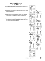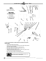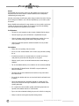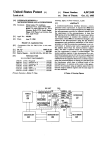
1
hydraulic
excavators
XL 2200 Excavator
Owner/Operator Manual
Covering Operation & Periodic Maintenance
Form No. 29703, Issued 2/98, Revised 0/99
IMPORTANT
Read and understand this Manual & the GRADALL and EMI Hydraulic Excavator Safety Manuals
before starting, operating or performing maintenance on this machine.
KEEP THESE MANUALS IN THE CAB
AVERTISSEMENT!
Si vous ne lisez pas l’Anglais, demandez a votre surveillant de vous donner les instructions de securite!
ATENCION
Si no lee Ingles, preguntele a su supervisor para las instrucciones de seguridad!
VORSICHT!
Wen Sie kein Enlisch lesen, bitten Sie ihren Vorgesetzten um die Sicherheitsvorschriften!
Revisions
• This page is provided so you may determine that this Manual is complete and current with respect to Gradall Engineering Specifications.
Page
Date
Revision
XL 2200 Excavator Owner/Operator Manual
TABLE
OF
CONTENTS
Table of Contents
Introduction
2
3
Related Manuals & Decals
Operator Qualifications
Orientation
PIN Location
Fastener and Fitting Torque
Models Covered
3
3
3
3
3
3
Safety
Nomenclature
Tools
Pinch Points
Other Basic Safety Issues
Decals Inside Cab
Decals Outside Cab
Seriel No. Plates
Operator’s Cab
4
5
6
7
8
11
13
15
16
Seat Adjustment
Heater
Air Conditioner
Defroster
Heater / Air Conditioner Fan
Fire Extinguisher
Cigarette Lighter
16
17
17
17
17
17
17
Control & Instrument Identification
Electronic Monitor
18
19
Digital Display Selector Switch & Symbols
U.S./Metric Unit Indicators
19
19
Caution Symbols & Alarm
Checks & Servies Before Starting Engine
Engine Operation
20
21
23
Starting the Cummins Engine
Cold Weather Starting Aids
23
23
Normal Engine Operation
24
Stopping the Engine
24
Warm-Up & Operational Checks
Adapter Attachment Installation
Use Your Crawler Properly
25
26
27
Crawler Controls
Speed Control
27
27
How to Operate Crawler
A Typical Gradall Digging Cycle
A Typical Digging Cycle
Lifting and Positioning A Load
28
29
30
31
Precautions
General
Positioning Machine for a Lift
Planning a Lift
31
31
32
32
Lubrication & Maintenance Chart
33
Lubrication & Maintenance Schedule
34
Recommended Lubricants & Capacities
Torque Chart
Towing
35
36
37
If You Get Stuck
37
Loading & Securing For Transport
Preservation & Storage
Excavator Hand Signals
38
39
41
2
Introduction
This Manual provides important information regarding safe operating procedures and
routine maintenance for the Gradall XL 2200 Hydraulic Excavator. Read and understand this
entire Manual, along with the appropriate Owner/Operator Manual, EMI Rough Terrain
Forklift Safety Manual, Gradall Material Handler Safety Manual and all instructional decals
and plates before starting, operating or performing mechanical adjustments and
maintenance procedures on this equipment. Keep Operator and Safety Manuals in cab.
Related Manuals & Decals
Separate publications are furnished with the excavator to provide information concerning
safety, replacement parts, maintenance procedures, theory of operation and vendor
components. All decals for your machine are available from your Gradall Distributor. He
can also furnish additional manuals for your machine.
Operator Qualifications
This excavator has been designed for operators weighing from lQ4 to 220 pounds (47 to
100 kg) and from 59 to 73 inches (150 to 185 cm) tall. Potential operators who do not fit
within these parameters should be observed while operating and driving the unit in a safe
area to determine their ability for safe, efficient operation.
Any operator must hold a valid driver’s license which requires acceptable age, vision,
hearing, manual dexterity and response. He must also be in acceptable physical and
mental condition. He should not be undergoing medical treatment or using drugs or
alcohol which would violate traffic laws. Before operating the excavator at a worksite, the
operator must familiarize himself with the machine by practicing in a safe, open area not
hazardous to persons or property.
The operator must read, understand and comply with instructions contained in the
following material furnished with the excavator:
• This OwnerlOperator Manual
• Gradall Hydraulic Excavator Safety Manual
• EMI Hydraulic Safety Manual
• All Instructional decals and plates
• Any additional information furnished regarding optional equipment
Orientation
When used to indicate direction or location, the terms “front”, “rear”, “left” and “right”
indicate the point of view of a person sitting in the operator’s seat. In relation to the
crawler, “front” and “rear” are determined by the location of the track drive sprockets,
which are at the rear.
PIN Location (Product Identification Number)
Specify PIN when ordering parts and when discussing specific applications and procedures
with your distributor. The PIN plate is located on front, center portion of upperstructure
frame.
Fastener and Fitting Torque
Torque values for mechanical fasteners and hydraulic fittings are given in Appendix A,
“Torque Chart”. They must be adhered to at all times. Loctite 242 must be used on all bolt
threads. Loctite 545 must be used on all hydraulic fittings. Whenever a hydraulic hose is
tightened, two wrenches must be used; one to tighten the hose, the other to hold it from
twisting. Hoses must lie and roll free of stress.
Models Covered
This Manual covers XL 2200 Crawler Mounted Excavators, starting Serial Number: 0221400.
3
XL 2200 Excavator Owner/Operator Manual
PIN Location
Safety
The following symbols are used to call your attention to safety notices:
DANGER
This symbol indicates an extreme hazard which would result in high
probability of death or serious injury if proper precautions are not
taken.
This symbol indicates a hazard which could result in death or
serious injury if proper precautions are not taken.
WARNING
CAUTION
This symbol indicates a hazard which could result in injury or
damage to equipment or property if proper precautions are not
taken.
Safe operation depends on reliable equipment and proper operating procedures.
Performing the adjustments and repairs described in this Manual will help to keep
your Material Handler in reliable condition. Use of the recommended operating
procedures can help you avoid accidents. Because some procedures may be new to
even the experienced technician, we recommend that this Manual be read,
understood and followed by all who service this machine.
DANGER, WARNING and CAUTION notes in this Manual will help you avoid injury
and damage to the equipment.
Any procedure not specifically recommended by GRADALL must be thoroughly
evaluated from the standpoint of safety before it is placed in practice. If you are not
sure, contact your GRADALL Distributor before operating.
Do not modify this machine without written permission from GRADALL..
4
Nomenclature
Hydraulic Reservoir
Valve
Pressure Release
Fuel Tank
Compartment
Hydraulic
Reservoir
Hydraulic
Filter
Mirror
Telescoping Boom
Main Boom
Boom Rollers
Engine Compartment
Mirror
Pump Compartment
Tilt Bearing
Tool Cylinder
Air Cleaner
Telescoping Cylinder
Tilt Transmission
Operator’s Cab
Hoist Cylinder
Swing Bearing
Engine
Track
Battary
Counterweight
Track Idler
Track Drive
Planetary
Track Roller
5
Track Drive
Sprocket
XL 2200 Excavator Owner/Operator Manual
Tools
FPO
Reshoot?
(Kit can be ordered under part number 8021-5004)
Qty.
Part No.
Part
Use to:
1
1
2
1
8504-1300
8504-1301
8504-1302
8504-1356
Grease Gun
Hose and Coupling
Grease Cartridges
Box Wrench (1-7/8”)
Grease fittings
Adapt grease gun to fittings
Provide initial supply for grease gun
1
1
1
2
1
8381-3109
8664-1304
8664-1305
8093-3117
8022-6035
Large Buttin Head Coupling
Open Gear Lubricant
Open Gear Lube Gun
Oil Sample Kit with Mailer
Spanner Tool
Install and remove attachment
Adapt grease gun to adjust tracks
Lubricate swing & tilt Gears
Apply open gear lubricant to gears
Collect and submit hydraulic oil sample
Adjust boom rollers
6
Pinch Points
Stay clear of Pinch Points. Getting caught in a pinch point can cause series injury or death!
7
Boom Holes
Bucket & Linkage
Access Covers
Counterweight & Another Object
Boom Cradle
Upperstructure & Carrier
XL 2200 Excavator Owner/Operator Manual
Other Basic Safety Issues
Always maintain 3-point contact with grab handles and steps when climbing on and
off the machine. Never Jump from the machine. Repair or replace any damaged steps
and grab handles.
3
2
Perform all “Checks & Services Before Starting The Engine” (pages ?? & ??) and all
“Warm-Up & Operational Checks” (page ??) at the beginning of your shift. Complete
all required maintenance before operating the XL 2200.
1
Make sure all DANGER, WARNING, CAUTION and Instructional Decals are in place and
legible. Clean or replace decals as required.
Owners often alter their machines. Make sure your XL 2200 fits the picture on the
cover of this Manual. If not, contact your Authorized Gradall Distributor before
operating the machine.
Keep everyone off of the machine while it is operating. Be alert for anyone who
may be working nearby.
Never carry a water can, equipment, or other workers’ tools or personal items on the
machine. Such items can cause other workers to approach the machine without your
knowledge and result in serious injury or death.
Stay clear of moving fan, belts, pulleys, meshing gears, drive shafts and other moving
parts. Do not operatethe XL 2200 without covers and guards in place.
Be particularly careful if this is not the machine you usually operate. Read the
manuals listed on page 2 and then practice operating the machine in a safe, open
area to become familiar with the controls.
Learn and follow your employer’s safety rules.
Do not operate with bystanders or other workers nearby.
Always sound the horn to warn others of unexpected machine movements—the horn
button is located on top of left joystick. An automatic travel alarm warns others of
machine travel in either direction.
8
Pressure may persist in hydraulic circuits long after the engine has been shut down.
This pressure can cause oil (or items such as pipe plugs) to “shoot out” at high speed
if pressure Is not released correctly. Refer to the XL 2200 Service Manual for proper
procedures to relieve hydraulic pressure trapped in circuits.
Always relieve pressure trapped in circuits before disconnecting,
removing or installing hydraulic components.
WARNING
Always be sure attachment is resting firmly on ground and that engine is stopped
before performing lubrication or maintenance procedures inside boom. Always
lower boom to rest and stop engine before leaving cab.
Use the boom tie-down device to secure the boom before transporting the XL 2200.
Boom Tie-Down
Check the operation of all tail and swing lights.
LOAD RADIUS
LOAD
POINT HEIGHT
Minimum Radius
10’ (3.0m) 15’ (4.6m)
Always check Lift Capacity Chart and plan lift (pages ?? and ??) to be certain lift can be
performed safely.
20’ (6.1m) Maximum
Radius
Above
Ground
Level
15’ (4.6m)
3095 @ 16’1”
2460 @ 18’7”
At Ground Level
Below
Ground
Level
(1405 @ 4.9m)
(1115 @ 5.7m)
CAUTION: All rated loads are based on the machine being stationary and level on a firm supporting surface. For safe
working loads, the user is expected to make due allowance for his particular job conditions, such as soft or uneven
ground, out of level conditions, side loads, hazardous conditions, experience of personnel, etc. The operator and
other personnel should fully acquaint themselves with the Operator's Manual furnished by the manufacturer before
operating this machine, and rules for safe operation of equipment should be adhered to at all times.
WARNING
9
Travel on grades is recommended only under the following conditions:
• Boom is fully retracted
• Tracks are properly adjusted
• Surface is firm enough to support the machine
• Surface provides adequate traction to prevent slipping
• Surface is not rough enough or steep enough to cause tipping
• Low travel speed is selected
XL 2200 Excavator Owner/Operator Manual
Operate On Roadway Only Under Following Conditions:
•
•
Adequate protection is positioned under tracks to prevent damage to road surface.
Signal persons are positioned to observe and signal the operator for safe
operation and travel and to guide traffic.
• Always be especially careful when using mirrors; distances are distorted and field
of view is limited, especially when swinging. Always use a signal person when
operating in tight quarters.
• Be certain area is clear of bystanders.
• All doors and covers are secured in fully closed position.
• Always sound horn as a warning before traveling.
• Be certain of location of buried pipelines, cables and overhead wired.
DANGER
DANGER
DANGER
Whenever rotating equipment (such as a mow er or mixer) is
installed on machine, adequate shielding must be installed to
deflect flying debris.
Never operate such equipment with other persons within range of
possible flying debris. Be certain that mower discharge is never
aimed at persons, equipment or structures.
As an additional precaution, safety glass and appropriate window
guards must be installed on machine.
Hitch Pin
Shipping Pin
Always install shipping pin and secure with hitch pin when preparing machine for
transport. Shipping pin is stored in valve compartment.
Hoist Cylinder
Travel On Off-Highway Grades Is Recommended Only Under The
Following Conditions:
WARNING
• Boom is fully retracted and parallel with tracks.
• Tracks are properly adjusted.
• Surface is firm enough to support unit.
• Surface provides adequate traction to prevent slipping.
• Surface is not rough enough or steep enough to cause tipping.
• Low travel speed is selected.
• There is no load in bucket, attached to boom, or in any other part of machine.
10
Decals Inside Cab
Located on right cab wall
P/N 8026-3009
Located on manual holder
P/N 8321-1037
Located on right cab wall
P/N 8091-3074
11
Located inside cab door
P/N 2-8360-1011
XL 2200 Excavator Owner/Operator Manual
Located on right cab wall
P/N 8026-3021
(for Gradall control configuration)
Located on right cab wall
P/N 8026-3022
(for S.A.E. control configuration)
Located on right cab wall
P/N 8026-3023
(for John Deere control configuration)
Located on fuse cover
P/N 8091-3021
12
Decals Outside Cab
Located ???????
P/N 8060-3038
Located beside pressure fill port
P/N 9114-3288
Located ?????
P/N 8060-3037
Located on fuel tank
P/N 7702-3008
Located ???????
P/N 8060-3036
Located inside valve compartment door
P/N 9108-3492
13
XL 2200 Excavator Owner/Operator Manual
Located ???????
P/N 8090-3017
Located ?????
P/N 8060-3039
Located ?????
P/N 8060-3026
Located ?????
P/N 2-8697-1197
Located ?????
P/N 8021-3070
14
Serial No. Plates
Machine P.I.N. Plate
Located on Front Upperstructure Frame
15
Engine
Located in Engine Compartment
Main Hydraulic Pump
Located in Pump Compartment
Implement Pump
Located in Pump Compartment
Swing Transmission
Located Beneath Boom Cradle
Swing Motor
Located on Swing Transmission
Track Drive Motors
Located Under Cover at Rear of Tracks
XL 2200 Excavator Owner/Operator Manual
Operator’s Cab
Perform all seat adjustments with engine stopped. Accidental
actuation of controls can cause serious accidents.
WARNING
It may become necessary to revise some adjustments to find the most comfortable
operating position. Be sure to stop engine first.
Lumbar
Adjustment
Control
Control Pod Pivot
Adjustment Control
(See Note)
Seat Back
Adjustment
Control
Height Adjustment Control
Upper Force and Aft
Adjustment Control
Weight Adjustment
Control
Lower Fore and Aft
Adjustment Control
Note!
Raise control to unlock control pod
and armrest assembly. Reposition
assembly as appropriate. Be certain
lock pin is fully engaged to hold
unit in selected position.
16
Heater
The cab is equipped with a heater located beneath the operator’s seat. Engine coolant
supplied to heater is controlled by a valve at rear of engine cylinder head and a
push/pull knob located on right arm rest. Raise knob fully for maximum heat or depress
knob fully for no heat. The three-speed heater fan must be operated to circulate heated air.
Air Conditioner (optional)
An air conditioner can be furnished as optional equipment. The air conditioner is controlled
by a toggle switch located on instrument/control console. Air conditioner will operate only
when heater/air conditioner fan switch is positioned for operation (High, Medium or Low).
Turn off engine coolant at engine for maximum cooling.
Defrosting
Window defrosting can be accomplished by aiming defroster fan to direct air toward
windows as appropriate. Defrost action can be increased by operating heater to provide
warm air. Maximum defrosting is accomplished by operating both heater and optional air
conditioner to provide warm dry air to defroster fan.
Heater/Air Conditioner Fan
The heater fan is located within heater housing and is controlled by a rotary switch located
on instrument/console. It provides three levels of air circulation for heating, defrosting and
air conditioning (high, medium or low).
Air is supplied to fan thru a vent in cab floor.
An air filter element is provided to clean outside air flowing to fan. Service element as
indicated in Lubrication and Maintenance Diagram. Operating conditions may require more
frequent element cleaning or replacement. A noticeable reduction of air flow from vents
indicated a need to service element.
WARNING
Always be certain to position boom or attachment on ground and
stop engine before opening or closing door or front windows.
Accidental actuation of controls can cause serious accidents.
In addition to heating, defrosting and optional air conditioning the cab is equipped for
varying degrees of natural ventilation.
Door and upper front window must be latched in open or closed position during operation.
•
Cab door can be latched in fully opened position. Lever to release door from
latched-open position is located near lower door hinge.
•
Main (upper) front window can be latched in partially or fully open position. Be
certain window is secured firmly in position selected (including closed) using both
latches.
•
Lower front window can be removed and stored in rack behind seat.
Fire Extinguisher
A fire extinguisher is stored on cab wall behind operator’s seat. Read and understand
instructions furnished on extinguisher regarding its care and operation as well as the type
of fires on which it may be used. Check often to be sure extinguisher is fully charged.
Cigarette Lighter
A cigarette lighter is provided on rear overhead panel. With lighter element removed, the
receptacle can be used to power an auxiliary 12 VDC device equipped with an appropriate
adapter.
17
XL 2200 Excavator Owner/Operator Manual
Control and Instrument Identification
WARNING
Test your controls before operating. The control pattern illustrated is
the standard Gradall control pattern. If your machine controls have
been modified to any other pattern, be certain you are familiar with
their functions before operating and ensure that control diagram in
cab is changed to show the actual pattern.
Standard Gradall control pattern is shown here.
18
Electronic Monitor
Fuel Level
Engine Coolant
Temperature
Engine Coolant
Level
Engine Oil
Pressure
Battery Charge
Hydraulic Oil
Temperature
Hydraulic Oil
Level
Hydraulic Oil
Suction Filter
Fuel Level Low
Digital Display
Window
Battery Charge
Engine Speed
Digital Display
Selector Switch
Engine Oil
Pressure
Engine Coolant
Temperature
Hydraulic Oil
Temperature
U.S. Metric Unit
Indicators
Ditigal Display Selector Switch & Symbols
This iswitch permits operator to choose which operating value will be shown in digital
display window: battery charge, engine speed, engine oil pressure, engine coolant
temperature or hydraulic oil temperature.
Appropriate symbol will glow (green) to indicate which value has been selected.
If value displayed flashes on and off, value is outside normal operating range.
U.S./Metric Unit Indicators
The operator may choose to have engine oil pressure, engine coolant temperature and
hydraulic oil temperature shown in U.S. or Metric units as defined beside symbols.
Selection of units to be shown is made by a switch (not shown) located on bottom surface
of monitor. Move switch as appropriate for U.S. units or for metric units.
U.S. or Metric mode must be selected with ignition switch in OFF position. Indicator light will
glow (green) to show which mode has been selected.
19
XL 2200 Excavator Owner/Operator Manual
Caution Symbols & Alarm
Battery Charge
Symbol glows (red) in response to low battery charge (below 11.6 VDC).
Engine Coolant Level
Symbol glows (red) and alarm sounds if coolant level falls below acceptable operating
level.
Engine Coolant Temperature
Symbol glows (red) if coolant temperature exceeds 214°F. (101°C.). Alarm sounds if
temperature reaches 220°F. ( 104°C.).
Engine Oil Pressure
Symbol glows (red) if oil pressure falls below 10 psi (.7 Kg/cm2). Alarm sounds if pressure
remains below 10 psi (.7 Kg/cm2) for 10 seconds or longer.
Fuel Level
These five lights glow (green) to indicate approximate fuel level. For example, if all five are
glowing, tank is full; if only the bottom three are glowing tank is approximately half full.
With no lights glowing, tank is less than 10% full.
Fuel Level Low
Symbol glows (red) if fuel level falls below 15% full.
Hydraulic Oil Level
Symbol glows (red) and alarm sounds if oil level falls below acceptable operating level.
Hydraulic Oil Return Filter
Symbol glows (yellow) in response to excessive resistance to flow. Cold oil can cause
symbol to glow. Refer to Warm-Up & Operational Checks (page 26) for details.
Hydraulic Oil Suction Filter
Symbol glows (yellow) and alarm sounds in response to a few conditions. Refer to WarmUp & Operational Checks (page 26) for details.
Hydraulic Oil Temperature
Symbol glows (yellow) in response to excessive hydraulic temperature (1 80°F./82 °C.).
Check fuel level symbols on electronic monitor and replenish as necessary. It is
recommended that the unit be refueled at the end of the work shift to minimize
condensation.
Check engine coolant level symbol on electronic monitor and replenish as necessary. Be
sure anti-freeze solution is adequate for expected temperatures. Be sure radiator and cooler
fins are clean.
20
Checks & Services Before Starting Engine
(To be performed at beginning of each work shift.)
Complete all required maintenance before operating unit.
Use extreme caution when checking items beyond your normal
reach. Use an approved safety ladder.
WARNING
Before removing filter caps or fill plugs, wipe all dirt and greadse away from the ports. If
dirt is allowed to enter these ports, it can shorten the life of o-rings, seals, packing and
bearings.
When adding fluids or lubricants, refer to lubricattion section of this manual to determine
proper type, specification and grade to be used.
If spark arrestors are required, be sure they are in place and in good working order.
Inspect unit for obvious damage, vandalism and needed maintenance. Check
for signs of fuel, lubricant, coolant abd hydraulic leaks. Open all access doors
and look for loose fittings, clamps, components and attaching hardware.
Replace hydraulic lines that are cracked, brittle, cut or show signs of abrasion.
Check to be sure windows and mirrors are clean and undamaged. Also be certain
mirrors are properly adjusted for operator’s position.
Check hydraulic fluid level in reservoir with boom extended half way and bottom
of bucket flat on ground. Refill reservoir as necessary using proper fluid.
21
XL 2200 Excavator Owner/Operator Manual
Service the unit in accordance with the lubrication and maintenance diagram and schedule.
Check for the presence of a fully charge fire extinguisher on wall behind operator’s seat.
Replace as necessary. Read and understand instructions regarding use and application (on
extinguisher).
WARNING
Always stop engine when refueling. Be sure area is free of open
flame, sparks or any condition which could cause fuel or fuel vapor
to ignite.
Check fuel level symbol on electronic monitor and replenish as necessary. It is
recommended that the unit be refueled at the end of work shift to minimize condensation.
WARNING
If it becomes necessary to replenish coolant in a hot radiator, stop
engine and relieve pressure before removing the radiator cap.
Relieve pressure by holding cap with heavy rags and turning cap
slowly counterclockwise until sound of escaping pressure is heard.
Wait a few minutes until sound of escaping pressure stops. Then
remove cap cautiously.
Check engine coolant level symbol on electronic monitor and replenish as necessary. Be
sure anti-freeze solution is adequate for expected temperatures. Be sure radiator and oil
cooler fins are clean. Oil cooler is hinged to facilitate cleaning.
22
Engine Operation
Turning ignition switch to START position while engine fIywheel is
rotatlng can cause serious damage to engine and/or starting motor.
WARNING
Starting the Cummins Engine
1. Insert ignition key and turn clockwise to RUN position while observing electronic
monitor.
Note!
If engine is being started at
beginning of work shift be sure to
perform all “CHECKS AND SERVICES
BEFORE STARTING ENGINE” (PAGES
22 AND 23).
All monitor symbols should glow briefly as a bulb check. Following bulb check,
symbols for battery charge, engine oil pressure, fuel level and hydraulic oil suction
filter should continue to glow and alarm should sound.
If any other symbols continue to glow, correct cause before starting engine.
2. At temperatures above 32° F. (o° C.) throttle should be at low idle. At temperatures
below 32° F. (0° C.) apply full throttle when cranking.
3. Sound horn as a warning before starting engine.
4. Turn ignition switch key clockwise to START position to engage starter motor.
Release key immediately when engine starts. If engine fails to start within 30
seconds, release key and allow starter motor to cool before trying again.
5.
After engine starts, reduce speed to low idle and observe engine oil pressure
caution symbol on electronic monitor. Symbol should go out to indicate proper
engine oil pressure. If symbol continues to glow for more than fifteen seconds, stop
engine and determine cause. Correct cause of malfunction before restarting engine.
6. Observe battery charge caution symbol. Symbol should go out to indicate that
charging system is functioning properly.
7. Observe hydraulic oil suction filter caution symbol. Symbol may go out in a few
seconds to indicate hydraulic reservoir is pressurized and oil is flowing thru suction
filter properly. Cold hydraulic oil may cause suction filter symbol to continue to
glow and alarm to sound. Continue to step 8.
8.
Adjust engine speed to approximately 1500 RPM and perform warm up and
operational checks in next section of manual.
Cold Weather Starting Aids
Diesel engine ignition is accomplished by heat generated when fuel/air mixture is
compressed within the cylinders. Because this heat may be insufficient to start a cold
engine in cold weather, the use of starting aids has become common practice.
Because of the wide variety of starting aids available it would be impractical to attempt to
provide specific instructions for their use in this manual. Carefully follow instructions
furnished with your starting aid.
If you use a starting aid employing either or a similar substance pay particular
attention to manufacturer’s warnings...
23
XL 2200 Excavator Owner/Operator Manual
Normal Engine Operation
Always operate with engine at full throttle to prevent possibility of
stalling under heavy load.
WARNING
Observe electronic monitor Irequently to be sure all engine systems are functioning properly.
Engine Oil Pressure (minimum):
Cummins - 10 to 30 psi (69 to 207 kPa)
Engine Operating Temperature:
Cummins - 160 to 200°F.(71 to 93°C)
Battery charge indication of alternator output:
Approximately 14 volts with engine running at 2000 RPM.
Be alert 10r unusual noises or vibratlon. When an unusual condition is noticed, stop
machine in a safe position and shut off engine. Determine cause and correct problem
before continuing.
Avold prolonged Idling. Idling causes engine temperature to drop and this permits
formation of heavy carbon deposits and dilution’of lubricating oil by incompletely burned
fuel. If the engine is not being used, turn it off.
Always keep engine covers closed while engine is running.
CAUTION
Stopping the Engine
Operate engine at idle speed for 3 to 5 rninutes before turning it off. This allows engine
coolant and lubricating oil to carry excessive heat away from critical engine areas. This is
especially important for turbocharged engines.
Do not “gun” engine before shut down; this practice
causes raw filel to remove oil film from cylinder walls and dilute lubncant in crankcase.
To stop engine, turn igniaon key to “OFF” position. Always remove key from switch before
leaving cab. Never leave cab with engine running.
24
Warm Up & Operational Checks
To be performed at beginning of each work shift
Complete all required maintenance before operating unit.
The safety, efficiency and service life of your excavator will be increased by performing the
following operational checks while the engine and hydraulic oil are warming to operating
temperature.
1.
Observe electronic monitor digital display for appropriate values while switching to
each position. Leave switch positioned for hydraulic oil temperature display.
2. Observe hydraulic oil suction filter caution symbol. If symbol continues to glow after
two minutes of engine operation, perform the following procedure:
a. Increase engine speed to approximately half throttle.
Note!
b. Slowly raise and extend boom fully.
c. Retract and lower boom fully and return engine speed to low idle. These boom
movements should have created sufficient positive pressure in reservoir to cause
suction filter light to go out.
3. Observe hydraulic oil return filter caution symbol. If symbol is still glowing, observe
hydraulic oil temperature value on digital display. Normally, symbol light will go
out when hydraulic oil reaches approximately 60° F. (15.6° C.).
However, if this symbol flashes on and off during operation of these circuits, it can be
assumed that return filter element is clogged and must be replaced.
4. Check operation of all excavator functions in both directions.
5.
Check operation of travel functions in both directions and be certain that travel
alarm sounds when traveling.
6. Stop engine and service all items which could not be serviced with machine in
original position.
WARNING
25
When excavator/crawler functions are not being used, reduce
engine speed to low idle. When excavator functions are idle, there
is little cooling flow thru main hydraulic pump and excessiYe heat
can damage pump.
Step 3 requires that hydraulic oil
be at least 60° F (15.6° C.). If
necessary, increase engine speed to
full throttle and stall boom extend
function to speed warming of
hydraulic system.
Note!
There is very light flow from main
hydraulic pump until there is
demand from circuits
served by the pump (all boom
functions and travel). With
hydraulic oil temperature within
operating range. and these
functions at rest, it is unlikely that
return filter indicator light will glow
even if the filter is clogged.
XL 2200 Excavator Owner/Operator Manual
Adapter Attachment Installation
WARNING
CAUTION
1.
Keep boom in fully extended position while installing bucket. Stay
clear until bucket adapter has been fitted to bucket as shown in
step 2.
Digging with a loose or improperly fitted bucket can cause
excessive wear, shear adapter can cause bolts or cause loss of
bucket.
Be sure wedge bolts are secured in storage position (toward rear) and
position bucket adapter above bucket bar as shown.
RESHOOT
2. Lower boom until concave section of
adapter contacts bucket bar.
RESHOOT
3. Move adapter toward “bucket close” position until outer end of adapter
contacts bucket. Ensure proper alignment and continue to close until
adapter contacts stops.
4. Move wedge bolts forward and
position wedge between adapter
and bucket bar. Be certain wedge
surfaces are flush between
adapter and bar and tighten
fully. Jog tool control a few times
and re-tighten. Check ofter to be
sure bolts remain tight.
5.
Position bucket linkage as desired.
RESHOOT
RESHOOT
RESHOOT
26
Use Your Crawler Properly
1.
Travel in forward direction whenever possible (with track drive motors at rear).
Traveling in reverse increases wear on sprockets and rollers.
2. Plan your work to equalize left and right turns. Constantly turning in one direction
will cause track components to wear unevenly.
Hitch Pins
3. Apply power to both tracks when turning. When power is applied to only one track
it becomes necessary for the driving track to overcome the drag of the other track.
4. Hard digging in one spot can cause as much track wear as frequent moves. Do
not neglect service to tracks and sprockets because of infrequent moves.
Shipping
Pin
5. Rough operation and operation on uneven ground can cause unnecessary wear
and damage to track components. Reasonable operation and regular maintenance
will extend track life significantly.
6. Mud, frozen mud and debris can prevent rollers from turning and cause flat spots.
Clean track components as often as necessary.
7.
Never park crawler units on a steep incline or on the side of a hill. This can distort
roller seals and cause a loss of lubricant which could ruin the rollers.
8.
Always install shipping pin and secure with hitch pins when preparing machine for
transport. Shipping pin is stored on rear wall of valve compar~nent. Do not tie
down front of boom.
Boom Hoist
Cylinder
Left Track Forward
Crawler Controls
Track Drive Pedals/Levers: Track drive pedals/levers permit independent control of
each track and its brake. Brake is released when pedal or lever is actuated and
applied when pedal or lever is released. Use of controls is illustrated on next
page.
Left Track Reverse
Right Track Reverse
Engage Pedal/Lever as indicated for desired functions
Speed Control
Your crawler is equipped with a toggle switch to select crawler speed range.
High Speed: Move toggle to right.
Low Speed: Move toggle to left for maximum tractive effort and maneuverability
in tight quarters.
Speed changes can be made while traveling or when stopped.
27
Right Track Forward
XL 2200 Excavator Owner/Operator Manual
How to Operate the Crawler
Practice with travel controls in a safe, open area.
Front of
Crawler
Front of
Crawler
Front of
Crawler
Straight
Forward
Turn Left
Turn Right
A C
C
Front of
Crawler
A
A
C
B C
A D
B
CounterRotate
Left
Front of
Crawler
Front of
Crawler
D
B
D
B D
Front of
Crawler
CounterRotate
Right
Front of
Crawler
Reverse
Right
Turn
Reverse
Left Turn
Straight
Backward
WARNING
Avoid confusion! Before actuating track drive pedals, think about
the direction you are facing with respect to the direction the
crawler is facing. (Drive sprockets are at rear of c r a w l e r ) .
Confusion could cause you to travel in the direction opposite that
expected.
28
A Typical Gradall Digging Cycle
1.
Position unit for efficient digging cycle and check for appropriate clearances.
Avoid accidental actuation of controls. Always stop engine before
repositioning door and windows for ventilation.
WARNING
2. Stop engine and secure door and windows in desired position for ventilation.
Remove shipping pin from boom and store in valve compartment.
3. Warm up engine and hydraulic oil and then move throttle to full throttle position.
WARNING
Test your controls before operating. The control pattern shown is
the standard Gradall pattern. If controls have been modified to
another pattern, be sure you are familiar with functions and ensure
that diagram in cab shows actual pattern.
4. Be certain left armrest is locked in down position to energize joysticks and pedals.
Practice with controls in a safe. open area.
WARNING
When excavator/crawler functions are not being used, reduce
engine speed to low idle. When excavator functions are idle, there
is little cooling flow thru main hydraulic pump and excessive heat
can damage pump.
Always operate with engine running at full throttle to prevent stalling under heavy load.
Lower Boom
Extend Boom
Close Bucket
*Full Speed Tilt
Boom Tilt
CLockwise
Swing Left
Swing Right
Open Bucket
Aux. Attachment
(Press to Engage)
*Boom Tilt
Counterclockwise
Horn
Raise Boom
Retract Boom
*If tilt speed has been reduced for conditions (see page 20) speed can be temporarily
increased to maximum by depressing FULL SPEED TILT button.
Joysticks & Pedals Return to Neutral
Position When Released.
29
XL 2200 Excavator Owner/Operator Manual
A Typical Digging Cycle
1.
Pull back on the left joystick (A) to raise the boom from the boom rest. Be sure to
raise the boom far enough to clear all obstructions.
1
2. Move the right joystick to the left (G) to swing left or to the right (H) to swing the
boom end to digging the site.
3. While pushing the right joystick forward (F) to extend the boom, push the left
joystick forward (B) to lower the boom to position for the start of the cut.
2
3
4. Move the left joystick to the left (C) to open the bucket or to the right (D) to close
the bucket for correct penetration. Teeth should angle downward slightly (about
(5°). The angle may be greater for soft digging.
4
5
6
7
8
9
10
11
30
Lifting and Positioning A Load
Precautions
• Do not depend on machine tipping as a warning ot overload. Some load ratings
are based on hydraulic lift capacity, not stability.
•
Hydraulic relief valve settings must be correct when lifting and positioning loads.
•
Suspend loads only as shown. Passing load line over open bucket can cause
uncontrolled movement of load. Boom must be tilted to level position.
•
Always operate at full engine RPM when handling a heavy load. This prevents
stalling under load.
•
Keep everyone clear of machine (especially the boom and suspended load). Use
guide ropes to position load.
•
Do not travel with a suspended load. Excavators are not designed for pick and
carry lifts.
•
Sudden swing braking can cause unexpected movemen1 of the load and tip the
machine.
•
Be sure tracks are properly adjusted before traveling with a load.
•
Keep load line vertical. Side loads can cause structural damage and tip the
machine.
•
Use appropriate lift capacity chart if uni1 has a boom extension attached.
•
Be thoroughly familiar with excavator hand signals (shown at end of manual).
General
The excavator can lift and position loads safely only if you plan the lift properly.
Failure to plan a lift properly can cause death or serious injury.
DANGER
There is a great lift capacity difference between the excavator’s best and worst lift positions.
Just because it can lift a load from one point does not mean it can safely deliver the load
to any other point.
For example, the second best liflcing position is with the excavator level, the boom level
and fully retracted.
Assume that you have just lifted the rated load (7035 pounds) from a truck with the unit
in this position. You may raise the boom 2 feet, 3 inches to the very best lifting position.
Also, since all loads shown on the chart are based on hydraulic limits (not stability limits)
you may safely swing to any position. However~ load limits begin to be exceeded if you
lower the boom below horizontal or above 10 foot LOAD POINT HEIGHT. Study “LOAD
POINT HEIGHT” and “MIN. RADIUS” columns on Rated Lift Capacity Chart while reading this
paragraph again. Also note how the load capacities decrease for other conditions (other
columns).
The point is, you must plan the lift based on the worst condition of the lift and delivery,
not the best. The worst condition can only be determined by performing an UNLOADED
TEST LIFT AND DELIVERY of the load.
The “common sense” and “feel” an experienced operator might apply in regard to “tipping
loads” DOES NOT APPLY to loads limited by hydraulic lift capacity. All loads shown on
chart in cab are hydraulic lifit capacities. Exceeding these capacities can cause a relief
valve to open allowing the load to fall, or in some cases, the machine to tip over.
31
XL 2200 Excavator Owner/Operator Manual
Positioning Machine for A Lift
Before discussing the steps in planning a lift, let’s consider the most favorable excavator
positions for making a lift.
Whenever possible, the machine should be on a firm, level surface when making a lift.
Also, avoid traveling with a load if possible.
The shorter the load radius, the greater the lift capacity. Position the unit to minimize boom
extension and swing while keeping a safe distance from obstructions and excavations.
Finally, position machine to gain maximum visibility of load and delivery point. If
conditions do not permit a clear view, use a signal man.
Planning A Lift
1. Determine the weight of the load. Weight of slings, chains and auxiliary liftng
devices must be added as part of the load. Refer to lift capacity chart for weight
adjustment required for bucket.
Note!
Lift capacities are based on machine
being on a firrn, level surface and
also on load being freely
suspended beneath bucket adapter.
2. Move the machine to the best probable position for making the lift.
3. Perform an unloaded trial run of litt to determine maximum boom
height/depth and load radius required to complete lift.
4. Measure boom height/depth from hole in adapter to ground level
(same level as bottom of tracks). Be sure to allow for length of
chain and height of load.
5. Measure load radius from inner corner of frame at front of cab to
vertical load line and add distance to center of rota io
(69 inches).
6.
Refer to lift capacity chart column for required load radius. If
required radius is between columns, use column for next larger
radius.
7.
Check the appropriate capacities for required boom heightldepth. The smaller of
these capacities is the maximum is the maximum load permitted for lift conditions.
8.
To determine practical working load limits the operator must also consider wind,
hazardous conditions, experience of personnel and proper load handling.
WARNING
Measure
89 Inches
The automatic boom tilt brake will not prevent boom from tilting
in response to an external load. Load must be centered under
bucket adapter with boom level from side to side.
To lift loads, remove bucket, level boom from side to side and close adapter fully against
stops. Pass chain thru adapter as shown and be certain chain is locked on itself. A chain
can be used for light loads with bucket installed and adapter closed against stops.
Never pass load line over open bucket. Relief valves in bucket circuit could cause
unexpected dangerous movement of the load. Bucket linkage could also be damaged.
32
Lubrication & Maintenance Chart
5
3
Symbols
• = Lube Fitting
= Other Service
= Service Both Sides
6
7 8
9 11 12 13 14
15
4
2
1
Lubricant Symbols
AF - Anti-Freeze (permanent)
CG - Grease (extreme presure)
DF - Diesel Fuel
EO - Engine Oil
GL - Open Gear Lubricant
GO - Multi-purpose Lube
HF - Hydraulic Fluid
16
28
31
25
23
18
17
32
33
34
19
37
36
35
38
20 21
22
26
27
25
24
25
29
30
See Warning
Below
51
49
46
47
48
See vendor component literature for additional lubrication and maintenance information.
Lubrication Notes
• Clean lubrication fittings before lubricating.
• Intervals shown are for normal (8 hour day) usage and conditions. Adjust intervals
for abnormal usage and conditions.
• Service items indicated by dotted leaders on both sides of unit.
• Drain engine and gear cases only after operation when oil is hot.
• Check lubricant levels when lubricant is cool.
• Clean filter and air cleaner housing and reusable elements using solvent or diesel
fuel. Dry components thoroughly using lint free cloth.
• Apply a light coating of engine oil to all linkage pivot points.
Serious injury can result of proper adjustment procedure is not
followed. See instructions on warning plate.
WARNING
33
XL 2200 Excavator Owner/Operator Manual
50
CAUTION
Item
Service intervals are based on machine usage of 1500 hours
annually. Use of your unit may vary significantly and you must
adjust service frequency for your usage to obtain maximum service
life. Frequency headings in the following schedule indicate a
calendar limit and an operating hour limit. Always check hourmeter
and date at beginning of shift to be certain services are performed
at proper interval. Perform service at whichever interval occurs first.
Lube
Symbol
Daily or Shift (10 Hour U-maximum) Lubrication & Maintenance
1. Hoist Cylinder Barrel Pivot . . . . . . . . . . . . . . . . . . . . . . . . . . . . . . . . . . . . . . . . . . . . . . . . . . . . . . . . . . . . . . . . . . . . . . . . . . . . . . . . . . . . . . . . CG
2. Swing Bearing . . . . . . . . . . . . . . . . . . . . . . . . . . . . . . . . . . . . . . . . . . . . . . . . . . . . . . . . . . . . . . . . . . . . . . . . . . . . . . . . . . . . . . . . . . . . . . . . . CG
3. Tilt Bearing . . . . . . . . . . . . . . . . . . . . . . . . . . . . . . . . . . . . . . . . . . . . . . . . . . . . . . . . . . . . . . . . . . . . . . . . . . . . . . . . . . . . . . . . . . . . . . . . . . . CG
4. Cradle Pivot . . . . . . . . . . . . . . . . . . . . . . . . . . . . . . . . . . . . . . . . . . . . . . . . . . . . . . . . . . . . . . . . . . . . . . . . . . . . . . . . . . . . . . . . . . . . . . . . . . . CG
11. Fuel Filler Cap (fill daily at end of work shift to minimize condensation) . . . . . . . . . . . . . . . . . . . . . . . . . . . . . . . . . . . . . . . . . . . . . . . . . . . . DF
13. Hydraulic Fluid Level (check with machine level boom extended half way & bottom of bucket flat on ground - if required stop engine
& vent reservoir by un-seating vent valve stem of resenvoir breather [81- refill thru pressure fill port [12] using adapler
P/N 8364-1564 OR refill thru main return filter [15]) . . . . . . . . . . . . . . . . . . . . . . . . . . . . . . . . . . . . . . . . . . . . . . . . . . . . . . . . . . . . . . . . . . . HF
20. Tool Link Pivot (at adapter) . . . . . . . . . . . . . . . . . . . . . . . . . . . . . . . . . . . . . . . . . . . . . . . . . . . . . . . . . . . . . . . . . . . . . . . . . . . . . . . . . . . . . . CG
21. Adapter Pivot . . . . . . . . . . . . . . . . . . . . . . . . . . . . . . . . . . . . . . . . . . . . . . . . . . . . . . . . . . . . . . . . . . . . . . . . . . . . . . . . . . . . . . . . . . . . . . . . . CG
22. Tool Link Pivot (at cylinder) . . . . . . . . . . . . . . . . . . . . . . . . . . . . . . . . . . . . . . . . . . . . . . . . . . . . . . . . . . . . . . . . . . . . . . . . . . . . . . . . . . . . . . . CG
23. Tool Cylinder Rod Pivot . . . . . . . . . . . . . . . . . . . . . . . . . . . . . . . . . . . . . . . . . . . . . . . . . . . . . . . . . . . . . . . . . . . . . . . . . . . . . . . . . . . . . . . . . . CG
24. Connectirlg Link Pivot . . . . . . . . . . . . . . . . . . . . . . . . . . . . . . . . . . . . . . . . . . . . . . . . . . . . . . . . . . . . . . . . . . . . . . . . . . . . . . . . . . . . . . . . . . . CG
25. Boom Roller Pivots . . . . . . . . . . . . . . . . . . . . . . . . . . . . . . . . . . . . . . . . . . . . . . . . . . . . . . . . . . . . . . . . . . . . . . . . . . . . . . . . . . . . . . . . . . . . . CG
26. Tool Cylinder Base Pivot . . . . . . . . . . . . . . . . . . . . . . . . . . . . . . . . . . . . . . . . . . . . . . . . . . . . . . . . . . . . . . . . . . . . . . . . . . . . . . . . . . . . . . . . . CG
27. Extension Cylinder Rod Pivot . . . . . . . . . . . . . . . . . . . . . . . . . . . . . . . . . . . . . . . . . . . . . . . . . . . . . . . . . . . . . . . . . . . . . . . . . . . . . . . . . . . . . . CG
36. Air Cleaner Condition Indicator (observe with engine running at full throttle-clean or replace primary [oute] element as required replace safety [inner] element every third primary service - item 37 is air cleaner) . . . . . . . . . . . . . . . . . . . . . . . . . . . . . . . . . . . . . . . . . . . . . CG
39. Hoist Cylinder Rod Pivot . . . . . . . . . . . . . . . . . . . . . . . . . . . . . . . . . . . . . . . . . . . . . . . . . . . . . . . . . . . . . . . . . . . . . . . . . . . . . . . . . . . . . . . . . CG
43. Crankcase Dipstick (check lubricant level & refill as required - [44 is filler cap]) . . . . . . . . . . . . . . . . . . . . . . . . . . . . . . . . . . . . . . . . . . . . . . EO
Weekly (50 Hour Maximum) Lubricatlon & Maintenance (Include all previous periodic services)
7. Swing Transmission Level Cap (remove cap & fill plug [item 9] it required add lube until it runs from level cap port - Install cap & plug) GO
18. Radialor (check level & anti-freeze protection - refill as required) . . . . . . . . . . . . . . . . . . . . . . . . . . . . . . . . . . . . . . . . . . . . . . . . . . . . . . . . . AF
29. Tilt Brake Level Plug (check level & refill a required) . . . . . . . . . . . . . . . . . . . . . . . . . . . . . . . . . . . . . . . . . . . . . . . . . . . . . . . . . . . . . . . . . . . HF
30. Tilt Transmission Level Plug (check level & refill as required) . . . . . . . . . . . . . . . . . . . . . . . . . . . . . . . . . . . . . . . . . . . . . . . . . . . . . . . . . . . . . GO
35. Air Cleaner Vacuator Valve (check for damage - should be empty with engine stopped) . . . . . . . . . . . . . . . . . . . . . . . . . . . . . . . . . . . . . . . . _
33. Fue/Water Separator (drain water) . . . . . . . . . . . . . . . . . . . . . . . . . . . . . . . . . . . . . . . . . . . . . . . . . . . . . . . . . . . . . . . . . . . . . . . . . . . . . . . . . . 40. Swing Bull Gear (apply open gear lubricant) . . . . . . . . . . . . . . . . . . . . . . . . . . . . . . . . . . . . . . . . . . . . . . . . . . . . . . . . . . . . . . . . . . . . . . . . . GL
46. Track Idler (observe for leakage - repair or replace leaking idber - add SAE 30 or 40 to repaired idler) . . . . . . . . . . . . . . . . . . . . . . . . . . . EO
47. Track Rollers (observe all rollers for leakage - repair or replace leaking rollers - add SAE 30 or 40 to repaired roller) . . . . . . . . . . . . . . . . EO
51. Phnetarg Gear Level Plug (check level with plugs in position shown & refill as necessary - Item 49 is fill plug) . . . . . . . . . . . . . . . . . . . . . GO
At End of First 30 Days (250 Hours Maximum) Lubrication & Maintenance
6. Swing Transmission Drain Plug (drain & refill) . . . . . . . . . . . . . . . . . . . . . . . . . . . . . . . . . . . . . . . . . . . . . . . . . . . . . . . . . . . . . . . . . . . . . . . . GO
50. Planetary Gear Drain Plug (drain & fill to level with lugs in position shown) . . . . . . . . . . . . . . . . . . . . . . . . . . . . . . . . . . . . . . . . . . . . . . . . GO
• Check torque of all Items listed in torque table (refer to operalor’s manual) . . . . . . . . . . . . . . . . . . . . . . . . . . . . . . . . . . . . . . . . . . . . . . . . . ._
Monthly (125 Hour Maximum) Lubrication & Maintenance (include all previous periodic services)
19. Drive Belt (check condition - replace as required) . . . . . . . . . . . . . . . . . . . . . . . . . . . . . . . . . . . . . . . . . . . . . . . . . . . . . . . . . . . . . . . . . . . . . ._
28. Tilt Gear (apply open gear lubricant) . . . . . . . . . . . . . . . . . . . . . . . . . . . . . . . . . . . . . . . . . . . . . . . . . . . . . . . . . . . . . . . . . . . . . . . . . . . . . . . GL
48. Track Adjustmenl Fitting (check for proper track tension - there should be 13⁄16 in. [21 mm] sag between top of track idler & upper
support rolller - adjustment must be made only by qualified maintenance person) . . . . . . . . . . . . . . . . . . . . . . . . . . . . . . . . . . . . . . . . Every 250 Hour Lubrlcation & Maintenance (include all previous periodic services)
17. Heater Air Fliter (Inspect & clean or replace as required) . . . . . . . . . . . . . . . . . . . . . . . . . . . . . . . . . . . . . . . . . . . . . . . . . . . . . . . . . . . . . . . . . 41. Engine Oil Filter (replace element at 250 hour intervals) . . . . . . . . . . . . . . . . . . . . . . . . . . . . . . . . . . . . . . . . . . . . . . . . . . . . . . . . . . . . . . . . . 42. Crankcase Drain Plug (change oil at 250 hour intervals) . . . . . . . . . . . . . . . . . . . . . . . . . . . . . . . . . . . . . . . . . . . . . . . . . . . . . . . . . . . . . . . . EO
Every Four Months (500 Hour Maximum) Lubrication & Maintenance (include all previous periodic services)
38. Fuel/Water Separator (replace element) . . . . . . . . . . . . . . . . . . . . . . . . . . . . . . . . . . . . . . . . . . . . . . . . . . . . . . . . . . . . . . . . . . . . . . . . . . . . ._
Semi-Annual (750 Hours Maximum) Lubrication & Maintenance (include all previous periodic services)
5. Swing Transmission Breather (remove clean or replace) . . . . . . . . . . . . . . . . . . . . . . . . . . . . . . . . . . . . . . . . . . . . . . . . . . . . . . . . . . . . . . . . . ._
13. Hydraulic System (have hydraulic fluid analyzed to determine condition - use test port mini-check to obtain sample - draln
flush, replenish & bleed if required & clean suction screen [141 when system is drained - refer to service manual for procedure to bleed
system before starting or operating unit) . . . . . . . . . . . . . . . . . . . . . . . . . . . . . . . . . . . . . . . . . . . . . . . . . . . . . . . . . . . . . . . . . . . . . . . . . . . . HF
15. Hydraulic Return Filter (replace element if it has not been replaced in previous 750 hours - also clean magnet) . . . . . . . . . . . . . . . . . . . . . ._
31. Tilt Transmission Fill Port Breather (remove, clean or replace) . . . . . . . . . . . . . . . . . . . . . . . . . . . . . . . . . . . . . . . . . . . . . . . . . . . . . . . . . . . . . ._
32. Tilt Brake Breather (remove clean or replace) . . . . . . . . . . . . . . . . . . . . . . . . . . . . . . . . . . . . . . . . . . . . . . . . . . . . . . . . . . . . . . . . . . . . . . . . . ._
45. Battery (check electrolyte level & refill as required) . . . . . . . . . . . . . . . . . . . . . . . . . . . . . . . . . . . . . . . . . . . . . . . . . . . . . . . . . . . . . . . . . . . . ._
• Check torque of all items listed in torque table (refer to operator’s manual) . . . . . . . . . . . . . . . . . . . . . . . . . . . . . . . . . . . . . . . . . . . . . . . . . ._
Annual (1500 Hour Maximum Lubrication & Maintenance (include all previous periodic services)
6. Swing Transmission Drain Plug (drain & refill) . . . . . . . . . . . . . . . . . . . . . . . . . . . . . . . . . . . . . . . . . . . . . . . . . . . . . . . . . . . . . . . . . . . . . . . . GO
8. Hydraulic Resevoir Breather (replace element) . . . . . . . . . . . . . . . . . . . . . . . . . . . . . . . . . . . . . . . . . . . . . . . . . . . . . . . . . . . . . . . . . . . . . . . . ._
13. Hydraulic System (unless hydraulic fiuid is analyzed semi-annually to check level of contamination system must be drained flushed
replenished & bled annually - clean suction screen [14] when system is drained - see service manual for procedure to bleed system
before starting or operating unit) . . . . . . . . . . . . . . . . . . . . . . . . . . . . . . . . . . . . . . . . . . . . . . . . . . . . . . . . . . . . . . . . . . . . . . . . . . . . . . . . . . HF
16. Joystick Plungers (raise boot & lube rounded top of each plunger) . . . . . . . . . . . . . . . . . . . . . . . . . . . . . . . . . . . . . . . . . . . . . . . . . . . . . . . CG
18. Engine Coolng System (drain & refill cooling system based on period suggested by anti-lreeze manufacturer) . . . . . . . . . . . . . . . . . . . . . . ._
33. Tilt Brake Drain Plug (drain & refill) . . . . . . . . . . . . . . . . . . . . . . . . . . . . . . . . . . . . . . . . . . . . . . . . . . . . . . . . . . . . . . . . . . . . . . . . . . . . . . . . HF
34. Tilt Transmission Drain Plug (drain & refill) . . . . . . . . . . . . . . . . . . . . . . . . . . . . . . . . . . . . . . . . . . . . . . . . . . . . . . . . . . . . . . . . . . . . . . . . . . GO
50. Planetary Gear Drain Plug (drain & refill) . . . . . . . . . . . . . . . . . . . . . . . . . . . . . . . . . . . . . . . . . . . . . . . . . . . . . . . . . . . . . . . . . . . . . . . . . . . GO
FAILURE TO USE GRADALL HYDRAULIC FILTER ELEMENTS COULD VOID WARRANTY.
No. of
Points
1
2
2
2
1
1
2
2
2
1
2
12
1
1
1
1
1
1
1
1
1
1
2
1
2
14
2
1
2
_
1
1
2
1
1
1
2
1
1
1
1
1
1
_
1
1
1
8
1
1
1
2
34
Recommended Lubricants & Capacities
Specifications
APPLICATION
ENGLISH
LITERS
MIL-L-2105D
11.6 pints
5.5
50/50 mix
Permanent
23.3 quarts
22
EO (engine oil)
15W-40
Mil-L-2104E
11.6 quarts
11
CG (extreme pressure lube)
No. 2
_
_
_
Hydraulic System
HF (hydraulic fluid)
***
***
55 gallons
208.5
Swing Bull Gear
GL (open gear lubricant)
_
Part NO. 8664-1304
_
_
Swing Transmission
GO (multi-purpose lube)
EP 85/140
MIL-L-2105D
5 quarts
4.73
HF (hydraulic fluid)
***
***
Refill to lower level plug
Tilt Bull Gear
GL (open gear lubricant)
_
Part No. 8664-13-4
_
_
Tilt Transmission
GO (multi-purpose lube)
EP 85/140
MIL-L-2105D
1.5 pints
.71
Track Idler
EO (engine oil)
SAE 30-40
MIL-L-2104E
7.8 ounces ea.
.23
Track Rollers
EO (engine oil)
SAE 30-40
MIL-L-2104E
9.6 ounces ea.
.28
Crawler Planetary
Engine Cooling System
Engine Crankcase
Grease Fittings
Tilt Brake
SYMBOL
GRADE**
GENERAL
GO (multi-purpose lube)
EP 80/90
AF (anti-freeze/water)
Capacities*
ISO
*Capacities are approximate; check level to be sure.
**May vary; check vendor literature in service manual for ambient temperature limits.
***Hydraulic Fluid Specifications:
Pour Point -46° F.;SSU @ 100° F. 275; Flash point 442° F.
Approved Supplier & Type: Mobile Mobilfluid 424.
35
XL 2200 Excavator Owner/Operator Manual
Torque Chart
Check torque using an accurate torque wrench to apply maximum torque value shown.
DO NOT EXCEED MAXIMUM TORQUE. Exceeding maximum torque may cause fastener to fail.
APPLICATION
QUANTITY
THREAD SIZE
(GRADE)
1
Boom Roller Eccentric Keepers
24
Extension Cylinder Support
8
5⁄8
Swing Bearing
84
5⁄8
Swing Motor
2
1
Swing Transmission
8
5⁄8
Tilt Bearing
84
5⁄8
Tilt Motor
2
1
Tilt Transmission
4
5⁄8
⁄2 - 13 (8)
TORQUE (lubricated)
POUND/FEET
NEWTON/METERS
MINIMUM MAXIMUM MINIMUM MAXIMUM
100
110
136
150
- 11 (8)
200
215
272
292
- 11 (8)
200
215
272
292
⁄2 - 13 (8)
100
110
136
150
- 11 (8)
200
215
272
292
- 11 (8)
200
215
272
292
⁄2 -13 (8)
100
110
136
150
200
215
272
292
- 11 (8)
36
Towing
REFER
TO
SERVICE MANUAL FOR INSTRUCTIONS
FOR TOWING CRAWLER.
If you Get Stuck
If unit becomes stuck in soft ground you can use the boom to help free it.
Position upperstructure parallel with tracks with boom to front or rear as appropriate for boom
to help push or pull unit free. Pushing works best.
While actuating travel pedals/levers in appropriate direction extend or retract boom as
required to push or pull to solid ground.
Whether pushing or pulling, be sure to adjust boom angle as required to keep bucket
imbedded in ground.
37
XL 2200 Excavator Owner/Operator Manual
Loading & Securing For Transport
Weight with 60 inch ditching bucket is 27,000 pounds.
1. Retract horizontal boom fully, install transport lock pin and secure with hitch pin.
Pins are stored in valve compartment.
2. Align upperstructure with tracks (drive sprockets at rear.) Install two chains from
holes near rear of frame to tracks as shown.
3. Attach four legged chain as shown. Using crane of adequate capacity, take most of
slack from chains.
4. Pad chains as necessary to prevent damage to components and paint. Be certain
right rear chain is clear of hydraulic filter.
5.
Take all slack from chains and inspect rigging for safety. Use tag lines to control
load during lift.
6. Position excavator as required and secure to transport using four cross chains as
shown.
7. Do not tie down front of boom.
38
Preservation & Storage
General
Recommended short term storage practices vary with conditions at the storage site, the
length of time the unit will be stored (t vo months maximum) and t’ne temperatures
expected during the storage period.
Obviously, some storage sites will require greater storage precautions than others. Choosing
the best storage site available is one of the most important steps you can take to protect
the machine.
Because Gradall cannot anticipate all storage situations, we do not provide a step-by-step
procedure for shot term storage. However, we do require that you review the following
points and implement those appropriate to your situation:
For All Situations:
• This may be a good opportunity to take a sample of hydraulic fluid for analyses.
•
Lubricate all grease gun points until fresh lube is expelled from lube point.
•
Check the hourmeter and the Lubrication and Maintenance schedule. If you are
close to any lubricant change period, make the change before storage.
•
Check level of anti-freeze protection and drain and refill if necessary to obtain
proper protection.
Site Conditions:
• Always select a site providing a firm, level surface.
39
•
Be sure site is free of natural hazards: salt or corrosive spray, mud slides, flooding,
fire, etc.
•
If machine must remain on an unpaved surface, be sure tracks are resting on
sturdy boards to prevent tracks from being frozen in soft ground..
•
Whenever possible, select a site that will minimize the threat of theft damage or
vandalism.
•
The site should afford sufficient space to allow the unit to be exercised periodically.
•
Apply Boeshield* T9 (Gradall Part No. 1440-4645) to exposed cylinder rods.
General Considerations
•
Thoroughly clean all mud and debris from the machine to help protect surfaces
from corrosive action.
•
Be sure all doors windows and covers are closed and locked. Install vandal covers
if available.
•
Exercise all excavator functions periodically, preferably on a weekly basis. The
exercise period should last until engine and hydraulic oil have reached normal
operating temperature.
•
If it is impractical to exercise machine regularly, and if freezing temperatures are
expected, remove batteries and store in a warm location.
•
Tape a note inside cab window indicating the person to be called in an emergency.
•
Always be certain to remove ignition key before leaving machine.
XL 2200 Excavator Owner/Operator Manual
General Considerations
• Throughly clean all mud and debris from the machine to help protect surfaces from
corrosive action.
• Be sure all doors and windows and covers are closed and locked. Install vandal
covers if available.
• Exercise all excavator functions periodically, preferably on a weekly basis. The
exercise period should last until engine and hydraulic oil have reached normal
operating temperature.
• If it is impractical to exercise machine regularly, and if freezing temperatures are
expected, remove batteries and store in a warm location.
• Tape a note inside cab window indicating the person to be called in an emergency.
• Always be certain to remove ignition key before leaving machine.
40
Excavator Hand Signals
41
XL 2200 Excavator Owner/Operator Manual
42
The information contained in this
Manual is protected by copy r i g h t.
Unauthorized reproduction of this
Manual, in whole or in part, in
any form whatsoever, is strictly
prohibited. Specifications are
correct at time of publication.
Howev e r, Gradall reserves the
right to make any necessary
changes without prior not i c e .
Gradall ® is a registered trad e m a r k
for Hydraulic Exc a vators, Ma te r i a l
Handlers, Industrial Maintenance
Machines, Attac h m e n ts and ot h e r
C o m p o n e n ts m a n u fac t u r e d and
marketed by The G r ad a l l Company.
ISO
9 0 01
Certified
CALIFORNIA
Proposition 65 Warning
Diesel engine exhaust and some of
its constituents are known to the
State of California to cause cancer,
birth defects, and other reproductive
harm.
hydraulic
excavators
406 Mill Ave. SW, New Philadelphia, Ohio 44663 • (330) 339-2211 • Fax (330) 339-8468 • www.gradall.com