1
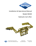
Installation & Operational Manual
Model D6120-40-27k
Dumping Gripper Arm Lifter
Protected by US Patents 6,921,239 & 7,273,340
Perkins Manufacturing Company
Creators of the TuckAway® Cart Lifter
www.perkinsmfg.com
800-882-5292
Revised:11/7/2013
Page 1 of 42
D6120-40-27k Gripper Arm Lifter Specifications
Cart Compatibility
ANSI Type B, C, D, and 55 gal. drums
Typical Mounting Application
Rearloader and Sideloader
Tipper-Bar Compatible?
No.
Flow Rate Requirement
3.5 gpm
Cycle Time
6-8 seconds (up and down)
Recommended Pressure Setting*
1,550 psi at the pressure relief valve
Maximum System Pressure
3,000 psi
Weight Capacity**
400 lbs
Dump Angle
45 degrees from the horizon
Mounting Height (ground level to top of mounting
plate)
Approximate Unit Weight (not counting
packaging)
38” up to 42”.
185 lbs
Hydraulic Package
Tap-In kits are sold separately
Warranty
2-years ***
Perkins regularly makes product improvements. Specifications are subject to change without notice.
* Actual pressure required to lift a load can vary.
** Do not lift more than the recommended amount printed on the cart by the cart manufacturer or
damage or injury may result.
*** See Warranty page enclosed in this manual for full details of coverage
Perkins Manufacturing Company
Creators of the TuckAway® Cart Lifter
www.perkinsmfg.com
800-882-5292
Revised:11/7/2013
Page 2 of 42
Overall Dimensions
Perkins regularly makes product improvements. Dimensions are subject to change without notice.
Perkins Manufacturing Company
Creators of the TuckAway® Cart Lifter
www.perkinsmfg.com
800-882-5292
Revised:11/7/2013
Page 3 of 42
Glossary of Terms
Cart Types
ANSI Type B carts
(US-Style two-bar
carts) with a
dimension of 14 ¾ 15 ¼” bar to bar
spacing.
ANSI Type C Carts
(European-type)
Using an upper lip for
lifting. Height to
ground varies with size
of cart.
ANSI Type D Carts
(Diamond-Type)
ANSI Type G Carts
(Automated Collection)
Having a rounded body
ideal for gripper arms to
clasp around.
Note: Some ANSI Type B carts are also Type G compatible, but some carts, particularly older designs, are not. This
affects gripper-arm type of lifters that rely on grasping the cart around it’s body. If using a gripper arm type of
lifter, check your carts and see if they have rounded corners (look for approximately 6” radius). If so, they are likely
ANSI Type G compatible.
Key Hydraulic Components
Diverter Valve
Hand Valve
Double Diverter Valve
Adjustable Flow Control
PO Check Valve
50/50 Splitter
Helical Rotary Actuator
Valves are sold separately or as part of a tap-in kit. The valves are shown for reference / identification purposes
only. Your specific installation may require other equipment not shown.
Perkins Manufacturing Company
Creators of the TuckAway® Cart Lifter
www.perkinsmfg.com
800-882-5292
Revised:11/7/2013
Page 4 of 42
Installation Safety
Please read this manual prior to installing, repairing or using this cart lifter.
Installation of this equipment requires welding, painting, grinding, torching and working with
high-pressure hydraulic systems. The appropriate safety equipment should be used at all times.
Always follow OSHA specified lock-out procedures while working with a truck.
Cart lifters weigh, on average, between 185 to 300 lbs. Do not lift the lifter onto the
mounting plate by hand. Always use proper lifting equipment.
Always use a chain or strap to secure the lifter in the upright position during the installation
process. Unsecured lifters may fall suddenly causing injury.
The truck to which the lifter is to be installed should be empty of waste. Torching and
welding can ignite the contents of the truck and cause a fire.
Do not weld on the truck unless a ground is in place and the battery is disconnected.
Do not open/loosen any hydraulic lines unless the system is off and depressurized.
Always double-check hydraulic fittings and hoses for tightness prior to reactivating the
pump.
Always relocate lights that need to be moved due to the position of the cart lifter to a clear
and unobstructed area clearly visible to drivers.
All painting of the truck/lifter after installation is complete should be done with proper
ventilation and per local regulations. Do not paint over caution and warning labels.
If there are any questions about the proper installation or use of the cart lifter not covered in
the manual, it is recommended to call Perkins at 800-882-5292.
Perkins Manufacturing Company
Creators of the TuckAway® Cart Lifter
www.perkinsmfg.com
800-882-5292
Revised:11/7/2013
Page 5 of 42
Installation Tips
Do not mount the lifter to a refuse body which is not already mounted to a chassis. Chassis
heights can vary and this will affect the final installed height of the cart lifter.
Tack weld only until all positions and clearances are verified to work well for your application.
Always work on a smooth level surface with an empty truck.
Residential-Only Installation
A residential-only installation is when the cart lifter will be mounted to the truck and the truck
will not be used for collecting commercial containers (such as 1 thru 10 yard containers). A
residential-only installation is very straightforward and simple and very little customization
required. Therefore, a residential-only installation may take only 4-6 hours.
The D6120-40-27k is a Gripper Arm Style Cart Lifter
The first consideration when installing any
Gripper Arm style cart lifter is to make sure
the unit has space to store under the load
sill.
Some trucks have a hopper shape that does
not accept a Gripper Arm style cart lifter, so
it may be necessary to use a different cart
lifter model in these cases.
Find the mounting height you will need to
mount your cart lifter at as instructed on
the following pages. Measure from this
point down 10 ¾” to check and see if the
D6120-40-27k is the right model for this
application.
If there is interference with a light panel,
the panel may be trimmed at the
customer’s preference. Relocate lights if
necessary.
If your truck does not have room to mount
a D6120-40-27k Gripper Arm, call Perkins at
800-882-5292 for help selecting a different
model.
Perkins Manufacturing Company
Creators of the TuckAway® Cart Lifter
www.perkinsmfg.com
800-882-5292
Revised:11/7/2013
Page 6 of 42
Mark Your Centerlines
Begin by selecting whether the installation will be centered on the
truck, or offset, or a double installation. Draw a centerline on the
truck’s loading sill.
A centered installation will place the lifter directly centered on the
centerline of the truck.
An offset installation will place the lifter 17 ½” from the center of
the truck, (usually to the curb side) as shown in the picture at right.
A double installation will place a lifter 17 ½” to the left and 17 ½” to
the right of the truck’s centerline.
A typical offset installation.
Determine the Mounting Height
The mounting height is critical to the
proper function of any cart lifter. The
ideal location for the upper hook is 34”
off the ground, when the lifter is
positioned so that the faceplate is 5
degrees tilted back from vertical as
shown in the diagram at left.
It is important that the packer body be
mounted to a chassis, and the truck is
empty and parked on a smooth and level
surface when this mounting height is
determined.
A cart lifter which has been positioned
too low may kick carts away before
successfully engaging them.
Grip Arm Mounting Height
A cart lifter which is mounted too high
will make it difficult for the operator to
latch the cart at all, causing the operator
to have to lift the cart onto the latch.
A good mounting height will make
latching carts effortless with no lifting or
holding the cart in place.
Perkins Manufacturing Company
Creators of the TuckAway® Cart Lifter
www.perkinsmfg.com
800-882-5292
Revised:11/7/2013
Page 7 of 42
Positioning the Mounting Plate
* The mounting plate may be positioned as low as 39 ½” and as high as 42”, as needed. The mounting plate itself
should be vertical and level.
Perkins Manufacturing Company
Creators of the TuckAway® Cart Lifter
www.perkinsmfg.com
800-882-5292
Revised:11/7/2013
Page 8 of 42
Reinforce the Mounting Plate
When the mounting height is
determined, the lifter’s
mounting plate frequently ends
up being higher than the original
load sill. This is normal and
requires the addition of a
supporting structure.
It is necessary to fully support
the mounting plate to provide a
rigid base for the cart lifter. An
unsupported mounting plate can
easily deform through normal
use in a short period of time.
Failure to fully support the
mounting plate can lead to rapid
premature failure of the cart
lifter.
Dimensions shown above are an example only and will
vary from truck to truck
Perkins recommends adding
steel structural tube across the
entire length of the load sill. This
tube becomes the new load sill.
The tube should be at least ¼”
thick, and sized to allow the top
of the support to mate to the top
of the mounting plate. Do not
extend the support tube above
the mounting plate top edge.
The size needed will vary from
installation to installation, use
what best suits your needs.
Note: Simply adding gussets to the
back of the mounting plate does
not provide adequate support. The
reinforcement should cover the
entire rear of the plate and be
welded fully.
Perkins Manufacturing Company
Creators of the TuckAway® Cart Lifter
www.perkinsmfg.com
800-882-5292
Revised:11/7/2013
Page 9 of 42
Residential-Only Installation Example
A typical example of a center positioned, residential-only installation. Note the mounting plate is fully supported.
After the cart lifter and supports are tack welded in place, move the cart lifter by hand up and down
carefully, making sure there are no interferences. Double check the gripper arm height to the ground. If
everything appears satisfactory, the lifter’s mounting plate and supports may be welded fully.
The mechanical portion of the installation is complete.
Perkins Manufacturing Company
Creators of the TuckAway® Cart Lifter
www.perkinsmfg.com
800-882-5292
Revised:11/7/2013
Page 10 of 42
Mixed Commercial & Residential Installation
When performing a commercial installation, the same procedure of the residential installation must be
followed with these additional steps:
Recess The Cart Lifter
When a truck is provided with commercial
container locks, the OEM will usually add an
extended bumper over the original load sill.
To mount a cart lifter to a truck like this, you
must recess the cart lifter by cutting a notch in
the extended load sill.
Cut a notch that will leave a 2” gap on either
side of the lifter.
Do not cut into the original load sill. The
original load sill is a structural member of the
tailgate and must not be severed or the
structural integrity of the tailgate will be
compromised, leading to distortion and failure.
TOP VIEW OF TRUCK LOAD SILL
Note: Be careful not to cut into the original load sill or else the structural integrity of the tailgate can be
compromised. It may be necessary to add custom structure reinforcements where the lifter is to be mounted.
Perkins Manufacturing Company
Creators of the TuckAway® Cart Lifter
www.perkinsmfg.com
800-882-5292
Revised:11/7/2013
Page 11 of 42
Add the Sill Extension (Bumper kit)
With the notches in the sill extension cut out,
cap off the exposed ends and mount the
mounting plate, using the correct mounting
height as previously described.
It may be necessary to add customized pieces
to bolster the support of the mounting plate
on top or below the plate.
At this point, the lifter may stick out above or
beyond the extension sill. That is normal.
Note: The size and shape of the bumper
extension can vary depending on your
fabrication preferences. Perkins does offer
pre-made bumper extension kits, sold
separately:
CA1084 – single lifter, offset to the right
CA1085 – single lifter, center mounted
CA1086 – double lifter installation
Now we add the rest of the supporting structure.
Like in the residential-only install, it is necessary to
bring the load sill up to match to the top of the
mounting plate and/or top of the bumper
extension.
Contact with commercial containers can easily
crush the cart lifter. To protect it, install a bumper
extension over the OEM-supplied sill extension.
The bumper should be sized and positioned so
that contact with a commercial container is not
possible.
Perkins Manufacturing Company
Creators of the TuckAway® Cart Lifter
www.perkinsmfg.com
800-882-5292
Revised:11/7/2013
Page 12 of 42
Moving the Container Locks
At this point, the bumper extension is now sticking
out past the OEM-supplied sill extension by “X”
inches. This dimension might typically be about 3”
or 4”.
Measure this dimension. The distance the
extension has shifted out is the distance the
container locks must be extended.
Carefully torch the elephant ear and container
locks right off the truck.
Reposition the container locks and elephant
ears back on the truck at the same height and
spacing, but shifted back to the rear of the
truck.
The shift distance “X” is equal to the amount
the bumper extensions went past the
OEM-supplied extension sill “X”.
Add filler material as a spacer to take up the
gap created by shifting the locks.
It may be necessary to reconstruct the
container lock backing bars to make them
have a smaller gap.
Customized pieces of steel are used
thoughtout this step and are not provided by
Perkins.
Prior to fully welding, make sure a commerical
container will properly lock up to the container
locks in their new position.
Double check that a commerical container
cannot make contact with the lifter. If
everything is satisfactory, weld fully.
Perkins Manufacturing Company
Creators of the TuckAway® Cart Lifter
www.perkinsmfg.com
800-882-5292
Revised:11/7/2013
Page 13 of 42
Mixed Commercial & Residential Installation Example
Note the Bumper Extension fully protects the cart lifter from contact with the commercial container. The elephant
ears and container locks have been shifted back and material added. The reverse lights have been relocated in this
installation so they would not be obscured by the lifter placement.
Perkins Manufacturing Company
Creators of the TuckAway® Cart Lifter
www.perkinsmfg.com
800-882-5292
Revised:11/7/2013
Page 14 of 42
Non-Perkins Hydraulics
Hydraulic Oil
The most important component of any hydraulic system is the oil. Perkins cart lifters use standard seal
materials and should therefore be compatible to most grades of hydraulic oils, operating in typical
weather conditions for most of North America. However, the condition of the oil is an important
consideration that should not be overlooked.
Hydraulic oil may be dirty, contaminated, lost its viscosity, burned up, or have too high a concentration
of absorbed water and/or air. While these things are unlikely to cause an immediate performance issue
with your cart lifter, these issues can lead to premature wear and tear in the longer term.
Perkins would like to take this opportunity to remind you to check the quality of your hydraulic oil
periodically and make sure it meets your standards. Oil that is maintained in good condition will help
your equipment last longer.
Non-Perkins Controls
Some customers with new trucks may choose to use hydraulic controls provided by the OEM. As long as
the GPM and pressure settings used match the specifications required, then the lifter should operate
fine. Perkins cart lifters do not require special Perkins valves to operate.
In other cases, a Perkins cart lifter may be replacing a competitive lifter for which controls are already
installed. Again, Perkins cart lifters should work just fine with competitive equipment, as long as the
GPM and pressure settings are adjusted within the specified ranges.
Lifter Speed
The cycle time of the lifter is very important for safe operation. Perkins suggests a complete cycle time
of 6-8 seconds (3-4 seconds up and 3-4 seconds down). Faster cycle times may be dangerous. Running
a lifter too fast can damage the cart, or make a cart break loose off the lifter and fall, resulting in
damage and/or injury.
The speed of the cart lifter is determined by the rate of oil (gpm) going to the unit. Typical lifters with a
27k actuator will require approximately 3.5 gpm in order to meet this speed. A gauge is recommended
but not needed to determine proper lifter speed. Counting the cycle time using a stop watch is
adequate to determine proper flow rate. Running a lifter too fast will void the warranty.
Weight Capacity
The maximum amount of weight that can be lifted is limited by the pressure relief valve. The settings
must be determined with a pressure gauge. The D6080-27k requires 1650 psi to lift a 400 lb load. Place
a pressure gauge after the hand valve and run the actuator until it stops, continue activating the handle
and note the pressure on the gauge. Adjust the relief valve according to the manufacturer’s
instructions.
Perkins Manufacturing Company
800-882-5292
Revised:11/7/2013
Creators of the TuckAway® Cart Lifter
Page 15 of 42
www.perkinsmfg.com
Perkins Hydraulic Installation
(Sold Separately)
Locate the Hand Valve Assembly
A suitable location for the hand
valve assembly should be found on
the side of the truck. It’s
placement should not interfere
with any existing truck
components. The handle should
be a comfortable distance from
the ground (typically about 48”
high) so that repeated ergonomics
is easy to use and safe.
The Perkins hand valve assembly
comes with a mounting bracket
which may be welded directly to
the side of the truck. Typically, the
hand valve’s handle will point to
the back of the truck and the ports
A & B which feed the lifter will be
pointing to the ground.
This position should allow the
operator holding the handle to still
be within arm’s reach of the cart
that is being lifted. This keeps the
steps back and forth to a minimum
for best efficiency.
Note the hoses feeding the lifter are pointing straight down. The hoses
leading back to the pressure supply and tank and pointing towards the
front of the truck and all hoses are neatly routed for a clean look and
best hose protection.
Tack-weld the valve bracket in
place temporarily until all the
hoses have been routed.
Perkins Manufacturing Company
Creators of the TuckAway® Cart Lifter
www.perkinsmfg.com
800-882-5292
Revised:11/7/2013
Page 16 of 42
Locate and Connect the Diverter Valve
The diverter valve is designed to accept full system flow, continuously divert a portion of that flow to the
lifter(s), and pass the remaining flow on to the packer control valve. The amount of flow that is diverted
is adjustable, so the same valve that feeds one lifter can also be adjusted to feed two lifters.
Adding the Perkins diverter valve to your system will slow down your packer cycle by several seconds,
whether you are actively using the lifters or not. However, this is usually an acceptable tradeoff, since
the Perkins diverter valve doesn’t generate much backpressure or heat, and it allows you to use the
packer and the lifters simultaneously.
With the system off and depressurized, find the pressure line that feeds the packer valve and disconnect
it. Connect this pressure line to the “IN” port of the Perkins diverter valve. Connect the “OUT” port of
the diverter valve back to the packer control valve where the pressure line originally was.
The fittings to do this will vary from truck to truck. The Perkins Tap-in Kit generally gives you the
required fittings, but due to the wide variety of trucks, changes made by the OEM, as well as the
possibility of other aftermarket parts, especially on used trucks, the fittings you need to make these
connections may not be included in your kit and will have to be purchased separately.
The Perkins Diverter Valve
Perkins Manufacturing Company
Creators of the TuckAway® Cart Lifter
www.perkinsmfg.com
800-882-5292
Revised:11/7/2013
Page 17 of 42
Ordinarily, the diverter valve’s
port “P” will feed the lifter.
But, if you have two lifters, then
you will use the Perkins Double
Diverter Valve.
It’s the same valve, except port
“P” is plugged, and a 50/50
splitter valve is mounted on top.
In this case, ports “P1” and “P2”
will feed the lifters an equal
amount of flow each.
Making the Hose Connections
All the primary valves are now in place for a typical installation.
The tap-in kit would have come with 2 short hoses and 2 long hoses (single installation) or 4 short and 4
long for double installation.
Connect one short hose from the lifter’s left side to the hand valve port “A”.
Connect another short hose from the lifter’s right side to hand valve port “B”.
Note: If the handle’s operation is not as desired, you may switch the hoses to reverse the handle’s
operation
Connect one long hose from the hand valve’s “IN” port to the diverter valve’s “P” port. (or if performing
a dual installation, to port “P1” or “P2”)
Connect the last long hose from the hand valve’s “OUT” port to a tank line. *
Note: See photo of tank line connection on following page for more details.
Make sure all the hoses have been routed neatly. The hoses must be protected from rubbing or
pinching.
If performing a double installation, repeat this process for the second lifter.
Perkins Manufacturing Company
Creators of the TuckAway® Cart Lifter
www.perkinsmfg.com
800-882-5292
Revised:11/7/2013
Page 18 of 42
Tapping into the Tank Line
There are two ways to run the oil back to tank. Perkins does not suggest allowing the return oil to get
pushed back into the packer control valve, because this generates back pressure and heat.
Recommended Method: Locate the return line coming off the packer control valve and find a suitable
large fitting as shown in the photo below. Remove this fitting and drill and tap into it to fit an adapter
(or tee for a double installation) to allow the oil to flow back into the return line.
Be sure to clean the fitting of metal shavings before returning it to the system.
Alternative Method: On some trucks, it is not possible to tap into a return line fitting. It some instances,
everything is hard-piped and there are no fittings to tap into. If this is the case, the return lines may be
feed into the “T” port of the Perkins Diverter Valve. This tends to create some backpressure in the
system, but otherwise does work.
Perkins Manufacturing Company
Creators of the TuckAway® Cart Lifter
www.perkinsmfg.com
800-882-5292
Revised:11/7/2013
Page 19 of 42
Adjusting the Perkins Hydraulics
Adjusting the Speed
Single Diverter: D63237s
Double Diverter: D63411s
This valve’s adjustment controls the
flow going to the lifter. The flow
controls the speed of the lifter.
A typical 27k rotary lifter requires
3.5 gpm to achieve a 6-8 second
cycle time.
To adjust, turn off the system and
loosen the locking nut. Turn the
adjustment screw clockwise all the
way in. This will stop flow to the
lifter completely. From this
position, make counter-clockwise
adjustments ½ turn at a time.
When the correct position is found,
tighten the locking nut to hold the
adjustment in place.
Replacement Parts:
D63477 – Seal Kit
D63565 – Adjustment Screw
To convert a Single Diverter to a Double:
D63236 – 50/50 Splitter (comes with mounting hardware).
Troubleshooting the Diverter Valve
This diverter valve does not affect lifting power / weight capacity!
Only check this valve if your lifter stops moving, or moves to fast or too slow.
Maintaining the Diverter Valve
The valve requires no periodic maintenance.
If a problem is thought to exist in the diverter valve, turn the system off and check the cartridge by
unscrewing either of the large caps from the ends and removing the cartridge. The cartridge may then
be cleaned and inspected. Flush the valve out to remove any contaminants, return the cartridge and
reinstall.
Perkins Manufacturing Company
Creators of the TuckAway® Cart Lifter
www.perkinsmfg.com
800-882-5292
Revised:11/7/2013
Page 20 of 42
Adjusting the Lifting Capacity
2-spool Hand Valve: D63519 *valve
only
This valve directs the flow to the lifter
to make it move up or down. It
features a “deadman” stop. Release
the handle and the lifter should stop
moving.
The valve has a built-in pressure relief
valve. To increase the lifting capacity,
loosen the locking nut and turn the
adjusting screw clockwise. It is
recommended to use a pressure gauge
to achieve the right setting. Raise the
lifter until it stops and continue to pull
the handle. Note the pressure on the
gauge and adjust the screw
accordingly.
Note: The setting for the D6120-40-27k is approximately
2000 psi to lift 400 lbs.
When the pressure is correct, retighten
the locking nut.
Replacement Parts:
D63127 – Seal Kit
D63192 – Spring Kit
D63672 – Cartridge Kit
Troubleshooting the Hand Valve
This valve does not affect lifter speed!
Only adjust this valve if the lifter won’t pick-up the desired weight, or if a chattering noise is heard.
Don’t be fooled! Containers full of water, concrete, rocks, dirt, wet grass of other materials can easily
weigh far more than the capacity of the lifter. Just because the lifter doesn’t pick up that heavy cart,
doesn’t mean the lifter needs adjustment! If there is doubt, try weighing the container in question.
Maintaining the Hand Valve
This valve requires no periodic maintenance.
If a problem is traced to the hand valve, turn the system off and remove the cartridge. Clean and
inspect the cartridge. Make sure the handle returns to center on it’s own. If it doesn’t, it may need a
spring kit.
Perkins Manufacturing Company
Creators of the TuckAway® Cart Lifter
www.perkinsmfg.com
800-882-5292
Revised:11/7/2013
Page 21 of 42
There are usually multiple relief valves within the same system. They must be set at least 100 psi apart
from each other or they will “chatter”. Adjusting one valve to be set differently than another should
eliminate the problem. Example: Pump relief valve 2000 psi, packer relief valve 1900 psi, lifter relief
valve 1650 psi.
Maintaining the PO Check Valve
PO Check Valve: D63580
The valve locks the oil from escaping unless
the hand control is activated. This locks
equipment in position and prevents drifting
when equipment is idle. It also acts as a
safety, in the event of a broken hose, the
valve stops the movement of the equipment.
This valve is not adjustable.
This valve requires no periodic maintenance.
If a problem is traced back to the PO check,
turn off the system and remove the cartridge.
Clean and inspect for damage. Replace
cartridge if needed, flush the valve, rebuild
and install.
Maintaining the Adjustable Flow Control
Adjustable Flow Control Valve: D63575
The valve is located on the left-hand side port of the
rotary actuator. It’s purpose is to restrict oil coming out
of the actuator when the lifter is moving back down. By
restricting the oil, the lifter is prevented from “getting
ahead” of the oil and slamming into the ground.
This valve only works in one direction, so adjusting it
does not affect the speed of the upwards direction.
The valve has a small arrow stamped into its body. The
arrow should point away from the actuator.
If the lifter comes down too quickly, try turning this valve
in clockwise ¼ turn at a time until the down direction is
smooth and under control.
Perkins Manufacturing Company
Creators of the TuckAway® Cart Lifter
www.perkinsmfg.com
800-882-5292
Revised:11/7/2013
Page 22 of 42
Servicing the Perkins Helical Rotary Actuator
Perkins Helical 27k Actuator: D73060
Common Parts:
Seal Kit: D73061-1
Shaft: D73060-2
The manual for the actuator is provided separately and free of charge. It contains detailed instructions
for rebuilding, based on a complete tear-down. Also within the manual is a complete parts listing. To
receive a copy of the actuator manual, simply call Perkins at 800-882-5292.
Flushing the Actuator
Because the oil displacement of the actuator is nearly equal to the displacement of the hoses, the oil
inside the actuator does not fully dispel to the system and get filtered with each use. Only a percentage
of the oil dispels. Because of this, it is possible to have build-up of particles over time which can lead to
premature wear, especially in dirty oil conditions. Perkins recommends flushing the oil in the actuator
to the system to allow for complete filtration once every 6 months. This will help ensure the actuator
has a very long lifespan.
To flush the oil, turn off / depressurize the system and connect a hose from one bleed port to the other.
Tighten the fittings restart the pump. Run the hand valve back and forth several times, holding the
handle down for about a minute each time. This ensures any particles have completely exited the
actuator.
Perkins Manufacturing Company
Creators of the TuckAway® Cart Lifter
www.perkinsmfg.com
800-882-5292
Revised:11/7/2013
Page 23 of 42
Flush the Debris from the Shaft Seal Area
The actuator does not need greasing, as it is
self-lubricated naturally from the internal
hydraulic oil.
Nonetheless, grease zerks are provided on the
ends of the actuator. These grease paths
allow grease to come down and escape from
the shaft seal area, flushing debris away from
the shaft seal.
The purpose of this is to improve the life of
the seal as well as aid in keeping the shaft
greased for easy removal during servicing.
Perkins recommends greasing these points
once every 6 months or as necessary for your
environmental conditions.
Bleeding air from the Actuator
Air does not usually get trapped inside the
actuator, but it does happen on occasion,
particularly with initial installations. For this
reason, the actuator has #4 bleed ports
located atop it. Cracking the plug loose
slightly will allow trapped air to escape.
Perkins recommends this be performed only
as necessary. Lifter motion that is very erratic
is usually a sign of trapped air. The lifter
should be run several times up and down first,
as this usually clears any trapped air without
having to use the bleed ports.
Make sure the bleed ports are fully tightened
when complete.
Perkins Manufacturing Company
Creators of the TuckAway® Cart Lifter
www.perkinsmfg.com
800-882-5292
Revised:11/7/2013
Page 24 of 42
Perkins Single Lifter Hydraulics Schematic
Perkins Manufacturing Company
Creators of the TuckAway® Cart Lifter
www.perkinsmfg.com
800-882-5292
Revised:11/7/2013
Page 25 of 42
Perkins Double Lifter Hydraulics Schematic
Perkins Manufacturing Company
Creators of the TuckAway® Cart Lifter
www.perkinsmfg.com
800-882-5292
Revised:11/7/2013
Page 26 of 42
Operating the Lifter
Operating Instructions
The recommended cycle is 3-4 seconds to travel up and 3-4 seconds to travel down. This cycle time is
based on the safe and smooth movement that the plastic cart can be swung about at without risking
damage to the cart or injury to the operator. Therefore, operating the lifter faster than this time will
void the warranty.
It is recommended that the lifter be visually inspected on a daily basis to ensure that there is
nothing obviously in need of repair. Broken or missing parts/hardware should be attended to
immediately to avoid risk of further damage to the lifter, damage to the cart, or injury to the
operator. Operating a cart lifter that is not properly maintained is hazardous.
Step 1: Bring the TuckAway lifter out of the storage position and into the pick-up position by pulling up
on the hand valve handle until the faceplate is just shy of vertical, to facilitate easy cart engagement.
Step 2: Roll a loaded cart to the lifter and position the upper bar of the cart on the upper saddle of the
lifter or in a position where the lifter will engage the bar once it starts it’s motion. (It is not necessary to
lift the cart onto the upper saddle)
Step 3: Look and make sure no one is in the area of the lifter or cart, then operate the hand valve by
pulling up on the handle. The lifter will rotate and engage the cart and raise it to 45 degrees above the
horizon.
Safety Note: The hand valve operates like a deadman switch. Releasing the handle at any time
will stop motion of the lifter. Normal operation may be resumed by operating the handle again.
Step 4: At the operator preference, the cart may be “shook” back and forth to help discharge the
contents of the cart by moving the hand valve back and forth rapidly. Shaking the cart is not harmful to
the lifter, however, cart damage can result if the lifter speed is too great. Make sure the speed
adjustment of the lifter is set slow enough to allow for safe cart shaking, if you plan to regularly shake
the cart.
Step 5: Lower the cart by reversing the hand valve handle (pushing down), until the cart is safely
returned to the ground and the lifter has disengaged the cart.
Step 6: Remove the empty cart and repeat the process as needed.
Perkins Manufacturing Company
Creators of the TuckAway® Cart Lifter
www.perkinsmfg.com
800-882-5292
Revised:11/7/2013
Page 27 of 42
Safe Operating Tips
Always follow your company’s safety policy during the use of this lifter, including use of proper clothing/
personal protective gear, reflective clothing, etc. Remember, you are operating the lifter on a public
road/alley among moving traffic. Always be aware of your surroundings and watch for cars and
pedestrians.
Do not lift anything with the lifter other than ANSI approved carts which are in good condition. Nonapproved carts may not lock properly, causing them to fall from the lifter, which can cause damage or
injury and will void the warranty.
Do not use the lifter for any purpose other than lifting a cart. Lifters are not meant as steps, they are
not to be used to help lift a commercial container, or used to crush/breakdown an item. Doing so can
cause serious damage or injury and will void the warranty.
Speeding up the lifter beyond the recommended cycle time of 6-8 seconds and/or adjusting the relief
valve to pick up weights heavier than 400 lbs can lead to damage or injury and will void the warranty.
Do not operate the lifter unless the area around it is clear of personnel. This means do not touch the
lifter while it is in operation and do not stand or sit under/near the lifter while it is moving. Lifters have
pinch points which can cause serious injury. Stay clear at all times.
TuckAway lifters can hang very low to the ground at certain points of their lift cycle. It is the operator’s
responsibility to move the lifter to a safe position while going down the road, such as putting the lifter
all the way up or fully into the storage position. Lifters left hanging low risk bottoming out on the street,
which will cause serious lifter damage. Damage caused by bottoming out is not covered by warranty.
Lifters of all kinds can be struck by utility poles, walls, other vehicles, backed into earthen hills, etc. It is
the operator’s responsibility to position the cart lifter in a safe position prior to coming close to any
other foreign object. If the lifter is damaged by collision, the damage will not be covered by warranty.
If the lifter is installed in such a way that the lifter or cart can make contact with the packer blade, then
it is critical to pay attention and make sure the lifter is not operated when the packer blade is down or
coming down.
If the truck is equipped to dump commercial containers, the lifter must be stored all the way down prior
to engaging the commercial container or the cart lifter may be crushed by the container. This damage is
not covered by warranty.
Perkins Manufacturing Company
Creators of the TuckAway® Cart Lifter
www.perkinsmfg.com
800-882-5292
Revised:11/7/2013
Page 28 of 42
Adjusting the Lifter
Other Adjustments
Make sure all hardware is firmly tightened. If any hardware loosens they may be affixed with Blue Loctite type 242 thread locker.
Perkins uses anti-sieze lubrication on the shafts of the actuator when applying the driver bearing hubs.
This typically does not wash away and helps in reducing corrosion. This makes removing the driver
bearing hubs off the splines easier in the future. When rebuilding a lifter, reapply a fresh coating of antisieze on the splines.
There is a wide variety of carts, some of which do not meet ANSI standards. Customers may experience
engagement issues with some particular brands of carts and in circumstances like these, spacers can be
added behind the upper saddle or behind the lower stop to extend them out from the faceplate. This
helps certain brands/sizes of carts to lock to the lifter better. If you experience any difficulties with the
cart type you have, please call Perkins at 800-882-5292 to discuss the problem and Perkins will advise
the best solution to meet your needs.
Perkins Manufacturing Company
Creators of the TuckAway® Cart Lifter
www.perkinsmfg.com
800-882-5292
Revised:11/7/2013
Page 29 of 42
Reassembling the Faceplate to the Actuator
After a major tear-down, reassembling the lifter can be made simple when you remember to make matching
marks on the teeth and driver hubs.
However, if this is forgotten, the correct position can be discovered by this method below. Rotate the actuator
to the fully up position as shown in the diagram. Install the faceplate assembly so that the face is 45 degrees
above the horizon.
Each tooth offers separation of 12.8 degrees, so if you use the wrong tooth, it should be readily obvious and
easily correctible.
Perkins Manufacturing Company
Creators of the TuckAway® Cart Lifter
www.perkinsmfg.com
800-882-5292
Revised:11/7/2013
Page 30 of 42
Troubleshooting Guide
Lifter operation is erratic, lifter does not move smoothly
When the lifter does not move smoothly, there is typically air in the system. This is usually an issue after
the initial installation or a recent repair where the hydraulic lines may have been opened. Bleed air out
of the system by loosening a fitting very slightly and running the hand valve to create flow. Excess air
should bleed out of the opening in the fitting. Retighten when complete done.
In rare instances, the flow may be too low. This would also be noticeable if the lifter was also very slow.
Try adjusting the diverter valve to increase the flow.
Another possibility is the adjustable flow control, D63575 not functioning properly. Check the arrow
printed on the valve body. The valve should be installed so the arrow points away from the actuator.
Adjust, clean, or replace the adjustable flow control valve as needed.
Cart lifter will not pick up the weight
The cart may be overweight. If the cart is obviously very heavy and hard to move, try removing a few
items from the top to lighten the load.
The hand valve relief pressure setting may be set too low. Check and adjust the pressure using a
pressure gage. Note the pressure being delivered and adjust accordingly.
If adjusting the hand valve’s relief does not bring the pressure up to where it should be, then the truck’s
relief pressure setting may be set too low. Try adjusting the truck’s relief valve (see manufacturer’s
instructions on how to do this for your vehicle)
In cases of older equipment, the hand valve may be in need of replacement or repair.
If all pressures are set properly and the hand valve works, then the actuator may have internal leakage.
Test for internal leakage by running the lifter all the way up and dead-head the lifter up. Note the
pressure gage and see that the pressure stays constant as the hand valve is held depressed. If the
pressure falls, you may have internal leakage and the actuator should be repaired/rebuilt with new
seals.
Perkins Manufacturing Company
Creators of the TuckAway® Cart Lifter
www.perkinsmfg.com
800-882-5292
Revised:11/7/2013
Page 31 of 42
Lifter operates slowly
Check the flow adjustment on the diverter valve. Use a flow meter to make sure each lifter receives
approximately 3.5 gpm. Adjust diverter as needed following instructions in the manual.
Engine idle may be too low to provide adequate flow. Following the manufacturer’s instructions, adjust
the engine idle. Remember increasing engine idle will increase fuel consumption.
The hand valve may be faulty. Check, clean and/or replace as needed.
The truck’s pump may be faulty, unable to deliver the desired flow. Contact your truck manufacturer.
In rare instances, debris within the oil may be clogging the diverter valve. Check and clean the valve as
needed.
Lifter operates too fast
Check diverter valve adjustment screw. Adjust in to lower the flow delivered to the lifters.
Engine idle speed may be too high. Adjust per the manufacturer instructions.
Diverter valve is leaking oil
Worn or Damaged seals within the diverter will cause external leaking. Rebuild the valve using D63477
divert valve spring kit.
Hand valve lever sticks, does not return to center
A worn or broken spring on the spool will cause the handle to fail to return to center. This is dangerous,
since this means the deadman stop feature is not working. Check and replace the spring with part
number D63192.
If the spring is not the problem, check and clean the hand valve of any rust/corrosion and debris in or
around the spool or the external parts.
On new installations, this is the result of having the pressure and tank lines reversed. Check and make
sure that the pressure line goes to the “IN” port and the tank line goes to the “OUT” port.
Perkins Manufacturing Company
Creators of the TuckAway® Cart Lifter
www.perkinsmfg.com
800-882-5292
Revised:11/7/2013
Page 32 of 42
Hand valve is leaking oil
This is typically caused by worn or damaged seals. Install new seals with part number D63217
In some cases, the spool itself is worn. If so, replace the hand valve.
Unable to achieve 1950 psi at the hand valve
The truck’s pressure setting may be too low. Adjust the truck pressure according to the manufacturer’s
instructions.
If pressure cannot be increased further, it may be necessary to install a speed up switch which will rev
the engine higher during peak need to deliver the desired pressure. Note that speed up switches will
increase fuel consumption.
Unable to achieve over 1400 psi
The truck pressure is too low. If adjustments do not help, the pump may be bad or underpowered.
Contact your truck manufacturer.
Lifter breaks the lower bars of carts
First, make sure there is no damage to the lifter. Replace damaged components as needed.
Check adjustment of plunger assembly and threaded rod assembly. Check function of plunger. Adjust
as needed.
On new installations, check the mounting height. It is common for brand new lifters to break lower bars
if the lifter is installed too low. Remove the lifter and remount at the correct height.
Lifter breaks upper bar of carts
The upper bar of the cart is typically broken when the cart is lifted while it is excessively loaded, or while
the lifter is operated too quickly. Adjust the speed of the lifter to bring the cycle time to 6-8 seconds.
Make sure the pressure is set no higher than 1950 psi.
Make sure the lifter is not damaged. Bent or broken lifter parts can contribute to cart damage.
Perkins Manufacturing Company
Creators of the TuckAway® Cart Lifter
www.perkinsmfg.com
800-882-5292
Revised:11/7/2013
Page 33 of 42
Lifter drops carts
A common problem is the lower latch is not adjusted correctly or the latch is damaged or unable to
move freely. Check, clean and grease the parts as necessary to achieve free motion of the latch and
appropriate latch timing.
Make sure the upper hook is not damaged and make sure the lower stop is in place. Some customers
have been known to remove the lower stop, but this leads to dropping carts and latch damage.
Carts which are damaged or have missing lower bars will obviously not latch properly and should be
repaired or replaced.
Some carts do not meet ANSI standards. Measure the problem cart and see that the bar to bar spacing
is within 14 ½ - 15 ¼.
Lifter slams down to the ground or comes down too quickly
On the way down, the lifter can get ahead of the oil and free fall. Check that the adjustable flow control
is mounted to the left side of the actuator, with the arrow pointed away from the actuator, and that the
valve is adjusted properly. Try ¼ turn adjustments until the lifter returns to ground level smoothly.
Lifter drifts out of position when not in use
Make sure the PO Check valve is installed. If it is and the lifter still drifts, remove the PO check and
remove and clean the cartridge. If the valve is damaged, replace it.
If the problem does not seem to be the PO check, the hand valve may have internal leakage. Replace
the hand valve seals and/or spool as needed.
If the problem persists, then the actuator may be leaking internally. Check for internal leakage by
running the lifter up and holding the hand valve while reading a pressure gage. If the pressure falls, then
the actuator is leaking internally and should be rebuilt with a new seal kit.
Lifter is in good condition, latch is adjusted, but lifter still breaks carts
In this case, the lifter is most likely being operated too fast, or the carts are overweight. Excessively
hard shaking of the carts by the operators can also lead to cart damage. Train your operators to
operate the lifters properly.
Perkins Manufacturing Company
Creators of the TuckAway® Cart Lifter
www.perkinsmfg.com
800-882-5292
Revised:11/7/2013
Page 34 of 42
Making a Warranty Claim
For complete warranty coverage details, please
see the warranty page at the end of this manual.
If you suspect that failure of the lifter to operate is
due to a defect, please take a moment to locate
the serial number of your lifter.
Warranty cannot be honored on lifters or
individual pieces unless a serial number is
provided. Since the tag is frequently lost,
damaged, or painted over, it is a good idea to note
the serial number in this manual at the time of
installation.
At right is an example of the serial number plate.
It will be stamped with a model number and serial
number.
Once you have the number, please call Perkins
Manufacturing at 800-882-5292 for additional
instructions.
Perkins Manufacturing Company
Creators of the TuckAway® Cart Lifter
www.perkinsmfg.com
800-882-5292
Revised:11/7/2013
Page 35 of 42
Exploded Parts View – Base/Actuator Portion
1
2
3
4
5
6
7
8
9
10
11
12
13
14
15
16
17
18
19
D69404
D69660
D69434
D62468
D69634
D63238
D72219
D62105
D72042
D62405
D62410
D73060
D44002
D77159
D72019
D62030
CC3300
D62458
D62006
Rear Mounting Plate
Front Mounting Weldment
Pivot Pin Weldment
Bolt FHCS 5/16”-18 x 1 ¼” Zinc Plate
Idler Lug Weldment
20k-27k-Hub
12 pt Flange Bolt 5/8”-11 x 1.5
Split Lock Washer 1/2” Zinc Plate
Bolt HHCS ½”-13 x 2 ½” GR8
Bolt HHCS ½”-13 x 2” GR8
Botl HHCS 5/8”-11 x 1 ½” GR8
27k Helical Actuator
Actuator Bar Rev
Bolt HHCS ½-13 x 1
Bolt FHCS 5/8”-11 x 1 ¼” Zinc Plate
Locknut 5/16”-18 GR8 Plate
Bolt HHCS ½-13 x 1 1/2
Split Lockwasher 5/8
Bolt FHCS ½-13 x 1 1/4
Perkins Manufacturing Company
Creators of the TuckAway® Cart Lifter
www.perkinsmfg.com
1
1
2
2
2
2
2
16
6
4
2
1
2
2
4
2
4
2
2
800-882-5292
Revised:02/13/2015
Page 36 of 42
Exploded Parts View – Lifter Portion
1
2
3
4
5
6
7
8
9
10
11
D69633
D69631
D69635
D69630
D69632
D69567
D62420
D62468
D62081
D72108
D62080
RH Idler Arm Weldment
RH Driver Arm Weldment
Faceplate Weldment
LH Driver Arm Weldment
LH Idler Arm Weldment
Center Rubber Strip
Bolt FHCS 3/8”-16 x 1½” GR8 Zinc Plate
Bolt FHCS 5/16”-18 x 1¼” Zinc Plate
Locknut ½”-13 GR8 Zinc Plate
1” dia. Self-lubricated bushing *Part of arm assemblies
3/8-16 locknut
Perkins Manufacturing Company
Creators of the TuckAway® Cart Lifter
www.perkinsmfg.com
800-882-5292
1
1
1
1
1
2
4
2
2
12
4
Revised:11/7/2013
Page 37 of 42
Grabber Arms View – Latch Portion
1
2
3
4
5
6
7
8
9
10
11
12
13
14
15
16
17
18
D69585
D69637
D69639
D69636
D69575
D73008
D62113
D69686
D62420
D62053
D72216
D72082
D69683
D69682
D69565
D72226
D62004
D62080
Linkage Arm Weldment
LH Grabber Arm Weldment
Rubber Pad
RH Gripper Arm Weldment
Cylinder- Modified CC52099
Actuator Flange 515583
HHCS Bolt 5/16-18 x 3/4
Pivot Pin
Bolt FHCS 3/8”-16 x 1 1/2” Gr. 8 Zinc Plated
5/16 Split Lockwasher
Self-Lubricated Bushing x 1/2
Bolt 1/2”-13 x 1”
Long Pin
Short Pin
Self-Lubricated Bushing x 3/4
Self-Lubricated Bushing x 1
Flat Washer 3/8
3/8-16 Locknut
Perkins Manufacturing Company
Creators of the TuckAway® Cart Lifter
www.perkinsmfg.com
1
1
3
3
1
4
2
2
9
2
8
2
1
1
2
1
9
9
800-882-5292
Revised:11/7/2013
Page 38 of 42
Exploded Parts View – Hydraulic Fittings
44
45
46
47
48
49
50
D63074
D63581
D63431
D63562
D63596
D63575
D63663
Adapter #6mo - #6mt
45 deg. Elbow - #6ft - #6mt
Reducer - #6ft - #8mt
Cap - #8ft
* For shipping purposes. Remove to operate.
Connector #6mo - #6mo
One-Way Adjustable Flow Control Valve
45 deg. Elbow - #6mo - #8mt
Perkins Manufacturing Company
Creators of the TuckAway® Cart Lifter
www.perkinsmfg.com
800-882-5292
1
1
1
2
1
1
1
Revised:11/7/2013
Page 39 of 42
27k Actuator Parts Guide
1
2
3
4
5
6
7
8
9
10
11a
11b
12a
12b
12c
12d
12e
12f
12g
12h
12i
13
D73060-7
D73060-8
D73060-2
D73060-4
D73060-5
D63238-1
D73008
D62006
D62014
D63238-106.2
Sold as Bearing
Kit D73060-3
Sold as
27k Seal Kit
D73060-1
D63238-9
Housing P1 (inner)
Housing P2 (outer)
Shaft
Piston Sleeve
Bearing Retainer
Splined Driver Hub
Retaining Disc
Bolt FHCS ½-13 x 1 1/4
Grease Zerk
Port plug #4 SAE (bleed ports)
Thrust Washer
Bushing
Wiper Seal
Cup Seal - Shaft
Cup Seal – Piston Sleeve
Cup Seal – Piston Sleeve (no energizer)
O-ring Seal - Housing
B/U Ring - Housing
O-ring Seal - Housing
Cup Seal – Piston Sleeve
Cup Seal – Piston Sleeve (no energizer)
O-ring Seal - Adapter
Perkins Manufacturing Company
Creators of the TuckAway® Cart Lifter
www.perkinsmfg.com
1
1
1
1
2
2
2
2
2
2
2
2
2
2
1
1
1
1
1
1
1
2
800-882-5292
Revised:11/7/2013
Page 40 of 42
Quick Rebuild Kit
Sometimes a lifter is damaged by collision, although the actuator and mounting parts are usually not
damaged in this type of accident. Perkins offers a kit for the easy ordering of the necessary parts to
quickly restore the lifter to good operation.
By ordering the Perkins part number D6080r-27k, you will receive a partially assembled assortment of
parts, including the faceplate shell and all other pieces forward of the actuator. As shown below,
everything is included minus the shaded components.
USE YOUR EXISTING
ACTUATOR AND
MOUNTING PARTS
PARTS INCLUDED IN
THE REBUILD KIT
Perkins Manufacturing Company
Creators of the TuckAway® Cart Lifter
www.perkinsmfg.com
800-882-5292
Revised:11/7/2013
Page 41 of 42
Protective Safety Labeling
Perkins provides each finished cart lifter with ANSIspecified caution labels. They are clearly placed
directly on the machine for easy viewing by the
operators.
Should the cart lifter ever be re-painted, or if the
labels are damaged beyond recognition, it is advised
to replace the labels immediately to help keep your
crew safe.
OHSA requires these labels to be in clear sight on the
machine at all times. Responsibility to maintain
proper caution and warning labels is the responsibility
of the end-user.
Large Safety Label # D62474
Small English Label # D72114
Small Spanish Label # D72115
Perkins Manufacturing Company
Creators of the TuckAway® Cart Lifter
www.perkinsmfg.com
800-882-5292
Revised:11/7/2013
Page 42 of 42
TWO YEAR LIMITED WARRANTY
BEFORE ANY WARRANTY CAN BE ALLOWED ON ANY NEW EQUIPMENT,
THE APPLICABLE REGISTRATION FORM MUST BE FILED WITH PERKINS
MANUFACTURING COMPANY.
PERKINS MANUFACTURING COMPANY warrants its ROTARY cart lifters to be free from
defects in material and workmanship under normal use for a period of two (2) years from the date of
delivery to the first purchaser. This warranty covers all ROTARY cart lifters shipped after May 1,
2011.
This warranty is expressly limited to the repair or replacement of any component or part of any
ROTARYcart lifter unit manufactured by PERKINS which is proven to PERKINS' satisfaction to
have been defective in material or workmanship. This warranty shall not obligate PERKINS to bear
the cost of labor or transportation charges in connection with the repair or replacement of defective
parts, and it shall not apply to a product upon which repairs or alterations have been made unless
authorized in writing by PERKINS. Any improper use, substitution of parts not approved by
PERKINS, modifications other than those done at the factory or as authorized in writing by the
factory, or any alteration or repair by others in such a manner which, in PERKINS judgment,
materially and adversely affects the product shall void this warranty. Periodic maintenance is
required to maintain warranty. Please refer to the maintenance section of the service manual for
instructions.
PERKINS makes no warranty of products manufactured by others and supplied by PERKINS, the
same being subject to warranties, if any, of their respective manufacturers.
PERKINS shall not assume any liability for any incidental, consequential, direct, or indirect damage,
loss or delay of any kind, including, but not limited to, the loss of profits, product or time.
PERKINS warrants any service parts it may sell for a period of ninety (90) day from the date of
delivery for replacement only. The warranty item must be returned to PERKINS for evaluation upon
its request. The cost of labor to replace such part shall be the responsibility of the owner. PERKINS
does not warrant any used parts.
PERKINS, whose policy is one of continuous improvement, reserves the right to improve its
products through changes in design or materials as it may deem desirable without obligation to
incorporate such changes in products of prior manufacture.
THE ABOVE WARRANTY SUPERCEDES AND IS IN LIEU OF ALL OTHER
EXPRESS OR IMPLIED WARRANTIES INCLUDING, WITHOUT LIMITING,
ANY IMPLIED WARRANTIES OF MERCHANABILITY OR FITNESS FOR A
PARTICULAR PURPOSE. NO EMPLOYEE OR ANY OTHER REPRESENTATIVE
OF PERKINS IS AUTHORIZED TO CHANGE THIS WARRANTY IN ANY WAY
OR TO GRANT ANY OTHER WARRANTY. ANY LEGAL ACTION CONERNING
THIS WARRANTY OR THE PRODUCT INVOLVED – INCLUDING, WITHOUT
LIMITING, ANY ARBITRATION OR ADMINISTRATIVE PROCEEDING –
SHALL BE GOVERNED BY THE LAWS OF THE STATE OF ILLINOIS, WHICH
SHALL BE APPLIED AS THE CHOICE OF LAW.