1
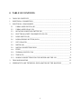
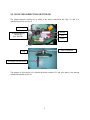
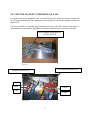
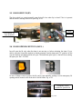
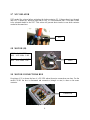
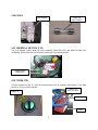
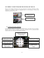
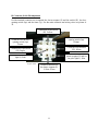
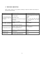
SERVICE MANUAL
CE-9W & CE-15W.
June 2004
0 TABLE OF CONTENTS
0
TABLE OF CONTENTS ____________________________________________________1
1
ELECTRICAL CONNECTION _______________________________________________2
2
ELECTRICAL COMPONENTS ______________________________________________3
2.1
UNBALANCE SWITCH (IR): ____________________________________________4
2.2
UNBALANCE RELAY (R2) _____________________________________________4
2.3
ROTATION DIRECTION SWITCH (IS) ___________________________________5
2.4
ELECTRO-MAGNET COMPONENTS (E & IE): ____________________________6
2.5
DOOR SWITCH (IP) ___________________________________________________7
2.6
DOOR OPENING BUTTON (IAP-L) ______________________________________7
2.7
NTC DELAYER_______________________________________________________8
2.8
MOTOR (M) __________________________________________________________8
2.9
MOTOR CONNECTIONS BOX __________________________________________8
2.10
FUSES _______________________________________________________________9
2.11
THERMAL SWITCH (TM) ______________________________________________9
2.12
TIMER (TP) __________________________________________________________9
2.13
WIRING CONNECTIONS FOR THE MOTOR AND THE LID ________________10
3
TROUBLE SHOOTING ____________________________________________________12
4
SCHEMATICS AND TECHNICAL EXPLANATION OF THE MACHINE __________13
1
1 ELECTRICAL CONNECTIO N
These machines have been designed and manufactured to be connected at 208-230/60/3.
Important: Drum must spin clockwise, such is shown on pictures nº 1 and nº 2. If not, change 2 of
the 3 phases on terminal block. If phases were not connected properly drum will spin
counterclockwise and machine will not brake. However lid opening will be activated and
accident could occur.
Fig. nº1.
Fig. nº2.
2
2 ELECTRICAL COMPONENTS
C1 are the main contactors to spin and brake the machine. Both contactors come installed with
two auxiliary contacts (N113015), one normally closed, one normally open.
4 A. Fuses “F”
Ref : P184011
Relay “R1”
Ref: Z683087
Relay “R2”
Ref: Z683087
Auxiliar
Contact. Ref:
N113015
Terminal block
Spin Contactor
“C1”. Ref:
X183011
Fig. nº3.
Brake Contactor
“C2”
Delayer “NTC”
Ref: N113007
Door switch “Ip”
Door opening
button “Iap” &
cycle light “L”
Door electro- magnet
switch “IE”
&
Door electro- magnet
“E”.
Fig. nº4.
Timer “Tp”
Fig. nº5.
3
2.1 UNBALANCE SWITCH (IR):
If the drum is moving out of control because of the weight of the clothes is not balanced or
because of the shock absorbers are defective, the unbalance switch will stop the spin activating
the R2 relay. Fig. nº 7
In order to continue the spin process, clothes must be balanced, the unbalance switch on position
(Fig. nº 6) and the lid must have been open (Iap).
Activator
Unbalance switch
(IR).
Ref: N103038
Fig. nº6.
2.2 UNBALANCE RELAY (R2)
R2 will be activated when IR is activated in order to stop the machine. R2 has a normally closed
contact connected to C1 (spin contactor). That is why when R2 is activated C1 doesn’t receive
power and machine is stopped. Check schematic.
Unbalance
Relay (R2)
Ref: Z683087
Fig. nº7.
4
2.3 ROTATION DIRECTION SWITCH (IS)
The rotation direction switch (Is) is inside of the motor connections box (Fig. 11) and it is
activated by the clip on fig. 12.
Ending
Brown
Rotation direction
switch (Is).
Ref: N105911
Red.
White.
Fig. nº11.
Pista de rodadura.
Clip
In contact with the motor
Fig. nº12.
The purpose of this switch is to activate the brake contactor C2 and once drum is not moving
activate the opening of the lid.
5
2.4 ELECTRO-MAGNET COMPONENTS (E & IE):
It consists on an electro- magnet (E) and a switch (IE) fig. nº13. When (E) receives voltage the
lid will open automatically. The connection on the solenoid of the electro-magnet is shown on
picture nº 14.
The door switch IE is a normally open contact that will close when lid is closed. If the switch is
open, machine can not operate, preventing so that hydoroextractor will work when lid is open.
Electro- magnet components (E +
IE) Ref: N103028
Fig. nº13 .
Door switch connection (IE).
Solenoid connection (E)
Red.
White.
Yellow.
Blue.
Purple.
Fig. nº14.
6
2.5 DOOR SWITCH (IP)
The door switch is a contact normally open that will close when lip is closed. This is to prevent
that the drum is moving when lid is open. Fig. nº 16.
Purple.
Door switch “Ip”
Ref: N103039
Brown.
Fig. nº15
Fig nº16.
2.6 DOOR OPENING BUTTON (IAP-L)
Iap will open the lid only when the drum is not moving, so before activating the timer. If you
need to open the lid and the machine is already spinning, turn the timer until “O” position. In this
way the machine will brake and lid will open. The button has pilot light (L) that will be on during
the spin cycle. Ref.: Z213033
In case of failure or lack of power, the lid can be open manually pushing over the emergency lid
opening switch located on the front side of the lid holder. Fig. nº 19.
Emergency switch
location to open the lid
Fig. nº19.
7
2.7 NTC DELAYER
NTC works like a timer before activating the brake contactor C2. Voltage doesn’t go through
until NTC is heated up. When the spin time is over, C1 is disconnected but C2 will take a while
to be activated thanks to the NTC. This action will prevent short-circuits in case both contactor
worked at the same time.
NTC
2.8 MOTOR (M)
CE-9W; Ref.: N107701
240V – 415V 60Hz. ½ HP
CE-15W;
Ref :N117701
240V – 415V 60Hz. 1 HP
Motor
2.9 MOTOR CONNECTIONS BOX
On picture nº 21 is shown the box of a CE-15W where the motor connections are done. For the
model CE-9W the box is eliminated and connection (triangle or star) is done on the same
contactor.
Connections
Fig. nº21
8
2.10 FUSES
Fuses 4 A.
Ref: P184011
Fuse holders
2.11 THERMAL SWITCH (TM)
Tm is an internal contact inside the motor normally closed that will open when the motor has
overheated. When motor has cooled down contact will close automatically.
Themal switch
connections
2.12 TIMER (TP)
If timer is placed on the “A” area. the hydorextractor will be working continuously. If not time
from 0 to 15 min. will be selected.
Timer (Tp).
Ref: N113014
Range “A”.
Brown
White
9
2.13 WIRING CONNECTIONS FOR THE MOTOR AND THE LID
There are two terminal connectors for the motor and the lid connections. Working on these
connectors it is possible to check out components and it is not necessary to work on the
component by itself. See fig. nº 28.
Connector for the lid
components
Connector for the
motor components
Fig. nº28.
A) Connector for the motor components
On this terminal connector are connected the thermal switch of the motor (TM), the rotation
direction switch (IS) and the unbalance switch (IR). On picture nº 29 it is shown the male
connector and color of the wire on the electrical schematic.
Connection for the rotation
direction switch ( Is)
Common.White
Connection for the rotation
direction switch ( Is). Red.
Connection for the rotation
direction switch ( Is). Pink.
Connection for the thermal
switch (TM). Black
Connection for the thermal
switch (TM). Yellow.
Connection for the
unbalance switch (IR).
Purple. (Neutral)
Connection for the
unbalance switch (IR).
Orange.
Fig. nº29.
10
B) Connector for the lid components
On this terminal connector are connected the electro- magnet (E) and the switch (IE), the door
opening switch (Iap) and the timer (Tp). See the male connector and wiring colors on picture nº
30
Connection for the switch
(IE). Yellow.
Connection for the door
opening switch (Iap).
Orange.
Connection for the door
opening switch (Iap).
Brown.
Connection for the timer
(TP). White.
Connection for the switch
(IE). Purple.
Neutral connection for the
electro-magnet (E) and for
the pilot light(L). Blue.
Connection for the pilot
light (L).Pink.
Figura nº30.
Ground connection for
the electro- magnet (E).
Yellow-Green
11
3 TROUBLE SHOOTING
NOTE: Before carrying out any operation (checking or repair) the machine must always be
disconnected from the mains
PROBLEM
POSSIBLE CAUSE
No power
WAY TO CORRECT IT
Check out fuses
Close lid or replace close switch if it
Lid is not closed
is broken
The motor does not start.
Timer doesn’t work
Replace
The indicator lamp does
Motor is too hot. Fuse will be
not light up
Terminal fuse of the motor has stopped
activated automatically once motor
the machine
has cool down
Contactor C1 is broken
Replace
Not equilibrated switch has been Deliver the clothes (weight) better
The motor disconnects activated
inside the drum
immediately after starting.
Shock absorvers are defective
Replace
It is probable that two phases were not Check out drum goes clockwise. If
connected properly and spin is not not change phases.
The brake does not work going in the right direcctoin
Contactor C2 or delayer NTC defective Replace
Motor continues working
Timer defective
when time is over
Rotation direction switch defective IS
Lid doesn’t open
Door electro magnet defective E
12
Replace
Replace
Replace
4 SCHEMATICS AND TECHNICAL EXPLANATION OF THE
MACHINE
Review the information below looking at the schematic on next page.
If lid is closed (IP closed) and timer is activated (TP closed) power will go through contact C2
and contact R2 (normally closed), activating C1 contactor. C1 contacts will be closed and motor
M will start spinning clockwise.
Light will come on and Relay R1 will be activated.
If the clothes are not balanced IR will activate Relay R2 and R2 normally closed contact will be
open so C1 will be deactivated and machine will stop.
When time is over C1 is deactivated and power will go through C1 normally closed contact,
through IS but it will not activate C2 immediately because NTC delays it.
When C2 is activated the direction of the spin is counterclockwise, so that will brake the drum
but will not spin, because IS will detect the change of the direction on the rotation and contact
will change position.
When IS contact has changed position, door- magnet E is activated opening the lid (IE).
When drum is not moving and time was not selected, if we press the door opening button Iap E
will be activated and lid will open.
13
14
15